US6170838B1 - Vehicle suspension having active camber variation - Google Patents
Vehicle suspension having active camber variation Download PDFInfo
- Publication number
- US6170838B1 US6170838B1 US09/078,052 US7805298A US6170838B1 US 6170838 B1 US6170838 B1 US 6170838B1 US 7805298 A US7805298 A US 7805298A US 6170838 B1 US6170838 B1 US 6170838B1
- Authority
- US
- United States
- Prior art keywords
- wheel
- chassis
- support
- vehicle
- arm
- Prior art date
- Legal status (The legal status is an assumption and is not a legal conclusion. Google has not performed a legal analysis and makes no representation as to the accuracy of the status listed.)
- Expired - Lifetime
Links
Images


Classifications
-
- B—PERFORMING OPERATIONS; TRANSPORTING
- B62—LAND VEHICLES FOR TRAVELLING OTHERWISE THAN ON RAILS
- B62K—CYCLES; CYCLE FRAMES; CYCLE STEERING DEVICES; RIDER-OPERATED TERMINAL CONTROLS SPECIALLY ADAPTED FOR CYCLES; CYCLE AXLE SUSPENSIONS; CYCLE SIDE-CARS, FORECARS, OR THE LIKE
- B62K5/00—Cycles with handlebars, equipped with three or more main road wheels
- B62K5/10—Cycles with handlebars, equipped with three or more main road wheels with means for inwardly inclining the vehicle body on bends
-
- B—PERFORMING OPERATIONS; TRANSPORTING
- B60—VEHICLES IN GENERAL
- B60G—VEHICLE SUSPENSION ARRANGEMENTS
- B60G21/00—Interconnection systems for two or more resiliently-suspended wheels, e.g. for stabilising a vehicle body with respect to acceleration, deceleration or centrifugal forces
- B60G21/007—Interconnection systems for two or more resiliently-suspended wheels, e.g. for stabilising a vehicle body with respect to acceleration, deceleration or centrifugal forces means for adjusting the wheel inclination
-
- B—PERFORMING OPERATIONS; TRANSPORTING
- B60—VEHICLES IN GENERAL
- B60G—VEHICLE SUSPENSION ARRANGEMENTS
- B60G3/00—Resilient suspensions for a single wheel
- B60G3/01—Resilient suspensions for a single wheel the wheel being mounted for sliding movement, e.g. in or on a vertical guide
-
- B—PERFORMING OPERATIONS; TRANSPORTING
- B60—VEHICLES IN GENERAL
- B60G—VEHICLE SUSPENSION ARRANGEMENTS
- B60G3/00—Resilient suspensions for a single wheel
- B60G3/18—Resilient suspensions for a single wheel with two or more pivoted arms, e.g. parallelogram
- B60G3/20—Resilient suspensions for a single wheel with two or more pivoted arms, e.g. parallelogram all arms being rigid
-
- B—PERFORMING OPERATIONS; TRANSPORTING
- B62—LAND VEHICLES FOR TRAVELLING OTHERWISE THAN ON RAILS
- B62D—MOTOR VEHICLES; TRAILERS
- B62D9/00—Steering deflectable wheels not otherwise provided for
- B62D9/02—Steering deflectable wheels not otherwise provided for combined with means for inwardly inclining vehicle body on bends
-
- B—PERFORMING OPERATIONS; TRANSPORTING
- B62—LAND VEHICLES FOR TRAVELLING OTHERWISE THAN ON RAILS
- B62K—CYCLES; CYCLE FRAMES; CYCLE STEERING DEVICES; RIDER-OPERATED TERMINAL CONTROLS SPECIALLY ADAPTED FOR CYCLES; CYCLE AXLE SUSPENSIONS; CYCLE SIDE-CARS, FORECARS, OR THE LIKE
- B62K5/00—Cycles with handlebars, equipped with three or more main road wheels
- B62K5/02—Tricycles
- B62K5/027—Motorcycles with three wheels
-
- B—PERFORMING OPERATIONS; TRANSPORTING
- B62—LAND VEHICLES FOR TRAVELLING OTHERWISE THAN ON RAILS
- B62K—CYCLES; CYCLE FRAMES; CYCLE STEERING DEVICES; RIDER-OPERATED TERMINAL CONTROLS SPECIALLY ADAPTED FOR CYCLES; CYCLE AXLE SUSPENSIONS; CYCLE SIDE-CARS, FORECARS, OR THE LIKE
- B62K5/00—Cycles with handlebars, equipped with three or more main road wheels
- B62K5/08—Cycles with handlebars, equipped with three or more main road wheels with steering devices acting on two or more wheels
-
- B—PERFORMING OPERATIONS; TRANSPORTING
- B60—VEHICLES IN GENERAL
- B60G—VEHICLE SUSPENSION ARRANGEMENTS
- B60G2200/00—Indexing codes relating to suspension types
- B60G2200/10—Independent suspensions
-
- B—PERFORMING OPERATIONS; TRANSPORTING
- B60—VEHICLES IN GENERAL
- B60G—VEHICLE SUSPENSION ARRANGEMENTS
- B60G2200/00—Indexing codes relating to suspension types
- B60G2200/10—Independent suspensions
- B60G2200/14—Independent suspensions with lateral arms
- B60G2200/144—Independent suspensions with lateral arms with two lateral arms forming a parallelogram
-
- B—PERFORMING OPERATIONS; TRANSPORTING
- B60—VEHICLES IN GENERAL
- B60G—VEHICLE SUSPENSION ARRANGEMENTS
- B60G2200/00—Indexing codes relating to suspension types
- B60G2200/40—Indexing codes relating to the wheels in the suspensions
- B60G2200/422—Driving wheels or live axles
-
- B—PERFORMING OPERATIONS; TRANSPORTING
- B60—VEHICLES IN GENERAL
- B60G—VEHICLE SUSPENSION ARRANGEMENTS
- B60G2200/00—Indexing codes relating to suspension types
- B60G2200/40—Indexing codes relating to the wheels in the suspensions
- B60G2200/44—Indexing codes relating to the wheels in the suspensions steerable
-
- B—PERFORMING OPERATIONS; TRANSPORTING
- B60—VEHICLES IN GENERAL
- B60G—VEHICLE SUSPENSION ARRANGEMENTS
- B60G2200/00—Indexing codes relating to suspension types
- B60G2200/40—Indexing codes relating to the wheels in the suspensions
- B60G2200/46—Indexing codes relating to the wheels in the suspensions camber angle
-
- B—PERFORMING OPERATIONS; TRANSPORTING
- B60—VEHICLES IN GENERAL
- B60G—VEHICLE SUSPENSION ARRANGEMENTS
- B60G2200/00—Indexing codes relating to suspension types
- B60G2200/40—Indexing codes relating to the wheels in the suspensions
- B60G2200/462—Toe-in/out
-
- B—PERFORMING OPERATIONS; TRANSPORTING
- B60—VEHICLES IN GENERAL
- B60G—VEHICLE SUSPENSION ARRANGEMENTS
- B60G2200/00—Indexing codes relating to suspension types
- B60G2200/40—Indexing codes relating to the wheels in the suspensions
- B60G2200/464—Caster angle
-
- B—PERFORMING OPERATIONS; TRANSPORTING
- B60—VEHICLES IN GENERAL
- B60G—VEHICLE SUSPENSION ARRANGEMENTS
- B60G2202/00—Indexing codes relating to the type of spring, damper or actuator
- B60G2202/40—Type of actuator
-
- B—PERFORMING OPERATIONS; TRANSPORTING
- B60—VEHICLES IN GENERAL
- B60G—VEHICLE SUSPENSION ARRANGEMENTS
- B60G2202/00—Indexing codes relating to the type of spring, damper or actuator
- B60G2202/40—Type of actuator
- B60G2202/41—Fluid actuator
- B60G2202/413—Hydraulic actuator
-
- B—PERFORMING OPERATIONS; TRANSPORTING
- B60—VEHICLES IN GENERAL
- B60G—VEHICLE SUSPENSION ARRANGEMENTS
- B60G2204/00—Indexing codes related to suspensions per se or to auxiliary parts
- B60G2204/10—Mounting of suspension elements
- B60G2204/14—Mounting of suspension arms
- B60G2204/143—Mounting of suspension arms on the vehicle body or chassis
-
- B—PERFORMING OPERATIONS; TRANSPORTING
- B60—VEHICLES IN GENERAL
- B60G—VEHICLE SUSPENSION ARRANGEMENTS
- B60G2204/00—Indexing codes related to suspensions per se or to auxiliary parts
- B60G2204/10—Mounting of suspension elements
- B60G2204/14—Mounting of suspension arms
- B60G2204/148—Mounting of suspension arms on the unsprung part of the vehicle, e.g. wheel knuckle or rigid axle
-
- B—PERFORMING OPERATIONS; TRANSPORTING
- B60—VEHICLES IN GENERAL
- B60G—VEHICLE SUSPENSION ARRANGEMENTS
- B60G2204/00—Indexing codes related to suspensions per se or to auxiliary parts
- B60G2204/10—Mounting of suspension elements
- B60G2204/30—In-wheel mountings
-
- B—PERFORMING OPERATIONS; TRANSPORTING
- B60—VEHICLES IN GENERAL
- B60G—VEHICLE SUSPENSION ARRANGEMENTS
- B60G2204/00—Indexing codes related to suspensions per se or to auxiliary parts
- B60G2204/40—Auxiliary suspension parts; Adjustment of suspensions
- B60G2204/421—Pivoted lever mechanisms for mounting suspension elements, e.g. Watt linkage
-
- B—PERFORMING OPERATIONS; TRANSPORTING
- B60—VEHICLES IN GENERAL
- B60G—VEHICLE SUSPENSION ARRANGEMENTS
- B60G2204/00—Indexing codes related to suspensions per se or to auxiliary parts
- B60G2204/40—Auxiliary suspension parts; Adjustment of suspensions
- B60G2204/422—Links for mounting suspension elements
-
- B—PERFORMING OPERATIONS; TRANSPORTING
- B60—VEHICLES IN GENERAL
- B60G—VEHICLE SUSPENSION ARRANGEMENTS
- B60G2204/00—Indexing codes related to suspensions per se or to auxiliary parts
- B60G2204/40—Auxiliary suspension parts; Adjustment of suspensions
- B60G2204/423—Rails, tubes, or the like, for guiding the movement of suspension elements
- B60G2204/4232—Sliding mounts
-
- B—PERFORMING OPERATIONS; TRANSPORTING
- B60—VEHICLES IN GENERAL
- B60G—VEHICLE SUSPENSION ARRANGEMENTS
- B60G2204/00—Indexing codes related to suspensions per se or to auxiliary parts
- B60G2204/62—Adjustable continuously, e.g. during driving
-
- B—PERFORMING OPERATIONS; TRANSPORTING
- B60—VEHICLES IN GENERAL
- B60G—VEHICLE SUSPENSION ARRANGEMENTS
- B60G2204/00—Indexing codes related to suspensions per se or to auxiliary parts
- B60G2204/80—Interactive suspensions; arrangement affecting more than one suspension unit
- B60G2204/82—Interactive suspensions; arrangement affecting more than one suspension unit left and right unit on same axle
-
- B—PERFORMING OPERATIONS; TRANSPORTING
- B60—VEHICLES IN GENERAL
- B60G—VEHICLE SUSPENSION ARRANGEMENTS
- B60G2204/00—Indexing codes related to suspensions per se or to auxiliary parts
- B60G2204/80—Interactive suspensions; arrangement affecting more than one suspension unit
- B60G2204/83—Type of interconnection
- B60G2204/8302—Mechanical
-
- B—PERFORMING OPERATIONS; TRANSPORTING
- B60—VEHICLES IN GENERAL
- B60G—VEHICLE SUSPENSION ARRANGEMENTS
- B60G2206/00—Indexing codes related to the manufacturing of suspensions: constructional features, the materials used, procedures or tools
- B60G2206/01—Constructional features of suspension elements, e.g. arms, dampers, springs
- B60G2206/50—Constructional features of wheel supports or knuckles, e.g. steering knuckles, spindle attachments
-
- B—PERFORMING OPERATIONS; TRANSPORTING
- B60—VEHICLES IN GENERAL
- B60G—VEHICLE SUSPENSION ARRANGEMENTS
- B60G2206/00—Indexing codes related to the manufacturing of suspensions: constructional features, the materials used, procedures or tools
- B60G2206/01—Constructional features of suspension elements, e.g. arms, dampers, springs
- B60G2206/60—Subframe construction
- B60G2206/605—Flexible constructions
-
- B—PERFORMING OPERATIONS; TRANSPORTING
- B60—VEHICLES IN GENERAL
- B60G—VEHICLE SUSPENSION ARRANGEMENTS
- B60G2300/00—Indexing codes relating to the type of vehicle
- B60G2300/27—Racing vehicles, e.g. F1
-
- B—PERFORMING OPERATIONS; TRANSPORTING
- B60—VEHICLES IN GENERAL
- B60G—VEHICLE SUSPENSION ARRANGEMENTS
- B60G2500/00—Indexing codes relating to the regulated action or device
- B60G2500/30—Height or ground clearance
-
- B—PERFORMING OPERATIONS; TRANSPORTING
- B60—VEHICLES IN GENERAL
- B60G—VEHICLE SUSPENSION ARRANGEMENTS
- B60G2600/00—Indexing codes relating to particular elements, systems or processes used on suspension systems or suspension control systems
- B60G2600/18—Automatic control means
- B60G2600/182—Active control means
-
- B—PERFORMING OPERATIONS; TRANSPORTING
- B60—VEHICLES IN GENERAL
- B60G—VEHICLE SUSPENSION ARRANGEMENTS
- B60G2800/00—Indexing codes relating to the type of movement or to the condition of the vehicle and to the end result to be achieved by the control action
- B60G2800/01—Attitude or posture control
- B60G2800/012—Rolling condition
-
- B—PERFORMING OPERATIONS; TRANSPORTING
- B60—VEHICLES IN GENERAL
- B60G—VEHICLE SUSPENSION ARRANGEMENTS
- B60G2800/00—Indexing codes relating to the type of movement or to the condition of the vehicle and to the end result to be achieved by the control action
- B60G2800/21—Traction, slip, skid or slide control
- B60G2800/212—Transversal; Side-slip during cornering
-
- B—PERFORMING OPERATIONS; TRANSPORTING
- B60—VEHICLES IN GENERAL
- B60G—VEHICLE SUSPENSION ARRANGEMENTS
- B60G2800/00—Indexing codes relating to the type of movement or to the condition of the vehicle and to the end result to be achieved by the control action
- B60G2800/21—Traction, slip, skid or slide control
- B60G2800/214—Traction, slip, skid or slide control by varying the load distribution
-
- B—PERFORMING OPERATIONS; TRANSPORTING
- B60—VEHICLES IN GENERAL
- B60G—VEHICLE SUSPENSION ARRANGEMENTS
- B60G2800/00—Indexing codes relating to the type of movement or to the condition of the vehicle and to the end result to be achieved by the control action
- B60G2800/24—Steering, cornering
Definitions
- the present invention relates to a suspension for vehicles, in particular road vehicles. It relates both to the guidance of a vehicle wheel relative to the body of this vehicle and to the organization of the deflection of the wheel relative to the chassis. It relates more particularly to means used for actively controlling the position of the wheel plane relative to the body.
- a wheel is mounted on a hub and that the hub is mounted on a wheel carrier by means of a rolling bearing which embodies the axis of rotation of the wheel.
- the guidance of the wheel involves allowing the wheel carrier to be displaced relative to the vehicle by an extent which is sufficient for the suspension of the vehicle.
- the guidance of the wheel must be such that the control of the path of the vehicle via the grip of the tires on the ground is ensured under the best possible conditions.
- the deflecting movement which is sought is of great extent in the vertical direction.
- the control of the deflecting movements is tantamount to saying that guidance must ensure a strictly controlled position of the plane of the wheel relative to the chassis. It is still possible to define a longitudinal and vertical plane forming a reference to identify the preferred running direction which is parallel to said longitudinal plane. The purpose of guiding the plane of the wheel is to control as strictly as possible the relative position of the plane of the wheel relative to said longitudinal plane in terms of angle and distance.
- pendulum suspensions increase the overload on the wheels located on the outside of the bend by displacing the center of gravity of the vehicle toward the outside of the bend. This is particularly detrimental with regard to road vehicles equipped with tires.
- active or semiactive suspensions the control of which is now made possible by advances in electronics.
- active or semiactive suspensions are transplanted onto suspensions which are still of traditional mechanical design, said control means being adapted to the defects of these suspensions, without looking to make use of new parameters in suspension kinematics.
- active or semiactive suspensions are concerned simply with controlling the damping characteristics of the suspensions and even the flexibility characteristics, while at the same time preserving suspension kinematics derived directly from conventional forms of construction.
- the object of the invention is to improve the operating safety of vehicles by means of suspension kinematics allowing active control of the camber of the wheel, in order to maintain the tires in a position relative to the ground which is as favorable as possible to their grip and their fatigue strength, even in the event of extremely severe stresses.
- the invention provides a vehicle comprising:
- a suspended running chassis making it possible to define thereon a longitudinal and vertical plane forming a reference, the preferred running direction of the vehicle being parallel to said longitudinal plane,
- each of the wheel connecting systems comprising a wheel, said wheel connecting systems being mounted on said chassis on either side of the latter in a transverse direction, each of the wheel connecting systems comprising a wheel mounted on a support by means of a suspension device allowing deflection of the wheel relative to the support, said suspensions being independent of one another, the deflecting movement taking place in the plane of the wheel, the deflection stroke being sufficient to afford the required vertical suspension movement,
- each support is mounted on said chassis by means of a camber mechanism making it possible to vary the camber angle of the corresponding wheel, said camber mechanism acting between the chassis and each support, so as to incline the plane of each wheel relative to said longitudinal plane in order to impart a camber angle of desired amplitude to the planes of said wheels, thus inclining all the wheels relative to the ground in the same direction.
- the vehicle comprises at least one sensor for recording the value of at least one parameter making it possible to evaluate the transverse acceleration exerted on the vehicle, and calculation means for calculating the amplitude of each camber angle as a function of the value or values recorded, said camber mechanism comprising control means acting under the control of said calculation means.
- the transverse acceleration in question is the centrifugal force occurring on a bend.
- the invention allows active control of the camber of the wheels.
- a tendency of tires to exhibit pronounced wear at the shoulders is combatted effectively, this tendency being well known in passenger cars driven for sport.
- the tread may be excessively offset axially toward the center of the vehicle.
- the active control of the camber corrects this tendency.
- the mode of functioning of the tire remains as far as possible optimal.
- camber is the angle which the plane of the wheel forms relative to a straight line perpendicular to the ground.
- it is not possible to act directly thereon by controlling the position of the wheel relative to the ground, since it is inconceivable to come to bear on the ground itself in order to control the camber variation. It is possible only to act indirectly via a mechanism connected to the chassis.
- the invention applies particularly to four-wheeled vehicles, such as passenger cars.
- the camber angle variation concerned here is of great extent, that is to say is nearer the values frequently swept by motorcycles than the set values which may exist in a conventional four-wheeled passenger car.
- the range of variation is of the order of ⁇ 15° to ⁇ 2°. At all events, the range of variation is such that, when the wheel tilts about its area of contact with the ground, the transverse displacement of the radially upper part of the wheel may reach an extent greater than the width of said wheel.
- the amplitude of the camber is possibly not identical for each of the wheels of the vehicle, whereas the tilting direction of the wheels is always the same and is directed opposite to the transverse acceleration originating from the centrifugal force. The top of the wheel therefore tilts in the centripetal direction.
- the invention provides suspension kinematics which are as pure as possible: the wheel connecting system not only offers vertical suspension, but it also makes it possible to modify the camber of the wheel at any moment, without thereby reducing the stroke of the vertical suspension in terms of either compression or expansion, while at the same time maintaining vertical suspension under optimal operating conditions. Strictly speaking, it would be more appropriate to refer to deflection located in the wheelplane and directed perpendicularly to the running movement of the vehicle. For the sake of linguistic convenience, this degree of freedom is designated by “vertical suspension”.
- the invention provides an assembly making it possible to integrate the guidance and the elements necessary for the so-called vertical suspension into the interior of the wheel.
- the essential functions of the suspension are thereby integrated into the volume within the wheel. This makes it possible to ensure that the assembly is highly compact.
- the invention provides a passenger car with active control of roll: the passenger compartment of the vehicle is mounted on the chassis in such a way that said compartment can be inclined toward the inside of the bend as a function of the centrifugal force.
- roll is a measure of the lean angle of the passenger compartment relative to the ground
- action is taken on the roll angle indirectly by bearing on the chassis.
- the object is to achieve a substantial range of variation of the roll angle of the passenger compartment, of the same order of magnitude as the range of variation of the camber.
- the effect produced is sufficiently noticeable to alter radically the impression felt by the passengers of such a vehicle and thus to contribute to their comfort.
- Another embodiment provides a horizontal suspension of the wheels, that is to say a suspension which allows the wheels to move along the longitudinal axis relative to the chassis when they encounter an obstacle. This contributes to comfort by avoiding transmitting violent shocks to the tire, due to the reduction in the impact speed.
- the invention will be understood better from the following description relating to a four wheeled vehicle.
- the invention applies particularly to vehicles comprising at least four wheels, although the example given is not limiting.
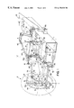
- FIG. 1 is a partial perspective view showing one quarter of a vehicle
- FIG. 2 is a diagrammatic front view showing the main members of a wheel connecting system, with two camber values being superposed one on the other;
- FIG. 3 is a diagrammatic top view showing the main members of a wheel connecting system, with two positions for the horizontal deflection of the suspension being superposed one on the other;
- FIG. 4 is a flow chart illustrating the control of the wheel connections.
- FIG. 1 shows, in particular, a chassis 1 which consists of a central beam and to which all the members of the vehicle are fastened.
- Each wheel connecting system of the vehicle is preferably identical.
- Four wheels 2 are therefore mounted on the chassis 1 by means of identical members, and because of this it is sufficient to describe only one of the wheel connecting systems in order to describe the invention fully.
- a support 5 belonging to a wheel connecting system, and its mounting points on the vehicle: two lower points 50 , forming a horizontal axis AA′, and an upper point 52 at the end of a bracket 51 .
- a lever 61 on the end of which action is taken in order to control the steering of the wheel 2 .
- the levers 61 are controlled by a steering mechanism, a control rod 62 of which can be seen.
- the steering mechanism is to make the angle of steering of the wheels sufficiently insensitive to variations in camber (and also to variations in roll if the roll of the body is controlled actively—a suitable installation is given below).
- a simplified wheel connecting system is used, which prevents steering of the wheel, or the wheel carrier 56 is immobilized by connecting a link to the levers 61 in a suitable way, in this case preferably a link of adjustable length.
- the wheel carrier 56 is mounted on the support 5 by means of a single bar 55 sliding in the support 5 , the wheel carrier being mounted without any degree of freedom on the bar 55 at the two ends of the latter, said bar 55 being arranged in the volume delimited radially by the rim of said wheel 2 , said suspension device comprising means for controlling the deflection of the wheel carrier relative to the support. This is how it is possible for the wheel 2 to be deflected vertically relative to the support 5 .
- a traction motor 8 for example a hydraulic or electric motor, can be seen, this type of traction being more convenient to install than a transmission by means of a mechanical shaft, in light of the need to accommodate the camber variations.
- a spring and shock absorber which are not illustrated in FIG. 1 so as not to overload the drawing. It will be possible, for example, to arrange a spring parallel to the bar 55 and offset relative to the latter, said spring being accommodated within the rim and in front of the slideway in FIG. 1.
- a linear or rotary shock absorber which may be accommodated on the other side of the slideway, could be used. One of these or both may, of course, be under active control, the invention not dealing per se with the spring and damping functions.
- the support 5 is fastened to the chassis 1 of the vehicle by means of an arm 70 and a rod 75 .
- the end of the arm 70 forms a fork 71 connected to the support 5 by means of the first two points 50 , with possibility of tilting of the support 5 relative to the arm 70 about the axis AA′.
- the arm 70 is mounted on the chassis of the vehicle so as to be capable of transmitting the suspended weight of the latter and transferring it to the support 5 .
- the arm could be purely and simply mounted in the chassis 1 , if independent horizontal suspension is not to be provided. There is still a degree of freedom of tilting of the support 5 about the axis AA′.
- the rod 75 is displaced transversely relative to the arm 70 in order to vary the position of the point 52 relative to the position of the axis AA′, thus making it possible to change the camber value of the wheel 2 .
- the camber mechanism of the vehicle comprises an arm 70 mounted on the support 5 on an axis of support oriented substantially parallel to said longitudinal plane, and mounted on the chassis 1 without any possibility of tilting about a longitudinal axis relative to said chassis, so as to transmit the weight carried by the chassis 1 to the support 5 by means of said arm, the camber mechanism comprising a means for tilting the support about said axis of support 5 .
- the design arrangement provided by the invention makes it possible, for any camber and steering value and for any value of the deflection of the horizontal suspension, to maintain, in the plane of the wheel, the degree of freedom of deflection which vertical suspension requires. It is also because of this that the tire always remains under optimal operating conditions, even when the functioning of the tire in a transient state is considered. On a bend, and therefore when there is even appreciable camber, the vertical deflection of the wheel which may possibly be caused by uneven ground does not significantly change the way the vehicle bears transversely on its wheels. As is obvious, at this moment, a vehicle bears essentially on the wheels located on the outside of the bend. Any tendency to cause transverse variations in the groundbearing reactions of the path of the vehicle is effectively combatted.
- each of the wheel connecting systems comprises a hub designed for supporting a wheel 2 and comprises a wheel carrier defining the axis of rotation of the hub, said wheel carrier being guided translationally relative to the support in a rectilinear movement parallel to a perpendicular to the axis of rotation of the hub, the support 5 comprising at least one mounting point to enable the support 5 to be mounted on said chassis 1 .
- the vehicle illustrating the invention comprises a horizontal suspension
- the arm 70 and the rod 75 are not directly mounted on the chassis. It is necessary for the camber mechanism to be capable of following the movements of the horizontal suspension, without inducing any unwanted variation in the camber. Before the details of the camber mechanism are described, let us first examine the design of the horizontal suspension.
- the arm 70 which transfers the weight of the vehicle to the wheel 2 , is connected to the chassis 1 , while at the same time a movement of the arm allowing horizontal suspension is permitted.
- the arm 70 is part of a component forming an angle piece 7 .
- the latter comprises a vertical branch 72 .
- yokes allowing connection to a box 3 via a vertical axis of articulation CC′.
- the horizontal branch of the angle piece 7 that is to say the arm 70 , comprises a ball joint 73 forming a vertical axis which is arranged transversely on that side 74 of the arm 70 opposite the fork 71 and which is arranged longitudinally on the opposite side to the vertical branch 72 .
- FIG. 3 makes it possible to understand how the horizontal suspension functions. It can be seen, in particular, that the position of the arm 70 and of the box 3 is represented by unbroken lines for a mid-position and by broken lines for another position. The stroke of such a horizontal suspension is a matter of centimeters, without the horizontal deflection interfering either with the camber or with the steering. Consequently, a rocker 79 , correctly articulated on the arm 70 , allows the steering control rod 62 to follow the deflecting movements of the horizontal suspension, without causing any induced steering.
- the vehicle weight is transmitted to the wheel 2 via the box 3 .
- the box 3 is mounted on the chassis 1 on a vertical axis DD′ obtained by means of two separate yokes 31 and 32 .
- a link 30 forms a parallelogram with the box 3 , the assembly as a whole being seen in a horizontal plane (see FIG. 3 ).
- the link 30 is mounted on the chassis 1 by means of a pivot 33 .
- the horizontal movement of the arm 70 is controlled by a suitable device 35 , for example a simple rubber block, in light of the small deflections for which allowance need be allowed.
- the arm 70 is mounted on the chassis 1 on at least two vertical axes (here, the axes CC′ and DD′) which are parallel and horizontally separated, these constituting vertices of a horizontal suspension mechanism forming a parallelogram, as seen in a horizontal plane, the other two vertices being integral with the chassis 1 .
- each wheel 2 forms a parallelogram, two vertices of which are formed by two mounting points 50 , 52 located on the support 5 and arranged vertically one above the other and two sides of which are formed by the arm 70 and the rod 75 parallel thereto, the arm and the rod terminating at the mounting points 50 , 52 .
- This parallelogram makes it possible for the mounting points 50 , 52 of the support 5 to be offset transversely toward the chassis.
- the length of the rod 75 corresponds to the length of the arm 70 , as measured between the axes AA′ and BB′.
- the rod 75 connects the point 52 of the support 5 to the point 750 located on a pivoted lever 40 oscillating about the axis BB′.
- a camber lever 4 is mounted on the chassis 1 so as to oscillate about a longitudinal axis XX′ and is mounted at a chassis point 43 located transversely at the center of the vehicle.
- a rod 44 connects a ball joint 41 of the lever 40 to a ball joint 42 of the camber lever 4 , the point 46 (located on the axis BB′) the ball joints 41 , 42 and the point 43 forming a parallelogram.
- the ball joints 41 and 42 adapt both to the camber variations imparted to the wheel 2 and the horizontal displacements attributable to the degree of freedom introduced by the horizontal suspension.
- a jack 45 is interposed between the camber lever 4 and the chassis 1 .
- the jack 45 is controlled in such a way that it assumes a specific length according to the camber angle which is to be imparted to the wheels 2 .
- a look at FIG. 2 makes it possible to understand the organization of the movements for controlling the wheel camber. There can be seen, in particular, the position of the rod 75 and the configuration of the lever 40 and of the camber lever 4 , as represented by unbroken lines with regard to zero camber and by broken lines as regards a nonzero value of the camber.
- the passenger compartment of the vehicle either it is integral with the chassis 1 or it is pivotally mounted on the chassis 1 on a longitudinal axis of articulation XX′ passing through the point 43 .
- the vehicle is such that it comprises:
- a passenger compartment for the transport of passengers which is mounted on the chassis 1 so as to be inclinable about a longitudinal axis, in such a way that the passenger compartment forms a variable roll angle relative to said chassis 1 ,
- calculation means for calculating said roll angle as a function of the value or values recorded, said interposed mechanical means acting under the control of said calculation means.
- the passenger compartment assumes a roll angle relative to the chassis 1 which is identical to the camber angle imparted to the wheels.
- the camber mechanisms of each of the wheels are actuated by said mechanical means interposed between the chassis 1 and the passenger compartment, in such a way that the variation in camber of the wheels and the variation in the roll angle of the passenger compartment are synchronous.
- This contributes to the comfort of the passengers, additionally due to a perception of greater safety in the movement of the vehicle. It may be noted that this also contributes per se to safety, in that the center of gravity of the vehicle is displaced toward the inside of the bend, thus reducing the load fraction which is transferred to the wheels located on the outside of the bend.
- the tires work in a more favorable position relative to the ground, but, furthermore, in this embodiment, the instantaneous overload on the tires on the outside of the bend is lower than if there were no correction of camber.
- At least one sensor S may be installed on the vehicle in order to record the value of at least one parameter making it possible to evaluate said centrifugal force.
- This may be a direct measurement of the centrifugal acceleration or else an evaluation as a function of indirect parameters, such as the speed of the vehicle and the steering wheel angle, as shown in FIG. 4 .
- calculation means for example, a microprocessor M loaded with the appropriate program
- Such a strategy may take into account various choices for implementing it, such as, for example, a proportionality value setting the level of transverse acceleration at which the maximum roll angle permitted by the roll mechanism is reached. On the basis of the roll angle calculated, it is possible to control the jack 45 , as shown in FIG. 4 .
Landscapes
- Engineering & Computer Science (AREA)
- Mechanical Engineering (AREA)
- Chemical & Material Sciences (AREA)
- Combustion & Propulsion (AREA)
- Transportation (AREA)
- Vehicle Body Suspensions (AREA)
Priority Applications (2)
| Application Number | Priority Date | Filing Date | Title |
|---|---|---|---|
| US09/710,296 US6406036B1 (en) | 1997-05-16 | 2000-11-11 | Vehicle suspension having active camber variation |
| US10/097,070 US6547260B2 (en) | 1997-05-16 | 2002-03-13 | Vehicle suspension having active camber variation |
Applications Claiming Priority (2)
| Application Number | Priority Date | Filing Date | Title |
|---|---|---|---|
| FR9706227A FR2763300A1 (fr) | 1997-05-16 | 1997-05-16 | Vehicule comportant une suspension a variation de carrossage actif |
| FR9706227 | 1997-05-16 |
Related Child Applications (1)
| Application Number | Title | Priority Date | Filing Date |
|---|---|---|---|
| US09/710,296 Division US6406036B1 (en) | 1997-05-16 | 2000-11-11 | Vehicle suspension having active camber variation |
Publications (1)
| Publication Number | Publication Date |
|---|---|
| US6170838B1 true US6170838B1 (en) | 2001-01-09 |
Family
ID=9507099
Family Applications (1)
| Application Number | Title | Priority Date | Filing Date |
|---|---|---|---|
| US09/078,052 Expired - Lifetime US6170838B1 (en) | 1997-05-16 | 1998-05-13 | Vehicle suspension having active camber variation |
Country Status (6)
| Country | Link |
|---|---|
| US (1) | US6170838B1 (pt) |
| EP (2) | EP0878378B1 (pt) |
| JP (1) | JP4013094B2 (pt) |
| BR (1) | BR9801627A (pt) |
| DE (2) | DE69818524T2 (pt) |
| FR (1) | FR2763300A1 (pt) |
Cited By (84)
| Publication number | Priority date | Publication date | Assignee | Title |
|---|---|---|---|---|
| US6467783B1 (en) * | 1999-07-23 | 2002-10-22 | Compagnie Generale Des Et Establissements Michelin-Michelin & Cie | Motor vehicle equipped with a system for controlling the camber of the wheels of the vehicle on a bend |
| US6511078B2 (en) | 2000-04-10 | 2003-01-28 | Conception Et Developpement Michelin S.A. | Vehicle having suspension system with variable camber and vertical suspension in the plane of the wheel |
| US6671598B2 (en) | 2001-11-23 | 2003-12-30 | Conception Et Developpement Michelin S.A. | Electrical steering for vehicle |
| EP1380459A1 (en) * | 2001-04-16 | 2004-01-14 | Kabushiki Kaisha Bridgestone | Fixing method of in-wheel motor and in-wheel motor system |
| US6688620B2 (en) | 2000-03-27 | 2004-02-10 | Michelin Recherche Et Technique S.A. | Vehicle suspension with camber control |
| US20050017471A1 (en) * | 2003-06-09 | 2005-01-27 | Matthew Kim | Steering with triple linkage suspension having steering adjusted camber |
| US20050051976A1 (en) * | 2001-01-23 | 2005-03-10 | Michelin Recherche Et Technique S.A. | Suspension device of a motor vehicle wheel |
| US20050087941A1 (en) * | 2003-10-24 | 2005-04-28 | Nissan Motor Co., Ltd. | Independent suspension system for a wheeled vehicle |
| US20050236797A1 (en) * | 2002-12-27 | 2005-10-27 | Michelin Recherch Et Technique S.A. | Wheel support device with three pivots, suspension device and vehicle comprising said support device |
| US20050275181A1 (en) * | 2002-09-18 | 2005-12-15 | Macisaac William L | Vehicle with movable and inwardly tilting safety body |
| US20060017240A1 (en) * | 2004-07-15 | 2006-01-26 | Conception Et Developpement Michelin S.A. | Vehicle with a suspension system that allows individual suspension of the wheels and active control of the body height |
| US20060220335A1 (en) * | 2003-02-07 | 2006-10-05 | Jurgen Damm | Method and device for wheel camber adjustment |
| US20060264151A1 (en) * | 2005-04-07 | 2006-11-23 | Traxxas | Vehicle suspension for a model vehicle |
| US7185902B1 (en) | 2003-03-14 | 2007-03-06 | Altair Engineering, Inc. | Strut suspension with pivoting rocker arm |
| US20070120332A1 (en) * | 2005-11-29 | 2007-05-31 | Bushko Dariusz A | Active Vehicle Suspension System |
| US20070120333A1 (en) * | 2005-11-29 | 2007-05-31 | Bushko Dariusz A | Active vehicle suspension system |
| US20070176386A1 (en) * | 2006-02-01 | 2007-08-02 | Schlangen Adam J | Independent rear suspension system for an all terrain vehicle |
| US20070205576A1 (en) * | 2006-03-06 | 2007-09-06 | Purdue Research Foundation | Swinging hub for adjusting wheel camber |
| US20070246903A1 (en) * | 2006-04-20 | 2007-10-25 | Melcher Thomas W | Motor Vehicle with Leaning System Controlled by Load Sensor and Method Therefor |
| US20080042329A1 (en) * | 2004-07-02 | 2008-02-21 | Michel Deal | Motor Vehicle Suspension Device |
| US7357400B2 (en) * | 2003-08-18 | 2008-04-15 | Michelin Recherche Et Technique S.A. | Suspension device for vehicle wheels |
| US20080100021A1 (en) * | 2005-08-18 | 2008-05-01 | Toyota Jidosha Kabushiki Kaisha | In-Wheel Suspension |
| US20080223637A1 (en) * | 2006-12-19 | 2008-09-18 | Bradley Wayne Bartilson | Safe, Super-efficient, Four-wheeled Vehicle Employing Large Diameter Wheels with Continuous-Radius Tires, with Leaning Option |
| US20090036021A1 (en) * | 2005-04-07 | 2009-02-05 | Brent Whitfield Byers | Rocker arm assembly for a model vehicle |
| US20090194965A1 (en) * | 2008-01-31 | 2009-08-06 | Roy Boston | Vehicle Suspension System with a Variable Camber System |
| US20090256326A1 (en) * | 2008-04-10 | 2009-10-15 | Sacli Suspension, Llc | Suspension system providing two degrees of freedom |
| US20090261550A1 (en) * | 2006-04-10 | 2009-10-22 | Gm Global Technology Operations, Inc. | Steering knuckle for a vehicle |
| US20100090431A1 (en) * | 2006-12-21 | 2010-04-15 | Zf Friedrichshafen Ag | Wheel suspension |
| US7699326B2 (en) * | 2005-08-30 | 2010-04-20 | Toyota Jidosha Kabushiki Kaisha | In-wheel suspension |
| US20100117313A1 (en) * | 2008-11-11 | 2010-05-13 | Hyundai Motor Company | Active Geometry Control Suspension |
| US20100320023A1 (en) * | 2009-06-23 | 2010-12-23 | Michael Rhodig | Four wheel vehicle having a rotatable body section and method therefor |
| US20110148060A1 (en) * | 2006-10-23 | 2011-06-23 | James Franklin Cuttino | Passive vehicle suspension system providing optimal camber gain |
| US8360440B2 (en) * | 2009-07-10 | 2013-01-29 | Bombardier Recreational Products Inc. | Control system for leaning vehicle |
| US20150123367A1 (en) * | 2012-06-04 | 2015-05-07 | John Victor Gano | Multi-Axis Caster Angle Control System of an Extendable Wheel Assembly |
| US20150151598A1 (en) * | 2012-06-14 | 2015-06-04 | Daimler Ag | Wheel Suspension |
| US20150165855A1 (en) * | 2013-12-18 | 2015-06-18 | Automotive Research & Testing Center | Active vehicle with a variable inclination apparatus and method of using the same |
| US20150183286A1 (en) * | 2012-06-14 | 2015-07-02 | Daimler Ag | Wheel Suspension |
| US9545976B2 (en) | 2013-02-28 | 2017-01-17 | Thomas W. Melcher | Snowmobile with leaning capability |
| US9969228B2 (en) * | 2016-09-29 | 2018-05-15 | David R. Hall | Vehicle inboard suspension system |
| USD828460S1 (en) | 2017-01-27 | 2018-09-11 | Traxxas, LP | Shock tower for a model vehicle |
| US10137965B2 (en) | 2013-02-28 | 2018-11-27 | Thomas W. Melcher | Snowmobile with leaning capability and improvements therefor |
| USD839363S1 (en) | 2015-09-18 | 2019-01-29 | Traxxas Llp | Shock tower for a model vehicle |
| US20190111746A1 (en) * | 2017-10-13 | 2019-04-18 | Honda Motor Co., Ltd. | Suspension device |
| US10414233B2 (en) * | 2015-01-22 | 2019-09-17 | Shanghai Lunliang Mechanical And Electrical Science-Technology Co., Ltd. | Multi-bearing-point independent suspension |
| USD875186S1 (en) | 2018-01-10 | 2020-02-11 | Traxxas Lp | Upper front suspension arm for a model vehicle |
| US10598292B2 (en) | 2016-05-06 | 2020-03-24 | Thomas W. Melcher | Hydraulic bypass system |
| USD896709S1 (en) | 2019-06-28 | 2020-09-22 | Traxxas Lp | Model vehicle shock tower |
| US10814690B1 (en) | 2017-04-18 | 2020-10-27 | Apple Inc. | Active suspension system with energy storage device |
| USD902090S1 (en) | 2019-09-10 | 2020-11-17 | Traxxas Lp | Model vehicle lower suspension arm |
| USD902089S1 (en) | 2019-09-10 | 2020-11-17 | Traxxas Llp | Model vehicle upper suspension arm |
| USD905798S1 (en) | 2019-06-27 | 2020-12-22 | Traxxas Lp | Model vehicle upper suspension arm |
| USD905799S1 (en) | 2019-06-27 | 2020-12-22 | Traxxas Lp | Model vehicle lower suspension arm |
| US10899340B1 (en) | 2017-06-21 | 2021-01-26 | Apple Inc. | Vehicle with automated subsystems |
| US10906370B1 (en) | 2017-09-15 | 2021-02-02 | Apple Inc. | Active suspension system |
| US10960723B1 (en) | 2017-09-26 | 2021-03-30 | Apple Inc. | Wheel-mounted suspension actuators |
| US11046143B1 (en) | 2015-03-18 | 2021-06-29 | Apple Inc. | Fully-actuated suspension system |
| CN113272218A (zh) * | 2018-12-10 | 2021-08-17 | 比亚乔股份有限公司 | 用于带有两个前转向轮的车辆的前轮架和包含前轮架的机动车辆 |
| USD929507S1 (en) | 2019-06-27 | 2021-08-31 | Traxxas Lp | Model vehicle shock tower |
| USD930088S1 (en) | 2019-06-27 | 2021-09-07 | Traxxas Lp | Model vehicle shock tower |
| US11124035B1 (en) | 2017-09-25 | 2021-09-21 | Apple Inc. | Multi-stage active suspension actuator |
| US11173766B1 (en) | 2017-09-07 | 2021-11-16 | Apple Inc. | Suspension system with locking structure |
| US11179991B1 (en) | 2019-09-23 | 2021-11-23 | Apple Inc. | Suspension systems |
| USD944901S1 (en) | 2019-12-06 | 2022-03-01 | Traxxas Lp | Model vehicle lower suspension arm |
| US11285773B1 (en) | 2018-09-12 | 2022-03-29 | Apple Inc. | Control system |
| USD947957S1 (en) | 2019-12-11 | 2022-04-05 | Traxxas Lp | Model vehicle upper suspension arm |
| USD951151S1 (en) | 2019-10-31 | 2022-05-10 | Traxxas, L.P. | Model vehicle lower suspension arm |
| USD951148S1 (en) | 2019-10-31 | 2022-05-10 | Traxxas, L.P. | Model vehicle lower suspension arm |
| USD951149S1 (en) | 2019-10-31 | 2022-05-10 | Traxxas, L.P. | Model vehicle upper suspension arm |
| USD951150S1 (en) | 2019-10-31 | 2022-05-10 | Traxxas, L.P. | Model vehicle lower suspension arm |
| US20220153076A1 (en) * | 2019-02-19 | 2022-05-19 | Zf Friedrichshafen Ag | Wheel Suspension for a Utility Vehicle |
| US11345209B1 (en) | 2019-06-03 | 2022-05-31 | Apple Inc. | Suspension systems |
| US11358431B2 (en) | 2017-05-08 | 2022-06-14 | Apple Inc. | Active suspension system |
| USD955503S1 (en) | 2019-06-28 | 2022-06-21 | Traxxas, L.P. | Model vehicle shock tower |
| US11634167B1 (en) | 2018-09-14 | 2023-04-25 | Apple Inc. | Transmitting axial and rotational movement to a hub |
| US11707961B1 (en) | 2020-04-28 | 2023-07-25 | Apple Inc. | Actuator with reinforcing structure for torsion resistance |
| USD996529S1 (en) | 2021-11-16 | 2023-08-22 | Traxxas, L.P. | Model vehicle shock tower |
| USD998058S1 (en) | 2021-11-16 | 2023-09-05 | Traxxas, L.P. | Model vehicle shock tower |
| US11828339B1 (en) | 2020-07-07 | 2023-11-28 | Apple Inc. | Vibration control system |
| USD1014656S1 (en) | 2021-11-16 | 2024-02-13 | Traxxas, L.P. | Model vehicle suspension arm |
| USD1014655S1 (en) | 2021-11-16 | 2024-02-13 | Traxxas, L.P. | Model vehicle suspension arm |
| US11938922B1 (en) | 2019-09-23 | 2024-03-26 | Apple Inc. | Motion control system |
| USD1023849S1 (en) | 2022-07-27 | 2024-04-23 | Traxxas, L.P. | Model vehicle shock tower |
| USD1023847S1 (en) | 2022-07-27 | 2024-04-23 | Traxxas, L.P. | Model vehicle shock tower |
| USD1026743S1 (en) | 2022-09-07 | 2024-05-14 | Traxxas, L.P. | Model vehicle shock tower |
Families Citing this family (15)
| Publication number | Priority date | Publication date | Assignee | Title |
|---|---|---|---|---|
| FR2806363A1 (fr) | 2000-02-23 | 2001-09-21 | Conception & Dev Michelin Sa | Vehicule comportant un systeme de protection en cas de choc |
| DE10016887C5 (de) * | 2000-04-05 | 2011-06-22 | Volkswagen AG, 38440 | Einzelradaufhängung |
| NL1015233C2 (nl) * | 2000-05-18 | 2001-11-20 | Brinks Westmaas Bv | Kantelvoertuig voorzien van zwenkbare achterwielen. |
| EP1316490B1 (fr) | 2001-11-23 | 2006-03-15 | Conception et Développement Michelin S.A. | Direction électrique pour véhicules |
| DE102006046241A1 (de) * | 2006-09-28 | 2008-04-03 | Zf Friedrichshafen Ag | Einzelradaufhängung |
| FR2910845B1 (fr) * | 2006-12-27 | 2009-02-13 | Renault Sas | Dispositif de commande du carrossage d'un vehicule. |
| JP2008168802A (ja) * | 2007-01-12 | 2008-07-24 | Mazda Motor Corp | 車両用駆動装置の配設構造 |
| DE102008040505B4 (de) * | 2008-07-17 | 2021-04-01 | Zf Friedrichshafen Ag | Eigenlenkende Radaufhängung mit Geradführung |
| SE536479C2 (sv) * | 2012-02-29 | 2013-12-10 | Benteler Automobiltechnik Gmbh | Bakhjulsupphängning och motorfordon innefattande en bakhjulsupphängning |
| DE102012221485A1 (de) * | 2012-11-23 | 2014-05-28 | Sebastian Frenzen | Dreirad |
| FR3031069A1 (fr) * | 2014-12-26 | 2016-07-01 | Le Loulay | Vehicule equipe de systemes de correction de devers et de commande de direction pour ensemble roue, et un tel systeme |
| CN106004316B (zh) * | 2016-07-14 | 2019-11-26 | 北京汽车股份有限公司 | 用于车辆的后扭梁和具有其的车辆 |
| CN106515333A (zh) * | 2016-11-18 | 2017-03-22 | 徐州重型机械有限公司 | 一种独立悬挂系统的安装结构 |
| DE102017204723B4 (de) * | 2017-03-21 | 2021-06-24 | Deutsches Zentrum für Luft- und Raumfahrt e.V. | Fahrwerk |
| CN109353406B (zh) * | 2018-08-29 | 2021-07-02 | 河南坐骑科技有限公司 | 车辆转向侧倾装置及侧倾控制方法 |
Citations (15)
| Publication number | Priority date | Publication date | Assignee | Title |
|---|---|---|---|---|
| US1041097A (en) | 1912-03-27 | 1912-10-15 | Charles L Kennedy | Combined vehicle-hub and shock-absorber. |
| US1093131A (en) * | 1912-02-16 | 1914-04-14 | Charles Lepley Hays | Load-supporting means for carrying-wheels. |
| US1819579A (en) | 1929-05-02 | 1931-08-18 | Emma E Whitcomb | Motor vehicle front end suspension |
| US2155521A (en) | 1936-04-23 | 1939-04-25 | Cornelius D Scully | Front wheel suspension for motor vehicles |
| US3497233A (en) * | 1967-11-03 | 1970-02-24 | Michael P Bolaski Jr | Front vehicle suspension with automatic camber adjustment |
| US3567243A (en) * | 1969-07-02 | 1971-03-02 | John G Ruhlin Construction Co | Vehicular undercarriage and suspension |
| US3578354A (en) * | 1969-11-12 | 1971-05-11 | Lawrence A Schott | Vehicle suspension |
| US4159128A (en) | 1977-11-18 | 1979-06-26 | Ferol B. Blaine | Vehicle suspension system including wheel-tilting mechanism |
| US4487429A (en) * | 1982-09-30 | 1984-12-11 | Ruggles Thomas P | Tilting wheel vehicle suspension system |
| US4546997A (en) * | 1983-07-28 | 1985-10-15 | John Shuttleworth | Vehicle steering and suspension system |
| US4700972A (en) | 1985-06-20 | 1987-10-20 | Young Colin G | Computerized, central hydraulic, electronic variable suspension |
| US5087229A (en) | 1991-05-06 | 1992-02-11 | General Motors Corporation | Independently suspended steerable motor wheel apparatus |
| US5284353A (en) | 1989-12-15 | 1994-02-08 | Yorozu Manufacturing Corporation | Independent suspension |
| US5366037A (en) | 1992-11-23 | 1994-11-22 | Invacare Corporation | Powered wheelchair having drive motors integrated into driven wheels |
| WO1997009223A1 (en) | 1995-09-07 | 1997-03-13 | Mario Infante | Four-wheeled motor vehicle with inwardly-inclining body and wheels on bends |
-
1997
- 1997-05-16 FR FR9706227A patent/FR2763300A1/fr active Pending
-
1998
- 1998-04-28 DE DE69818524T patent/DE69818524T2/de not_active Expired - Lifetime
- 1998-04-28 DE DE69807391T patent/DE69807391T2/de not_active Expired - Lifetime
- 1998-04-28 EP EP98107686A patent/EP0878378B1/fr not_active Expired - Lifetime
- 1998-04-28 EP EP01112129A patent/EP1125828B1/fr not_active Expired - Lifetime
- 1998-05-13 BR BR9801627A patent/BR9801627A/pt not_active IP Right Cessation
- 1998-05-13 US US09/078,052 patent/US6170838B1/en not_active Expired - Lifetime
- 1998-05-18 JP JP13566798A patent/JP4013094B2/ja not_active Expired - Fee Related
Patent Citations (15)
| Publication number | Priority date | Publication date | Assignee | Title |
|---|---|---|---|---|
| US1093131A (en) * | 1912-02-16 | 1914-04-14 | Charles Lepley Hays | Load-supporting means for carrying-wheels. |
| US1041097A (en) | 1912-03-27 | 1912-10-15 | Charles L Kennedy | Combined vehicle-hub and shock-absorber. |
| US1819579A (en) | 1929-05-02 | 1931-08-18 | Emma E Whitcomb | Motor vehicle front end suspension |
| US2155521A (en) | 1936-04-23 | 1939-04-25 | Cornelius D Scully | Front wheel suspension for motor vehicles |
| US3497233A (en) * | 1967-11-03 | 1970-02-24 | Michael P Bolaski Jr | Front vehicle suspension with automatic camber adjustment |
| US3567243A (en) * | 1969-07-02 | 1971-03-02 | John G Ruhlin Construction Co | Vehicular undercarriage and suspension |
| US3578354A (en) * | 1969-11-12 | 1971-05-11 | Lawrence A Schott | Vehicle suspension |
| US4159128A (en) | 1977-11-18 | 1979-06-26 | Ferol B. Blaine | Vehicle suspension system including wheel-tilting mechanism |
| US4487429A (en) * | 1982-09-30 | 1984-12-11 | Ruggles Thomas P | Tilting wheel vehicle suspension system |
| US4546997A (en) * | 1983-07-28 | 1985-10-15 | John Shuttleworth | Vehicle steering and suspension system |
| US4700972A (en) | 1985-06-20 | 1987-10-20 | Young Colin G | Computerized, central hydraulic, electronic variable suspension |
| US5284353A (en) | 1989-12-15 | 1994-02-08 | Yorozu Manufacturing Corporation | Independent suspension |
| US5087229A (en) | 1991-05-06 | 1992-02-11 | General Motors Corporation | Independently suspended steerable motor wheel apparatus |
| US5366037A (en) | 1992-11-23 | 1994-11-22 | Invacare Corporation | Powered wheelchair having drive motors integrated into driven wheels |
| WO1997009223A1 (en) | 1995-09-07 | 1997-03-13 | Mario Infante | Four-wheeled motor vehicle with inwardly-inclining body and wheels on bends |
Cited By (124)
| Publication number | Priority date | Publication date | Assignee | Title |
|---|---|---|---|---|
| US6467783B1 (en) * | 1999-07-23 | 2002-10-22 | Compagnie Generale Des Et Establissements Michelin-Michelin & Cie | Motor vehicle equipped with a system for controlling the camber of the wheels of the vehicle on a bend |
| US6688620B2 (en) | 2000-03-27 | 2004-02-10 | Michelin Recherche Et Technique S.A. | Vehicle suspension with camber control |
| US6511078B2 (en) | 2000-04-10 | 2003-01-28 | Conception Et Developpement Michelin S.A. | Vehicle having suspension system with variable camber and vertical suspension in the plane of the wheel |
| US20050051976A1 (en) * | 2001-01-23 | 2005-03-10 | Michelin Recherche Et Technique S.A. | Suspension device of a motor vehicle wheel |
| CN100488793C (zh) * | 2001-01-23 | 2009-05-20 | 米其林技术公司 | 机动车辆车轮的悬架装置 |
| US7234708B2 (en) | 2001-01-23 | 2007-06-26 | Michelin Recherche Et Technique S.A. | Suspension device of a motor vehicle wheel |
| US7306065B2 (en) | 2001-04-16 | 2007-12-11 | Kabushiki Kaisha Bridgestone | Fixing method of in-wheel motor and in-wheel motor system |
| EP1380459A1 (en) * | 2001-04-16 | 2004-01-14 | Kabushiki Kaisha Bridgestone | Fixing method of in-wheel motor and in-wheel motor system |
| EP1380459A4 (en) * | 2001-04-16 | 2004-10-13 | Bridgestone Corp | METHOD FOR FIXING A MOTOR OF INTEGRATED TYPE INTO THE WHEEL AND MOTOR SYSTEM OF INTEGRATED TYPE IN THE WHEEL |
| US20040099455A1 (en) * | 2001-04-16 | 2004-05-27 | Go Nagaya | Fixing method of in-wheel motor and in-wheel motor system |
| US6671598B2 (en) | 2001-11-23 | 2003-12-30 | Conception Et Developpement Michelin S.A. | Electrical steering for vehicle |
| US20120181768A1 (en) * | 2002-09-18 | 2012-07-19 | Macisaac William L | Vehicle with movable and inwardly tilting safety body |
| US20050275181A1 (en) * | 2002-09-18 | 2005-12-15 | Macisaac William L | Vehicle with movable and inwardly tilting safety body |
| US7377522B2 (en) * | 2002-09-18 | 2008-05-27 | Macisaac William L | Vehicle with movable and inwardly tilting safety body |
| US20100171282A1 (en) * | 2002-09-18 | 2010-07-08 | Macisaac William L | Vehicle with movable and inwardly tilting safety body |
| US20050236797A1 (en) * | 2002-12-27 | 2005-10-27 | Michelin Recherch Et Technique S.A. | Wheel support device with three pivots, suspension device and vehicle comprising said support device |
| US7222863B2 (en) * | 2002-12-27 | 2007-05-29 | Michelin Recherche Et Technique S.A. | Wheel support device with three pivots, suspension device and vehicle comprising said support device |
| US7673883B2 (en) * | 2003-02-07 | 2010-03-09 | Cnh Baumaschinen Gmbh | Method and device for wheel camber adjustment |
| US20060220335A1 (en) * | 2003-02-07 | 2006-10-05 | Jurgen Damm | Method and device for wheel camber adjustment |
| US7185902B1 (en) | 2003-03-14 | 2007-03-06 | Altair Engineering, Inc. | Strut suspension with pivoting rocker arm |
| US20050017471A1 (en) * | 2003-06-09 | 2005-01-27 | Matthew Kim | Steering with triple linkage suspension having steering adjusted camber |
| US7357400B2 (en) * | 2003-08-18 | 2008-04-15 | Michelin Recherche Et Technique S.A. | Suspension device for vehicle wheels |
| US20050087941A1 (en) * | 2003-10-24 | 2005-04-28 | Nissan Motor Co., Ltd. | Independent suspension system for a wheeled vehicle |
| US7354051B2 (en) * | 2003-10-24 | 2008-04-08 | Nissan Motor Co., Ltd. | Independent suspension system for a wheeled vehicle |
| US7712748B2 (en) * | 2004-07-02 | 2010-05-11 | Michelin Recherche Et Technique S.A. | Motor vehicle suspension device |
| US20080042329A1 (en) * | 2004-07-02 | 2008-02-21 | Michel Deal | Motor Vehicle Suspension Device |
| US20060017240A1 (en) * | 2004-07-15 | 2006-01-26 | Conception Et Developpement Michelin S.A. | Vehicle with a suspension system that allows individual suspension of the wheels and active control of the body height |
| US7401794B2 (en) * | 2004-07-15 | 2008-07-22 | Conception Et Developpement Michelin S.A. | Vehicle with a suspension system that allows individual suspension of the wheels and active control of the body height |
| US20090036021A1 (en) * | 2005-04-07 | 2009-02-05 | Brent Whitfield Byers | Rocker arm assembly for a model vehicle |
| US20060264151A1 (en) * | 2005-04-07 | 2006-11-23 | Traxxas | Vehicle suspension for a model vehicle |
| US7887074B2 (en) | 2005-04-07 | 2011-02-15 | Traxxas Lp | Rocker arm assembly for a model vehicle |
| US7883099B2 (en) * | 2005-04-07 | 2011-02-08 | Traxxas Lp | Vehicle suspension for a model vehicle |
| US7644938B2 (en) * | 2005-08-18 | 2010-01-12 | Toyota Jidosha Kabushiki Kaisha | In-wheel suspension |
| US20080100021A1 (en) * | 2005-08-18 | 2008-05-01 | Toyota Jidosha Kabushiki Kaisha | In-Wheel Suspension |
| US7699326B2 (en) * | 2005-08-30 | 2010-04-20 | Toyota Jidosha Kabushiki Kaisha | In-wheel suspension |
| US20070120333A1 (en) * | 2005-11-29 | 2007-05-31 | Bushko Dariusz A | Active vehicle suspension system |
| US20070120332A1 (en) * | 2005-11-29 | 2007-05-31 | Bushko Dariusz A | Active Vehicle Suspension System |
| US7823891B2 (en) | 2005-11-29 | 2010-11-02 | Bose Corporation | Active vehicle suspension system |
| US7810818B2 (en) | 2005-11-29 | 2010-10-12 | Dariusz Antoni Bushko | Active vehicle suspension system |
| US8585068B2 (en) * | 2006-02-01 | 2013-11-19 | Polaris Industries Inc. | Independent rear suspension system for an all terrain vehicle |
| US20070176386A1 (en) * | 2006-02-01 | 2007-08-02 | Schlangen Adam J | Independent rear suspension system for an all terrain vehicle |
| US20070205576A1 (en) * | 2006-03-06 | 2007-09-06 | Purdue Research Foundation | Swinging hub for adjusting wheel camber |
| US7845666B2 (en) * | 2006-03-06 | 2010-12-07 | Purdue Research Foundation | Swinging hub for adjusting wheel camber |
| US20090261550A1 (en) * | 2006-04-10 | 2009-10-22 | Gm Global Technology Operations, Inc. | Steering knuckle for a vehicle |
| US8215653B2 (en) * | 2006-04-10 | 2012-07-10 | GM Global Technology Operations LLC | Steering knuckle for a vehicle |
| US7802800B2 (en) * | 2006-04-20 | 2010-09-28 | Melcher Thomas W | Motor vehicle with leaning system controlled by load sensor and method therefor |
| US20070246903A1 (en) * | 2006-04-20 | 2007-10-25 | Melcher Thomas W | Motor Vehicle with Leaning System Controlled by Load Sensor and Method Therefor |
| US20110148060A1 (en) * | 2006-10-23 | 2011-06-23 | James Franklin Cuttino | Passive vehicle suspension system providing optimal camber gain |
| US8882116B2 (en) * | 2006-10-23 | 2014-11-11 | University Of North Carolina At Charlotte | Passive vehicle suspension system providing optimal camber gain |
| US8556009B2 (en) | 2006-12-19 | 2013-10-15 | Bradley Wayne Bartilson | Safe, super-efficient, four-wheeled vehicle employing large diameter wheels with continuous-radius tires, with leaning option |
| US20080223637A1 (en) * | 2006-12-19 | 2008-09-18 | Bradley Wayne Bartilson | Safe, Super-efficient, Four-wheeled Vehicle Employing Large Diameter Wheels with Continuous-Radius Tires, with Leaning Option |
| US20100090431A1 (en) * | 2006-12-21 | 2010-04-15 | Zf Friedrichshafen Ag | Wheel suspension |
| US7914020B2 (en) | 2008-01-31 | 2011-03-29 | Roy Boston | Vehicle suspension system with a variable camber system |
| US20090194965A1 (en) * | 2008-01-31 | 2009-08-06 | Roy Boston | Vehicle Suspension System with a Variable Camber System |
| US8128110B2 (en) * | 2008-04-10 | 2012-03-06 | Sacli Suspension, Llc | Suspension system providing two degrees of freedom |
| US20090256326A1 (en) * | 2008-04-10 | 2009-10-15 | Sacli Suspension, Llc | Suspension system providing two degrees of freedom |
| US7905500B2 (en) * | 2008-11-11 | 2011-03-15 | Hyundai Motor Company | Active geometry control suspension |
| US20100117313A1 (en) * | 2008-11-11 | 2010-05-13 | Hyundai Motor Company | Active Geometry Control Suspension |
| US20100320023A1 (en) * | 2009-06-23 | 2010-12-23 | Michael Rhodig | Four wheel vehicle having a rotatable body section and method therefor |
| US8360440B2 (en) * | 2009-07-10 | 2013-01-29 | Bombardier Recreational Products Inc. | Control system for leaning vehicle |
| US8602421B2 (en) | 2009-07-10 | 2013-12-10 | Bombardier Recreational Products Inc. | Control system for leaning vehicle |
| US20150123367A1 (en) * | 2012-06-04 | 2015-05-07 | John Victor Gano | Multi-Axis Caster Angle Control System of an Extendable Wheel Assembly |
| US9387880B2 (en) * | 2012-06-04 | 2016-07-12 | John Victor Gano | Multi-axis caster angle control system of an extendable wheel assembly |
| US20150151598A1 (en) * | 2012-06-14 | 2015-06-04 | Daimler Ag | Wheel Suspension |
| US20150183286A1 (en) * | 2012-06-14 | 2015-07-02 | Daimler Ag | Wheel Suspension |
| US9545976B2 (en) | 2013-02-28 | 2017-01-17 | Thomas W. Melcher | Snowmobile with leaning capability |
| US10137965B2 (en) | 2013-02-28 | 2018-11-27 | Thomas W. Melcher | Snowmobile with leaning capability and improvements therefor |
| US20150165855A1 (en) * | 2013-12-18 | 2015-06-18 | Automotive Research & Testing Center | Active vehicle with a variable inclination apparatus and method of using the same |
| US9061564B1 (en) * | 2013-12-18 | 2015-06-23 | Automotive Research & Testing Center | Active vehicle with a variable inclination apparatus and method of using the same |
| US10414233B2 (en) * | 2015-01-22 | 2019-09-17 | Shanghai Lunliang Mechanical And Electrical Science-Technology Co., Ltd. | Multi-bearing-point independent suspension |
| US11046143B1 (en) | 2015-03-18 | 2021-06-29 | Apple Inc. | Fully-actuated suspension system |
| US11945279B1 (en) | 2015-03-18 | 2024-04-02 | Apple Inc. | Motion control system |
| USD839363S1 (en) | 2015-09-18 | 2019-01-29 | Traxxas Llp | Shock tower for a model vehicle |
| USD856432S1 (en) | 2015-09-18 | 2019-08-13 | Traxxas L.P. | Shock tower for a model vehicle |
| US10598292B2 (en) | 2016-05-06 | 2020-03-24 | Thomas W. Melcher | Hydraulic bypass system |
| US9969228B2 (en) * | 2016-09-29 | 2018-05-15 | David R. Hall | Vehicle inboard suspension system |
| USD828460S1 (en) | 2017-01-27 | 2018-09-11 | Traxxas, LP | Shock tower for a model vehicle |
| US10814690B1 (en) | 2017-04-18 | 2020-10-27 | Apple Inc. | Active suspension system with energy storage device |
| US11358431B2 (en) | 2017-05-08 | 2022-06-14 | Apple Inc. | Active suspension system |
| US11701942B2 (en) | 2017-05-08 | 2023-07-18 | Apple Inc. | Motion control system |
| US11702065B1 (en) | 2017-06-21 | 2023-07-18 | Apple Inc. | Thermal management system control |
| US10899340B1 (en) | 2017-06-21 | 2021-01-26 | Apple Inc. | Vehicle with automated subsystems |
| US11173766B1 (en) | 2017-09-07 | 2021-11-16 | Apple Inc. | Suspension system with locking structure |
| US11065931B1 (en) | 2017-09-15 | 2021-07-20 | Apple Inc. | Active suspension system |
| US10906370B1 (en) | 2017-09-15 | 2021-02-02 | Apple Inc. | Active suspension system |
| US11124035B1 (en) | 2017-09-25 | 2021-09-21 | Apple Inc. | Multi-stage active suspension actuator |
| US10960723B1 (en) | 2017-09-26 | 2021-03-30 | Apple Inc. | Wheel-mounted suspension actuators |
| US20190111746A1 (en) * | 2017-10-13 | 2019-04-18 | Honda Motor Co., Ltd. | Suspension device |
| US10987986B2 (en) * | 2017-10-13 | 2021-04-27 | Honda Motor Co., Ltd. | Suspension device |
| CN109664700A (zh) * | 2017-10-13 | 2019-04-23 | 本田技研工业株式会社 | 悬架装置 |
| CN109664700B (zh) * | 2017-10-13 | 2022-02-25 | 本田技研工业株式会社 | 悬架装置 |
| USD875186S1 (en) | 2018-01-10 | 2020-02-11 | Traxxas Lp | Upper front suspension arm for a model vehicle |
| US11285773B1 (en) | 2018-09-12 | 2022-03-29 | Apple Inc. | Control system |
| US11634167B1 (en) | 2018-09-14 | 2023-04-25 | Apple Inc. | Transmitting axial and rotational movement to a hub |
| CN113272218A (zh) * | 2018-12-10 | 2021-08-17 | 比亚乔股份有限公司 | 用于带有两个前转向轮的车辆的前轮架和包含前轮架的机动车辆 |
| US20220153076A1 (en) * | 2019-02-19 | 2022-05-19 | Zf Friedrichshafen Ag | Wheel Suspension for a Utility Vehicle |
| US11660922B2 (en) * | 2019-02-19 | 2023-05-30 | Zf Friedrichshafen Ag | Wheel suspension for a utility vehicle |
| US11345209B1 (en) | 2019-06-03 | 2022-05-31 | Apple Inc. | Suspension systems |
| USD905798S1 (en) | 2019-06-27 | 2020-12-22 | Traxxas Lp | Model vehicle upper suspension arm |
| USD929507S1 (en) | 2019-06-27 | 2021-08-31 | Traxxas Lp | Model vehicle shock tower |
| USD905799S1 (en) | 2019-06-27 | 2020-12-22 | Traxxas Lp | Model vehicle lower suspension arm |
| USD930088S1 (en) | 2019-06-27 | 2021-09-07 | Traxxas Lp | Model vehicle shock tower |
| USD896709S1 (en) | 2019-06-28 | 2020-09-22 | Traxxas Lp | Model vehicle shock tower |
| USD955503S1 (en) | 2019-06-28 | 2022-06-21 | Traxxas, L.P. | Model vehicle shock tower |
| USD902089S1 (en) | 2019-09-10 | 2020-11-17 | Traxxas Llp | Model vehicle upper suspension arm |
| USD902090S1 (en) | 2019-09-10 | 2020-11-17 | Traxxas Lp | Model vehicle lower suspension arm |
| US11731476B1 (en) | 2019-09-23 | 2023-08-22 | Apple Inc. | Motion control systems |
| US11938922B1 (en) | 2019-09-23 | 2024-03-26 | Apple Inc. | Motion control system |
| US11179991B1 (en) | 2019-09-23 | 2021-11-23 | Apple Inc. | Suspension systems |
| USD951148S1 (en) | 2019-10-31 | 2022-05-10 | Traxxas, L.P. | Model vehicle lower suspension arm |
| USD951150S1 (en) | 2019-10-31 | 2022-05-10 | Traxxas, L.P. | Model vehicle lower suspension arm |
| USD951149S1 (en) | 2019-10-31 | 2022-05-10 | Traxxas, L.P. | Model vehicle upper suspension arm |
| USD951151S1 (en) | 2019-10-31 | 2022-05-10 | Traxxas, L.P. | Model vehicle lower suspension arm |
| USD944901S1 (en) | 2019-12-06 | 2022-03-01 | Traxxas Lp | Model vehicle lower suspension arm |
| USD947957S1 (en) | 2019-12-11 | 2022-04-05 | Traxxas Lp | Model vehicle upper suspension arm |
| US11707961B1 (en) | 2020-04-28 | 2023-07-25 | Apple Inc. | Actuator with reinforcing structure for torsion resistance |
| US11828339B1 (en) | 2020-07-07 | 2023-11-28 | Apple Inc. | Vibration control system |
| USD998058S1 (en) | 2021-11-16 | 2023-09-05 | Traxxas, L.P. | Model vehicle shock tower |
| USD1014656S1 (en) | 2021-11-16 | 2024-02-13 | Traxxas, L.P. | Model vehicle suspension arm |
| USD1014655S1 (en) | 2021-11-16 | 2024-02-13 | Traxxas, L.P. | Model vehicle suspension arm |
| USD996529S1 (en) | 2021-11-16 | 2023-08-22 | Traxxas, L.P. | Model vehicle shock tower |
| USD1023849S1 (en) | 2022-07-27 | 2024-04-23 | Traxxas, L.P. | Model vehicle shock tower |
| USD1023847S1 (en) | 2022-07-27 | 2024-04-23 | Traxxas, L.P. | Model vehicle shock tower |
| USD1026743S1 (en) | 2022-09-07 | 2024-05-14 | Traxxas, L.P. | Model vehicle shock tower |
Also Published As
| Publication number | Publication date |
|---|---|
| FR2763300A1 (fr) | 1998-11-20 |
| JP4013094B2 (ja) | 2007-11-28 |
| DE69807391D1 (de) | 2002-10-02 |
| EP0878378B1 (fr) | 2002-08-28 |
| DE69818524D1 (de) | 2003-10-30 |
| EP0878378A1 (fr) | 1998-11-18 |
| EP1125828B1 (fr) | 2003-09-24 |
| EP1125828A2 (fr) | 2001-08-22 |
| DE69807391T2 (de) | 2003-04-24 |
| BR9801627A (pt) | 1999-05-18 |
| EP1125828A3 (fr) | 2001-09-12 |
| DE69818524T2 (de) | 2004-06-24 |
| JPH1128924A (ja) | 1999-02-02 |
Similar Documents
| Publication | Publication Date | Title |
|---|---|---|
| US6170838B1 (en) | Vehicle suspension having active camber variation | |
| US6406036B1 (en) | Vehicle suspension having active camber variation | |
| US6511078B2 (en) | Vehicle having suspension system with variable camber and vertical suspension in the plane of the wheel | |
| JP4681715B2 (ja) | カーブにおける車輪のキャンバを制御するシステムを備えた自動車 | |
| EP0001344B1 (en) | Suspension for a wheeled vehicle | |
| US5845918A (en) | All terrain vehicle with semi-independent rear suspension | |
| US6719313B2 (en) | Steering controlled anti-roll automobile suspension | |
| US20030122336A1 (en) | Anti-roll suspension for automobiles | |
| EP1607251A1 (en) | Active vehicle suspension | |
| CN101939179A (zh) | 控制装置以及车辆 | |
| US4996928A (en) | Integrated chassis and suspension systems for monorail vehicles | |
| US4462609A (en) | Independent wheel suspension for motor vehicles | |
| US7722062B2 (en) | Torque reaction control link | |
| WO1999047372A1 (en) | Suspension and control system for leaning vehicle | |
| US6000706A (en) | Independent suspension for a vehicle axle with leading lower control arm geometry | |
| US2816616A (en) | Vehicle wheel suspension | |
| US4053170A (en) | Panhard spring suspension arrangement for off-road vehicles | |
| US20030116935A1 (en) | Anti-roll vehicle suspension | |
| JPH07251622A (ja) | 車高調整機能付リーフスプリング式サスペンション | |
| JP2004505842A (ja) | 車両の車輪のサスペンションの構成 | |
| US20040094929A1 (en) | Vehicle having interconnected suspensions | |
| US5820153A (en) | Vehicle suspension system | |
| CN110626136B (zh) | 用于双前轮倾斜车辆的主动倾斜控制装置及车辆、控制方法 | |
| JPH0649445Y2 (ja) | 車両用サスペンション | |
| US20100176569A1 (en) | Vertical non -guided vehicle suspension |
Legal Events
| Date | Code | Title | Description |
|---|---|---|---|
| AS | Assignment |
Owner name: CONCEPTION ET DEVELOPPMENT MICHELIN S.A., SWITZERL Free format text: ASSIGNMENT OF ASSIGNORS INTEREST;ASSIGNORS:LAURENT, DANIEL;SEBE, MARC;REEL/FRAME:009172/0717 Effective date: 19980505 |
|
| FEPP | Fee payment procedure |
Free format text: PAYOR NUMBER ASSIGNED (ORIGINAL EVENT CODE: ASPN); ENTITY STATUS OF PATENT OWNER: LARGE ENTITY |
|
| STCF | Information on status: patent grant |
Free format text: PATENTED CASE |
|
| FPAY | Fee payment |
Year of fee payment: 4 |
|
| FPAY | Fee payment |
Year of fee payment: 8 |
|
| FPAY | Fee payment |
Year of fee payment: 12 |