US6166776A - Multi-receiving demodulator for demodulating signals received from multiple broadcasting systems - Google Patents
Multi-receiving demodulator for demodulating signals received from multiple broadcasting systems Download PDFInfo
- Publication number
- US6166776A US6166776A US09/008,103 US810398A US6166776A US 6166776 A US6166776 A US 6166776A US 810398 A US810398 A US 810398A US 6166776 A US6166776 A US 6166776A
- Authority
- US
- United States
- Prior art keywords
- audio
- signal
- control signal
- video
- accordance
- Prior art date
- Legal status (The legal status is an assumption and is not a legal conclusion. Google has not performed a legal analysis and makes no representation as to the accuracy of the status listed.)
- Expired - Lifetime
Links
Images


Classifications
-
- H—ELECTRICITY
- H04—ELECTRIC COMMUNICATION TECHNIQUE
- H04N—PICTORIAL COMMUNICATION, e.g. TELEVISION
- H04N5/00—Details of television systems
- H04N5/44—Receiver circuitry for the reception of television signals according to analogue transmission standards
- H04N5/46—Receiver circuitry for the reception of television signals according to analogue transmission standards for receiving on more than one standard at will
-
- H—ELECTRICITY
- H03—ELECTRONIC CIRCUITRY
- H03D—DEMODULATION OR TRANSFERENCE OF MODULATION FROM ONE CARRIER TO ANOTHER
- H03D3/00—Demodulation of angle-, frequency- or phase- modulated oscillations
- H03D3/26—Demodulation of angle-, frequency- or phase- modulated oscillations by means of sloping amplitude/frequency characteristic of tuned or reactive circuit
-
- H—ELECTRICITY
- H04—ELECTRIC COMMUNICATION TECHNIQUE
- H04N—PICTORIAL COMMUNICATION, e.g. TELEVISION
- H04N5/00—Details of television systems
- H04N5/44—Receiver circuitry for the reception of television signals according to analogue transmission standards
- H04N5/455—Demodulation-circuits
-
- H—ELECTRICITY
- H03—ELECTRONIC CIRCUITRY
- H03D—DEMODULATION OR TRANSFERENCE OF MODULATION FROM ONE CARRIER TO ANOTHER
- H03D2200/00—Indexing scheme relating to details of demodulation or transference of modulation from one carrier to another covered by H03D
- H03D2200/0001—Circuit elements of demodulators
- H03D2200/0017—Intermediate frequency filter
Definitions
- the present invention relates to a multi-receiving demodulator, and more particularly, to a multi-receiving demodulator for receiving broadcast signals from all over the world.
- a VHF low channel (hereinafter, referred to as L') and a VHF high channel and UHF channel (hereinafter, referred to as L) should be differently constituted in the L system, as compared to other systems M, I, B/G, and D/K, because the former and the latter perform different heterodyning. Therefore, the receiver in a multi-system TV often excludes the L system to avoid the necessary complicated demodulation circuitry, and thus has difficulty in receiving TV broadcast signals from countries or areas adopting the L system.
- a multi-receiving demodulator for demodulating a received signal employing any of multiple broadcasting systems, comprising: a tuner for tuning into a predetermined frequency from a received radio frequency signal, mixing the tuned frequency with a local oscillation frequency, and generating an intermediate frequency; a first band pass filter for selectively band-pass-filtering the intermediate frequency generated by the tuner to obtain a color subcarrier corresponding to the broadcasting system of the received signal, according to a first control signal; a second band pass filter for selectively band-pass-filtering the intermediate frequency generated by the tuner to obtain an audio carrier corresponding to the broadcasting system of the received signal, according to a second control signal; video demodulating means for receiving the color subcarrier from the first band pass filter and selectively demodulating a video signal corresponding to the broadcasting system of the received signal, according to the second control signal; audio demodulating means for receiving the audio carrier from the second band pass filter and selectively demodulating an audio signal corresponding to the broadcast
- FIG. 1 is a block diagram of a multi-receiving demodulator according to the present invention
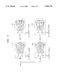
- FIG. 2 is a detailed block diagram of the video band pass filter (BPF), the audio BPF, the audio trap, and the video trap shown in FIG. 1; and
- FIG. 3 illustrates video and audio BPF characteristics of respective systems.
- a multi-receiving demodulator of the present invention has a tuner 105 for converting a radio frequency (RF) received via an antenna 102 to an intermediate frequency (IF), a video band pass filter (BPF) 110 for passing a color subcarrier from the intermediate frequency according to an M control signal, a video demodulating portion 120 for demodulating a video signal according to an L' control signal, an audio trap 130 for trapping an audio carrier according to the M control signal, an audio BPF 150 for passing the intermediate frequency of an audio carrier component from the intermediate frequency, an audio demodulating portion 160 for demodulating an audio signal according to the L' control signal, a video trap 170 for trapping the color subcarrier according to the M control signal, and a controller 190 for generating the M and L' control signals according to a power source frequency and channel selection data.
- RF radio frequency
- IF intermediate frequency
- BPF video band pass filter
- the tuner 105 shown in FIG. 1 tunes into a predetermined frequency from the radio frequency signal received via the antenna 102, mixes the tuned frequency with a local oscillating frequency generated in an internal oscillator, and outputs an intermediate frequency.
- the video BPF 110 and the audio BPF 150 band-pass-filter a color subcarrier and audio intermediate frequency from the intermediate frequency generated by the tuner 105.
- the video demodulating portion 120 and the audio demodulating portion 160 demodulate a carrier-free video signal and an audio signal by operating video and audio detections on the color subcarrier and the audio intermediate frequency received from the video BPF 110 and the audio BPF 150.
- the audio demodulating portion 160 includes a processor for processing AM and FM.
- the audio trap 130 suppresses interference with the video signal of the video demodulating portion 120 by trapping an audio carrier component for each broadcasting method
- the video trap 170 suppresses interference with the audio signal of the audio demodulating portion 160 by trapping a video carrier component for each broadcasting method.
- the controller 190 detects a power source frequency (60 Hz or 50 Hz) for each country. That is, the M control signal of the controller 190 becomes a high pulse signal for selecting the M system if the detected power source frequency is 60 Hz, and a low pulse signal for selecting the B/G, I, D/K, and L systems if the detected power source frequency is 50 Hz.
- the controller 190 generates the L' control signal by detecting a high-frequency band corresponding to a selected channel, using channel data stored in the controller 190. That is, the controlling portion 190 outputs the L' control signal being a high pulse signal if the detected high-frequency band is the VHF low band of the L system, and outputs the L' control signal being a low pulse signal if the detected high-frequency band is the B/G, M, D/K, or L (VHF high, and UHF) band.
- the video BPF 110 passes the color subcarrier (picture-color space (a): 3.58 MHz) of the M system as shown in table 1 if the M control signal is high, and the color subcarrier (picture-color space (a): 4.43 MHz) of the B/G, I, D/K, and L systems as shown in table 1 if the M control signal is low.
- the audio BPF 150 passes the intermediate frequency (40.9 MHz) of the audio carrier component of the VHF low band in the L system as shown in table 1, if the L' control signal is high, and the intermediate frequency (32.4-34.3 MHz) of the audio carrier component of the B/G, I, D/K, M, and (VHF high and UHF bands of) L systems if the L' control signal is low.
- detection is performed by a voltage controlled oscillator (VCO).
- the 34.4 MHz intermediate frequency (the VHF low band of the L system) as shown in table 1 is selected for the detection if the L' control signal is high, and the 38.9 MHz intermediate frequency (B/G, I, D/K, M, and VHF high and UHF bands of L) is selected if the L' control signal is low.
- detection is performed by a VCO.
- a 40.9 MHz intermediate frequency (the VHF low band of the L system) as shown in table 1 is selected for the detection if the L' control signal is high, and the 32.4-34.4 MHz intermediate frequency (B/G, I, D/K, M, and VHF high and UHF bands of L) is selected if the L' control signal is low.
- the audio trap 130 traps the picture-sound space of the M system as shown in table 1 if the M control signal is high, and that of the B/G, I, D/K, and L systems if the M control signal is low.
- the video trap 170 traps the picture-color space of the M system as shown in table 1 if the M control signal is high, and that of the B/G, I, D/K, and L systems if the M control signal is low.
- FIG. 2 is a detailed block diagram of the video BPF 110, the audio BPF 150, the audio trap 130 and the video trap 170.
- FIG. 3 illustrates video and audio BPF characteristics for each broadcasting system.
- f c denotes a color intermediate frequency
- f p denotes a picture intermediate frequency
- f s denotes a sound intermediate frequency.
- the video BPF 110 includes first and second BPFs 212 and 214.
- An intermediate frequency IF is selectively input to one of the first and second BPFs 212 and 214 according to the M control signal generated in the controller 190. For example, if the M control signal is high, a contact point (a) is connected to a contact point (H) and the intermediate frequency is input to the second BPF 214.
- the second BPF 214 passes only the 3.58 MHz(a) color subcarrier of the M system as in the second BPF(M) shown in FIG. 3.
- the M control signal is low, the contact point (a) is connected to a contact point (L), and the intermediate frequency is input to the first BPF 212.
- the first BPF 212 passes only the 4.43 MHz(a) color subcarrier of the B/G, I, D, D/K, and L systems as in the first BPF(B/G, I, D/K, L) shown in FIG. 3.
- the audio BPF 150 includes third and fourth BPFs 232 and 234.
- the intermediate frequency is selectively input to one of the third and fourth BPFs 232 and 234 according to the L' control signal generated in the controller 190.
- the L' control signal is high
- the contact point (a) is connected to the contact point (H) and the intermediate frequency is input to the fourth BPF 234.
- the fourth BPF 234 passes the intermediate frequency 40.9 MHz of an audio carrier component of the VHF low band in the L system as in the fourth BPF(L') shown in FIG. 3.
- the L' control signal is low
- the contact point (a) is connected to the contact point (L)
- the intermediate frequency is input to the third BPF 232.
- the third BPF 232 passes the intermediate frequency (32.4-34.4 MHz) of an audio carrier component in the B/G, I, D/K, L (VHF high and UHF) systems, as in the third BPF(B/G, I, D/K, L) shown in FIG. 3.
- the audio trap 130 includes first and second traps 222 and 224, and is controlled by the M control signal generated in the controller 190. That is, when the M control signal is high, the contact point (a) is connected to the contact point (H) and the second trap 224, which is a 4.5 MHz trap of the M system shown in table 1, is selected. If the M control signal is low, the contact point (a) is connected to the contact point (L) and the first trap 222, which is a 5.5-6.5 MHz trap of the B/G, I, D/K, and L systems shown in table 1, is selected.
- the video trap 170 includes third and fourth traps 242 and 244, and is controlled by the M control signal generated in the controller 190. That is, when the M control signal is high, the contact point (a) is connected to the contact point (H) and the fourth trap 244, which is a 3.58 MHz trap of the M system shown in table 1, is selected. On the other hand, if the M control signal is low, the third trap 242, which is a 4.43 MHz trap of the B/G, I, D/K, and L systems shown in table 1, is selected.
- the present invention can receive broadcasting signals from all over the world by employing multiple systems including M, I, B/G, D/K, and I systems.
Landscapes
- Engineering & Computer Science (AREA)
- Multimedia (AREA)
- Signal Processing (AREA)
- Power Engineering (AREA)
- Television Receiver Circuits (AREA)
- Circuits Of Receivers In General (AREA)
- Superheterodyne Receivers (AREA)
Applications Claiming Priority (2)
| Application Number | Priority Date | Filing Date | Title |
|---|---|---|---|
| KR1019970001307A KR100200647B1 (ko) | 1997-01-17 | 1997-01-17 | 멀티 수신 복조장치 |
| KR97-1307 | 1997-01-17 |
Publications (1)
| Publication Number | Publication Date |
|---|---|
| US6166776A true US6166776A (en) | 2000-12-26 |
Family
ID=19494944
Family Applications (1)
| Application Number | Title | Priority Date | Filing Date |
|---|---|---|---|
| US09/008,103 Expired - Lifetime US6166776A (en) | 1997-01-17 | 1998-01-16 | Multi-receiving demodulator for demodulating signals received from multiple broadcasting systems |
Country Status (3)
| Country | Link |
|---|---|
| US (1) | US6166776A (ko) |
| KR (1) | KR100200647B1 (ko) |
| DE (1) | DE19801527C2 (ko) |
Cited By (5)
| Publication number | Priority date | Publication date | Assignee | Title |
|---|---|---|---|---|
| US7227591B2 (en) * | 2002-11-01 | 2007-06-05 | Samsung Electronics Co., Ltd. | Apparatus and method for receiving television and radio broadcasting signals using a single tuner |
| WO2008032369A1 (fr) * | 2006-09-12 | 2008-03-20 | Panasonic Corporation | Dispositif terminal mobile |
| US20080211964A1 (en) * | 2005-04-08 | 2008-09-04 | Media Tek (Shenzhen) Inc. | Automatic Tv Standard Determination Method and Apparatus Thereof |
| US20090086107A1 (en) * | 2007-09-28 | 2009-04-02 | Intel Corporation | Reciever system for multiple bandwidth television channels |
| US20100045874A1 (en) * | 2005-01-28 | 2010-02-25 | Nxp B.V. | Intermediate frequency processing device for processing both analogue and digital television intermediate frequency signals |
Families Citing this family (2)
| Publication number | Priority date | Publication date | Assignee | Title |
|---|---|---|---|---|
| US6670997B1 (en) | 2000-11-15 | 2003-12-30 | Thomson Licensing S.A. | Autodetermination of appropriate television signal standard in a television signal receiver |
| KR100707826B1 (ko) * | 2006-06-05 | 2007-04-13 | 에스지씨테크놀로지 주식회사 | 멀티 밴드 패스필터 |
Citations (7)
| Publication number | Priority date | Publication date | Assignee | Title |
|---|---|---|---|---|
| US4688082A (en) * | 1984-05-23 | 1987-08-18 | Sharp Kabushiki Kaisha | Multi-system television receiver |
| US5355162A (en) * | 1993-07-13 | 1994-10-11 | Pacific Ray Video Limited | Multi-standard cable television system |
| US5467141A (en) * | 1992-02-20 | 1995-11-14 | Motorola, Inc. | Modulator circuit for use with a plurality of operating standards |
| US5663768A (en) * | 1994-06-09 | 1997-09-02 | Samsung Electronics Co., Ltd. | Multi-television broadcasting signal receiving apparatus and control method thereof |
| US5673088A (en) * | 1994-11-30 | 1997-09-30 | Samsung Electronics Co., Ltd. | Multi-broadcast selection apparatus |
| US5953072A (en) * | 1996-11-19 | 1999-09-14 | Daewoo Electronics Co., Ltd. | Apparatus for automatically switching broadcasting systems and a controlling method thereof |
| US5956098A (en) * | 1994-02-14 | 1999-09-21 | Hitachi, Ltd. | Digital broadcasting receiver |
Family Cites Families (3)
| Publication number | Priority date | Publication date | Assignee | Title |
|---|---|---|---|---|
| DE3737581A1 (de) * | 1987-11-05 | 1989-05-18 | Grundig Emv | Einrichtung zum automatischen anlegen der abgleichspannungen an die abstimmbaren schaltungselemente des zf-verstaerkers eines fernsehempfaengers |
| DE4012580A1 (de) * | 1990-04-20 | 1991-10-24 | Philips Patentverwaltung | Schaltungsanordnung zur erkennung der uebertragungsnorm eines farbfernsehsignals |
| DE4315230C2 (de) * | 1993-05-07 | 1996-03-21 | Grundig Emv | Fernsehempfänger zum Empfang und zur Wiedergabe von Fernsehsignalen mit unterschiedlichen Vertikalfrequenzen |
-
1997
- 1997-01-17 KR KR1019970001307A patent/KR100200647B1/ko not_active IP Right Cessation
-
1998
- 1998-01-16 DE DE19801527A patent/DE19801527C2/de not_active Expired - Fee Related
- 1998-01-16 US US09/008,103 patent/US6166776A/en not_active Expired - Lifetime
Patent Citations (7)
| Publication number | Priority date | Publication date | Assignee | Title |
|---|---|---|---|---|
| US4688082A (en) * | 1984-05-23 | 1987-08-18 | Sharp Kabushiki Kaisha | Multi-system television receiver |
| US5467141A (en) * | 1992-02-20 | 1995-11-14 | Motorola, Inc. | Modulator circuit for use with a plurality of operating standards |
| US5355162A (en) * | 1993-07-13 | 1994-10-11 | Pacific Ray Video Limited | Multi-standard cable television system |
| US5956098A (en) * | 1994-02-14 | 1999-09-21 | Hitachi, Ltd. | Digital broadcasting receiver |
| US5663768A (en) * | 1994-06-09 | 1997-09-02 | Samsung Electronics Co., Ltd. | Multi-television broadcasting signal receiving apparatus and control method thereof |
| US5673088A (en) * | 1994-11-30 | 1997-09-30 | Samsung Electronics Co., Ltd. | Multi-broadcast selection apparatus |
| US5953072A (en) * | 1996-11-19 | 1999-09-14 | Daewoo Electronics Co., Ltd. | Apparatus for automatically switching broadcasting systems and a controlling method thereof |
Cited By (10)
| Publication number | Priority date | Publication date | Assignee | Title |
|---|---|---|---|---|
| US7227591B2 (en) * | 2002-11-01 | 2007-06-05 | Samsung Electronics Co., Ltd. | Apparatus and method for receiving television and radio broadcasting signals using a single tuner |
| US20100045874A1 (en) * | 2005-01-28 | 2010-02-25 | Nxp B.V. | Intermediate frequency processing device for processing both analogue and digital television intermediate frequency signals |
| US8614769B2 (en) | 2005-01-28 | 2013-12-24 | Nxp, B.V. | Intermediate frequency processing device for processing both analogue and digital television intermediate frequency signals |
| US20080211964A1 (en) * | 2005-04-08 | 2008-09-04 | Media Tek (Shenzhen) Inc. | Automatic Tv Standard Determination Method and Apparatus Thereof |
| WO2008032369A1 (fr) * | 2006-09-12 | 2008-03-20 | Panasonic Corporation | Dispositif terminal mobile |
| US20100041432A1 (en) * | 2006-09-12 | 2010-02-18 | Panasonic Corporation | Mobile terminal device |
| JP4879990B2 (ja) * | 2006-09-12 | 2012-02-22 | パナソニック株式会社 | 携帯端末装置 |
| US8271027B2 (en) | 2006-09-12 | 2012-09-18 | Panasonic Corporation | Mobile terminal device |
| US20090086107A1 (en) * | 2007-09-28 | 2009-04-02 | Intel Corporation | Reciever system for multiple bandwidth television channels |
| US8237870B2 (en) * | 2007-09-28 | 2012-08-07 | Intel Corporation | Receiver system for multiple bandwidth television channels |
Also Published As
| Publication number | Publication date |
|---|---|
| DE19801527C2 (de) | 2003-10-02 |
| KR19980066006A (ko) | 1998-10-15 |
| DE19801527A1 (de) | 1998-07-23 |
| KR100200647B1 (ko) | 1999-06-15 |
Similar Documents
| Publication | Publication Date | Title |
|---|---|---|
| KR0157413B1 (ko) | 지상 am 및 위성 fm-tv 방송 신호 수신기 | |
| KR920002046B1 (ko) | 수신장치 | |
| US7330707B2 (en) | Hetrodyne receiver and IC | |
| KR20020008050A (ko) | 텔레비젼 수신 장치 | |
| US7034898B1 (en) | Mobile television receiver | |
| US6166776A (en) | Multi-receiving demodulator for demodulating signals received from multiple broadcasting systems | |
| CA1212465A (en) | Frequency translation phase-locked loop for separate or intercarrier type television sound detection | |
| JP4628624B2 (ja) | オフセットチューニング手段を有するデジタル信号のためのテレビジョン受信機 | |
| US7239358B1 (en) | Television receiver for digital signals with offset tuning provisions | |
| KR890000648B1 (ko) | 텔레비젼 음성신호 수신기 | |
| US6046775A (en) | Recovering data from a vestigial sideband of a standard television signal | |
| GB2325804A (en) | Combined satellite and CATV receiver | |
| JP3128371B2 (ja) | 受信装置 | |
| JP3288251B2 (ja) | Catv受信装置 | |
| KR0174913B1 (ko) | 세캄 컬러의 왜곡을 보상하는 장치 | |
| JPH07162771A (ja) | 映像中間周波処理装置 | |
| JPH06189220A (ja) | 放送受信装置 | |
| JP2514014B2 (ja) | L−secam方式テレビジヨン信号の音声検波装置 | |
| JP3038280B2 (ja) | 受信装置 | |
| JPS6367031A (ja) | 受信装置 | |
| JP2820713B2 (ja) | ダブルコンバージョンチューナ | |
| JP3360364B2 (ja) | バランス出力型チューナ装置の中間周波処理回路 | |
| JP2002135668A (ja) | ディジタル放送受信装置 | |
| JPH0450707Y2 (ko) | ||
| JP2880223B2 (ja) | テレビジョン受信機 |
Legal Events
| Date | Code | Title | Description |
|---|---|---|---|
| AS | Assignment |
Owner name: SAMSUNG ELECTRONICS CO., LTD., KOREA, REPUBLIC OF Free format text: ASSIGNMENT OF ASSIGNORS INTEREST;ASSIGNOR:MOON, BYOUNG-CHO;REEL/FRAME:009242/0631 Effective date: 19980310 |
|
| STCF | Information on status: patent grant |
Free format text: PATENTED CASE |
|
| FPAY | Fee payment |
Year of fee payment: 4 |
|
| FPAY | Fee payment |
Year of fee payment: 8 |
|
| FEPP | Fee payment procedure |
Free format text: PAYOR NUMBER ASSIGNED (ORIGINAL EVENT CODE: ASPN); ENTITY STATUS OF PATENT OWNER: LARGE ENTITY |
|
| FPAY | Fee payment |
Year of fee payment: 12 |