US6152684A - Method for operation of hydraulic turbine - Google Patents
Method for operation of hydraulic turbine Download PDFInfo
- Publication number
- US6152684A US6152684A US09/063,599 US6359998A US6152684A US 6152684 A US6152684 A US 6152684A US 6359998 A US6359998 A US 6359998A US 6152684 A US6152684 A US 6152684A
- Authority
- US
- United States
- Prior art keywords
- cavitation
- machine
- characteristic value
- operating
- value
- Prior art date
- Legal status (The legal status is an assumption and is not a legal conclusion. Google has not performed a legal analysis and makes no representation as to the accuracy of the status listed.)
- Expired - Lifetime
Links
- 238000000034 method Methods 0.000 title claims abstract description 38
- 230000008569 process Effects 0.000 claims abstract description 26
- XLYOFNOQVPJJNP-UHFFFAOYSA-N water Substances O XLYOFNOQVPJJNP-UHFFFAOYSA-N 0.000 claims abstract description 24
- 239000004576 sand Substances 0.000 claims abstract description 15
- 238000012545 processing Methods 0.000 claims abstract description 10
- 238000012937 correction Methods 0.000 claims description 14
- 230000001105 regulatory effect Effects 0.000 claims description 12
- 238000010586 diagram Methods 0.000 claims description 10
- 238000011144 upstream manufacturing Methods 0.000 claims description 6
- 238000004422 calculation algorithm Methods 0.000 claims description 3
- 238000005457 optimization Methods 0.000 claims description 3
- 238000004804 winding Methods 0.000 abstract description 2
- 238000005259 measurement Methods 0.000 description 12
- 230000033228 biological regulation Effects 0.000 description 6
- 230000003628 erosive effect Effects 0.000 description 6
- 238000011156 evaluation Methods 0.000 description 6
- 238000012360 testing method Methods 0.000 description 5
- 230000000694 effects Effects 0.000 description 3
- 238000009434 installation Methods 0.000 description 3
- 230000009471 action Effects 0.000 description 2
- 230000003321 amplification Effects 0.000 description 2
- 238000004458 analytical method Methods 0.000 description 2
- 238000001514 detection method Methods 0.000 description 2
- 238000001914 filtration Methods 0.000 description 2
- 239000000463 material Substances 0.000 description 2
- 238000012544 monitoring process Methods 0.000 description 2
- 238000003199 nucleic acid amplification method Methods 0.000 description 2
- 230000002250 progressing effect Effects 0.000 description 2
- 238000007670 refining Methods 0.000 description 2
- 238000004092 self-diagnosis Methods 0.000 description 2
- 230000009469 supplementation Effects 0.000 description 2
- VVQNEPGJFQJSBK-UHFFFAOYSA-N Methyl methacrylate Chemical compound COC(=O)C(C)=C VVQNEPGJFQJSBK-UHFFFAOYSA-N 0.000 description 1
- 229920005372 Plexiglas® Polymers 0.000 description 1
- 230000004913 activation Effects 0.000 description 1
- 238000007792 addition Methods 0.000 description 1
- 230000015572 biosynthetic process Effects 0.000 description 1
- 230000009172 bursting Effects 0.000 description 1
- 238000004364 calculation method Methods 0.000 description 1
- 230000001914 calming effect Effects 0.000 description 1
- 230000008859 change Effects 0.000 description 1
- 238000005352 clarification Methods 0.000 description 1
- 238000004590 computer program Methods 0.000 description 1
- 238000012790 confirmation Methods 0.000 description 1
- 230000009849 deactivation Effects 0.000 description 1
- 230000003247 decreasing effect Effects 0.000 description 1
- 230000007547 defect Effects 0.000 description 1
- 238000013461 design Methods 0.000 description 1
- 238000003745 diagnosis Methods 0.000 description 1
- 238000005265 energy consumption Methods 0.000 description 1
- 238000005516 engineering process Methods 0.000 description 1
- 230000009931 harmful effect Effects 0.000 description 1
- 230000010354 integration Effects 0.000 description 1
- JEIPFZHSYJVQDO-UHFFFAOYSA-N iron(III) oxide Inorganic materials O=[Fe]O[Fe]=O JEIPFZHSYJVQDO-UHFFFAOYSA-N 0.000 description 1
- 230000000670 limiting effect Effects 0.000 description 1
- 238000011022 operating instruction Methods 0.000 description 1
- 230000036961 partial effect Effects 0.000 description 1
- 230000002829 reductive effect Effects 0.000 description 1
- 230000003014 reinforcing effect Effects 0.000 description 1
- 230000008439 repair process Effects 0.000 description 1
- 230000004044 response Effects 0.000 description 1
- 238000012552 review Methods 0.000 description 1
- 239000013049 sediment Substances 0.000 description 1
- 230000003068 static effect Effects 0.000 description 1
- 230000001629 suppression Effects 0.000 description 1
- 230000036962 time dependent Effects 0.000 description 1
- 230000007704 transition Effects 0.000 description 1
- 230000000007 visual effect Effects 0.000 description 1
Images
Classifications
-
- F—MECHANICAL ENGINEERING; LIGHTING; HEATING; WEAPONS; BLASTING
- F03—MACHINES OR ENGINES FOR LIQUIDS; WIND, SPRING, OR WEIGHT MOTORS; PRODUCING MECHANICAL POWER OR A REACTIVE PROPULSIVE THRUST, NOT OTHERWISE PROVIDED FOR
- F03B—MACHINES OR ENGINES FOR LIQUIDS
- F03B15/00—Controlling
- F03B15/02—Controlling by varying liquid flow
- F03B15/04—Controlling by varying liquid flow of turbines
- F03B15/06—Regulating, i.e. acting automatically
-
- F—MECHANICAL ENGINEERING; LIGHTING; HEATING; WEAPONS; BLASTING
- F03—MACHINES OR ENGINES FOR LIQUIDS; WIND, SPRING, OR WEIGHT MOTORS; PRODUCING MECHANICAL POWER OR A REACTIVE PROPULSIVE THRUST, NOT OTHERWISE PROVIDED FOR
- F03B—MACHINES OR ENGINES FOR LIQUIDS
- F03B11/00—Parts or details not provided for in, or of interest apart from, the preceding groups, e.g. wear-protection couplings, between turbine and generator
- F03B11/04—Parts or details not provided for in, or of interest apart from, the preceding groups, e.g. wear-protection couplings, between turbine and generator for diminishing cavitation or vibration, e.g. balancing
-
- F—MECHANICAL ENGINEERING; LIGHTING; HEATING; WEAPONS; BLASTING
- F03—MACHINES OR ENGINES FOR LIQUIDS; WIND, SPRING, OR WEIGHT MOTORS; PRODUCING MECHANICAL POWER OR A REACTIVE PROPULSIVE THRUST, NOT OTHERWISE PROVIDED FOR
- F03B—MACHINES OR ENGINES FOR LIQUIDS
- F03B15/00—Controlling
- F03B15/02—Controlling by varying liquid flow
- F03B15/04—Controlling by varying liquid flow of turbines
- F03B15/06—Regulating, i.e. acting automatically
- F03B15/16—Regulating, i.e. acting automatically by power output
-
- Y—GENERAL TAGGING OF NEW TECHNOLOGICAL DEVELOPMENTS; GENERAL TAGGING OF CROSS-SECTIONAL TECHNOLOGIES SPANNING OVER SEVERAL SECTIONS OF THE IPC; TECHNICAL SUBJECTS COVERED BY FORMER USPC CROSS-REFERENCE ART COLLECTIONS [XRACs] AND DIGESTS
- Y02—TECHNOLOGIES OR APPLICATIONS FOR MITIGATION OR ADAPTATION AGAINST CLIMATE CHANGE
- Y02E—REDUCTION OF GREENHOUSE GAS [GHG] EMISSIONS, RELATED TO ENERGY GENERATION, TRANSMISSION OR DISTRIBUTION
- Y02E10/00—Energy generation through renewable energy sources
- Y02E10/20—Hydro energy
Definitions
- the invention relates to a process for operating a hydraulic machine, in particular a hydro-turbine.
- the cavitation limits ascertained in the model case converted for the large execution are deposited in the turbine regulator.
- this takes place in the form of characteristic curves, the maximally possible flow being taken as a function of the drop height.
- the maximal opening of the regulating unit greaterest setting angle of the guide vanes.
- the maximally allowable flow is defined by a characteristic curve family as a function of drop height and tailwater level.
- the regulator with the aid of these characteristic curves limits the regulating unit and therewith the flow through the machine, so that the admissible limit values cannot in any case be exceeded.
- a further refinement is yielded by the consideration of the influence of the tailwater level on the cavitation limits, i.e. the maximally allowable flow is defined by the characteristic curve family as a function of drop height and tailwater level.
- the regulator limits the regulating unit and therewith the flow through the machine, so that the allowable limit values can in no case be exceeded.
- the cavitation limit values determined in advance by model test and calculation in advance are given firmly once and for all. They do not, therefore, take into account changes that set in during the life of the machine as well as during the life of the entire installation. These changes affect, for example, the geometric contour of the flow-conducting parts (for example of the guide vanes and of the runner blades), or changes that result by reason of sand erosion, rust, repairs, etc. in the course of time, but also changes in the inflow conditions of the machine (for example structural changes, sand banks in the flow bed, changed level of the tailwater level, etc.).
- Characteristic value 1 represents the sum effective value of the high-pass filtered time signal. This characteristic value permits a quantitative statement about the cavitation load.
- Characteristic value 2 is a number signal.
- the evaluating apparatus here counts the peaks over a pre-defined time window, in which each peak represents the action of a bursting cavitation bubble. This characteristic value is well suited for the detection of the cavitation onset, because at first it rises very steeply and with fully developed cavitation it goes over into a saturation range.
- Underlying the invention is the problem of giving a process for the operating of a hydraulic machine, which makes it possible, during the operation of the large machine, to detect the cavitation limits as exactly as possible, so that, on the one hand, cavitation safety is given to a still higher degree and that, on the other hand, there is obtained a maximal utilization of the machine performance.
- the invention it is proposed, therefore, to detect the actual state of the machine during operation, in order automatically to extend the operating range of the machine so that machine treatment and maximizing of the energy generation as well as a flexible operation guidance can be optimally attuned to one another.
- the operation guidance a working point is prescribed within a critical zone (therefore within a range which in solutions of hitherto was deliberately excluded from the outset), the setting magnitude is automatically regulated in such manner that on the machine, just barely still, no dangerous erosion occurs.
- the statements about the cavitation behavior of the machine are based essentially on measured cavitation characteristic values. With the aid of characteristic data that are derived from the machine model, therewith, an evaluation is also possible (type of cavitation, harmful effect). By inclusion of further state characterizing values these statements can be further confirmed.
- a further feature of the invention is the optimization of the air infeed.
- cavitating turbulences in the blade channel and in the suction pipe lead to a rough behavior of the machine with disagreeable side effects (rumbling, shaft vibrations, building vibrations, etc.).
- the compressor needed for the generation of the blast air needed in certain cases has a relatively great energy consumption.
- Generator temperature (for example winding temperature)
- the process is not restricted to the recounted measurement data.
- the system can call upon further-characteristic values for the refining of the evaluation, or for the confirmation of the indications. Furthermore, not all of the signals mentioned are required for the application of the process. Lacking characteristic values are replaced by standard assumptions (experience values) or calculated with the aid of the machine model.
- the invention can also be used on old machines for which no model data are present. In regard to old machines, in many cases it is even the sole possibility for obtaining dependable indications about the admissible operating range.
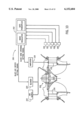
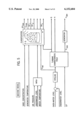
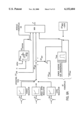
- FIG. 2 shows a large overview of the integration of the "PowerPlus” module into a digital turbine regulator
- FIG. 3 shows a schematic representation of the structure of the "PowerPlus” module
- FIG. 4 shows a schematic representation of the measurement value processing
- FIG. 5 shows a schematic representation of the machine model used to determine the hydraulic operating point of the machine
- FIG. 6b shows a Q-H or P-H diagram for further refining the classification by the consideration of the sand content in the medium
- FIG. 7a shows a schematic representation of the functions of the performance control
- FIG. 7b shows a second branch of the performance control for optimizing the blast-air infeed in dependence on the cavitation state for arrangements in which the blast-air is switched on/off;
- FIG. 7c shows a second variant of the second branch of FIG. 7b for arrangements in which the blast-air amount can be controlled quantitatively;
- FIG. 8a shows a cut-out from the block structure of the turbine regulator for clarifying the tying-in of the results of "PowerPlus";
- FIG. 8b shows a second variant of the block structure of the turbine regulator shown in FIG. 8a, which provides for suppressing only the correction signal;
- FIGS. 9a-9c are flow charts illustrating exemplary process steps for operating a hydraulic machine and system in accordance with certain aspects of the invention.
- FIG. 10 shows a schematic representation of the digital turbine regulator and integrated "PowerPlus" module associated with a turbine suitable for practicing the present invention.
- FIG. 2 first of all explains, in a large overview, how the module "PowerPlus” is integrated into a digital turbine regulator.
- the block designated basis regulator presents there the largely unaltered regulator in the form of hitherto.
- the realization of "PowerPlus” as an integral component of the digital turbine regulator allows an optimal embedding of the extended functions as supplementation to the traditional regulator functions.
- SPS external apparatus
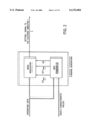
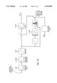
- the structure of the module "PowerPlus” is shown in FIG. 3.
- the operating data input magnitudes and the state characteristic values are first worked up in the measurement value preliminary processing.
- the result, the measurement vector m is represented as a double arrow to clarify the fact that here it is a matter of a field of several magnitudes.
- the basic data are formed for optimal performance.
- the measurement value vector m and the evaluating vector a are fed, besides to the regulator, to the data logger module, and to the message generation and intrinsic diagnosis modules.
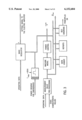
- the measurement value processing is schematically represented.
- operating data and state characteristic values are worked up for further processing in the other submodules.
- the measurement values there can come directly from sensors or it can be a matter of already pre-processed data (for example cavitation characteristic values, vibration characteristic values).
- the type of evaluation is governed according to the characteristic value. This can be a filtering, a frequency analysis, but also an arithmetic linkage of different characteristic values.
- FIG. 5 shows the schematic structure of the machine model.
- the machine model serves for one thing to determine the hydraulic operating point of the machine, characterized by flow or performance, by the net drop height and by the NPSH value. This takes place in the block pipe line, turbine characteristic field, generator and NPSH.
- the NPSH value net positive suction head
- the NPSH value is calculated from tailwater level, air pressure and water temperature. It describes the distance of the static pressure from the vapor pressure of the medium and it influences, therefore, the cavitation danger and therewith the limits of the admissible operating range.
- the configuration represented presents merely an example for the evaluation which is carried out on the basis of the typically present measurement and model data.
- the machine model can be structured entirely differently.
- the generator performance P gen is usable instead of the guide vane opening ⁇ .
- the aim is in each case the determination of the hydraulic working point of the machine, which makes possible a classification and evaluation of the measured cavitation characteristic values.
- P-H diagram turbine performance
- the inner curve bounds the range which, without additional monitoring measures, can be regarded as safe. This is the limit which in solutions of hitherto was to be observed, either forced by the automatic system or forced by the operating instructions of the machine manufacturer. In between there is located the above-addressed "gray zone", in which the automatic performance optimization becomes effective.
- the performance limit prescribed by the thermal overload limit of the generator as well as the limitation of the setting unit.
- the performance limit of the generator can optionally be followed up in dependence on temperature.
- a further refinement of the classification can be achieved by the consideration of the sand content in the medium (FIG. 6b). This is associated with the fact that in certain operating ranges, the erosion danger increases clearly with increasing sand content.
- the performance control takes this into consideration in the manner that, if the corresponding characteristic value indicates increased sand content, the evaluation of the cavitation characteristic values is altered in such manner that these zones are avoided.
- FIG. 7a is a schematic representation of the functions of the performance control.
- the performance control calculates a sign-affected correction value ⁇ korr which is added to the setting signal.
- the arrangement presents essentially a regulator with arbitrary dynamic properties, which sets the working point of the machine so that the cavitation characteristic value 1 lies below a settable threshold value.
- a limiter for reasons of safety, the engagement possibility of "PowerPlus” can be limited.
- the filter prevents abrupt changes of performance.
- a mathematical logic is provided which switches in the engagement of "PowerPlus” only after run-off of a time delay. This is required inter alia since certain zones, especially in the partial load range must necessarily be run through in operating transitions.
- FIG. 7b shows a second branch of the performance control. This optimizes the blast-air infeed in dependence on the cavitation state.
- the system on the basis of the cavitation characteristic value 2, renders the decision as to when the blast-air infeed is switched on; i.e., a binary signal is derived for the decision blast-air on/off. If the cavitation characteristic value 2 exceeds a settable threshold value, then if the signal Ort ⁇
- the filter serves for the suppression of brief peaks, while the hysteresis block prevents excessively frequent switchings on and off of the blast air infeed.
- the second variant (FIG. 7c) is meant for arrangements in which the blast-air amount can be controlled quantitatively (for example over a choke valve).
- the blast-air amount can be controlled quantitatively (for example over a choke valve).
- a proportional member instead of the hysteresis member, there is provided a proportional member.
- the amount of air is influenced over the cavitation behavior and, namely, so that increasing cavitation leads to an increase of the amount of air.
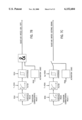
- FIG. 8a shows, for the clarification of the tying-in of the results of "PowerPlus", a cut-out from the block structure of the turbine regulator.
- the regulating algorithm belonging to the momentary active operating type (performance regulation, water state regulation, turning-rate regulation etc.) delivers the desired value for the setting signal ⁇ soll .
- the sign-affected correction value ⁇ korr determined by "PowerPlus” is added.
- the block MIN there then occurs a minimal value selection.
- a further limitation is activated if the self-diagnosis of "PowerPlus” ascertains that the system does not operate correctly. By closing of the logical switch provided for this eventuality a firmly predetermined curve family becomes active,
- the correction signal can also be summed up for the regulating difference at the input of the regulator for the individual operating types. Furthermore there is present the possibility that the minimal selection between ⁇ korr and ⁇ max occurs already in the module "PowerPlus" and the minimum of the two magnitudes is switched onto the block MIN of the regulator.
- a further engagement possibility is provided for the activation of a power reserve for a limited span of time.
- a limitation of the operating range is deliberately dispensed with. In this mode and for a settable time, material loss by cavitation erosion is deliberately accepted into the bargain in favor of the fulfillment of a superordinated purpose.
- the output to the electrical amplifier is controlled for the time t max in such manner that the setting member opens the guide vanes up to the mechanical limit. All the limitations are disregarded for this period of time.
- a second variant (FIG. 8b) provides for suppressing only the correction signal.
- the predetermined limitation over ⁇ max (outer absolute limitation of the operating range), however, is active as before.
- FIG. 3 further blocks are drawn in, which blocks further process the data which are generated by the above-described functions.
- the block Data logger makes possible a gap-free documentation of the machine state.
- the data base generated here can be used externally with suitable computer programs in order to detect and to evaluate longer-term changes on the machine or installation.
- the correlation between the measurement data and the material removals observed in reviews permits a calibration of the cavitation characteristic values.
- the block Report documents all happenings and the interventions of the module, and thus makes the functioning manner of "PowerPlus” transparent to the user.
- the block self-diagnosis uses redundant information data (for example measurement, model computation) in order, with the aid of plausibility tests, to recheck the functions of "PowerPlus” and of the measuring technique. As soon as inconsistencies are detected there immediately occurs, besides a report, the automatic deactivation of the module.
- redundant information data for example measurement, model computation
- the components necessary for the realization of the invention may be integral components of the turbine regulator. It is obvious that the measured state characteristic values in general do not yet suffice to use the process of the invention. On the contrary, it is necessary to classify the machine model in order to determine the type of cavitation for the machine concerned. It is to be ascertained, therefore, whether it is a matter of surface cavitation, suction-side and pressure-side entry cavitation, or of cavitation turbulences.
- FIGS. 9a-9c represent exemplary process steps implemented by the above-described and illustrated digital turbine regulator including the "PowerPlus" module integrated therein.
- FIG. 9a represents exemplary steps of a process for operating a hydraulic machine to reduce cavitation and/or quiet running
- FIG. 9b represents exemplary steps for classifying and evaluating characteristic values for use in the process of FIG. 9a
- FIG. 9c represents exemplary steps for determining a correction value and altering the gate opening for use in the process of FIG. 9a.
- the "PowerPlus" process begins at step 102 wherein the main process loop is implemented by the regulator of FIG. 2.
- the regulator determines the actual machine state during operation of the turbine by ascertaining operating data through the use of sensors.
- the operating data ascertained during this step includes flow through the machine, effective and reactive power fed into electric mains, guide vane opening, pressure upstream of the machine and at a suction pipe exit, headwater level, and tailwater or lower water level.
- the regulator processes one or more state characteristic values in step 106.
- the state characteristic values may include any/all of a first cavitation characteristic value, a second cavitation characteristic value, vibration characteristic values, suction pipe pressure, sand concentration, air pressure, water temperature, and generator temperature.
- the operating data input magnitudes and state characteristic value(s) are inputted to the filtering, frequency analysis block of FIG. 4 to produce the measurement vector m.
- step 108 the hydraulic operating point of the machine, characterized by flow performance, by the net drop head, and by the NPSH value, is determined by the machine model of FIG. 5. Based on the hydraulic working point of the machine, the measured cavitation characteristic values are classified and evaluated to determine the danger of cavitation along with the admissible operating range of the machine.
- step 110 the sensed and/or processed characteristic values are classified and evaluated. As illustrated in FIG. 9b, step 110 preferably comprises a number of substeps 112-116.
- step 112 based on the present operating point of the turbine in a Q-H diagram for the given NPSH, the cavitation is classified according to type or place of cavitation, e.g., pressure-side onset edge cavitation, suction-side onset edge cavitation, surface cavitation, cavitation channel turbulence, etc.
- step 114 the performance limit prescribed by the thermal overload limit of the generator, as well as the limitation of the setting unit (maximal guide vane opening), are taken into account.
- step 116 the classification is further refined by taking into consideration the sand content in the medium (see FIG. 6b).
- step 118 preferably comprises a number of substeps 120-128.
- the regulating algorithm belonging to the momentary active operating type (performance regulation, water state regulation, turning-rate regulation, etc.) delivers the desired value for the setting signal ⁇ soll .
- a sign-affected correction value ⁇ korr is determined to result in the turbine operating point being such that the first cavitation characteristic value lies below a settable threshold value. Step 124 then adds this correction value to the setting signal by way of the summation circuit shown in FIG. 8a.
- step 126 the block MIN shown in FIG. 8a performs a minimal value selection between this summed value ( ⁇ soll + ⁇ korr ), the maximum correction value ( ⁇ korrmax ) (if it is determined by "PowerPlus” that the system does not operate correctly), the absolute maximum gate opening value ( ⁇ max ) (which may be set at 100% of the mechanical limit at the expense of cavitation loss for a settable time period to activate a power reserve).
- This minimum value (L) is then used to change the width of the guide vane opening in step 128.
- the blast-air infeed is optimized in step 130 in dependence on the cavitation state to calm turbulences or vibrations appearing in the machine.
- the blast-air may be optimized either in a switched on/off manner (using the performance control branch illustrated in FIG. 7b) or in a quantitatively controlled manner (using the performance control branch illustrated in FIG. 7c).
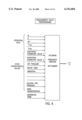
- FIG. 10 shows a schematic representation of the "PowerPlus” system 200 including a digital turbine regulator 202 (which, as illustrated, is provided with the integrated "PowerPlus” module) associated with an exemplary turbine 204 suitable for practicing the present invention.
- the system also includes a plurality of sensors 206-214 for acquiring the actual operating data.
- turbine 204 includes a plurality of guide vanes 216 that are adjustable in position by the regulator to control the flow of water passing through the turbine. The amount of opening of guide vanes 216 is controlled by setting signals that are generated by turbine regulator 202 (and amplified by an electric amplifier 218) in accordance with the exemplary method described above.
- the system also includes a blower 220 and air supply 222 which are controlled by the digital regulator in the manner described above.
Landscapes
- Engineering & Computer Science (AREA)
- Chemical & Material Sciences (AREA)
- Combustion & Propulsion (AREA)
- Mechanical Engineering (AREA)
- General Engineering & Computer Science (AREA)
- Hydraulic Turbines (AREA)
Applications Claiming Priority (2)
| Application Number | Priority Date | Filing Date | Title |
|---|---|---|---|
| DE19719406 | 1997-05-12 | ||
| DE19719406A DE19719406C1 (de) | 1997-05-12 | 1997-05-12 | Verfahren zum Betreiben einer hydraulischen Maschine |
Publications (1)
| Publication Number | Publication Date |
|---|---|
| US6152684A true US6152684A (en) | 2000-11-28 |
Family
ID=7828966
Family Applications (1)
| Application Number | Title | Priority Date | Filing Date |
|---|---|---|---|
| US09/063,599 Expired - Lifetime US6152684A (en) | 1997-05-12 | 1998-04-21 | Method for operation of hydraulic turbine |
Country Status (4)
| Country | Link |
|---|---|
| US (1) | US6152684A (pt) |
| EP (1) | EP0878624A1 (pt) |
| BR (1) | BR9802084A (pt) |
| DE (1) | DE19719406C1 (pt) |
Cited By (20)
| Publication number | Priority date | Publication date | Assignee | Title |
|---|---|---|---|---|
| US20020123856A1 (en) * | 2001-03-01 | 2002-09-05 | Evren Eryurek | Cavitation detection in a process plant |
| WO2003083291A1 (de) * | 2002-03-28 | 2003-10-09 | Va Tech Hydro Gmbh & Co. | Stauanlage mit heb-und senkbaren turbinen-generatormodul |
| US20040115047A1 (en) * | 2001-10-11 | 2004-06-17 | Michel Sabourin | Hydraulic turbine with increased power capacities |
| US6814543B2 (en) | 2002-12-30 | 2004-11-09 | General Electric Company | Method and apparatus for bucket natural frequency tuning |
| WO2009065189A1 (en) * | 2007-11-23 | 2009-05-28 | Atlantis Resources Corporation Pte Limited | Control system for extracting power from water flow |
| US20110083230A1 (en) * | 2005-09-16 | 2011-04-07 | Bridgestone Corporation | Gene cluster involved in biosynthesis of isopentenyl diphosphate in the non-mevalonate pathway of hevea brasiliensis |
| US20110176915A1 (en) * | 2008-04-14 | 2011-07-21 | Atlantis Resources Corporation Pte Ltd. | Blade for a water turbine |
| US20120235416A1 (en) * | 2009-11-09 | 2012-09-20 | Technische Universitat Munchen | Shaft power plant |
| US8314507B2 (en) | 2010-04-21 | 2012-11-20 | Kiser Hydro, Llc | Hydro unit retrofit and method of performing same |
| US8633609B2 (en) | 2008-04-14 | 2014-01-21 | Atlantis Resources Corporation Pte Limited | Sub sea central axis turbine with rearwardly raked blades |
| US8664790B2 (en) | 2009-04-28 | 2014-03-04 | Atlantis Resources Corporation Pte Limited | Underwater power generator with dual blade sets |
| US8920200B2 (en) | 2009-10-27 | 2014-12-30 | Atlantis Resources Corporation Pte | Connector for mounting an underwater power generator |
| WO2015162043A3 (en) * | 2014-04-23 | 2015-12-10 | Alstom Renewable Technologies | Sediment concentration monitoring system for water turbines |
| US20170254313A1 (en) * | 2014-09-15 | 2017-09-07 | Alstom Renewable Technologies | Method for determining the operating point of a hydraulic machine and installation for converting hydraulic energy |
| JP2018040595A (ja) * | 2016-09-05 | 2018-03-15 | 株式会社東芝 | 水力機械の壊食予測装置および予測方法 |
| CN113155266A (zh) * | 2021-03-08 | 2021-07-23 | 西安理工大学 | 综合振动测试和压力脉动测试的水轮机空化初生判定方法 |
| US11280310B2 (en) * | 2017-03-29 | 2022-03-22 | Voith Patent Gmbh | Hydraulic machine having a device for measuring the water level in the intake pipe and method for drainage |
| AT525441A4 (de) * | 2022-03-25 | 2023-04-15 | Andritz Hydro Gmbh | Hydraulische maschine mit ueberwachungssystem |
| JP2023150581A (ja) * | 2022-03-31 | 2023-10-16 | ダイキン工業株式会社 | 水力発電システム |
| US12196169B2 (en) | 2020-08-31 | 2025-01-14 | Tmv Detections Oy | Hydro turbine with reduced cavitation |
Families Citing this family (4)
| Publication number | Priority date | Publication date | Assignee | Title |
|---|---|---|---|---|
| DE19906123B4 (de) * | 1999-02-13 | 2004-06-24 | Voith Siemens Hydro Power Generation Gmbh & Co. Kg | Verfahren zur Vergrößerung des Arbeitsbereiches von geführten Strömungen |
| FR2913730A1 (fr) * | 2007-03-12 | 2008-09-19 | Alstom Technology Ltd | Installation hydraulique et procede de commande d'une telle installation |
| DE102011107286A1 (de) * | 2011-07-06 | 2013-01-10 | Voith Patent Gmbh | Strömungskraftwerk und Verfahren für dessen Betrieb |
| CN120740924B (zh) * | 2025-09-02 | 2025-12-05 | 浙江工业大学 | 可测量过机含沙量的抽水蓄能模型试验装置及其试验方法 |
Citations (30)
| Publication number | Priority date | Publication date | Assignee | Title |
|---|---|---|---|---|
| US3174719A (en) * | 1962-06-12 | 1965-03-23 | Dominion Eng Works Ltd | Francis turbines and centrifugal pumps |
| US3188050A (en) * | 1963-06-19 | 1965-06-08 | Dominion Eng Works Ltd | Seals for turbo-machinery |
| US3236499A (en) * | 1964-06-05 | 1966-02-22 | Dominion Eng Works Ltd | Differential pressure control of sealing fluid for rotary fluid machines |
| US3405913A (en) * | 1967-12-04 | 1968-10-15 | Dominion Eng Works Ltd | Rotary seal structure |
| US3677659A (en) * | 1970-07-31 | 1972-07-18 | Worthington Corp | Multi-stage pump and components therefor |
| US4003671A (en) * | 1973-12-04 | 1977-01-18 | Norges Skipsforskningsinstitutt | Method and means to prevent cavitation erosion in propeller ducts |
| US4014624A (en) * | 1974-08-16 | 1977-03-29 | Hitachi, Ltd. | Method and device for starting pump |
| US4022423A (en) * | 1975-07-30 | 1977-05-10 | Kieley & Mueller, Inc. | Control valve |
| US4217077A (en) * | 1977-02-21 | 1980-08-12 | Titovi Zavodi Litostroj Ljubljana N.Sol.O. | Two-stage/single-stage reversible pump-turbine with supplying pump |
| US4236867A (en) * | 1979-07-27 | 1980-12-02 | The United States Of America As Represented By The Secretary Of The Navy | Friction reducing arrangement for hydraulic machines |
| US4278051A (en) * | 1978-04-05 | 1981-07-14 | Hitachi, Ltd. | Method of preventing recirculation pump cavitation and forced recirculation pump type steam-generating apparatus using the method |
| US4431370A (en) * | 1980-11-07 | 1984-02-14 | Tokyo Shibaura Denki Kabushiki Kaisha | Multistage hydraulic machines having air exhausting devices |
| US4475865A (en) * | 1981-01-30 | 1984-10-09 | Tokyo Shibaura Denki Kabushiki Kaisha | Apparatus for controlling the operation of a water turbine or a pump turbine and a method thereof |
| US4674279A (en) * | 1984-09-12 | 1987-06-23 | Acres International Corporation | Control system for run-of-river hydroelectric plant |
| US4780051A (en) * | 1985-05-23 | 1988-10-25 | Voith Hydro, Inc. | Hydraulic turbine aeration apparatus |
| US4794544A (en) * | 1987-03-26 | 1988-12-27 | Woodward Governor Company | Method and apparatus for automatically index testing a kaplan turbine |
| US4806781A (en) * | 1986-01-17 | 1989-02-21 | Siemens Aktiengesellschaft | Water-driven machine set with the speed reference value set for optimum efficiency |
| US4823018A (en) * | 1986-05-12 | 1989-04-18 | Hitachi Ltd. | Control system for variable speed water-wheel generator apparatus |
| US4920277A (en) * | 1987-08-14 | 1990-04-24 | Hitachi, Ltd. | Control system for a variable speed hydro-power plant apparatus |
| US5322412A (en) * | 1991-05-22 | 1994-06-21 | Sulzer Escher Wyss Ag, | Method and apparatus for optimizing the operating parameters of a double-regulated water turbine |
| US5402332A (en) * | 1992-06-23 | 1995-03-28 | J.M. Voith Gmbh | Method for optimizing the efficiency of a set of machines comprising a turbine and a generator |
| US5441384A (en) * | 1993-10-15 | 1995-08-15 | Hydro West Group, Inc. | Hydraulic turbine and guide gate apparatus and runner apparatus therefor |
| US5742515A (en) * | 1995-04-21 | 1998-04-21 | General Electric Co. | Asynchronous conversion method and apparatus for use with variable speed turbine hydroelectric generation |
| US5754446A (en) * | 1996-08-19 | 1998-05-19 | Voith Hydro, Inc. | Method and apparatus for optimizing performance of a kaplan turbine |
| US5780935A (en) * | 1996-12-26 | 1998-07-14 | Iowa State University Research Foundation, Inc. | Hydropowered turbine system |
| US5864183A (en) * | 1996-08-28 | 1999-01-26 | Voith Hydro, Inc. | Method and apparatus for optimizing performance of a pump-turbine |
| US5941682A (en) * | 1997-07-24 | 1999-08-24 | Voith Hydro, Inc. | Draft tube peripheral plenum |
| US5947680A (en) * | 1995-09-08 | 1999-09-07 | Ebara Corporation | Turbomachinery with variable-angle fluid guiding vanes |
| US5947679A (en) * | 1996-03-28 | 1999-09-07 | Voith Hydro, Inc. | Adjustable blade turbines |
| US5954474A (en) * | 1996-03-28 | 1999-09-21 | Voith Hydro, Inc. | Hydro-turbine runner |
Family Cites Families (1)
| Publication number | Priority date | Publication date | Assignee | Title |
|---|---|---|---|---|
| JPS6153465A (ja) * | 1984-08-22 | 1986-03-17 | Kansai Electric Power Co Inc:The | 水車の停止方法 |
-
1997
- 1997-05-12 DE DE19719406A patent/DE19719406C1/de not_active Expired - Fee Related
-
1998
- 1998-04-21 US US09/063,599 patent/US6152684A/en not_active Expired - Lifetime
- 1998-05-02 EP EP98108023A patent/EP0878624A1/de not_active Withdrawn
- 1998-05-12 BR BR9802084A patent/BR9802084A/pt not_active IP Right Cessation
Patent Citations (30)
| Publication number | Priority date | Publication date | Assignee | Title |
|---|---|---|---|---|
| US3174719A (en) * | 1962-06-12 | 1965-03-23 | Dominion Eng Works Ltd | Francis turbines and centrifugal pumps |
| US3188050A (en) * | 1963-06-19 | 1965-06-08 | Dominion Eng Works Ltd | Seals for turbo-machinery |
| US3236499A (en) * | 1964-06-05 | 1966-02-22 | Dominion Eng Works Ltd | Differential pressure control of sealing fluid for rotary fluid machines |
| US3405913A (en) * | 1967-12-04 | 1968-10-15 | Dominion Eng Works Ltd | Rotary seal structure |
| US3677659A (en) * | 1970-07-31 | 1972-07-18 | Worthington Corp | Multi-stage pump and components therefor |
| US4003671A (en) * | 1973-12-04 | 1977-01-18 | Norges Skipsforskningsinstitutt | Method and means to prevent cavitation erosion in propeller ducts |
| US4014624A (en) * | 1974-08-16 | 1977-03-29 | Hitachi, Ltd. | Method and device for starting pump |
| US4022423A (en) * | 1975-07-30 | 1977-05-10 | Kieley & Mueller, Inc. | Control valve |
| US4217077A (en) * | 1977-02-21 | 1980-08-12 | Titovi Zavodi Litostroj Ljubljana N.Sol.O. | Two-stage/single-stage reversible pump-turbine with supplying pump |
| US4278051A (en) * | 1978-04-05 | 1981-07-14 | Hitachi, Ltd. | Method of preventing recirculation pump cavitation and forced recirculation pump type steam-generating apparatus using the method |
| US4236867A (en) * | 1979-07-27 | 1980-12-02 | The United States Of America As Represented By The Secretary Of The Navy | Friction reducing arrangement for hydraulic machines |
| US4431370A (en) * | 1980-11-07 | 1984-02-14 | Tokyo Shibaura Denki Kabushiki Kaisha | Multistage hydraulic machines having air exhausting devices |
| US4475865A (en) * | 1981-01-30 | 1984-10-09 | Tokyo Shibaura Denki Kabushiki Kaisha | Apparatus for controlling the operation of a water turbine or a pump turbine and a method thereof |
| US4674279A (en) * | 1984-09-12 | 1987-06-23 | Acres International Corporation | Control system for run-of-river hydroelectric plant |
| US4780051A (en) * | 1985-05-23 | 1988-10-25 | Voith Hydro, Inc. | Hydraulic turbine aeration apparatus |
| US4806781A (en) * | 1986-01-17 | 1989-02-21 | Siemens Aktiengesellschaft | Water-driven machine set with the speed reference value set for optimum efficiency |
| US4823018A (en) * | 1986-05-12 | 1989-04-18 | Hitachi Ltd. | Control system for variable speed water-wheel generator apparatus |
| US4794544A (en) * | 1987-03-26 | 1988-12-27 | Woodward Governor Company | Method and apparatus for automatically index testing a kaplan turbine |
| US4920277A (en) * | 1987-08-14 | 1990-04-24 | Hitachi, Ltd. | Control system for a variable speed hydro-power plant apparatus |
| US5322412A (en) * | 1991-05-22 | 1994-06-21 | Sulzer Escher Wyss Ag, | Method and apparatus for optimizing the operating parameters of a double-regulated water turbine |
| US5402332A (en) * | 1992-06-23 | 1995-03-28 | J.M. Voith Gmbh | Method for optimizing the efficiency of a set of machines comprising a turbine and a generator |
| US5441384A (en) * | 1993-10-15 | 1995-08-15 | Hydro West Group, Inc. | Hydraulic turbine and guide gate apparatus and runner apparatus therefor |
| US5742515A (en) * | 1995-04-21 | 1998-04-21 | General Electric Co. | Asynchronous conversion method and apparatus for use with variable speed turbine hydroelectric generation |
| US5947680A (en) * | 1995-09-08 | 1999-09-07 | Ebara Corporation | Turbomachinery with variable-angle fluid guiding vanes |
| US5947679A (en) * | 1996-03-28 | 1999-09-07 | Voith Hydro, Inc. | Adjustable blade turbines |
| US5954474A (en) * | 1996-03-28 | 1999-09-21 | Voith Hydro, Inc. | Hydro-turbine runner |
| US5754446A (en) * | 1996-08-19 | 1998-05-19 | Voith Hydro, Inc. | Method and apparatus for optimizing performance of a kaplan turbine |
| US5864183A (en) * | 1996-08-28 | 1999-01-26 | Voith Hydro, Inc. | Method and apparatus for optimizing performance of a pump-turbine |
| US5780935A (en) * | 1996-12-26 | 1998-07-14 | Iowa State University Research Foundation, Inc. | Hydropowered turbine system |
| US5941682A (en) * | 1997-07-24 | 1999-08-24 | Voith Hydro, Inc. | Draft tube peripheral plenum |
Non-Patent Citations (3)
| Title |
|---|
| Experience With An Acoustic Cavitation Monitor For Water Turbines article from ImechE 1992 (5 pgs.). * |
| Technische Universitat Wien 8. Internationales Seminar Wasserkraftanlagen; Nov. 1994 (13 pgs.). * |
| Technische Universitat Wien--8. Internationales Seminar Wasserkraftanlagen; Nov. 1994 (13 pgs.). |
Cited By (32)
| Publication number | Priority date | Publication date | Assignee | Title |
|---|---|---|---|---|
| US20020123856A1 (en) * | 2001-03-01 | 2002-09-05 | Evren Eryurek | Cavitation detection in a process plant |
| WO2002071168A1 (en) * | 2001-03-01 | 2002-09-12 | Fisher-Rosemount Systems, Inc. | Cavitation detection in a process plant |
| US6954713B2 (en) | 2001-03-01 | 2005-10-11 | Fisher-Rosemount Systems, Inc. | Cavitation detection in a process plant |
| CN1324418C (zh) * | 2001-03-01 | 2007-07-04 | 费舍-柔斯芒特系统股份有限公司 | 制炼系统内使用的气穴检测 |
| US20040115047A1 (en) * | 2001-10-11 | 2004-06-17 | Michel Sabourin | Hydraulic turbine with increased power capacities |
| US6926494B2 (en) | 2001-10-11 | 2005-08-09 | Alstom Canada Inc. | Hydraulic turbine with increased power capacities |
| WO2003083291A1 (de) * | 2002-03-28 | 2003-10-09 | Va Tech Hydro Gmbh & Co. | Stauanlage mit heb-und senkbaren turbinen-generatormodul |
| US6814543B2 (en) | 2002-12-30 | 2004-11-09 | General Electric Company | Method and apparatus for bucket natural frequency tuning |
| US20110083230A1 (en) * | 2005-09-16 | 2011-04-07 | Bridgestone Corporation | Gene cluster involved in biosynthesis of isopentenyl diphosphate in the non-mevalonate pathway of hevea brasiliensis |
| WO2009065189A1 (en) * | 2007-11-23 | 2009-05-28 | Atlantis Resources Corporation Pte Limited | Control system for extracting power from water flow |
| US8801386B2 (en) | 2008-04-14 | 2014-08-12 | Atlantis Resources Corporation Pte Limited | Blade for a water turbine |
| US8633609B2 (en) | 2008-04-14 | 2014-01-21 | Atlantis Resources Corporation Pte Limited | Sub sea central axis turbine with rearwardly raked blades |
| US20110176915A1 (en) * | 2008-04-14 | 2011-07-21 | Atlantis Resources Corporation Pte Ltd. | Blade for a water turbine |
| US8664790B2 (en) | 2009-04-28 | 2014-03-04 | Atlantis Resources Corporation Pte Limited | Underwater power generator with dual blade sets |
| US8920200B2 (en) | 2009-10-27 | 2014-12-30 | Atlantis Resources Corporation Pte | Connector for mounting an underwater power generator |
| US8648487B2 (en) * | 2009-11-09 | 2014-02-11 | Technische Universität München | Shaft power plant |
| US20120235416A1 (en) * | 2009-11-09 | 2012-09-20 | Technische Universitat Munchen | Shaft power plant |
| US8314507B2 (en) | 2010-04-21 | 2012-11-20 | Kiser Hydro, Llc | Hydro unit retrofit and method of performing same |
| WO2015162043A3 (en) * | 2014-04-23 | 2015-12-10 | Alstom Renewable Technologies | Sediment concentration monitoring system for water turbines |
| US20170114768A1 (en) * | 2014-04-23 | 2017-04-27 | General Electric Technology Gmbh | Hydraulic installation and method of operating such an installation |
| US10294914B2 (en) * | 2014-04-23 | 2019-05-21 | Ge Renewable Technologies | Hydraulic installation and method of operating such an installation |
| US10598145B2 (en) * | 2014-09-15 | 2020-03-24 | Ge Renewable Technologies | Method for determining the operating point of a hydraulic machine and installation for converting hydraulic energy |
| US20170254313A1 (en) * | 2014-09-15 | 2017-09-07 | Alstom Renewable Technologies | Method for determining the operating point of a hydraulic machine and installation for converting hydraulic energy |
| JP2018040595A (ja) * | 2016-09-05 | 2018-03-15 | 株式会社東芝 | 水力機械の壊食予測装置および予測方法 |
| US11280310B2 (en) * | 2017-03-29 | 2022-03-22 | Voith Patent Gmbh | Hydraulic machine having a device for measuring the water level in the intake pipe and method for drainage |
| US12196169B2 (en) | 2020-08-31 | 2025-01-14 | Tmv Detections Oy | Hydro turbine with reduced cavitation |
| US12416284B2 (en) | 2020-08-31 | 2025-09-16 | Tmv Detections Oy | Measurement arrangement for hydro turbine |
| CN113155266A (zh) * | 2021-03-08 | 2021-07-23 | 西安理工大学 | 综合振动测试和压力脉动测试的水轮机空化初生判定方法 |
| CN113155266B (zh) * | 2021-03-08 | 2022-11-01 | 西安理工大学 | 综合振动测试和压力脉动测试的水轮机空化初生判定方法 |
| AT525441A4 (de) * | 2022-03-25 | 2023-04-15 | Andritz Hydro Gmbh | Hydraulische maschine mit ueberwachungssystem |
| AT525441B1 (de) * | 2022-03-25 | 2023-04-15 | Andritz Hydro Gmbh | Hydraulische maschine mit ueberwachungssystem |
| JP2023150581A (ja) * | 2022-03-31 | 2023-10-16 | ダイキン工業株式会社 | 水力発電システム |
Also Published As
| Publication number | Publication date |
|---|---|
| DE19719406C1 (de) | 1998-11-19 |
| EP0878624A1 (de) | 1998-11-18 |
| BR9802084A (pt) | 1999-07-06 |
Similar Documents
| Publication | Publication Date | Title |
|---|---|---|
| US6152684A (en) | Method for operation of hydraulic turbine | |
| US6709241B2 (en) | Apparatus and method for controlling a pump system | |
| CA1267692A (en) | Vane angle adjustment method of controlling operation of hydro turbine | |
| US5332356A (en) | Process and a device for determining the erosion caused by cavitation in components through which fluid flows | |
| WO2021012884A1 (zh) | 自动排空水泵的控制方法、装置相应设备及存储介质 | |
| CN109312760A (zh) | 泵的监测 | |
| EP3187735A1 (en) | Pump system as well as a method for determining the flow in a pump system | |
| Ahonen | Monitoring of centrifugal pump operation by a frequency converter | |
| EP3559445B1 (en) | Wind turbine temperature dependent noise reduction | |
| Cucit et al. | A control system for preventing cavitation of centrifugal pumps | |
| EP0278226B1 (en) | Method and apparatus for detecting pressure surges in a turbo-compressor | |
| CN109154289B (zh) | 用于识别抽吸气的方法 | |
| RU2766499C2 (ru) | Способ эксплуатации циркуляционного насоса, а также циркуляционный насос для осуществления этого способа | |
| US20250109730A1 (en) | Method and system for monitoring operation of hydraulic turbine under extremely low water head | |
| US6742534B2 (en) | Method of damping surges in a liquid system | |
| JP2003269313A (ja) | 水車又はポンプ水車のキャビテーション壊食回避運転方法及びキャビテーション壊食量推定方法並びにそのプログラム | |
| RU2493437C1 (ru) | Система управления турбоагрегатом | |
| CN114790991A (zh) | 给水泵汽蚀检测系统及方法 | |
| CN114837964A (zh) | 一种竖井贯流泵自动避振区运行的方法 | |
| RU2498115C1 (ru) | Система оптимального управления турбоагрегатом | |
| CN121349029A (zh) | 一种基于控制模型的生物氧化过程智能优化方法 | |
| Attivissimo et al. | Model based control and diagnostic system for centrifugal pumps | |
| CN121184844A (zh) | 油烟机的控制方法、装置及电子设备 | |
| JP3524130B2 (ja) | 水力機械およびその運転状態監視方法 | |
| JPS59137609A (ja) | 油圧回路の油量異常検出装置 |
Legal Events
| Date | Code | Title | Description |
|---|---|---|---|
| AS | Assignment |
Owner name: VOITH HYDRO, INC., PENNSYLVANIA Free format text: ASSIGNMENT OF ASSIGNORS INTEREST;ASSIGNORS:KOPF, EBERHARD;FERME, JEAN-MARC;KLEIN, JOACHIM;REEL/FRAME:009533/0636;SIGNING DATES FROM 19980917 TO 19981005 |
|
| STCF | Information on status: patent grant |
Free format text: PATENTED CASE |
|
| FPAY | Fee payment |
Year of fee payment: 4 |
|
| FPAY | Fee payment |
Year of fee payment: 8 |
|
| FPAY | Fee payment |
Year of fee payment: 12 |