EP3187735A1 - Pump system as well as a method for determining the flow in a pump system - Google Patents
Pump system as well as a method for determining the flow in a pump system Download PDFInfo
- Publication number
- EP3187735A1 EP3187735A1 EP15202953.4A EP15202953A EP3187735A1 EP 3187735 A1 EP3187735 A1 EP 3187735A1 EP 15202953 A EP15202953 A EP 15202953A EP 3187735 A1 EP3187735 A1 EP 3187735A1
- Authority
- EP
- European Patent Office
- Prior art keywords
- pump
- sub
- model
- flow
- fluid container
- Prior art date
- Legal status (The legal status is an assumption and is not a legal conclusion. Google has not performed a legal analysis and makes no representation as to the accuracy of the status listed.)
- Granted
Links
- 238000000034 method Methods 0.000 title claims description 12
- 239000012530 fluid Substances 0.000 claims abstract description 89
- 238000011156 evaluation Methods 0.000 claims abstract description 59
- 230000006399 behavior Effects 0.000 claims description 41
- 230000006870 function Effects 0.000 claims description 10
- 241001125929 Trisopterus luscus Species 0.000 claims description 4
- 238000001514 detection method Methods 0.000 claims description 4
- XLYOFNOQVPJJNP-UHFFFAOYSA-N water Substances O XLYOFNOQVPJJNP-UHFFFAOYSA-N 0.000 description 8
- 230000001419 dependent effect Effects 0.000 description 6
- 239000002351 wastewater Substances 0.000 description 5
- 230000006978 adaptation Effects 0.000 description 4
- 238000005259 measurement Methods 0.000 description 4
- 230000002123 temporal effect Effects 0.000 description 4
- 238000011109 contamination Methods 0.000 description 3
- 238000013461 design Methods 0.000 description 3
- 238000010586 diagram Methods 0.000 description 3
- 230000005484 gravity Effects 0.000 description 3
- 230000002706 hydrostatic effect Effects 0.000 description 3
- 238000009434 installation Methods 0.000 description 2
- 238000005086 pumping Methods 0.000 description 2
- 238000013459 approach Methods 0.000 description 1
- 125000004122 cyclic group Chemical group 0.000 description 1
- 239000007788 liquid Substances 0.000 description 1
- 230000000630 rising effect Effects 0.000 description 1
- 238000011144 upstream manufacturing Methods 0.000 description 1
Images


Classifications
-
- G—PHYSICS
- G01—MEASURING; TESTING
- G01F—MEASURING VOLUME, VOLUME FLOW, MASS FLOW OR LIQUID LEVEL; METERING BY VOLUME
- G01F1/00—Measuring the volume flow or mass flow of fluid or fluent solid material wherein the fluid passes through a meter in a continuous flow
- G01F1/05—Measuring the volume flow or mass flow of fluid or fluent solid material wherein the fluid passes through a meter in a continuous flow by using mechanical effects
- G01F1/34—Measuring the volume flow or mass flow of fluid or fluent solid material wherein the fluid passes through a meter in a continuous flow by using mechanical effects by measuring pressure or differential pressure
-
- E—FIXED CONSTRUCTIONS
- E03—WATER SUPPLY; SEWERAGE
- E03F—SEWERS; CESSPOOLS
- E03F5/00—Sewerage structures
- E03F5/10—Collecting-tanks; Equalising-tanks for regulating the run-off; Laying-up basins
- E03F5/105—Accessories, e.g. flow regulators or cleaning devices
-
- F—MECHANICAL ENGINEERING; LIGHTING; HEATING; WEAPONS; BLASTING
- F04—POSITIVE - DISPLACEMENT MACHINES FOR LIQUIDS; PUMPS FOR LIQUIDS OR ELASTIC FLUIDS
- F04D—NON-POSITIVE-DISPLACEMENT PUMPS
- F04D13/00—Pumping installations or systems
- F04D13/02—Units comprising pumps and their driving means
- F04D13/06—Units comprising pumps and their driving means the pump being electrically driven
-
- F—MECHANICAL ENGINEERING; LIGHTING; HEATING; WEAPONS; BLASTING
- F04—POSITIVE - DISPLACEMENT MACHINES FOR LIQUIDS; PUMPS FOR LIQUIDS OR ELASTIC FLUIDS
- F04D—NON-POSITIVE-DISPLACEMENT PUMPS
- F04D13/00—Pumping installations or systems
- F04D13/16—Pumping installations or systems with storage reservoirs
-
- F—MECHANICAL ENGINEERING; LIGHTING; HEATING; WEAPONS; BLASTING
- F04—POSITIVE - DISPLACEMENT MACHINES FOR LIQUIDS; PUMPS FOR LIQUIDS OR ELASTIC FLUIDS
- F04D—NON-POSITIVE-DISPLACEMENT PUMPS
- F04D15/00—Control, e.g. regulation, of pumps, pumping installations or systems
-
- F—MECHANICAL ENGINEERING; LIGHTING; HEATING; WEAPONS; BLASTING
- F04—POSITIVE - DISPLACEMENT MACHINES FOR LIQUIDS; PUMPS FOR LIQUIDS OR ELASTIC FLUIDS
- F04D—NON-POSITIVE-DISPLACEMENT PUMPS
- F04D15/00—Control, e.g. regulation, of pumps, pumping installations or systems
- F04D15/0088—Testing machines
-
- E—FIXED CONSTRUCTIONS
- E03—WATER SUPPLY; SEWERAGE
- E03F—SEWERS; CESSPOOLS
- E03F2201/00—Details, devices or methods not otherwise provided for
- E03F2201/20—Measuring flow in sewer systems
-
- F—MECHANICAL ENGINEERING; LIGHTING; HEATING; WEAPONS; BLASTING
- F05—INDEXING SCHEMES RELATING TO ENGINES OR PUMPS IN VARIOUS SUBCLASSES OF CLASSES F01-F04
- F05D—INDEXING SCHEME FOR ASPECTS RELATING TO NON-POSITIVE-DISPLACEMENT MACHINES OR ENGINES, GAS-TURBINES OR JET-PROPULSION PLANTS
- F05D2260/00—Function
- F05D2260/81—Modelling or simulation
-
- F—MECHANICAL ENGINEERING; LIGHTING; HEATING; WEAPONS; BLASTING
- F05—INDEXING SCHEMES RELATING TO ENGINES OR PUMPS IN VARIOUS SUBCLASSES OF CLASSES F01-F04
- F05D—INDEXING SCHEME FOR ASPECTS RELATING TO NON-POSITIVE-DISPLACEMENT MACHINES OR ENGINES, GAS-TURBINES OR JET-PROPULSION PLANTS
- F05D2260/00—Function
- F05D2260/82—Forecasts
- F05D2260/821—Parameter estimation or prediction
Definitions
- the invention relates to a pump system as well as to a method for determining the flow in a pump system.
- Pump systems which comprise a fluid container for storing the fluid to be pumped out or the pumped in fluid are known.
- the fluid level fluctuates in such fluid containers. It is difficult to determine the actual throughflow or exit flow for this reason, since the delivery flow of the pump does not always correspond the throughflow.
- GB 2 221 073 discloses a method which is based on time measurements on filling and emptying a fluid tank. This method has the disadvantage that it only functions when the inflow into the fluid container is essentially constant during the pumping. As a rule, this is not the case.
- EP 2 258 949 discloses a method for estimating the flow (throughflow) in a pump system with a fluid container, said method applying a routine for calibration, which is based on the assumption that the inflow into the container is essentially constant during the pumping. Thereby, an average value before switching on the pump forms a basis for the inflow.
- This method however is also not reliable, in particular if several pumps with several fluid containers are connected in series.
- the pump system comprises at least one fluid container with an inlet and with an outlet.
- the fluid to be delivered flows through the inlet into the fluid container and out of this again through the outlet.
- the pump system comprises at least one pump which can be arranged in the inlet or the outlet. This means that the fluid container can be arranged upstream or downstream of the pump in the flow direction.
- waste-water systems for example, it is known for the waste-water to be delivered to firstly flow into a pump sump representing the fluid container, and being delivered out of this with the help of the pump, out of the outlet.
- water supply systems it is known for example for the pump to deliver the water into a fluid container which is situated at a higher level.
- the pump delivers the fluid through the inlet into the fluid container.
- the fluid can flow away out of the fluid container again, due to gravity for example.
- the pump system moreover comprises a control device having a flow evaluation device designed to determine or identify the parameters of a flow model describing the flow through the container of the pump system, i.e. the inlet and the exit flow, and to do continuously flow estimation based on the identified parameters of the flow model.
- the flow evaluation device for this is designed in a manner such that a system model is applied for determining the parameters of the flow model.
- the system model which simulates the complete pump system with the fluid container consists of at least two sub-models.
- a first of the sub-models describes the inflow behaviour of the container and a second sub-model describes the outflow behaviour of the container, i.e. the outward flow through the outlet.
- the exit-side flow or exit flow can be determined or estimated via the second sub-model.
- the sub-models are designed such that they can determine or output the desired flow values continuously on the basis of previously determined model parameters and input variables measured in the system.
- the two different sub-models are preferably of a different or varying nature. This means that they are preferably independent of one another and have a different behaviour as a reaction to the input parameters. Thus for example the one sub-model is not in the position of assuming the behaviour of the other sub-model or being dependent on the behaviour of the second sub-model. An independent description of the inflow behaviour and of the outflow behaviour out of the container can be achieved in this manner.
- control device comprises memory means, which are designed to store measurement values (readings) or data, which are/is detected in the pump system.
- the control device moreover preferably comprises a parameter evaluation device which is designed to determine parameters or model parameters of the at least two sub-models on the basis of the stored data. This means that the models are adapted on the basis of the measured and stored data by way of determining their parameters, so that they describe the system or part-system as accurately as possible.
- the parameter evaluation device is preferably designed in a manner such that the parameters of the first sub-model and the parameters of the second sub-model can be simultaneously determined. Further preferably, the parameter evaluation by way of the parameter evaluation device can be effected simultaneously with the flow estimation in the flow evaluation device.
- the control device permits a continuous evaluation of the flow with a simultaneous continuous adaptation or optimisation of the sub-models, on the basis of which the flow model parameter evaluation (identification) is effected.
- the parameter evaluation device determines the model parameters on a cyclic base, e.g. a set of data is collected and used for determining a new set of model parameters.
- the flow evaluation device uses a former set of model parameter for continuously estimating the flow, when a new set of data is collected, the parameter evaluation device determines a new set of model parameters,
- the parameter evaluation device is designed such that the parameters for both part models are always evaluated, even if later only one of the sub-models is used for determining the flow.
- the sub-model which describes the outflow behaviour is preferably used for determining the flow.
- the other sub-model then serves as an auxiliary model which merely serves for the parameter evaluation of both sub-models.
- the parameter evaluation device is further preferably designed such that the parameters of the at least two sub-models are determined by error minimisation between an estimated output variable which is determined by the sub-models, and a corresponding output variable which has been measured or calculated from measurements done in the system.
- This in particular can be effected by way of applying the least-mean-squares method.
- the estimated output variable which is determined by the models is compared to actual output variable, and the parameters of the sub-models are adapted such that the estimated variable differs as little as possible from the actual output variable.
- the sub-models are therefore adapted such that they describe the system as optimally as possible.
- the described error minimisation can be effected simultaneously for both sub-models, for example by way of a sum or a difference of the two sub-models being formed and being compared to an actual output variable.
- the actual output variable can thereby correspond to the fluid level or the height of the fluid in the fluid container or its change over time.
- the change must thereby correspond to the difference between the inflow and the outflow out of the fluid container, and this can be determined from the two sub-models.
- the fluid container is provided with a level sensor which detects the fluid level in the inside of the container, wherein the detected fluid level is stored as part of the acquired data, i.e. is stored in the previously described memory means.
- the stored fluid level i.e. in particular the temporal course of the fluid level can then serve as a basis for determining the parameters of the sub-models, in the parameter evaluation device.
- the level or fluid level can thereby be determined in a direct or indirect manner, for example by way of a pressure sensor which determines the hydrostatic pressure.
- the at least one pump comprises an electrical drive motor and a power detection device, which detects the current (prevailing) electrical power of the drive motor, wherein the electric power is stored as part of the detected data, i.e. is stored in the previously described memory means.
- a power detection device which detects the current (prevailing) electrical power of the drive motor, wherein the electric power is stored as part of the detected data, i.e. is stored in the previously described memory means.
- the detected electrical power over time is thus preferably stored in the memory means, since the power detection is preferably detected in a continuous manner.
- a pressure sensor is further preferably arranged at the outlet side of the pump and detects the outlet pressure of the pump, wherein the outlet pressure is stored as part of the acquired data, i.e. is stored in the previously described memory means.
- the parameter evaluation device can thus fall back on stored pressure values, in order to determine the parameters of the sub-models.
- the pressure sensor preferably detects the pressure in a continuous manner and a temporal course of the outlet pressure is stored in the memory means.
- control device is designed in a manner such that it detects the number of active pumps in the pump system and/or the rotation speed of the at least one pump, wherein preferably the number of active pumps and/or the rotation speed is stored as a part of the acquired, which is to say detected data, i.e. is stored in the previously described memory means or the described memory device.
- the parameter evaluation device can thus fall back on the number of active pumps or the rotation speed, in order to determine the parameters of the sub-models.
- a temporal course of the number of active pumps and/or of the rotation speed can preferably be stored in the memory means or the memory device.
- the first sub-model is a function of time and of at least one determined model parameter.
- the model parameter is determined in the described manner by way of the parameter evaluation device.
- the second sub-model is preferably a function of a data which is detected in the system, e.g. of the data to be stored and of at least one determined model parameter.
- model parameters which are determined by the previously described parameter evaluation device which is to say are preferably continuously adapted.
- the data it can be the case for example of the output variable corresponding to the fluid level, the electrical power of the drive motor, the exit pressure of the pump, the number of active pumps in the pump system and/or the rotation speed of one or more pumps, as previously described. If the first sub-model is a function of time and the second sub-model is a function of the measured data, then the outputs estimated by these two sub-models are different with regard to their nature and independent of one another, as has been described above as a preferred design.
- the control device is further preferably designed such that the second sub-model is applied in order to determine the pump flow or the flow through the fluid container.
- the second part model as described above, is the part model which preferably describes the outflow behaviour of the container. This is particularly the case if the pump is arranged in the outlet of the fluid container.
- the first sub-model preferably describes the inflow behaviour into the fluid container. If conversely, the pump is arranged in the inlet or intake of the fluid container, then the second sub-model which describes the pump flow describes or represents the inflow behaviour into the fluid container, whereas the first sub-model describes or represents the outflow behaviour.
- the flow through the fluid container preferably represents the flow in the outlet of the fluid container, so that in this case the first sub-model can then be used for determining the flow through the fluid container.
- the control device is accordingly adapted in these cases.
- the fluid container is a pump sump and the pump is arranged in an outlet, in order to pump fluid out of the pump sump, wherein the first sub-model describes the inflow into the pump sump and the second sub-model the behaviour of the pump, i.e. the outflow behaviour of the fluid container.
- the pump it can preferably be the case of submersible pump, which is immersed into the pump sump.
- the second sub-model is preferably used in order to determine the flow or the hydraulic delivery flow of the pump via the model.
- the continuous calibration of the sub-models by way of adapting their parameters by way of the parameter evaluation device is advantageous with such a pump system, since with waste-water pumps for example, the efficiency of the pump can rapidly change over time due to contamination and wear.
- the flow evaluation device according to the invention has the advantage that it continuously calibrates itself, wherein fluctuating inlet flows are also taken into account via the first sub-model.
- the pump can be arranged in the inlet, in order to fill the container, wherein the first sub-model describes the outflow out of the container and the second sub-model describes the behaviour of the pump, i.e. the inflow behaviour.
- the first sub-model can be used to determine the exit flow or the flow through the fluid container.
- Such an arrangement for example can be applied with the supply of water, with which water is pumped via the pump into a fluid container which is situated at a higher location, from which it can flow out again solely on account of gravity.
- a change of the system characteristics due to wear or contamination can be taken into account by way of continuous calibration or adaptation of the parameters of the sub-models.
- the subject-matter of the invention apart from the previously described pump system, is a pump flow evaluation method, which can be applied for example in the previously described pump system.
- the pump flow evaluation method serves for determining the flow which is to say the outlet flow of a pump system, wherein the pump system comprises at least one pump and a fluid container.
- the pump system can preferably correspond to the pump system according to the preceding description.
- the method is characterised in that the outlet flow is determined by a system model which consists of at least two sub-models, a sub-model which describes the inflow behaviour of the fluid container and a sub-model which describes the outflow behaviour or the outlet flow of the fluid container.
- the evaluation of the flow is thereby effected in a manner as has been described beforehand by way of the pump system.
- the features which are described by way of the pump system thereby likewise represent preferred features of the pump flow evaluation method according to the invention.
- the preceding description is referred to inasmuch as this is concerned.
- the pump flow evaluation method in the system model preferably applies as least two sub-models which are of a different nature to the extent that they have a different behaviour as a reaction to a change of input values.
- the two sub-models do not influence one another, and it is possible to continuously adapt the parameters of the system model in a manner such that the system model describes the inflow behaviour as well as the outflow behaviour out of the fluid container.
- the second sub-model is used continuously for a flow estimation. e.g.
- the pump system according to the invention can be designed as a system for delivering waste water.
- Fig. 1 shows a corresponding arrangement.
- a pump sump 2 forms a fluid container, which is provided with an inlet 4 and with an outlet 6.
- the inlet 4 is situated on the upper side and the outlet 6 on the lower side of the pump sump 2.
- a pump 8 which delivers water or liquid out of the pump sump 2 is arranged on the outlet 6.
- the pump 8 is arranged outside the pump sump 2.
- a submersible pump however could also be applied.
- There are several relevant variables in such a pump system specifically the inlet flow q in and the outlet flow q p , wherein the outlet flow q p corresponds to the delivery flow of the pump 8.
- the first pressure sensor 10 forms a level sensor.
- the pressure sensor 10 is arranged in the inside of the pump sump 2, for detecting the hydrostatic pressure at the base of the pump stump 2.
- the level h of the fluid in the inside of the pump sump 2 can be determined from the hydrostatic pressure in the known manner.
- the pressure sensor 12 is arranged in the outlet 6 or the outlet conduit downstream of the pump 8, i.e. on the delivery side of the pump 8 and detects the outlet pressure pout of the pump 8.
- a further variable which is relevant to the system is the electrical power consumption P of the electrical drive motor 14 of the pump 8.
- the pump 8 preferably comprises n integrated control device 16 which receives sensor signals from the pressure sensors 10 and 12 and also detects the electric power consumption P of the drive motor 14.
- the control device 16 can additionally control the electric drive motor 14 of the pump 8.
- the control device 16 moreover comprises a flow evaluation device and by way of this is in the position of determining the flows q in and q p .
- this control device 16 can be an external device especially if there are two or more pumps in the system.
- This flow evaluation device 18 is represented schematically in Fig. 2 .
- the flow evaluation device uses a system model 20 simulating the pump system, for the computation or for the approximate evaluation of the flows q p and q in .
- the system model 20 consists of two sub-models 22 and 24, whose function is described in more detail further below.
- the flow evaluation device 18 further comprises a data acquisition module 26 which continuously acquires or detects measured system parameters, in this example the height h of the fluid level in the pump sump 2 which is computed on the basis of the signal of the pressure sensor 10 in the control device 16, the differential pressure ⁇ p across the pump 8, i.e.
- a parameter evaluation device 30 which is likewise part of the flow evaluation device, in the manner described below determines the model parameters or parameters 32 for the sub-models 22 and 24, on the basis of the data stored in the data memory 28. On the basis of the sub-models 22and 24 formed in such a manner, these determine the flows q p and q in on the basis of supplied, current data measured in the system.
- the use of the system model 20 for determining the flow through the pump system which corresponds to the outlet flow q p of the pump 8, avoids having to measure the flow in a direct manner.
- the efficiency of the pump changes relatively rapidly since the pump 8 is subjected to a wear and a contamination, so that a flow evaluation is not possible based solely on the electrical variables of the drive motor 14 and the measured pressures.
- a change of the level h over time t is also not a reliable variable for the outlet flow q p , if the inlet flow q in simultaneously changes. This is explained by way of Fig. 3 and 4 .
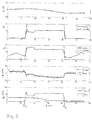
- the behaviour of the system over time t is represented in Fig. 3 in three diagrams.
- the lower curve in Fig. 3 shows the outlet flow q p over time t.
- the middle curve shows the inlet flow q in over time t and the upper curve shows the height h of the fluid level in the pump sump 2 over time t. It can be seen that the inlet flow q in is constant.
- the pump 8 is switched on at the point in time T 1 and is switched off again at the point in time T 3 .
- the level h rises up to the point in time T 1 due to the constant inlet flow q in .
- the inlet flow q in in this time interval is proportional to the increase of the level h.
- the level h drops again on switching on the pump 8 at the point in time T 1 , wherein, as is represented in the equations in Fig. 3 , the change of the level h over time t is proportional to the difference of the inlet flow q in and the outlet flow q p . If the inlet flow q in is constant, as is represented in Fig, 3 , then the outlet flow q p can be determined from the difference of the level change in the case of a switched-on and switched-off pump 8, without further ado. This is no longer possible of the inlet flow q in changes, as is represented in Fig. 4 .
- the three curves in Fig. 4 correspond to the curves in Fig. 3 .
- the inlet flow q in is not constant in the operating condition according to Fig. 4 , but increases at the point in time To and reduces at the point in time T 2 , as is represented in Fig. 4 .
- the speed at which the level h in the pump sump 2 rises increases with the increase of the inlet flow q in at the point in time T 0 in the interval ⁇ t 4 .
- the speed of the dropping of the level h is lower in the time intervals ⁇ t 5 , ⁇ t 6 and ⁇ t 7 between the points in time T 1 and T 2 , than in the comparable interval in the operating condition according to Fig. 3 .
- the speed at which the level h in the pump sump 2 drops increases again in the interval ⁇ t 8 , with the reduction of the inlet flow q in at the point in time T 2 . It is to be recognised that one cannot deduce the outlet flow q p solely from the speed at which the level h changes, if the inlet flow q in changes, since the temporal change of the level h is always proportional to the difference between the inlet flow q in and the outlet flow q p .
- the system model 20 is applied in the manner described hereinafter, in order to be able to determine the outlet flow q p also in such operating conditions.
- the system model 20 consists of the two sub-models 22 and 24. What is essential to the system is the fact that the sub-models 22 and 24 are of a different nature.
- the sub-model 22 describes the inflow behaviour, i.e. the inflow q in
- the sub-model 24 describes or represents the outflow behaviour in the form of the outlet flow q p .
- h corresponds to the level of the fluid level in the pump sump 2, t to the time, ⁇ t a time interval and A(h) to the cross-sectional area of the pump sump 2, wherein the cross-sectional area can be a function of the height h, if the pump sump 2 does not have a cross section which is constant over the height.
- the cross-sectional area A(h) of the pump sump 2 is assumed as being known in the subsequent consideration.
- the two sub-models 22 and 24, apart from the different input variables, comprise different model parameters or parameters ⁇ 0 , ⁇ 1 , ⁇ 2 , ⁇ 3 and ⁇ 0 , ⁇ 1 , ⁇ 2 respectively, which are defined by the parameter evaluation device 30.
- Such a sub-model 24 representing the outflow behaviour or the behaviour of the pump 8 has the advantage that no electrical variable of the pump 8 needs to be detected,
- this model is merely based on the model parameters ⁇ 0 and ⁇ 1 , the switch signal s, the differential pressure ⁇ p between the pressure sensors 10 and 12, as well as time t.
- This version is preferably used if the pump is controlled by a frequency converter as the speed information can be received from the frequency converter.
- the variable s would not be a pure start/stop signal representing the switching-on and switching-off of the pump, but a signal which simultaneously represents how many pumps 8 are simultaneously switched on.
- the electrical power P would represent the average power of one pump, i. e. the sum of the power from all active pumps divided with the number of active pumps.
- the parameters ⁇ and ⁇ of the sub-models 22 and 24 on operation of the pump system are continuously determined and adapted, by the parameter evaluation device 30 on the basis of the previously measured data stored in the data memory 28.
- the thus adapted parameters 32 ( ⁇ , ⁇ ) then form the basis for determining or identifying the inlet flow q in and the outlet flow q p .
- a continuously running adaptation or optimisation of the models is thus effected, so that these sub-models 24 and 24 simulate or represent the system as exactly as possible.
- the manner of functioning of the models is explained further by way of Fig. 5 .
- the upper curve in Fig. 5 shows the change of the height h over time t.
- the second curve shows the electrical power consumption P of the drive motor 14 over time t, and the switch signal s which represents the switched-on condition of the drive motor 14.
- the third curve in Fig. 5 shows the pressure signal which results therefrom, for the differential pressure ⁇ p between the two pressure sensors 10 and 12. The pressure difference ⁇ p increases on switching on the pump 8.
- the fourth curve in Fig. 5 parallel to this shows the pump sump flow q pit , i.e. the flow q pit which leads to the rising and dropping of the level h in the pump sump 2.
- the pump sump flow q pit is the difference between the inlet flow q in and the outlet flow q p .
- the actual pump sump flow q pit which results from the measurement of the height h and the known cross section A(h) of the pump sump 2 is represented in the fourth curve in Fig. 5 as an unbroken line.
- the dashed line shows the estimated pump sump flow q pit,est which is determined on the basis of the sub-models 22 and 24.
- the pump sump flow q pit,est which is thus determined by the models is based on the inlet flow q in,est and the outlet flow q p,est which are determined by the sub-models 22 and 24 and are represented in the lower curve in Fig. 5 .
- the models represent the actually measured pump sump flow q pit in an accurate manner.
- the deduction of the parameters ⁇ and ⁇ for the sub-models 22 and 24 can be effected by way of comparing the result variables determined by the models, with actually measured, corresponding variables, for example whilst using the least-mean-squares method.
- the pump sump flow q pit can be computed in dependence on the time t according to the previous equation from the level h which is measured in the pump sump 2, i.e. this variable can actually be measured and compared to the pump sump flow q pit,est which is determined on the basis of the models.
- the pump sump flow q pit,est which is determined on the basis of the models, it is the case of an estimated pump sump flow which results from the sub-models 22 and 24 which are described above.
- a method which minimises the prediction errors is applied.
- the model parameters ⁇ 0 , ⁇ 1 , ⁇ 2 , ⁇ 3 as well as ⁇ 1 and ⁇ 2 are accordingly adapted for this.
- the aim of the flow evaluation device 18, with the embodiment example according to Fig. 1 is to determine the outlet flow q p .
- the second sub-model 24 is necessary for this.
- the first sub-model 22 representing the inlet flow q in is necessary, in order in the described manner to determine the model parameters ⁇ and ⁇ by way of comparing the estimated pump sump flow q pit,est with the measured pump sump flow q pit .
- the sub-model 22 in this case thus forms an auxiliary model which is used for parameter evaluation.
- Fig. 6 shows a second embodiment example of the invention.
- the embodiment example shows a pump system for the water supply.
- a tank 2' is provided here as a fluid container, wherein the pump 8' is arranged in its inlet 4'.
- the tank 2' lies above the pump 8', so that this pump pumps water or fluid into the tank 2' in an inlet flow q p .
- the fluid can escape out of the tank 2' via the outlet 6' on account of gravity.
- An outlet flow q out is therefore formed.
- a level sensor 34 which for example can likewise be designed as a pressure sensor, as is described by way of Figure 1 , is provided for determining the fluid level or height h in the tank 2'.
- a pressure sensor 36 which detects the outlet pressure p p of the pump 8' is arranged here at the exit side of the pump 8'.
- a first sub-model 22 which represents the inlet flow, in this case the pump flow q p and a second sub-model 24 which represents the outlet flow q out can also be applied in the corresponding manner in the control device for determining the flow.
- the flow in the tank q pit is dependent on the difference of the flows q p and q out .
- the parameter evaluation of the parameters ⁇ and ⁇ for both sub-models 22 and 24 can be effected in a manner which corresponds to that which was previously described.
- the pump flow q p which corresponds to the inlet flow, as in the first embodiment example, can be approximated as a function g ( ⁇ , s, P, ⁇ p).
- ⁇ p is the differential pressure across the pump 8' and the switching variable s represents the number of active pumps in the case that several pumps are arranged in parallel, as has been described beforehand.
- the differential pressure can be calculated as a delivered pump pressure when the pump is operating subtracted from a system pressure, where the system pressure is evaluated and stored when the pump is stopped e. g. both the delivered pump pressure and the system pressure can be measured with one pressure sensor p p 36.
- Fig. 7 shows the course of the height h over time and accordingly the change of the outlet flow q out and of the pump flow q p , wherein the pump 8' is switched on at the point in time T 1 and is switched off at the point in time T 3 .
- a continuous adaptation of the sub-models 22 and 24 can be simultaneously effected with the flow evaluation also with the second embodiment example according to Fig. 6 and 7 .
Abstract
Description
- The invention relates to a pump system as well as to a method for determining the flow in a pump system.
- Pump systems which comprise a fluid container for storing the fluid to be pumped out or the pumped in fluid are known. The fluid level fluctuates in such fluid containers. It is difficult to determine the actual throughflow or exit flow for this reason, since the delivery flow of the pump does not always correspond the throughflow.
-
GB 2 221 073 -
EP 2 258 949 - It is the object of the invention, to improve a pump system with at least one fluid container, to the extent that the flow through the fluid container, i.e. the inlet flow and the exit flow can be determined in a precise manner.
- This object is achieved by a pump system with the features specified in
claim 1, as well as by a pump flow evaluation method with the features specified in claim 15. Preferred embodiments are to be deduced from the associated dependent claims, the subsequent description, as well as the attached figures. - The pump system according to the invention comprises at least one fluid container with an inlet and with an outlet. The fluid to be delivered flows through the inlet into the fluid container and out of this again through the outlet. Moreover, the pump system comprises at least one pump which can be arranged in the inlet or the outlet. This means that the fluid container can be arranged upstream or downstream of the pump in the flow direction. In waste-water systems for example, it is known for the waste-water to be delivered to firstly flow into a pump sump representing the fluid container, and being delivered out of this with the help of the pump, out of the outlet. In contrast, in water supply systems, it is known for example for the pump to deliver the water into a fluid container which is situated at a higher level. This means that the pump delivers the fluid through the inlet into the fluid container. The fluid can flow away out of the fluid container again, due to gravity for example. With both embodiment variants, it is alternatively and/or additionally possible to arrange several fluid containers with associated pumps in series, so that the fluid is always delivered out of a first fluid container into a subsequent, second fluid container. This can be applied in order to be able to bridge larger delivery heads.
- The pump system according to the invention moreover comprises a control device having a flow evaluation device designed to determine or identify the parameters of a flow model describing the flow through the container of the pump system, i.e. the inlet and the exit flow, and to do continuously flow estimation based on the identified parameters of the flow model.
- According to the invention, one envisages determining or estimating the flow with the help of the flow evaluation device. The flow evaluation device for this, according to the invention, is designed in a manner such that a system model is applied for determining the parameters of the flow model. Thereby, what is essential to the invention is that the system model which simulates the complete pump system with the fluid container consists of at least two sub-models. A first of the sub-models describes the inflow behaviour of the container and a second sub-model describes the outflow behaviour of the container, i.e. the outward flow through the outlet. The exit-side flow or exit flow can be determined or estimated via the second sub-model. The sub-models are designed such that they can determine or output the desired flow values continuously on the basis of previously determined model parameters and input variables measured in the system.
- The application of two such sub-models has the advantage that a flow evaluation, which is to say a flow model identification, for the exit flow is also possible even if the flow in the inlet is not constant, since the inflow behaviour is also simulated in a sub-model. In the reverse case too, when the pump delivers fluid into the fluid container, an outflow out of the fluid container and which is not constant in this case can also be simulated by a suitable sub-model by way of the two sub-models. This means that the inflow behaviour and also the outflow behaviour are always taken into account in the system model applied according to the invention, so that fluctuations in the inflow and in the outflow have no influence or only a lesser influence on determining the flow model parameters.
- The two different sub-models are preferably of a different or varying nature. This means that they are preferably independent of one another and have a different behaviour as a reaction to the input parameters. Thus for example the one sub-model is not in the position of assuming the behaviour of the other sub-model or being dependent on the behaviour of the second sub-model. An independent description of the inflow behaviour and of the outflow behaviour out of the container can be achieved in this manner.
- Further preferably, the control device comprises memory means, which are designed to store measurement values (readings) or data, which are/is detected in the pump system. The control device moreover preferably comprises a parameter evaluation device which is designed to determine parameters or model parameters of the at least two sub-models on the basis of the stored data. This means that the models are adapted on the basis of the measured and stored data by way of determining their parameters, so that they describe the system or part-system as accurately as possible.
- The parameter evaluation device is preferably designed in a manner such that the parameters of the first sub-model and the parameters of the second sub-model can be simultaneously determined. Further preferably, the parameter evaluation by way of the parameter evaluation device can be effected simultaneously with the flow estimation in the flow evaluation device. This means that the control device permits a continuous evaluation of the flow with a simultaneous continuous adaptation or optimisation of the sub-models, on the basis of which the flow model parameter evaluation (identification) is effected. The parameter evaluation device determines the model parameters on a cyclic base, e.g. a set of data is collected and used for determining a new set of model parameters. The flow evaluation device uses a former set of model parameter for continuously estimating the flow, when a new set of data is collected, the parameter evaluation device determines a new set of model parameters, The parameter evaluation device is designed such that the parameters for both part models are always evaluated, even if later only one of the sub-models is used for determining the flow. Thus the sub-model which describes the outflow behaviour is preferably used for determining the flow. The other sub-model then serves as an auxiliary model which merely serves for the parameter evaluation of both sub-models.
- The parameter evaluation device is further preferably designed such that the parameters of the at least two sub-models are determined by error minimisation between an estimated output variable which is determined by the sub-models, and a corresponding output variable which has been measured or calculated from measurements done in the system. This in particular can be effected by way of applying the least-mean-squares method. This means that the estimated output variable which is determined by the models is compared to actual output variable, and the parameters of the sub-models are adapted such that the estimated variable differs as little as possible from the actual output variable. The sub-models are therefore adapted such that they describe the system as optimally as possible.
- The described error minimisation can be effected simultaneously for both sub-models, for example by way of a sum or a difference of the two sub-models being formed and being compared to an actual output variable. The actual output variable can thereby correspond to the fluid level or the height of the fluid in the fluid container or its change over time. The change must thereby correspond to the difference between the inflow and the outflow out of the fluid container, and this can be determined from the two sub-models.
- According to a preferred embodiment of the invention, the fluid container is provided with a level sensor which detects the fluid level in the inside of the container, wherein the detected fluid level is stored as part of the acquired data, i.e. is stored in the previously described memory means. The stored fluid level, i.e. in particular the temporal course of the fluid level can then serve as a basis for determining the parameters of the sub-models, in the parameter evaluation device. The level or fluid level can thereby be determined in a direct or indirect manner, for example by way of a pressure sensor which determines the hydrostatic pressure.
- According to a further preferred embodiment, the at least one pump comprises an electrical drive motor and a power detection device, which detects the current (prevailing) electrical power of the drive motor, wherein the electric power is stored as part of the detected data, i.e. is stored in the previously described memory means. This permits the parameter evaluation device to be able to access the stored power values, in order to determine the parameters of the sub-models. The detected electrical power over time is thus preferably stored in the memory means, since the power detection is preferably detected in a continuous manner.
- A pressure sensor is further preferably arranged at the outlet side of the pump and detects the outlet pressure of the pump, wherein the outlet pressure is stored as part of the acquired data, i.e. is stored in the previously described memory means. The parameter evaluation device can thus fall back on stored pressure values, in order to determine the parameters of the sub-models. The pressure sensor preferably detects the pressure in a continuous manner and a temporal course of the outlet pressure is stored in the memory means.
- According to a further preferred embodiment, the control device is designed in a manner such that it detects the number of active pumps in the pump system and/or the rotation speed of the at least one pump, wherein preferably the number of active pumps and/or the rotation speed is stored as a part of the acquired, which is to say detected data, i.e. is stored in the previously described memory means or the described memory device. The parameter evaluation device can thus fall back on the number of active pumps or the rotation speed, in order to determine the parameters of the sub-models. Here too, a temporal course of the number of active pumps and/or of the rotation speed can preferably be stored in the memory means or the memory device.
- According to a preferred embodiment of the invention, the first sub-model is a function of time and of at least one determined model parameter. The model parameter is determined in the described manner by way of the parameter evaluation device.
- The second sub-model is preferably a function of a data which is detected in the system, e.g. of the data to be stored and of at least one determined model parameter. Thereby, it is the case of model parameters which are determined by the previously described parameter evaluation device which is to say are preferably continuously adapted. With regard to the data, it can be the case for example of the output variable corresponding to the fluid level, the electrical power of the drive motor, the exit pressure of the pump, the number of active pumps in the pump system and/or the rotation speed of one or more pumps, as previously described. If the first sub-model is a function of time and the second sub-model is a function of the measured data, then the outputs estimated by these two sub-models are different with regard to their nature and independent of one another, as has been described above as a preferred design.
- The control device is further preferably designed such that the second sub-model is applied in order to determine the pump flow or the flow through the fluid container. The second part model, as described above, is the part model which preferably describes the outflow behaviour of the container. This is particularly the case if the pump is arranged in the outlet of the fluid container. In this case, the first sub-model preferably describes the inflow behaviour into the fluid container. If conversely, the pump is arranged in the inlet or intake of the fluid container, then the second sub-model which describes the pump flow describes or represents the inflow behaviour into the fluid container, whereas the first sub-model describes or represents the outflow behaviour. In the case in which the pump is arranged in the inlet of the fluid container, the flow through the fluid container preferably represents the flow in the outlet of the fluid container, so that in this case the first sub-model can then be used for determining the flow through the fluid container. The control device is accordingly adapted in these cases.
- According to a first preferred embodiment of the invention, the fluid container is a pump sump and the pump is arranged in an outlet, in order to pump fluid out of the pump sump, wherein the first sub-model describes the inflow into the pump sump and the second sub-model the behaviour of the pump, i.e. the outflow behaviour of the fluid container. With regard to the pump, it can preferably be the case of submersible pump, which is immersed into the pump sump. With this design, as described beforehand, the second sub-model is preferably used in order to determine the flow or the hydraulic delivery flow of the pump via the model. The continuous calibration of the sub-models by way of adapting their parameters by way of the parameter evaluation device is advantageous with such a pump system, since with waste-water pumps for example, the efficiency of the pump can rapidly change over time due to contamination and wear. The flow evaluation device according to the invention has the advantage that it continuously calibrates itself, wherein fluctuating inlet flows are also taken into account via the first sub-model.
- According to an alternative embodiment, the pump can be arranged in the inlet, in order to fill the container, wherein the first sub-model describes the outflow out of the container and the second sub-model describes the behaviour of the pump, i.e. the inflow behaviour. With such an embodiment, the first sub-model can be used to determine the exit flow or the flow through the fluid container. Such an arrangement for example can be applied with the supply of water, with which water is pumped via the pump into a fluid container which is situated at a higher location, from which it can flow out again solely on account of gravity. In such a system too, a change of the system characteristics due to wear or contamination can be taken into account by way of continuous calibration or adaptation of the parameters of the sub-models.
- The subject-matter of the invention, apart from the previously described pump system, is a pump flow evaluation method, which can be applied for example in the previously described pump system. The pump flow evaluation method serves for determining the flow which is to say the outlet flow of a pump system, wherein the pump system comprises at least one pump and a fluid container. The pump system can preferably correspond to the pump system according to the preceding description. The method is characterised in that the outlet flow is determined by a system model which consists of at least two sub-models, a sub-model which describes the inflow behaviour of the fluid container and a sub-model which describes the outflow behaviour or the outlet flow of the fluid container. The evaluation of the flow is thereby effected in a manner as has been described beforehand by way of the pump system. The features which are described by way of the pump system thereby likewise represent preferred features of the pump flow evaluation method according to the invention. The preceding description is referred to inasmuch as this is concerned.
- The pump flow evaluation method in the system model preferably applies as least two sub-models which are of a different nature to the extent that they have a different behaviour as a reaction to a change of input values. Thus the two sub-models, as has been described above by way of the pump system, do not influence one another, and it is possible to continuously adapt the parameters of the system model in a manner such that the system model describes the inflow behaviour as well as the outflow behaviour out of the fluid container. When the model parameters have been identified the second sub-model is used continuously for a flow estimation. e.g.
- The invention is hereinafter described by way of example and by way of the attached figures. In these are shown in:
- Fig. 1:
- schematically, a pump system according to the invention, in the form of a pump sump with a pump which is arranged therein,
- Fig. 2:
- schematically, a flow evaluation device according to the in-vention,
- Fig. 3:
- the course of the fluid level in dependence on the inlet flow and outlet flow in the pump sump according to
Fig. 1 , - Fig. 4
- a representation according to
Fig. 3 , but with a fluctuating inlet flow, - Fig. 5
- in several diagrams, the evaluation of the inlet flow and of the pump flow on the basis of a system model,
- Fig. 6
- schematically, a pump system which is suitable for the supply of water, and
- Fig. 7
- diagrams which represent the fluid level in the fluid container according to
Fig. 6 , in dependence on the inflow and the out-flow. - According to a first possible embodiment of the invention, the pump system according to the invention can be designed as a system for delivering waste water.
Fig. 1 shows a corresponding arrangement. Apump sump 2 forms a fluid container, which is provided with aninlet 4 and with anoutlet 6. Theinlet 4 is situated on the upper side and theoutlet 6 on the lower side of thepump sump 2. A pump 8 which delivers water or liquid out of thepump sump 2 is arranged on theoutlet 6. In this example, the pump 8 is arranged outside thepump sump 2. A submersible pump however could also be applied. There are several relevant variables in such a pump system, specifically the inlet flow qin and the outlet flow qp, wherein the outlet flow qp corresponds to the delivery flow of the pump 8. Twopressure sensors first pressure sensor 10 forms a level sensor. Thepressure sensor 10 is arranged in the inside of thepump sump 2, for detecting the hydrostatic pressure at the base of thepump stump 2. The level h of the fluid in the inside of thepump sump 2 can be determined from the hydrostatic pressure in the known manner. Thepressure sensor 12 is arranged in theoutlet 6 or the outlet conduit downstream of the pump 8, i.e. on the delivery side of the pump 8 and detects the outlet pressure pout of the pump 8. A further variable which is relevant to the system is the electrical power consumption P of theelectrical drive motor 14 of the pump 8. The pump 8 preferably comprises n integratedcontrol device 16 which receives sensor signals from thepressure sensors drive motor 14. Thecontrol device 16 can additionally control theelectric drive motor 14 of the pump 8. Thecontrol device 16 moreover comprises a flow evaluation device and by way of this is in the position of determining the flows qin and qp. Alternatively thiscontrol device 16 can be an external device especially if there are two or more pumps in the system. - This
flow evaluation device 18 is represented schematically inFig. 2 . The flow evaluation device uses asystem model 20 simulating the pump system, for the computation or for the approximate evaluation of the flows qp and qin. Thesystem model 20 consists of twosub-models flow evaluation device 18 further comprises adata acquisition module 26 which continuously acquires or detects measured system parameters, in this example the height h of the fluid level in thepump sump 2 which is computed on the basis of the signal of thepressure sensor 10 in thecontrol device 16, the differential pressure Δp across the pump 8, i.e. the pressure difference between thepressure sensors electrical drive motor 14 is switched on or off. This data which is continuously detected by thedata acquisition module 26 is continuously stored in a memory means in the form of adata memory 28. Thereby, the newer data can regularly overwrite older data. Aparameter evaluation device 30 which is likewise part of the flow evaluation device, in the manner described below determines the model parameters orparameters 32 for the sub-models 22 and 24, on the basis of the data stored in thedata memory 28. On the basis of thesub-models 22and 24 formed in such a manner, these determine the flows qp and qin on the basis of supplied, current data measured in the system. - The use of the
system model 20 for determining the flow through the pump system which corresponds to the outlet flow qp of the pump 8, avoids having to measure the flow in a direct manner. The efficiency of the pump changes relatively rapidly since the pump 8 is subjected to a wear and a contamination, so that a flow evaluation is not possible based solely on the electrical variables of thedrive motor 14 and the measured pressures. A change of the level h over time t is also not a reliable variable for the outlet flow qp, if the inlet flow qin simultaneously changes. This is explained by way ofFig. 3 and4 . - The behaviour of the system over time t is represented in
Fig. 3 in three diagrams. The lower curve inFig. 3 shows the outlet flow qp over time t. The middle curve shows the inlet flow qin over time t and the upper curve shows the height h of the fluid level in thepump sump 2 over time t. It can be seen that the inlet flow qin is constant. The pump 8 is switched on at the point in time T1 and is switched off again at the point in time T3. The level h rises up to the point in time T1 due to the constant inlet flow qin. The inlet flow qin in this time interval is proportional to the increase of the level h. The level h drops again on switching on the pump 8 at the point in time T1, wherein, as is represented in the equations inFig. 3 , the change of the level h over time t is proportional to the difference of the inlet flow qin and the outlet flow qp. If the inlet flow qin is constant, as is represented inFig, 3 , then the outlet flow qp can be determined from the difference of the level change in the case of a switched-on and switched-off pump 8, without further ado. This is no longer possible of the inlet flow qin changes, as is represented inFig. 4 . - The three curves in
Fig. 4 correspond to the curves inFig. 3 . In contrast toFig. 3 , the inlet flow qin is not constant in the operating condition according toFig. 4 , but increases at the point in time To and reduces at the point in time T2, as is represented inFig. 4 . As can be recognised in the upper curve, the speed at which the level h in thepump sump 2 rises, increases with the increase of the inlet flow qin at the point in time T0 in the interval Δt4. Accordingly, the speed of the dropping of the level h is lower in the time intervals Δt5, Δt6 and Δt7 between the points in time T1 and T2, than in the comparable interval in the operating condition according toFig. 3 . The speed at which the level h in thepump sump 2 drops, increases again in the interval Δt8, with the reduction of the inlet flow qin at the point in time T2. It is to be recognised that one cannot deduce the outlet flow qp solely from the speed at which the level h changes, if the inlet flow qin changes, since the temporal change of the level h is always proportional to the difference between the inlet flow qin and the outlet flow qp. - The
system model 20 is applied in the manner described hereinafter, in order to be able to determine the outlet flow qp also in such operating conditions. Thesystem model 20 consists of the two sub-models 22 and 24. What is essential to the system is the fact that the sub-models 22 and 24 are of a different nature. The sub-model 22 describes the inflow behaviour, i.e. the inflow qin, whereas the sub-model 24 describes or represents the outflow behaviour in the form of the outlet flow qp. Thefirst model 22 is thereby dependent on a parameter θ and time t, i.e. qin = f (θ t). Thesecond sub-model 24 is of a different nature and is dependent on a parameter λ, the switch-on signal s, the electrical power P and the differential pressure Δp between thepressure sensors - The following equation results due to the fact that the inlet flow qin and the outlet flow qp, as represented by way of
Fig. 3 and4 , are dependent on the change of the height h in the pump sump 2:
- In this formula, h corresponds to the level of the fluid level in the
pump sump 2, t to the time, δt a time interval and A(h) to the cross-sectional area of thepump sump 2, wherein the cross-sectional area can be a function of the height h, if thepump sump 2 does not have a cross section which is constant over the height. The cross-sectional area A(h) of thepump sump 2 is assumed as being known in the subsequent consideration. - The following model can be applied as a first sub-model 22 representing the feed or inflow behaviour:

- The following model can be applied for example as a second sub-model 24 which represents the outflow behaviour:

- The two sub-models 22 and 24, apart from the different input variables, comprise different model parameters or parameters θ0, θ1, θ2, θ3 and λ0, λ1, λ2 respectively, which are defined by the
parameter evaluation device 30. - It is to be understood that the previously mentioned models are only examples. Differently formed models which are different with regard to their nature can also be applied as a sub-model 22 as well as
sub-model 24. Thus for example the sub-model 24 which represents the outflow behaviour can also be simplified:
- Such a model representing the pump 8 is advantageous for example, since the outlet pressure pout is not necessary as an input variable for this. Such a pressure detection is not common in many waste-water installations. Inasmuch as this is concerned, the design of the installation is simplified here. Another simplification of the model could be as follows:

- Such a sub-model 24 representing the outflow behaviour or the behaviour of the pump 8 has the advantage that no electrical variable of the pump 8 needs to be detected, In contrast, this model is merely based on the model parameters λ0 and λ1, the switch signal s, the differential pressure Δp between the
pressure sensors - A more extended version of the sub-model 24 with speed information is:

- This version is preferably used if the pump is controlled by a frequency converter as the speed information can be received from the frequency converter.
- In a case in which more than one pump is to be arranged in a
pump sump 2, which often occurs, there are two different approaches to accordingly represent this by models. On the one hand it is possible to form a model in each case for each pump and to take into account a switch-on, which is to say start/stop signal s for each of the two pumps 8. Two second sub-models 24 would then result in such a case, for example in the form:
- On the other hand, it is possible to use a model or sub-model which simulates both pumps, if both pumps or several pumps 8 are simultaneously switched-on, inasmuch as it is the case of pumps 8 of the same type. In this case, the variable s would not be a pure start/stop signal representing the switching-on and switching-off of the pump, but a signal which simultaneously represents how many pumps 8 are simultaneously switched on. In this case the electrical power P would represent the average power of one pump, i. e. the sum of the power from all active pumps divided with the number of active pumps.
- The parameters λ and θ of the sub-models 22 and 24 on operation of the pump system are continuously determined and adapted, by the
parameter evaluation device 30 on the basis of the previously measured data stored in thedata memory 28. The thus adapted parameters 32 (λ, θ) then form the basis for determining or identifying the inlet flow qin and the outlet flow qp. A continuously running adaptation or optimisation of the models is thus effected, so that these sub-models 24 and 24 simulate or represent the system as exactly as possible. - The manner of functioning of the models is explained further by way of
Fig. 5 . The upper curve inFig. 5 shows the change of the height h over time t. The second curve shows the electrical power consumption P of thedrive motor 14 over time t, and the switch signal s which represents the switched-on condition of thedrive motor 14. One can recognise that the pump 8 is switched on between the point in time T1 at about 13 seconds and the point in time T3 at about 42 seconds. The third curve inFig. 5 shows the pressure signal which results therefrom, for the differential pressure Δp between the twopressure sensors - The fourth curve in
Fig. 5 parallel to this shows the pump sump flow qpit, i.e. the flow qpit which leads to the rising and dropping of the level h in thepump sump 2. The pump sump flow qpit is the difference between the inlet flow qin and the outlet flow qp. The actual pump sump flow qpit which results from the measurement of the height h and the known cross section A(h) of thepump sump 2 is represented in the fourth curve inFig. 5 as an unbroken line. The dashed line shows the estimated pump sump flow qpit,est which is determined on the basis of the sub-models 22 and 24. - The pump sump flow qpit,est which is thus determined by the models is based on the inlet flow qin,est and the outlet flow qp,est which are determined by the sub-models 22 and 24 and are represented in the lower curve in
Fig. 5 . One can recognise that the models represent the actually measured pump sump flow qpit in an accurate manner. - The pump sump flow qpit results according to the following equation:

- The variables used in the equation correspond to the variables which are described above.
- The deduction of the parameters λ and θ for the sub-models 22 and 24 can be effected by way of comparing the result variables determined by the models, with actually measured, corresponding variables, for example whilst using the least-mean-squares method. As explained above, the pump sump flow qpit can be computed in dependence on the time t according to the previous equation from the level h which is measured in the
pump sump 2, i.e. this variable can actually be measured and compared to the pump sump flow qpit,est which is determined on the basis of the models. With regard to the pump sump flow qpit,est which is determined on the basis of the models, it is the case of an estimated pump sump flow which results from the sub-models 22 and 24 which are described above. A method which minimises the prediction errors is applied. The model parameters θ0, θ1, θ2, θ3 as well as λ1 and λ2 are accordingly adapted for this. - The aim of the
flow evaluation device 18, with the embodiment example according toFig. 1 is to determine the outlet flow qp. Actually, only thesecond sub-model 24 is necessary for this. However, in order to be able to determine its parameter λ, the first sub-model 22 representing the inlet flow qin is necessary, in order in the described manner to determine the model parameters λ and θ by way of comparing the estimated pump sump flow qpit,est with the measured pump sump flow qpit. The sub-model 22 in this case thus forms an auxiliary model which is used for parameter evaluation. -
Fig. 6 shows a second embodiment example of the invention. The embodiment example shows a pump system for the water supply. A tank 2' is provided here as a fluid container, wherein the pump 8' is arranged in its inlet 4'. The tank 2' lies above the pump 8', so that this pump pumps water or fluid into the tank 2' in an inlet flow qp. The fluid can escape out of the tank 2' via the outlet 6' on account of gravity. An outlet flow qout is therefore formed. Alevel sensor 34 which for example can likewise be designed as a pressure sensor, as is described by way ofFigure 1 , is provided for determining the fluid level or height h in the tank 2'. A pressure sensor 36 which detects the outlet pressure pp of the pump 8' is arranged here at the exit side of the pump 8'. In this case too, a first sub-model 22 which represents the inlet flow, in this case the pump flow qp and a second sub-model 24 which represents the outlet flow qout can also be applied in the corresponding manner in the control device for determining the flow. Here too, the flow in the tank qpit is dependent on the difference of the flows qp and qout. Inasmuch as this is concerned, the parameter evaluation of the parameters λ and θ for both sub-models 22 and 24 can be effected in a manner which corresponds to that which was previously described. - A Fourier series for example can be applied as a model for the outlet flow qout


- The pump flow qp which corresponds to the inlet flow, as in the first embodiment example, can be approximated as a function g (λ, s, P, Δp). Thereby, Δp is the differential pressure across the pump 8' and the switching variable s represents the number of active pumps in the case that several pumps are arranged in parallel, as has been described beforehand.
- The differential pressure can be calculated as a delivered pump pressure when the pump is operating subtracted from a system pressure, where the system pressure is evaluated and stored when the pump is stopped e. g. both the delivered pump pressure and the system pressure can be measured with one pressure sensor pp 36.
-
Fig. 7 shows the course of the height h over time and accordingly the change of the outlet flow qout and of the pump flow qp, wherein the pump 8' is switched on at the point in time T1 and is switched off at the point in time T3. - As is schematically represented in
Fig. 2 , a continuous adaptation of the sub-models 22 and 24 can be simultaneously effected with the flow evaluation also with the second embodiment example according toFig. 6 and 7 . -
- 2
- pump sump
- 2'
- tank
- 4, 4'
- inlet
- 6, 6'
- outlet
- 8, 8'
- pump
- 10
- pressure sensor, level sensor
- 12
- pressure sensor
- 14
- drive motor
- 16
- control device
- 18
- flow evaluation device
- 20
- system model
- 22, 24
- sub-models
- 26
- data acquisition module
- 28
- data memory, memory means
- 30
- parameter evaluation device
- 32
- parameter
- 34
- level sensor
- 36
- pressure sensor
- qin
- inlet flow of the pump sump
- qout
- outlet flow
- qp
- outlet flow of the pump sump, pump flow
- qpit
- pump sump flow, qpit = qp - qout or qpit = qin - qp
- h
- level
- P
- electric power
- pout
- outlet pressure of the pump
- s
- switch-on signal which represents the number of pumps which are switched on
- Δp
- differential pressure across the pump
- t
- time
- Δt, δt
- time intervals
- E(θ, t)
- mathematic model which describes the inflow be-haviour
- θ
- parameter vector which comprises the parameters of the model for the inflow behaviour
- θi
- parameter
- g (λ, s, P, Δp)
- mathematic model which describes the pump flow or the outflow behaviour
- λ
- parameter vector which contains the parameters of the model describing the pump flow
- λi
- parameter
Claims (16)
- A pump system with at least one fluid container (2; 2') which comprises an inlet (4; 4') and an outlet (6; 6'), with at least one pump (8; 8') which is arranged in the inlet (4) or the outlet (6), and with a control device (16) which comprises a flow evaluation device (18) for determining a flow (9) through the fluid container (2;2') of the pump system,
characterised in that
the flow evaluation device (18) is designed in a manner such that it uses a system model (20) for determining the flow, wherein the system model (20) consists of at least two different sub-models (22, 24), a sub-model (22) which describes the inflow behaviour of the fluid container (2; 2') and a sub-model (24) which describes the outflow behaviour of the fluid container (2; 2'). - A pump system according to claim 1, characterised in that the two different sub-models (22, 24) are of a different nature.
- A pump system according to claim 1 or 2, characterised in that the control device (16) comprises memory means (28) which are designed to store data acquired in the pump system, and a parameter evaluation device (30) which is designed to determine parameters of the at least two sub-models (22, 24) on the basis of the stored data.
- A pump system according to claim 3, characterised in that the parameter evaluation device (30) is designed in a manner such that the parameters of the first sub-model (22) and the parameters of the second sub-model (24) are simultaneously determined.
- A pump system according to claim 3 or 4, characterised in that the parameter evaluation device (30) is designed to determine the parameters of the at least two sub-models (22, 24) by way of error minimisation between an estimated output variable (qpit,est) which is determined by the sub-models (22, 24), and a corresponding output variable (qpit) which has been measured or calculated in the system, in particularly by way of the use of the least-mean-squares method.
- A pump system according to one of the claims 3 to 5, characterised in that the fluid container (2; 2') is provided with a level sensor (10; 34) which detects the fluid level (h) in the inside of the fluid container (2; 2'), wherein the detected fluid level (h) is stored as part of the acquired data.
- A pump system according to one of the claims 3 to 6, characterised in that the at least one pump (8; 8') comprises an electrical drive motor (14) and a power detection device which detects the current electrical power (P) of the drive motor (14), wherein the electric power (P) is stored as part of the acquired data.
- A pump system according to one of the claims 3 to 7, characterised in that a pressure sensor (12; 36) is arranged at the outlet side of the pump (8; 8'), said pressure sensor detecting the outlet pressure (pout) of the pump (8; 8'), wherein the outlet pressure (pout) is stored as part of the acquired data.
- A pump system according to one of the preceding claims, characterised in that the control device (16) is designed in a manner such that it detects the number of active pumps (8; 8') in the pump system and/or the rotation speed of the at least one pump (8; 8'), wherein preferably the number (s) of the active pumps (8; 8') and/or the rotation speed is stored as part of the acquired data.
- A pump system according to one of the preceding claims, characterised in that the first sub-model (22) is a function of time (t) and of at least one determined model parameter (θ).
- A pump system according to one of the preceding claims, characterised in that the second sub-model (24) is a function of data which is acquired in the system, and of at least at least one determined model parameter (λ).
- A pump system according to one of the preceding claims, characterised in that the control device (16) is designed in a manner such that the second sub-model (24) is used in order to determine the pump flow (qp).
- A pump system according to one of the preceding claims, characterised in that the fluid container is a pump sump (2), and the pump (8) is arranged in an outlet (4), in order to pump fluid out of the pump sump (2), wherein the first sub-model (22) describes the inflow into the pump sump (2) and the second sub-model (24) describes the behaviour of the pump (8).
- A pump system according to one of the claims 1 to 12, characterised in that the pump (8') is arranged in the inlet (2'), in order to fill the fluid container (2'), wherein the first sub-model (22) describes the outflow out of the fluid container (2') and the second sub-model (24) describes the behaviour of the pump (8).
- A pump flow evaluation method for determining the outlet flow of a pump system which comprises at least one pump (8) and a fluid container (2), characterised in that the outlet flow is determined by a system model (20) which consists of at least two sub-models (22, 24), of a part model (22) which describes the inflow behaviour of the fluid container (2) and of a sub-model (24) which describes the outflow behaviour of the fluid container (2).
- A pump flow evaluation method according to claim 15, characterised in that the at least two sub-models (22, 24) are of a different nature to the extent that they have a different behaviour as a reaction to a change of input values.
Priority Applications (5)
| Application Number | Priority Date | Filing Date | Title |
|---|---|---|---|
| DK15202953.4T DK3187735T3 (en) | 2015-12-29 | 2015-12-29 | Pump system as well as a method for determining the flow of a pump system |
| EP15202953.4A EP3187735B1 (en) | 2015-12-29 | 2015-12-29 | Pump system as well as a method for determining the flow in a pump system |
| RU2016151717A RU2662268C2 (en) | 2015-12-29 | 2016-12-28 | Pumping system, and also the flow rate in the pumping system determining method |
| US15/392,289 US10480968B2 (en) | 2015-12-29 | 2016-12-28 | Pump system and method for determining the flow in a pump system |
| CN201611240789.3A CN106930959B (en) | 2015-12-29 | 2016-12-29 | Pumping system and method for determining the flow in pumping system |
Applications Claiming Priority (1)
| Application Number | Priority Date | Filing Date | Title |
|---|---|---|---|
| EP15202953.4A EP3187735B1 (en) | 2015-12-29 | 2015-12-29 | Pump system as well as a method for determining the flow in a pump system |
Publications (2)
| Publication Number | Publication Date |
|---|---|
| EP3187735A1 true EP3187735A1 (en) | 2017-07-05 |
| EP3187735B1 EP3187735B1 (en) | 2019-11-06 |
Family
ID=55066439
Family Applications (1)
| Application Number | Title | Priority Date | Filing Date |
|---|---|---|---|
| EP15202953.4A Active EP3187735B1 (en) | 2015-12-29 | 2015-12-29 | Pump system as well as a method for determining the flow in a pump system |
Country Status (5)
| Country | Link |
|---|---|
| US (1) | US10480968B2 (en) |
| EP (1) | EP3187735B1 (en) |
| CN (1) | CN106930959B (en) |
| DK (1) | DK3187735T3 (en) |
| RU (1) | RU2662268C2 (en) |
Cited By (1)
| Publication number | Priority date | Publication date | Assignee | Title |
|---|---|---|---|---|
| EP4198306A1 (en) * | 2021-12-20 | 2023-06-21 | Xylem Europe GmbH | Method for determining the cross-sectional area of a tank of a pump station |
Families Citing this family (9)
| Publication number | Priority date | Publication date | Assignee | Title |
|---|---|---|---|---|
| US10704935B2 (en) | 2016-12-04 | 2020-07-07 | Buoy Labs, Inc. | Fluid flow detector with tethered drag block |
| CN107462290B (en) * | 2017-06-13 | 2020-06-16 | 珠海格力电器股份有限公司 | Water flow statistical method and device |
| USD866375S1 (en) | 2017-08-02 | 2019-11-12 | Buoy Labs, Inc. | Water flow monitoring device |
| US11781895B2 (en) | 2018-02-23 | 2023-10-10 | Buoy Labs, Inc. | Fluid flow analysis and management |
| US10921765B2 (en) | 2017-12-20 | 2021-02-16 | Siemens Aktiengesellschaft | Digital twin of centrifugal pump in pumping systems |
| EP3567256A1 (en) * | 2018-05-11 | 2019-11-13 | Grundfos Holding A/S | A monitoring module and method for identifying an operating scenario in a wastewater pumping station |
| DE102018217439A1 (en) * | 2018-10-11 | 2020-04-16 | Albert Ziegler Gmbh | Pump device |
| EP3916363A1 (en) * | 2020-05-26 | 2021-12-01 | Xylem Europe GmbH | Method for determining a pumped flow from a pump and a flowmeter |
| LU501040B1 (en) * | 2021-12-17 | 2023-06-19 | Wilo Se | Process for determining the flow rate and/or head |
Citations (4)
| Publication number | Priority date | Publication date | Assignee | Title |
|---|---|---|---|---|
| GB2221073A (en) | 1988-06-08 | 1990-01-24 | Sarlin Ab Oy E | Monitoring a pumping station |
| US5831174A (en) * | 1995-06-05 | 1998-11-03 | Beaudoin; Benoit | Pump station flowmeter |
| EP2258949A1 (en) | 2009-06-02 | 2010-12-08 | Grundfos Management A/S | Method for recording characteristic values, in particular values, in particular of parameters of a centrifugal pump powered by an electric motor integrated into an assembly |
| US20140255216A1 (en) * | 2013-03-11 | 2014-09-11 | Grundfos Holding A/S | Pump system |
Family Cites Families (6)
| Publication number | Priority date | Publication date | Assignee | Title |
|---|---|---|---|---|
| SU1366703A1 (en) * | 1985-04-03 | 1988-01-15 | Киевский институт автоматики им.ХХУ съезда КПСС | Method of automatic control for transferring pumping station and device for effecting same |
| DE19931961A1 (en) * | 1999-07-12 | 2001-02-01 | Danfoss As | Method for controlling a delivery quantity of a pump |
| US7600985B2 (en) * | 2004-10-28 | 2009-10-13 | Ingersoll-Rand Company | Pump assembly, suppression apparatus for use with a pump, and method of controlling a pump assembly |
| CN101033748B (en) * | 2006-03-08 | 2013-07-24 | Itt制造企业公司 | Method for determining pump flow without the use of traditional sensors |
| BR112012016806A2 (en) * | 2010-01-11 | 2016-04-19 | Inergy Automotive Systems Res | method for setting a pump of a scr |
| CN103016321A (en) * | 2011-09-20 | 2013-04-03 | 朗德华信(北京)自控技术有限公司 | System and method for managing and controlling water pump based on cloud computing |
-
2015
- 2015-12-29 EP EP15202953.4A patent/EP3187735B1/en active Active
- 2015-12-29 DK DK15202953.4T patent/DK3187735T3/en active
-
2016
- 2016-12-28 RU RU2016151717A patent/RU2662268C2/en active
- 2016-12-28 US US15/392,289 patent/US10480968B2/en active Active
- 2016-12-29 CN CN201611240789.3A patent/CN106930959B/en active Active
Patent Citations (5)
| Publication number | Priority date | Publication date | Assignee | Title |
|---|---|---|---|---|
| GB2221073A (en) | 1988-06-08 | 1990-01-24 | Sarlin Ab Oy E | Monitoring a pumping station |
| US5831174A (en) * | 1995-06-05 | 1998-11-03 | Beaudoin; Benoit | Pump station flowmeter |
| EP2258949A1 (en) | 2009-06-02 | 2010-12-08 | Grundfos Management A/S | Method for recording characteristic values, in particular values, in particular of parameters of a centrifugal pump powered by an electric motor integrated into an assembly |
| US20120136590A1 (en) * | 2009-06-02 | 2012-05-31 | Grundfos Management A/S | Method for determining characteristic values, particularly of parameters, of a centrifugal pump aggregate driven by an electric motor and integrated in a system |
| US20140255216A1 (en) * | 2013-03-11 | 2014-09-11 | Grundfos Holding A/S | Pump system |
Cited By (2)
| Publication number | Priority date | Publication date | Assignee | Title |
|---|---|---|---|---|
| EP4198306A1 (en) * | 2021-12-20 | 2023-06-21 | Xylem Europe GmbH | Method for determining the cross-sectional area of a tank of a pump station |
| WO2023117839A1 (en) * | 2021-12-20 | 2023-06-29 | Xylem Europe Gmbh | Method for determining the cross-sectional area of a tank of a pump station |
Also Published As
| Publication number | Publication date |
|---|---|
| RU2016151717A (en) | 2018-07-02 |
| DK3187735T3 (en) | 2020-02-10 |
| RU2016151717A3 (en) | 2018-07-02 |
| US20170184429A1 (en) | 2017-06-29 |
| CN106930959A (en) | 2017-07-07 |
| US10480968B2 (en) | 2019-11-19 |
| RU2662268C2 (en) | 2018-07-25 |
| CN106930959B (en) | 2019-05-07 |
| EP3187735B1 (en) | 2019-11-06 |
Similar Documents
| Publication | Publication Date | Title |
|---|---|---|
| EP3187735B1 (en) | Pump system as well as a method for determining the flow in a pump system | |
| JP5746155B2 (en) | Method for determining characteristic values, in particular parameters, of an electric motor driven centrifugal pump device incorporated in equipment | |
| EP2270342B1 (en) | Leakage detection system in a wind turbine | |
| US9181954B2 (en) | Method in connection with a pump driven with a frequency converter and frequency converter | |
| EP2088401B1 (en) | A method for determining pump flow rate | |
| EP2746477B1 (en) | Method for operating a wastewater pumping station | |
| EP2721303B1 (en) | Method for controlling at least a part of a pump station | |
| US8740574B2 (en) | Method and apparatus for adjusting a pump drive so that a pump flow corresponds with an incoming flow | |
| US8302463B2 (en) | Loss detection system for open channel networks | |
| JP2007040135A (en) | Variable speed water supply device | |
| US20220268284A1 (en) | Submersible pump system, information processing device, and computer program | |
| WO2016132108A1 (en) | Pump monitoring method | |
| JPWO2021029387A5 (en) | ||
| RU2284394C2 (en) | Water-supply system control method | |
| JP3984006B2 (en) | Inflow liquid amount prediction calculation apparatus and inflow liquid amount prediction calculation method below lower limit liquid level of pump equipment | |
| JP6410293B2 (en) | Sensor calibration system, method, and program | |
| AU2008229735B2 (en) | A method for determining pump flow rate | |
| JP5613520B2 (en) | Pump characteristic measuring method and pump characteristic measuring apparatus | |
| CN117769627A (en) | State monitoring system | |
| CA3011219A1 (en) | A method for determining the viscosity of a conveying fluid conveyed by means of a pump |
Legal Events
| Date | Code | Title | Description |
|---|---|---|---|
| PUAI | Public reference made under article 153(3) epc to a published international application that has entered the european phase |
Free format text: ORIGINAL CODE: 0009012 |
|
| STAA | Information on the status of an ep patent application or granted ep patent |
Free format text: STATUS: THE APPLICATION HAS BEEN PUBLISHED |
|
| AK | Designated contracting states |
Kind code of ref document: A1 Designated state(s): AL AT BE BG CH CY CZ DE DK EE ES FI FR GB GR HR HU IE IS IT LI LT LU LV MC MK MT NL NO PL PT RO RS SE SI SK SM TR |
|
| AX | Request for extension of the european patent |
Extension state: BA ME |
|
| STAA | Information on the status of an ep patent application or granted ep patent |
Free format text: STATUS: REQUEST FOR EXAMINATION WAS MADE |
|
| 17P | Request for examination filed |
Effective date: 20171222 |
|
| RBV | Designated contracting states (corrected) |
Designated state(s): AL AT BE BG CH CY CZ DE DK EE ES FI FR GB GR HR HU IE IS IT LI LT LU LV MC MK MT NL NO PL PT RO RS SE SI SK SM TR |
|
| GRAP | Despatch of communication of intention to grant a patent |
Free format text: ORIGINAL CODE: EPIDOSNIGR1 |
|
| STAA | Information on the status of an ep patent application or granted ep patent |
Free format text: STATUS: GRANT OF PATENT IS INTENDED |
|
| INTG | Intention to grant announced |
Effective date: 20190603 |
|
| GRAS | Grant fee paid |
Free format text: ORIGINAL CODE: EPIDOSNIGR3 |
|
| GRAA | (expected) grant |
Free format text: ORIGINAL CODE: 0009210 |
|
| STAA | Information on the status of an ep patent application or granted ep patent |
Free format text: STATUS: THE PATENT HAS BEEN GRANTED |
|
| AK | Designated contracting states |
Kind code of ref document: B1 Designated state(s): AL AT BE BG CH CY CZ DE DK EE ES FI FR GB GR HR HU IE IS IT LI LT LU LV MC MK MT NL NO PL PT RO RS SE SI SK SM TR |
|
| REG | Reference to a national code |
Ref country code: GB Ref legal event code: FG4D |
|
| REG | Reference to a national code |
Ref country code: CH Ref legal event code: EP Ref country code: AT Ref legal event code: REF Ref document number: 1199061 Country of ref document: AT Kind code of ref document: T Effective date: 20191115 |
|
| REG | Reference to a national code |
Ref country code: IE Ref legal event code: FG4D |
|
| REG | Reference to a national code |
Ref country code: DE Ref legal event code: R096 Ref document number: 602015041059 Country of ref document: DE |
|
| REG | Reference to a national code |
Ref country code: DK Ref legal event code: T3 Effective date: 20200207 |
|
| REG | Reference to a national code |
Ref country code: NL Ref legal event code: MP Effective date: 20191106 |
|
| REG | Reference to a national code |
Ref country code: LT Ref legal event code: MG4D |
|
| PG25 | Lapsed in a contracting state [announced via postgrant information from national office to epo] |
Ref country code: NO Free format text: LAPSE BECAUSE OF FAILURE TO SUBMIT A TRANSLATION OF THE DESCRIPTION OR TO PAY THE FEE WITHIN THE PRESCRIBED TIME-LIMIT Effective date: 20200206 Ref country code: FI Free format text: LAPSE BECAUSE OF FAILURE TO SUBMIT A TRANSLATION OF THE DESCRIPTION OR TO PAY THE FEE WITHIN THE PRESCRIBED TIME-LIMIT Effective date: 20191106 Ref country code: BG Free format text: LAPSE BECAUSE OF FAILURE TO SUBMIT A TRANSLATION OF THE DESCRIPTION OR TO PAY THE FEE WITHIN THE PRESCRIBED TIME-LIMIT Effective date: 20200206 Ref country code: GR Free format text: LAPSE BECAUSE OF FAILURE TO SUBMIT A TRANSLATION OF THE DESCRIPTION OR TO PAY THE FEE WITHIN THE PRESCRIBED TIME-LIMIT Effective date: 20200207 Ref country code: LT Free format text: LAPSE BECAUSE OF FAILURE TO SUBMIT A TRANSLATION OF THE DESCRIPTION OR TO PAY THE FEE WITHIN THE PRESCRIBED TIME-LIMIT Effective date: 20191106 Ref country code: NL Free format text: LAPSE BECAUSE OF FAILURE TO SUBMIT A TRANSLATION OF THE DESCRIPTION OR TO PAY THE FEE WITHIN THE PRESCRIBED TIME-LIMIT Effective date: 20191106 Ref country code: PT Free format text: LAPSE BECAUSE OF FAILURE TO SUBMIT A TRANSLATION OF THE DESCRIPTION OR TO PAY THE FEE WITHIN THE PRESCRIBED TIME-LIMIT Effective date: 20200306 Ref country code: PL Free format text: LAPSE BECAUSE OF FAILURE TO SUBMIT A TRANSLATION OF THE DESCRIPTION OR TO PAY THE FEE WITHIN THE PRESCRIBED TIME-LIMIT Effective date: 20191106 Ref country code: LV Free format text: LAPSE BECAUSE OF FAILURE TO SUBMIT A TRANSLATION OF THE DESCRIPTION OR TO PAY THE FEE WITHIN THE PRESCRIBED TIME-LIMIT Effective date: 20191106 Ref country code: SE Free format text: LAPSE BECAUSE OF FAILURE TO SUBMIT A TRANSLATION OF THE DESCRIPTION OR TO PAY THE FEE WITHIN THE PRESCRIBED TIME-LIMIT Effective date: 20191106 |
|
| PG25 | Lapsed in a contracting state [announced via postgrant information from national office to epo] |
Ref country code: IS Free format text: LAPSE BECAUSE OF FAILURE TO SUBMIT A TRANSLATION OF THE DESCRIPTION OR TO PAY THE FEE WITHIN THE PRESCRIBED TIME-LIMIT Effective date: 20200306 Ref country code: RS Free format text: LAPSE BECAUSE OF FAILURE TO SUBMIT A TRANSLATION OF THE DESCRIPTION OR TO PAY THE FEE WITHIN THE PRESCRIBED TIME-LIMIT Effective date: 20191106 Ref country code: HR Free format text: LAPSE BECAUSE OF FAILURE TO SUBMIT A TRANSLATION OF THE DESCRIPTION OR TO PAY THE FEE WITHIN THE PRESCRIBED TIME-LIMIT Effective date: 20191106 |
|
| PG25 | Lapsed in a contracting state [announced via postgrant information from national office to epo] |
Ref country code: AL Free format text: LAPSE BECAUSE OF FAILURE TO SUBMIT A TRANSLATION OF THE DESCRIPTION OR TO PAY THE FEE WITHIN THE PRESCRIBED TIME-LIMIT Effective date: 20191106 |
|
| PG25 | Lapsed in a contracting state [announced via postgrant information from national office to epo] |
Ref country code: ES Free format text: LAPSE BECAUSE OF FAILURE TO SUBMIT A TRANSLATION OF THE DESCRIPTION OR TO PAY THE FEE WITHIN THE PRESCRIBED TIME-LIMIT Effective date: 20191106 Ref country code: RO Free format text: LAPSE BECAUSE OF FAILURE TO SUBMIT A TRANSLATION OF THE DESCRIPTION OR TO PAY THE FEE WITHIN THE PRESCRIBED TIME-LIMIT Effective date: 20191106 Ref country code: CZ Free format text: LAPSE BECAUSE OF FAILURE TO SUBMIT A TRANSLATION OF THE DESCRIPTION OR TO PAY THE FEE WITHIN THE PRESCRIBED TIME-LIMIT Effective date: 20191106 Ref country code: EE Free format text: LAPSE BECAUSE OF FAILURE TO SUBMIT A TRANSLATION OF THE DESCRIPTION OR TO PAY THE FEE WITHIN THE PRESCRIBED TIME-LIMIT Effective date: 20191106 |
|
| REG | Reference to a national code |
Ref country code: CH Ref legal event code: PL |
|
| REG | Reference to a national code |
Ref country code: DE Ref legal event code: R097 Ref document number: 602015041059 Country of ref document: DE |
|
| REG | Reference to a national code |
Ref country code: AT Ref legal event code: MK05 Ref document number: 1199061 Country of ref document: AT Kind code of ref document: T Effective date: 20191106 |
|
| REG | Reference to a national code |
Ref country code: BE Ref legal event code: MM Effective date: 20191231 |
|
| PG25 | Lapsed in a contracting state [announced via postgrant information from national office to epo] |
Ref country code: MC Free format text: LAPSE BECAUSE OF FAILURE TO SUBMIT A TRANSLATION OF THE DESCRIPTION OR TO PAY THE FEE WITHIN THE PRESCRIBED TIME-LIMIT Effective date: 20191106 Ref country code: SK Free format text: LAPSE BECAUSE OF FAILURE TO SUBMIT A TRANSLATION OF THE DESCRIPTION OR TO PAY THE FEE WITHIN THE PRESCRIBED TIME-LIMIT Effective date: 20191106 Ref country code: SM Free format text: LAPSE BECAUSE OF FAILURE TO SUBMIT A TRANSLATION OF THE DESCRIPTION OR TO PAY THE FEE WITHIN THE PRESCRIBED TIME-LIMIT Effective date: 20191106 |
|
| PLBE | No opposition filed within time limit |
Free format text: ORIGINAL CODE: 0009261 |
|
| STAA | Information on the status of an ep patent application or granted ep patent |
Free format text: STATUS: NO OPPOSITION FILED WITHIN TIME LIMIT |
|
| 26N | No opposition filed |
Effective date: 20200807 |
|
| PG25 | Lapsed in a contracting state [announced via postgrant information from national office to epo] |
Ref country code: IE Free format text: LAPSE BECAUSE OF NON-PAYMENT OF DUE FEES Effective date: 20191229 Ref country code: LU Free format text: LAPSE BECAUSE OF NON-PAYMENT OF DUE FEES Effective date: 20191229 |
|
| PG25 | Lapsed in a contracting state [announced via postgrant information from national office to epo] |
Ref country code: LI Free format text: LAPSE BECAUSE OF NON-PAYMENT OF DUE FEES Effective date: 20191231 Ref country code: AT Free format text: LAPSE BECAUSE OF FAILURE TO SUBMIT A TRANSLATION OF THE DESCRIPTION OR TO PAY THE FEE WITHIN THE PRESCRIBED TIME-LIMIT Effective date: 20191106 Ref country code: CH Free format text: LAPSE BECAUSE OF NON-PAYMENT OF DUE FEES Effective date: 20191231 Ref country code: SI Free format text: LAPSE BECAUSE OF FAILURE TO SUBMIT A TRANSLATION OF THE DESCRIPTION OR TO PAY THE FEE WITHIN THE PRESCRIBED TIME-LIMIT Effective date: 20191106 Ref country code: BE Free format text: LAPSE BECAUSE OF NON-PAYMENT OF DUE FEES Effective date: 20191231 |
|
| PG25 | Lapsed in a contracting state [announced via postgrant information from national office to epo] |
Ref country code: CY Free format text: LAPSE BECAUSE OF FAILURE TO SUBMIT A TRANSLATION OF THE DESCRIPTION OR TO PAY THE FEE WITHIN THE PRESCRIBED TIME-LIMIT Effective date: 20191106 |
|
| PG25 | Lapsed in a contracting state [announced via postgrant information from national office to epo] |
Ref country code: MT Free format text: LAPSE BECAUSE OF FAILURE TO SUBMIT A TRANSLATION OF THE DESCRIPTION OR TO PAY THE FEE WITHIN THE PRESCRIBED TIME-LIMIT Effective date: 20191106 Ref country code: HU Free format text: LAPSE BECAUSE OF FAILURE TO SUBMIT A TRANSLATION OF THE DESCRIPTION OR TO PAY THE FEE WITHIN THE PRESCRIBED TIME-LIMIT; INVALID AB INITIO Effective date: 20151229 |
|
| PG25 | Lapsed in a contracting state [announced via postgrant information from national office to epo] |
Ref country code: TR Free format text: LAPSE BECAUSE OF FAILURE TO SUBMIT A TRANSLATION OF THE DESCRIPTION OR TO PAY THE FEE WITHIN THE PRESCRIBED TIME-LIMIT Effective date: 20191106 |
|
| PG25 | Lapsed in a contracting state [announced via postgrant information from national office to epo] |
Ref country code: MK Free format text: LAPSE BECAUSE OF FAILURE TO SUBMIT A TRANSLATION OF THE DESCRIPTION OR TO PAY THE FEE WITHIN THE PRESCRIBED TIME-LIMIT Effective date: 20191106 |
|
| REG | Reference to a national code |
Ref country code: DE Ref legal event code: R082 Ref document number: 602015041059 Country of ref document: DE |
|
| PGFP | Annual fee paid to national office [announced via postgrant information from national office to epo] |
Ref country code: GB Payment date: 20231220 Year of fee payment: 9 |
|
| PGFP | Annual fee paid to national office [announced via postgrant information from national office to epo] |
Ref country code: IT Payment date: 20231228 Year of fee payment: 9 Ref country code: FR Payment date: 20231221 Year of fee payment: 9 Ref country code: DK Payment date: 20231227 Year of fee payment: 9 Ref country code: DE Payment date: 20231214 Year of fee payment: 9 |