US6149526A - Variable length steering shaft for steering mechanisms of motor vehicles - Google Patents
Variable length steering shaft for steering mechanisms of motor vehicles Download PDFInfo
- Publication number
- US6149526A US6149526A US09/189,089 US18908998A US6149526A US 6149526 A US6149526 A US 6149526A US 18908998 A US18908998 A US 18908998A US 6149526 A US6149526 A US 6149526A
- Authority
- US
- United States
- Prior art keywords
- external
- profile
- slide sleeve
- profile member
- tubular member
- Prior art date
- Legal status (The legal status is an assumption and is not a legal conclusion. Google has not performed a legal analysis and makes no representation as to the accuracy of the status listed.)
- Expired - Lifetime
Links
Images
Classifications
-
- B—PERFORMING OPERATIONS; TRANSPORTING
- B62—LAND VEHICLES FOR TRAVELLING OTHERWISE THAN ON RAILS
- B62D—MOTOR VEHICLES; TRAILERS
- B62D1/00—Steering controls, i.e. means for initiating a change of direction of the vehicle
- B62D1/02—Steering controls, i.e. means for initiating a change of direction of the vehicle vehicle-mounted
- B62D1/16—Steering columns
- B62D1/18—Steering columns yieldable or adjustable, e.g. tiltable
- B62D1/185—Steering columns yieldable or adjustable, e.g. tiltable adjustable by axial displacement, e.g. telescopically
-
- F—MECHANICAL ENGINEERING; LIGHTING; HEATING; WEAPONS; BLASTING
- F16—ENGINEERING ELEMENTS AND UNITS; GENERAL MEASURES FOR PRODUCING AND MAINTAINING EFFECTIVE FUNCTIONING OF MACHINES OR INSTALLATIONS; THERMAL INSULATION IN GENERAL
- F16C—SHAFTS; FLEXIBLE SHAFTS; ELEMENTS OR CRANKSHAFT MECHANISMS; ROTARY BODIES OTHER THAN GEARING ELEMENTS; BEARINGS
- F16C29/00—Bearings for parts moving only linearly
- F16C29/02—Sliding-contact bearings
-
- F—MECHANICAL ENGINEERING; LIGHTING; HEATING; WEAPONS; BLASTING
- F16—ENGINEERING ELEMENTS AND UNITS; GENERAL MEASURES FOR PRODUCING AND MAINTAINING EFFECTIVE FUNCTIONING OF MACHINES OR INSTALLATIONS; THERMAL INSULATION IN GENERAL
- F16C—SHAFTS; FLEXIBLE SHAFTS; ELEMENTS OR CRANKSHAFT MECHANISMS; ROTARY BODIES OTHER THAN GEARING ELEMENTS; BEARINGS
- F16C3/00—Shafts; Axles; Cranks; Eccentrics
- F16C3/02—Shafts; Axles
- F16C3/03—Shafts; Axles telescopic
- F16C3/035—Shafts; Axles telescopic with built-in bearings
-
- F—MECHANICAL ENGINEERING; LIGHTING; HEATING; WEAPONS; BLASTING
- F16—ENGINEERING ELEMENTS AND UNITS; GENERAL MEASURES FOR PRODUCING AND MAINTAINING EFFECTIVE FUNCTIONING OF MACHINES OR INSTALLATIONS; THERMAL INSULATION IN GENERAL
- F16D—COUPLINGS FOR TRANSMITTING ROTATION; CLUTCHES; BRAKES
- F16D3/00—Yielding couplings, i.e. with means permitting movement between the connected parts during the drive
- F16D3/02—Yielding couplings, i.e. with means permitting movement between the connected parts during the drive adapted to specific functions
- F16D3/06—Yielding couplings, i.e. with means permitting movement between the connected parts during the drive adapted to specific functions specially adapted to allow axial displacement
-
- F—MECHANICAL ENGINEERING; LIGHTING; HEATING; WEAPONS; BLASTING
- F16—ENGINEERING ELEMENTS AND UNITS; GENERAL MEASURES FOR PRODUCING AND MAINTAINING EFFECTIVE FUNCTIONING OF MACHINES OR INSTALLATIONS; THERMAL INSULATION IN GENERAL
- F16F—SPRINGS; SHOCK-ABSORBERS; MEANS FOR DAMPING VIBRATION
- F16F15/00—Suppression of vibrations in systems; Means or arrangements for avoiding or reducing out-of-balance forces, e.g. due to motion
- F16F15/10—Suppression of vibrations in rotating systems by making use of members moving with the system
- F16F15/12—Suppression of vibrations in rotating systems by making use of members moving with the system using elastic members or friction-damping members, e.g. between a rotating shaft and a gyratory mass mounted thereon
- F16F15/121—Suppression of vibrations in rotating systems by making use of members moving with the system using elastic members or friction-damping members, e.g. between a rotating shaft and a gyratory mass mounted thereon using springs as elastic members, e.g. metallic springs
- F16F15/124—Elastomeric springs
- F16F15/126—Elastomeric springs consisting of at least one annular element surrounding the axis of rotation
-
- F—MECHANICAL ENGINEERING; LIGHTING; HEATING; WEAPONS; BLASTING
- F16—ENGINEERING ELEMENTS AND UNITS; GENERAL MEASURES FOR PRODUCING AND MAINTAINING EFFECTIVE FUNCTIONING OF MACHINES OR INSTALLATIONS; THERMAL INSULATION IN GENERAL
- F16C—SHAFTS; FLEXIBLE SHAFTS; ELEMENTS OR CRANKSHAFT MECHANISMS; ROTARY BODIES OTHER THAN GEARING ELEMENTS; BEARINGS
- F16C2326/00—Articles relating to transporting
- F16C2326/20—Land vehicles
- F16C2326/24—Steering systems, e.g. steering rods or columns
-
- Y—GENERAL TAGGING OF NEW TECHNOLOGICAL DEVELOPMENTS; GENERAL TAGGING OF CROSS-SECTIONAL TECHNOLOGIES SPANNING OVER SEVERAL SECTIONS OF THE IPC; TECHNICAL SUBJECTS COVERED BY FORMER USPC CROSS-REFERENCE ART COLLECTIONS [XRACs] AND DIGESTS
- Y10—TECHNICAL SUBJECTS COVERED BY FORMER USPC
- Y10T—TECHNICAL SUBJECTS COVERED BY FORMER US CLASSIFICATION
- Y10T403/00—Joints and connections
- Y10T403/45—Flexibly connected rigid members
- Y10T403/455—Elastomer interposed between radially spaced members
-
- Y—GENERAL TAGGING OF NEW TECHNOLOGICAL DEVELOPMENTS; GENERAL TAGGING OF CROSS-SECTIONAL TECHNOLOGIES SPANNING OVER SEVERAL SECTIONS OF THE IPC; TECHNICAL SUBJECTS COVERED BY FORMER USPC CROSS-REFERENCE ART COLLECTIONS [XRACs] AND DIGESTS
- Y10—TECHNICAL SUBJECTS COVERED BY FORMER USPC
- Y10T—TECHNICAL SUBJECTS COVERED BY FORMER US CLASSIFICATION
- Y10T403/00—Joints and connections
- Y10T403/70—Interfitted members
- Y10T403/7026—Longitudinally splined or fluted rod
-
- Y—GENERAL TAGGING OF NEW TECHNOLOGICAL DEVELOPMENTS; GENERAL TAGGING OF CROSS-SECTIONAL TECHNOLOGIES SPANNING OVER SEVERAL SECTIONS OF THE IPC; TECHNICAL SUBJECTS COVERED BY FORMER USPC CROSS-REFERENCE ART COLLECTIONS [XRACs] AND DIGESTS
- Y10—TECHNICAL SUBJECTS COVERED BY FORMER USPC
- Y10T—TECHNICAL SUBJECTS COVERED BY FORMER US CLASSIFICATION
- Y10T74/00—Machine element or mechanism
- Y10T74/21—Elements
- Y10T74/2142—Pitmans and connecting rods
- Y10T74/2151—Longitudinally adjustable
Definitions
- the present invention relates to a variable length steering shaft for steering mechanisms of motor vehicles including an external profile tubular member having a noncircular cross-section, an internal profile member arranged coaxially with the external profile tubular member and having its end portion received in the external profile tubular member, with the internal profile member being axially displaceable within the external tubular member and forming with the external profile tubular member a circumferential gap having a variable width, and a slide sleeve formed of a macromolecular material and arranged in the gap formed by the external and internal profile members for formlockingly connecting the external and internal profile members for transmitting a torque therebetween, with the internal profile member having an outer circumferential contour which at least sectionwise approximately corresponds to an inner circumferential contour of the external profile tubular member, and with the outer circumferential contour of the internal profile member and the inner circumferential contour of the external profile tubular member being at least partially formed each of a plurality of following each other convex and concave sections with radius of the convex and concave
- German Patent No. 3,624,473 discloses a variable length steering shaft in which the slide sleeve, which is located between the two profile members, has longitudinally extending rib-shaped strips arranged on the side of the sleeve located opposite the profile member slidable relative to the sleeve. The strips protrude into the space between the two profile members.
- the strips engage the wall of the relatively slidable profile member and become deformed upon engaging the wall.
- an insert of a permanently elastic material is arranged between a pair of strips.
- the insert is formed of a rubber cord or a resilient strip.
- an object of the present invention is to provide means for compensating the backlash necessarily formed between the two profile members, without changing the parameters defining the gap between the two profile member.
- a slide sleeve having outer and inner circumferential surface portions engageable with respective walls of the external and internal profile members alternatively and only sectionwise, with respective surface portions alternatively engaging the convex sections of the internal profile member and the concave sections of the external profile member.
- respective outer and inner circumferential portions have respective radially adjacent transition zones which, with the steering shaft being in a torque-free condition, are angularly offset between an engagement of the slide sleeve with a respective profile member and a following gap formed between the slide sleeve and the respective profile member.
- a section of the slide sleeve located between the respective radially adjacent transition zones has, when viewed in a circumferential direction, is spaced form the profile members.
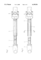
- FIG. 1 is a front view of a steering shaft according to the present invention
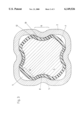
- FIG. 2 is a cross-sectional view of the steering shaft shown in FIG. 1;
- FIG. 3. is a cross-sectional view taken along line III--III in FIG. 2 at an enlarged scale
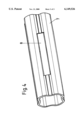
- FIG. 4 is a perspective view of a slide sleeve forming part of the steering shaft according to the present invention.
- a steering shaft according to the present invention and shown in FIGS. 1 through 3 includes a first profile member 1 having a solid cross-section and carrying, at one of its opposite ends, a shaped part 3 to which further components of a steering assembly, which do not form part of the present invention and which are not shown in the drawings, are to be attached.
- the profile member 1, which is formed as a profile bar the cross-section of which is shown in FIG. 3, can be produced by rolling, cold pressing or cold drawing from a solid material.
- the cross-section of the profile member 1 is formed with rounded corner areas between which press-in grooves are formed. Between the corner areas and the respective pressed-in groove, the profile member has continuous curved transition areas.
- the steering shaft further includes a second profile member 2 which is formed as a tubular part and carries at its end, which is opposite to the end of the first profile member 1 carrying the shaped part 3, a hinge part 6.
- the tubular profile member 2 has a cross-section which approximately matches the cross-section of the profile member 1.
- the cross-section of the profile member 2 likewise has rounded corner areas with pressed-in grooves therebetween. As in the profile member 1, continuous curved transitional areas are provided between the corner areas and the pressed-in grooves in the profile member 2.
- each of the profile members 1 and 2 is formed by following one another curved sections, namely, convex and concave sections.
- the radii of curvature of the curved sections of respective circumferential contours are alternatively positioned inside and outside of the respective profile members 1 and 2.
- the individual radii of curvature of each circumferential contour differ in size, as can be seen in FIG. 3.
- the inside dimensions of the external profile member 2 and the outside dimensions of the internal profile member 1 differ to such an extent that a noticeable clearance is formed between them.
- the clearance between the two profile members 1 and 2 defines a circumferential gap having a variable width along its circumference.
- a slide sleeve 7, which is formed of a suitable macromolecular or plastic material having a low friction coefficient is secured on the internal profile member 1, as shown in FIG. 3.
- the circumferential contour of the sliding sleeve 7 substantially corresponds to the circumferential contour of the profile member 1.
- the slide sleeve 7 In its mounted condition on the profile member 1, the slide sleeve 7 has a circumferential contour which slightly deviates from the contour the slide sleeve 7 has in its non-mounted condition. As a result of this, the slide sleeve 7 becomes slightly deformed upon being mounted on the profile member 1, and is prestressed in its mounted condition.
- the slide sleeve 7 has substantially the same wall thickness along its entire circumference. Several such slide sleeves 7 can be arrange along the length of the steering shaft. Generally, two slide sleeves 7 spaced from each other are provided on the internal profile member 1.
- the slide sleeve 7 extends along the concave sections of the profile member 1 with a clearance. Transition zones 12 and 13 are formed at both the internal profile member 1 and the external profile member 2. The transition zones 12 and 13 define tangentional areas in which the slide sleeve 7 extends with respect to the profile members 1 and 2 with a clearance before abutting the profile members 1 and 2.
- the clearance has a shape of a narrow curved wedge.
- the transition zones 12, 13 are located adjacent to each other radially and are angularly offset relative to each other in intermediate positions of the slide sleeve 7 with respect to the profile members 1 and 2. Viewed in the circumferential direction, the section of the slide sleeve 7 located between the transition zones 12 and 13 extends with a clearance relative to adjacent sections of the profile members 1 and 2.
- the angular offset of the transition zones 12 and 13, which are located radially adjacent to each other, is approximately 10°.
- elongate grooves 8 are formed in the slide sleeve 7. The regions of the slide sleeve, which are located on opposite sides of the groove 8, have a surface contact with the external profile member 2, as shown in FIG. 3.
- the elongate grooves 8 can have different dimensions over the length of the slide sleeve 7.
- the dimensions of the groove 8, in the middle region of the longitudinal extent of the slide sleeve 7, are greater than the dimensions of groove sections located adjacent to the end sections of the slide sleeve 7. Because of manufacturing requirements the profile members 1 and 2 and/or their surfaces have certain dimensional tolerances. Thanks to the above-discussed dimensioning of the grooves 8, only very small frictional forces are generated during a longitudinal adjustment of the steering column.
- the reduction of the wall thickness of the slide sleeve 7 due to the foregoing groove dimensioning results in a greater resiliency of the slide sleeve 7 in the area in which it acts as a compensating sleeve.
- the contact areas between the inner and outer profile members 1 and 2 and the slide sleeve 7 are reduced in comparison with similar designs of the prior art. As a result of this reduction, more favorable condition are created for sliding of the two profile members relative to each other.
- the sections of the slide sleeve 7, which are located between the transition zones 12, 13, acts like leaf springs, whereby turning of the steering wheels is associated with a certain, practically backlash-free, steering resistance. As a result, the driver, which operates the steering wheel, does not feel the backlash necessarily existing due to constructional imperfection.
- the essence of the present invention consists in that the transition zones 12, 13 are located adjacent to each other in the radial direction and are angularly offset relative to each other in the intermediate positions of the slide sleeve 7 between the positions of the slide sleeve 7, in which it lies closely to or abuts the respective sections of the profile members 1 and 2, and positions in which it extends with a clearance relative to the profile members 1, 2.
- the sections of the slide sleeve 7, which are located between respective radially adjacent transition zones 12 and 13 extend freely in the clearance space 4 and act like a spring upon application of a torque to the steering column.
Applications Claiming Priority (2)
| Application Number | Priority Date | Filing Date | Title |
|---|---|---|---|
| DE19750005A DE19750005C1 (de) | 1997-11-12 | 1997-11-12 | Längenveränderbare Lenkspindel für Lenkvorrichtungen bei Kraftfahrzeugen |
| DE19750005 | 1997-11-12 |
Publications (1)
| Publication Number | Publication Date |
|---|---|
| US6149526A true US6149526A (en) | 2000-11-21 |
Family
ID=7848412
Family Applications (1)
| Application Number | Title | Priority Date | Filing Date |
|---|---|---|---|
| US09/189,089 Expired - Lifetime US6149526A (en) | 1997-11-12 | 1998-11-09 | Variable length steering shaft for steering mechanisms of motor vehicles |
Country Status (8)
| Country | Link |
|---|---|
| US (1) | US6149526A (de) |
| EP (1) | EP0916564B1 (de) |
| JP (1) | JP4179683B2 (de) |
| CN (1) | CN1102515C (de) |
| BR (1) | BR9805547A (de) |
| DE (1) | DE19750005C1 (de) |
| ES (1) | ES2205356T3 (de) |
| HK (1) | HK1021354A1 (de) |
Cited By (28)
| Publication number | Priority date | Publication date | Assignee | Title |
|---|---|---|---|---|
| US6260433B1 (en) * | 1999-01-28 | 2001-07-17 | Eurocardan S.P.A. | Lubricating device for telescopic shaft axial conduits formed in its relatively slidable tubular parts |
| GB2380243A (en) * | 2001-08-06 | 2003-04-02 | Nsk Ltd | Adjustable steering apparatus for a car featuring a one piece column with an enlarged portion |
| US20030184135A1 (en) * | 2002-03-27 | 2003-10-02 | Bugle Clifford M. | Bicycle seat rail and method of making same |
| US6733039B2 (en) * | 2001-06-18 | 2004-05-11 | Mitsubishi Jidosha Kogyo Kabushiki Kaisha | Damper mechanism for steering device |
| US20050197192A1 (en) * | 2004-03-04 | 2005-09-08 | Hitachi Ltd. | Drive-transmission device |
| US20050268739A1 (en) * | 2002-07-17 | 2005-12-08 | Nsk Ltd. | Steering column device |
| US20060094516A1 (en) * | 2004-11-03 | 2006-05-04 | Lukac J B | Tubular telescoping drive shaft |
| US20060290127A1 (en) * | 2005-06-27 | 2006-12-28 | Cymbal William D | Telescoping steering column assembly and method of manufacturing the assembly |
| US20070105632A1 (en) * | 2004-08-26 | 2007-05-10 | Ronald Brissette | Driveshaft assembly with torque ring coupling |
| US20080000316A1 (en) * | 2006-06-29 | 2008-01-03 | Nsk Ltd. | Telescopic shaft |
| DE102007002380B3 (de) * | 2007-01-10 | 2008-06-19 | Thyssenkrupp Presta Ag | Längenveränderbare Lenkspindel |
| US20090005184A1 (en) * | 2007-06-18 | 2009-01-01 | Skf Aerospace France | Shaft for transmitting rotational movements and/or forces |
| US20090056493A1 (en) * | 2007-08-29 | 2009-03-05 | Dubay Robert W | Steering column manufacturing machine and method of manufacturing a steering column |
| US20090229504A1 (en) * | 2008-03-17 | 2009-09-17 | Hiroshi Iwakami | Steering unit for small watercraft |
| US20090249916A1 (en) * | 2008-04-04 | 2009-10-08 | Delphi Technologies, Inc. | Steering column assembly with shearable jacket connector |
| US20090270185A1 (en) * | 2006-11-10 | 2009-10-29 | Jtekt Corporation | Motor vehicle steering shaft and motor vehicle steering system |
| US20110219907A1 (en) * | 2008-10-01 | 2011-09-15 | Thyssenkrupp Presta Ag | Sliding sleeve |
| US8388455B2 (en) | 2010-12-22 | 2013-03-05 | Thyssenkrupp Presta Aktiengesellschaft | Antifriction bushing |
| US20140020502A1 (en) * | 2008-01-18 | 2014-01-23 | Thyssenkrupp Presta Ag | Steering column comprising a plastic sliding sleeve |
| US9156489B2 (en) | 2010-10-21 | 2015-10-13 | Daimler Ag | Sliding sleeve blank and motor vehicle steering spindle assembly having a sliding sleeve made from the blank |
| US20160160913A1 (en) * | 2014-12-09 | 2016-06-09 | Ford Global Technologies, Llc | Radially deflectable bushing and steering gear assembly using the same |
| CN105835940A (zh) * | 2016-03-31 | 2016-08-10 | 广州汽车集团股份有限公司 | 转向管柱及汽车转向系统 |
| US20170167591A1 (en) * | 2015-12-10 | 2017-06-15 | Toyota Jidosha Kabushiki Kaisha | Power Transmission System for Vehicle |
| US20170167592A1 (en) * | 2015-12-10 | 2017-06-15 | Toyota Jidosha Kabushiki Kaisha | Power transmission system for vehicle |
| US9771969B2 (en) | 2011-03-18 | 2017-09-26 | Jtekt Corporation | Method of manufacturing torque transmission shaft and vehicle steering apparatus |
| US9845861B1 (en) * | 2016-05-26 | 2017-12-19 | GM Global Technology Operations LLC | Rotatable assembly including a coupling interface |
| US10112641B2 (en) * | 2013-08-06 | 2018-10-30 | Adval Tech Holding Ag | Guide tube for a steering shaft and method for producing same |
| US11472467B2 (en) | 2017-06-29 | 2022-10-18 | Thyssenkrupp Presta Ag | Steering shaft for a motor vehicle and method for the production thereof |
Families Citing this family (17)
| Publication number | Priority date | Publication date | Assignee | Title |
|---|---|---|---|---|
| DE10056619A1 (de) * | 2000-11-15 | 2002-05-29 | Wiederholt V W Werk | Vorrichtung zur Höhenverstellung eines Lenkrades eines Fahrzeugs sowie zur Übertragung eines Drehmoments von dem Lenkrad auf ein Lenkgestänge |
| JP3797304B2 (ja) * | 2002-09-13 | 2006-07-19 | 日本精工株式会社 | 車両ステアリング用伸縮軸 |
| DE20317344U1 (de) * | 2003-11-11 | 2004-01-08 | Dura Automotive Systems Reiche Gmbh & Co. Kg | Teleskopierbare Lenkwelle |
| KR100991992B1 (ko) | 2005-03-21 | 2010-11-04 | 주식회사 만도 | 차량용 스티어링컬럼의 텔레스코픽부시 |
| GB2429761A (en) | 2005-09-03 | 2007-03-07 | Nsk Steering Sys Europ Ltd | Temperature accommodating vehicl steering column bush |
| WO2007069304A1 (ja) | 2005-12-13 | 2007-06-21 | Nsk Ltd. | 車両ステアリングシャフト用伸縮軸及び前記伸縮軸の潤滑用グリース組成物 |
| DE102006010228B3 (de) | 2006-03-02 | 2007-11-22 | Thyssenkrupp Presta Ag | Verfahren zur Herstellung eines Lenkspindelteils |
| EP2027397B1 (de) * | 2006-06-09 | 2019-01-30 | Süddeutsche Gelenkscheibenfabrik GmbH & Co. KG | Drehmomentübertragungseinrichtung zum schwingungsreduzierten übertragen von drehmomenten über wenigstens eine welle |
| KR100854763B1 (ko) * | 2007-03-27 | 2008-08-27 | 주식회사 만도 | 슬립 조인트 |
| DE102009038316A1 (de) | 2009-08-21 | 2011-02-24 | Thyssenkrupp Presta Ag | Verfahren zur Herstellung eines einen Abschnitt einer Lenkspindel bildenden Lenkspindelteils |
| EP2469107B1 (de) | 2010-12-21 | 2013-02-20 | ThyssenKrupp Presta Aktiengesellschaft | Gleithülse |
| DE202010017747U1 (de) | 2010-12-21 | 2012-07-10 | Thyssenkrupp Presta Aktiengesellschaft | Gleithülse |
| CN103206482A (zh) * | 2013-04-19 | 2013-07-17 | 沈阳工业大学 | 柔性摩擦换向轮 |
| JP6414661B2 (ja) * | 2013-07-03 | 2018-10-31 | 株式会社ジェイテクト | ステアリングコラム装置 |
| DE102016214163A1 (de) | 2016-08-01 | 2016-10-13 | Thyssenkrupp Ag | Verfahren zur Herstellung eines Lenkspindelteils und Lenkspindel für ein Kraftfahrzeug |
| DE102016116230A1 (de) * | 2016-08-31 | 2018-03-01 | Dr. Ing. H.C. F. Porsche Aktiengesellschaft | Teleskop-Lenkzwischenwelle |
| FR3105773A1 (fr) * | 2019-12-31 | 2021-07-02 | Robert Bosch Automotive Steering Vendôme | fourreau de colonne de direction comportant un Système de réglage d’une position relative entre deux tubes |
Citations (8)
| Publication number | Priority date | Publication date | Assignee | Title |
|---|---|---|---|---|
| US2199926A (en) * | 1937-07-19 | 1940-05-07 | Borg Warner | Resilient slip joint |
| US4020651A (en) * | 1975-07-03 | 1977-05-03 | Rexnord Inc. | Telescoping drive line |
| US4033020A (en) * | 1975-08-04 | 1977-07-05 | Trw Inc. | Method of making a slip joint |
| US4667530A (en) * | 1985-07-22 | 1987-05-26 | Etablissement Supervis | Variable length shaft assembly particularly for motor vehicle steering shafts |
| US5460574A (en) * | 1993-08-31 | 1995-10-24 | Trw Inc. | Variable length shaft assembly with a lash bushing |
| US5507203A (en) * | 1993-05-03 | 1996-04-16 | The Torrington Company | Variable length shaft assembly |
| US5902186A (en) * | 1997-08-08 | 1999-05-11 | Douglas Autotech Corp. | Intermediate shaft assembly for steering columns |
| US5919094A (en) * | 1994-10-13 | 1999-07-06 | Matsui Universal Joint Manufacturing Company | Propeller shaft |
Family Cites Families (12)
| Publication number | Priority date | Publication date | Assignee | Title |
|---|---|---|---|---|
| US2272900A (en) * | 1940-11-08 | 1942-02-10 | Firestone Tire & Rubber Co | Resilient connector |
| BE518748A (de) * | 1952-04-03 | |||
| GB1126071A (en) * | 1966-01-12 | 1968-09-05 | Birfield Eng Ltd | Improvements in or relating to vehicle steering shaft assemblies |
| FR2086647A5 (de) * | 1970-04-03 | 1971-12-31 | Citroen Sa | |
| US3703105A (en) * | 1971-08-20 | 1972-11-21 | Gen Motors Corp | Collapsible shift tube asembly |
| FR2586987B1 (fr) * | 1985-09-06 | 1990-06-01 | Peugeot Cycles | Sous-ensemble telescopique pour colonne de direction |
| DE8534668U1 (de) * | 1985-12-10 | 1986-02-06 | Reiche & Co, 4937 Lage | Teleskoprohr |
| DE4008481A1 (de) * | 1990-03-16 | 1991-09-19 | Reiche & Co | Als teleskoprohr ausgebildete, vorzugsweise durch handkraft hoehenverstellbare kraftfahrzeuglenksaeule |
| US5383811A (en) * | 1991-05-31 | 1995-01-24 | Dana Corporation | Flexible non-metallic bearing liner for telescopic steering column |
| US5477750A (en) * | 1993-05-03 | 1995-12-26 | The Torrington Company | Variable length shaft assembly |
| US5417614A (en) * | 1994-03-14 | 1995-05-23 | General Motors Corporation | Variable length shaft assembly |
| FR2737173B1 (fr) * | 1995-07-26 | 1997-10-10 | Nacam | Colonne de direction reglable en profondeur, avec dispositif de guidage |
-
1997
- 1997-11-12 DE DE19750005A patent/DE19750005C1/de not_active Expired - Fee Related
-
1998
- 1998-04-28 CN CN98107918A patent/CN1102515C/zh not_active Expired - Fee Related
- 1998-10-19 ES ES98119681T patent/ES2205356T3/es not_active Expired - Lifetime
- 1998-10-19 EP EP98119681A patent/EP0916564B1/de not_active Expired - Lifetime
- 1998-11-09 US US09/189,089 patent/US6149526A/en not_active Expired - Lifetime
- 1998-11-11 JP JP32074998A patent/JP4179683B2/ja not_active Expired - Fee Related
- 1998-11-12 BR BR9805547-0A patent/BR9805547A/pt not_active IP Right Cessation
-
2000
- 2000-01-11 HK HK00100182A patent/HK1021354A1/xx not_active IP Right Cessation
Patent Citations (8)
| Publication number | Priority date | Publication date | Assignee | Title |
|---|---|---|---|---|
| US2199926A (en) * | 1937-07-19 | 1940-05-07 | Borg Warner | Resilient slip joint |
| US4020651A (en) * | 1975-07-03 | 1977-05-03 | Rexnord Inc. | Telescoping drive line |
| US4033020A (en) * | 1975-08-04 | 1977-07-05 | Trw Inc. | Method of making a slip joint |
| US4667530A (en) * | 1985-07-22 | 1987-05-26 | Etablissement Supervis | Variable length shaft assembly particularly for motor vehicle steering shafts |
| US5507203A (en) * | 1993-05-03 | 1996-04-16 | The Torrington Company | Variable length shaft assembly |
| US5460574A (en) * | 1993-08-31 | 1995-10-24 | Trw Inc. | Variable length shaft assembly with a lash bushing |
| US5919094A (en) * | 1994-10-13 | 1999-07-06 | Matsui Universal Joint Manufacturing Company | Propeller shaft |
| US5902186A (en) * | 1997-08-08 | 1999-05-11 | Douglas Autotech Corp. | Intermediate shaft assembly for steering columns |
Cited By (52)
| Publication number | Priority date | Publication date | Assignee | Title |
|---|---|---|---|---|
| US6260433B1 (en) * | 1999-01-28 | 2001-07-17 | Eurocardan S.P.A. | Lubricating device for telescopic shaft axial conduits formed in its relatively slidable tubular parts |
| US6733039B2 (en) * | 2001-06-18 | 2004-05-11 | Mitsubishi Jidosha Kogyo Kabushiki Kaisha | Damper mechanism for steering device |
| US7228754B2 (en) | 2001-08-06 | 2007-06-12 | Nsk Ltd. | Steering apparatus for a car and method of manufacturing the same |
| GB2380243B (en) * | 2001-08-06 | 2005-12-28 | Nsk Ltd | Steering apparatus for a car and method of manufacturing the same |
| GB2380243A (en) * | 2001-08-06 | 2003-04-02 | Nsk Ltd | Adjustable steering apparatus for a car featuring a one piece column with an enlarged portion |
| US20050160863A1 (en) * | 2001-08-06 | 2005-07-28 | Nsk Ltd. | Steering apparatus for a car and method of manufacturing the same |
| US20050040683A1 (en) * | 2002-03-27 | 2005-02-24 | Bugle Clifford M. | Bicycle seat rail and method of making same |
| US7125072B2 (en) * | 2002-03-27 | 2006-10-24 | Dynamet Holdings, Inc. | Bicycle seat rail and method of making same |
| US20030184135A1 (en) * | 2002-03-27 | 2003-10-02 | Bugle Clifford M. | Bicycle seat rail and method of making same |
| US20050268739A1 (en) * | 2002-07-17 | 2005-12-08 | Nsk Ltd. | Steering column device |
| US20050197192A1 (en) * | 2004-03-04 | 2005-09-08 | Hitachi Ltd. | Drive-transmission device |
| CN100383415C (zh) * | 2004-03-04 | 2008-04-23 | 株式会社日立制作所 | 动力传动装置 |
| US20070105632A1 (en) * | 2004-08-26 | 2007-05-10 | Ronald Brissette | Driveshaft assembly with torque ring coupling |
| US20070015593A1 (en) * | 2004-11-03 | 2007-01-18 | Lukac J B | Tubular telescoping drive shaft |
| US20070015592A1 (en) * | 2004-11-03 | 2007-01-18 | Lukac J B | Tubular telescoping drive shaft |
| US20060094516A1 (en) * | 2004-11-03 | 2006-05-04 | Lukac J B | Tubular telescoping drive shaft |
| US7238113B2 (en) | 2004-11-03 | 2007-07-03 | Cnh America Llc | Tubular telescoping drive shaft |
| US7207890B2 (en) | 2004-11-03 | 2007-04-24 | Cnh America Llc | Tubular telescoping drive shaft |
| US7556293B2 (en) | 2005-06-27 | 2009-07-07 | Delphi Technologies, Inc. | Telescoping steering column assembly and method of manufacturing the assembly |
| US20060290127A1 (en) * | 2005-06-27 | 2006-12-28 | Cymbal William D | Telescoping steering column assembly and method of manufacturing the assembly |
| US20080000316A1 (en) * | 2006-06-29 | 2008-01-03 | Nsk Ltd. | Telescopic shaft |
| US7559266B2 (en) | 2006-06-29 | 2009-07-14 | Nsk Ltd. | Telescopic shaft |
| US8052535B2 (en) * | 2006-11-10 | 2011-11-08 | Jtekt Corporation | Motor vehicle steering shaft and motor vehicle steering system |
| US20090270185A1 (en) * | 2006-11-10 | 2009-10-29 | Jtekt Corporation | Motor vehicle steering shaft and motor vehicle steering system |
| DE102007002380B3 (de) * | 2007-01-10 | 2008-06-19 | Thyssenkrupp Presta Ag | Längenveränderbare Lenkspindel |
| US8435124B2 (en) | 2007-01-10 | 2013-05-07 | Thyssenkrupp Presta Aktiengesellschaft | Variable length steering spindle |
| WO2008083829A1 (de) | 2007-01-10 | 2008-07-17 | Thyssenkrupp Presta Aktiengesellschaft | Längenveränderbare lenkspindel |
| US20090005184A1 (en) * | 2007-06-18 | 2009-01-01 | Skf Aerospace France | Shaft for transmitting rotational movements and/or forces |
| US8025580B2 (en) * | 2007-06-18 | 2011-09-27 | Skf Aerospace France | Shaft for transmitting rotational movements and/or forces |
| US8783128B2 (en) | 2007-08-29 | 2014-07-22 | Steering Solutions Ip Holding Corporation | Steering column manufacturing machine and method of manufacturing a steering column |
| US20090056493A1 (en) * | 2007-08-29 | 2009-03-05 | Dubay Robert W | Steering column manufacturing machine and method of manufacturing a steering column |
| US8096036B2 (en) | 2007-08-29 | 2012-01-17 | Nexteer (Beijing) Technology Co., Ltd. | Method of manufacturing a steering column |
| US8714048B2 (en) * | 2008-01-18 | 2014-05-06 | Thyssenkrupp Presta Ag | Steering column comprising a plastic sliding sleeve |
| US20140020502A1 (en) * | 2008-01-18 | 2014-01-23 | Thyssenkrupp Presta Ag | Steering column comprising a plastic sliding sleeve |
| US8042481B2 (en) * | 2008-03-17 | 2011-10-25 | Honda Motor Co., Ltd. | Steering unit for small watercraft |
| US20090229504A1 (en) * | 2008-03-17 | 2009-09-17 | Hiroshi Iwakami | Steering unit for small watercraft |
| US8627742B2 (en) * | 2008-04-04 | 2014-01-14 | Steering Solutions Ip Holding Corporation | Steering column assembly with shearable jacket connector |
| US20090249916A1 (en) * | 2008-04-04 | 2009-10-08 | Delphi Technologies, Inc. | Steering column assembly with shearable jacket connector |
| US9010215B2 (en) * | 2008-10-01 | 2015-04-21 | Thyssenkrupp Presta Ag | Sliding sleeve |
| US20110219907A1 (en) * | 2008-10-01 | 2011-09-15 | Thyssenkrupp Presta Ag | Sliding sleeve |
| US9156489B2 (en) | 2010-10-21 | 2015-10-13 | Daimler Ag | Sliding sleeve blank and motor vehicle steering spindle assembly having a sliding sleeve made from the blank |
| US8388455B2 (en) | 2010-12-22 | 2013-03-05 | Thyssenkrupp Presta Aktiengesellschaft | Antifriction bushing |
| US9771969B2 (en) | 2011-03-18 | 2017-09-26 | Jtekt Corporation | Method of manufacturing torque transmission shaft and vehicle steering apparatus |
| US10112641B2 (en) * | 2013-08-06 | 2018-10-30 | Adval Tech Holding Ag | Guide tube for a steering shaft and method for producing same |
| US20160160913A1 (en) * | 2014-12-09 | 2016-06-09 | Ford Global Technologies, Llc | Radially deflectable bushing and steering gear assembly using the same |
| US10100873B2 (en) * | 2014-12-09 | 2018-10-16 | Ford Global Technologies, Llc | Radially deflectable bushing and steering gear assembly using the same |
| US20170167591A1 (en) * | 2015-12-10 | 2017-06-15 | Toyota Jidosha Kabushiki Kaisha | Power Transmission System for Vehicle |
| US20170167592A1 (en) * | 2015-12-10 | 2017-06-15 | Toyota Jidosha Kabushiki Kaisha | Power transmission system for vehicle |
| US10001206B2 (en) * | 2015-12-10 | 2018-06-19 | Toyota Jidosha Kabushiki Kaisha | Power transmission system for vehicle |
| CN105835940A (zh) * | 2016-03-31 | 2016-08-10 | 广州汽车集团股份有限公司 | 转向管柱及汽车转向系统 |
| US9845861B1 (en) * | 2016-05-26 | 2017-12-19 | GM Global Technology Operations LLC | Rotatable assembly including a coupling interface |
| US11472467B2 (en) | 2017-06-29 | 2022-10-18 | Thyssenkrupp Presta Ag | Steering shaft for a motor vehicle and method for the production thereof |
Also Published As
| Publication number | Publication date |
|---|---|
| JP4179683B2 (ja) | 2008-11-12 |
| DE19750005C1 (de) | 1999-04-22 |
| CN1223212A (zh) | 1999-07-21 |
| CN1102515C (zh) | 2003-03-05 |
| EP0916564B1 (de) | 2003-08-13 |
| BR9805547A (pt) | 1999-11-03 |
| HK1021354A1 (en) | 2000-06-09 |
| EP0916564A1 (de) | 1999-05-19 |
| ES2205356T3 (es) | 2004-05-01 |
| JPH11208484A (ja) | 1999-08-03 |
Similar Documents
| Publication | Publication Date | Title |
|---|---|---|
| US6149526A (en) | Variable length steering shaft for steering mechanisms of motor vehicles | |
| US4705491A (en) | Telescopic guide, especially for transmittance of torque | |
| US4667530A (en) | Variable length shaft assembly particularly for motor vehicle steering shafts | |
| JP4419841B2 (ja) | 車両ステアリング用伸縮軸 | |
| US5709605A (en) | Shaft coupling | |
| US7290800B2 (en) | Telescoping steering shaft | |
| US6510756B2 (en) | Ball spline joint and intermediate shaft for use in a steering column assembly | |
| US7234693B2 (en) | Bearing for a motor vehicle | |
| US7322607B2 (en) | Telescopic shaft for steering vehicle and telescopic shaft for steering vehicle with cardan shaft coupling | |
| EP1553005B1 (de) | Ausfahrbare fahrzeuglenkspindel | |
| JPH026362B2 (de) | ||
| US5954317A (en) | Hydraulically damping rubber bearing | |
| JPWO2004062981A1 (ja) | 車両ステアリング用伸縮軸 | |
| US6270418B1 (en) | Elastic shaft joint | |
| GB2297818A (en) | A chain roller having grooves which prevent axial expansion when the roller is pressed through a sizing die | |
| US7174803B2 (en) | Steering shaft for motor vehicles | |
| EP0950823B1 (de) | Homokinetisches Kreuzgelenk | |
| US20180154922A1 (en) | Intermediate Steering Shaft for a Motor Vehicle, and Method for Operating an Intermediate Steering Shaft for a Motor Vehicle | |
| EP1548310A1 (de) | Kreuzkupplung | |
| KR20090049018A (ko) | 유니버설 조인트 | |
| JPS6234028Y2 (de) | ||
| JP2005114068A (ja) | スプライン継手 | |
| KR100380244B1 (ko) | 자동차의 조향축용 유니버셜 조인트의 유격 보상구조 | |
| JP3624301B2 (ja) | ラックピニオン式舵取装置 | |
| JP2005306216A (ja) | 車両用ステアリングシステム |
Legal Events
| Date | Code | Title | Description |
|---|---|---|---|
| AS | Assignment |
Owner name: ETABLISSEMENT SUPERVIS, LIECHTENSTEIN Free format text: ASSIGNMENT OF ASSIGNORS INTEREST;ASSIGNORS:BOERSMA, JOSEF SAPE;MUNTENER, HERBERT;REEL/FRAME:009583/0641 Effective date: 19981020 |
|
| STCF | Information on status: patent grant |
Free format text: PATENTED CASE |
|
| FPAY | Fee payment |
Year of fee payment: 4 |
|
| FPAY | Fee payment |
Year of fee payment: 8 |
|
| FPAY | Fee payment |
Year of fee payment: 12 |