US5507203A - Variable length shaft assembly - Google Patents
Variable length shaft assembly Download PDFInfo
- Publication number
- US5507203A US5507203A US08/428,509 US42850995A US5507203A US 5507203 A US5507203 A US 5507203A US 42850995 A US42850995 A US 42850995A US 5507203 A US5507203 A US 5507203A
- Authority
- US
- United States
- Prior art keywords
- spring
- shaft member
- peripheral wall
- axially extending
- region
- Prior art date
- Legal status (The legal status is an assumption and is not a legal conclusion. Google has not performed a legal analysis and makes no representation as to the accuracy of the status listed.)
- Expired - Lifetime
Links
- 230000008878 coupling Effects 0.000 claims abstract description 24
- 238000010168 coupling process Methods 0.000 claims abstract description 24
- 238000005859 coupling reaction Methods 0.000 claims abstract description 24
- 230000002093 peripheral effect Effects 0.000 claims abstract description 16
- 230000000295 complement effect Effects 0.000 claims abstract description 9
- 230000036316 preload Effects 0.000 claims description 5
- 230000001747 exhibiting effect Effects 0.000 claims 1
- 230000000712 assembly Effects 0.000 description 2
- 238000000429 assembly Methods 0.000 description 2
- 230000005540 biological transmission Effects 0.000 description 2
- 230000000694 effects Effects 0.000 description 2
- 238000010586 diagram Methods 0.000 description 1
- 238000009434 installation Methods 0.000 description 1
- 238000004519 manufacturing process Methods 0.000 description 1
Images


Classifications
-
- B—PERFORMING OPERATIONS; TRANSPORTING
- B62—LAND VEHICLES FOR TRAVELLING OTHERWISE THAN ON RAILS
- B62D—MOTOR VEHICLES; TRAILERS
- B62D1/00—Steering controls, i.e. means for initiating a change of direction of the vehicle
- B62D1/02—Steering controls, i.e. means for initiating a change of direction of the vehicle vehicle-mounted
- B62D1/16—Steering columns
- B62D1/18—Steering columns yieldable or adjustable, e.g. tiltable
- B62D1/185—Steering columns yieldable or adjustable, e.g. tiltable adjustable by axial displacement, e.g. telescopically
-
- F—MECHANICAL ENGINEERING; LIGHTING; HEATING; WEAPONS; BLASTING
- F16—ENGINEERING ELEMENTS AND UNITS; GENERAL MEASURES FOR PRODUCING AND MAINTAINING EFFECTIVE FUNCTIONING OF MACHINES OR INSTALLATIONS; THERMAL INSULATION IN GENERAL
- F16C—SHAFTS; FLEXIBLE SHAFTS; ELEMENTS OR CRANKSHAFT MECHANISMS; ROTARY BODIES OTHER THAN GEARING ELEMENTS; BEARINGS
- F16C3/00—Shafts; Axles; Cranks; Eccentrics
- F16C3/02—Shafts; Axles
- F16C3/03—Shafts; Axles telescopic
-
- F—MECHANICAL ENGINEERING; LIGHTING; HEATING; WEAPONS; BLASTING
- F16—ENGINEERING ELEMENTS AND UNITS; GENERAL MEASURES FOR PRODUCING AND MAINTAINING EFFECTIVE FUNCTIONING OF MACHINES OR INSTALLATIONS; THERMAL INSULATION IN GENERAL
- F16D—COUPLINGS FOR TRANSMITTING ROTATION; CLUTCHES; BRAKES
- F16D3/00—Yielding couplings, i.e. with means permitting movement between the connected parts during the drive
- F16D3/02—Yielding couplings, i.e. with means permitting movement between the connected parts during the drive adapted to specific functions
- F16D3/06—Yielding couplings, i.e. with means permitting movement between the connected parts during the drive adapted to specific functions specially adapted to allow axial displacement
-
- F—MECHANICAL ENGINEERING; LIGHTING; HEATING; WEAPONS; BLASTING
- F16—ENGINEERING ELEMENTS AND UNITS; GENERAL MEASURES FOR PRODUCING AND MAINTAINING EFFECTIVE FUNCTIONING OF MACHINES OR INSTALLATIONS; THERMAL INSULATION IN GENERAL
- F16D—COUPLINGS FOR TRANSMITTING ROTATION; CLUTCHES; BRAKES
- F16D3/00—Yielding couplings, i.e. with means permitting movement between the connected parts during the drive
- F16D3/50—Yielding couplings, i.e. with means permitting movement between the connected parts during the drive with the coupling parts connected by one or more intermediate members
- F16D3/56—Yielding couplings, i.e. with means permitting movement between the connected parts during the drive with the coupling parts connected by one or more intermediate members comprising elastic metal lamellae, elastic rods, or the like, e.g. arranged radially or parallel to the axis, the members being shear-loaded collectively by the total load
-
- F—MECHANICAL ENGINEERING; LIGHTING; HEATING; WEAPONS; BLASTING
- F16—ENGINEERING ELEMENTS AND UNITS; GENERAL MEASURES FOR PRODUCING AND MAINTAINING EFFECTIVE FUNCTIONING OF MACHINES OR INSTALLATIONS; THERMAL INSULATION IN GENERAL
- F16D—COUPLINGS FOR TRANSMITTING ROTATION; CLUTCHES; BRAKES
- F16D3/00—Yielding couplings, i.e. with means permitting movement between the connected parts during the drive
- F16D3/50—Yielding couplings, i.e. with means permitting movement between the connected parts during the drive with the coupling parts connected by one or more intermediate members
- F16D3/64—Yielding couplings, i.e. with means permitting movement between the connected parts during the drive with the coupling parts connected by one or more intermediate members comprising elastic elements arranged between substantially-radial walls of both coupling parts
- F16D3/66—Yielding couplings, i.e. with means permitting movement between the connected parts during the drive with the coupling parts connected by one or more intermediate members comprising elastic elements arranged between substantially-radial walls of both coupling parts the elements being metallic, e.g. in the form of coils
-
- F—MECHANICAL ENGINEERING; LIGHTING; HEATING; WEAPONS; BLASTING
- F16—ENGINEERING ELEMENTS AND UNITS; GENERAL MEASURES FOR PRODUCING AND MAINTAINING EFFECTIVE FUNCTIONING OF MACHINES OR INSTALLATIONS; THERMAL INSULATION IN GENERAL
- F16F—SPRINGS; SHOCK-ABSORBERS; MEANS FOR DAMPING VIBRATION
- F16F15/00—Suppression of vibrations in systems; Means or arrangements for avoiding or reducing out-of-balance forces, e.g. due to motion
- F16F15/10—Suppression of vibrations in rotating systems by making use of members moving with the system
- F16F15/12—Suppression of vibrations in rotating systems by making use of members moving with the system using elastic members or friction-damping members, e.g. between a rotating shaft and a gyratory mass mounted thereon
- F16F15/121—Suppression of vibrations in rotating systems by making use of members moving with the system using elastic members or friction-damping members, e.g. between a rotating shaft and a gyratory mass mounted thereon using springs as elastic members, e.g. metallic springs
- F16F15/124—Elastomeric springs
- F16F15/126—Elastomeric springs consisting of at least one annular element surrounding the axis of rotation
-
- F—MECHANICAL ENGINEERING; LIGHTING; HEATING; WEAPONS; BLASTING
- F16—ENGINEERING ELEMENTS AND UNITS; GENERAL MEASURES FOR PRODUCING AND MAINTAINING EFFECTIVE FUNCTIONING OF MACHINES OR INSTALLATIONS; THERMAL INSULATION IN GENERAL
- F16C—SHAFTS; FLEXIBLE SHAFTS; ELEMENTS OR CRANKSHAFT MECHANISMS; ROTARY BODIES OTHER THAN GEARING ELEMENTS; BEARINGS
- F16C2326/00—Articles relating to transporting
- F16C2326/20—Land vehicles
- F16C2326/24—Steering systems, e.g. steering rods or columns
Definitions
- This invention relates generally to shaft assemblies which are variable in length and more particularly to a shaft assembly which is adaptable for use as the steering shaft in steering devices of motor vehicles.
- the shaft assembly which is attached to the steering column at one end and the steering gear at the other end, must be extended axially in order to be installed to its nominal working position. Therefore, a low force to slide is essential for ease of installation.
- An additional requirement for the shaft assembly is the ability to accommodate any body/chassis flex due to road conditions.
- a steering shaft coupling comprising: an outer tubular shaft member, a coaxial inner shaft member slidably inserted within the outer tubular shaft member, the outer tubular shaft member having an inner peripheral wall and the inner shaft member having an outer peripheral wall, the inner peripheral wall and the outer peripheral wall having complementary shapes, the complementary shapes transmitting torque between the shaft members, and a biasing member between the inner shaft member and the outer tubular shaft member, the biasing member causing a force opposing the transmitted torque.
- FIG. 1 is a diagrammatical illustration of the steering system of an automobile in which a coupling of the present invention is applied;
- FIG. 2 is a perspective view of a coupling embodying the present invention
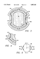
- FIG. 3 is a cross-sectional view of the coupling of FIG. 2;
- FIG. 4 is a cross-sectional view similar to FIG. 3 showing the coupling with maximum relative rotation between the upper and lower portions of the steering shaft;
- FIG. 5 is a schematic diagram showing the action of the spring forces
- FIG. 6 is a graph showing the spring load versus spring deflection of the coupling shown in FIG. 2.
- FIG. 1 shows an steering shaft coupling 1 of the present invention applied to the steering system of an automobile.
- the steering shaft coupling 1 is interposed between a steering main shaft 7 extending from a steering column 6 and a steering gear shaft 9 attached to a steering gear case 8.
- the steering shaft coupling 1 is connected to the steering main shaft 7 and the steering gear shaft 9 by a pair of universal joints 10, 11.
- FIG. 2 shows a perspective view of the coupling 1 of the present invention. Portions of the coupling 1 have been removed to show the details of the coupling 1.
- the coupling 1 is comprised of three main components, an outer tubular shaft member 20, an inner shaft member 24 and a spring member 22 located between the outer shaft member 20 and the inner shaft member 24.
- the inner shaft member 24 and the outer shaft member 20 are slidable relative to one another.
- the spring member 22 is fixed relative to one of the two shaft members.
- a lower shaft 30 is connected to the inner shaft member 24.
- the outer shaft member 20 may be axially extended such that universal joint 10 is attached directly to the outer shaft member 20.
- An upper shaft member (not shown) may be used to connect the outer shaft member 20 to the universal joint 10.
- the lower shaft 30 is slidable within the inner shaft member 24. This permits the lower and upper portions of the shaft assembly to collapse, either for ease of assembly or during a collision of the automobile.
- the lower shaft 30 has a double - D shape which permits transmission of torque between the inner shaft member 24 and the lower shaft 30.
- the outer shaft member 20, the inner shaft member 24 and the spring member 22 each have shape similar to a double - B.
- the inner peripheral wall of the outer shaft member 20 and the outer peripheral wall of the inner shaft member 24 have complementary shapes thereby permitting the transmission of rotational torque between the outer shaft member 20 and the inner shaft member 24.
- the spring member 22 will also have a shape similar to the shapes of the outer shaft member 20 and the inner shaft member 24.
- the shape of the members shown in FIGS. 2 and 3 can be described as a two toothed spline.
- the spring member 22 is formed of two sections as shown in FIG. 3. Also shown only in FIG. 3 is an anti-rattle bump 26 on opposite sides of the spring member 22.
- the anti-rattle bump 26 may be needed in some applications remove any looseness between the spring member 22 and the outer shaft member 20 along the curved portions of the outer shaft member 20.
- the purpose of the spring member 22 is to take up the rotational clearance between the outer shaft member 20 and the inner shaft member 24. As one shaft member rotates relative to the other shaft member, the spring member exerts a force 40, illustrated in FIG. 5, opposing the transmitted torque. Depending upon the shapes of the shaft members 20, 24 and the spring member 22, any number of spring forces 40 may be generated. For the embodiment shown in FIGS. 2 and 3, two spring forces are generated for clockwise rotation and two spring forces are generated for counterclockwise rotation as shown in FIG. 5. In the preferred embodiment, a line 42 normal to the spring force 40 intersects the axis of the inner shaft member.
- An object of this invention is to limit the stress in the spring member 22 as one shaft member rotates relative to the other shaft member.
- the torque transmitting shapes of the outer shaft member 20, the spring member 22 and the inner shaft member 24 are designed such that as rotational torque begins to be transmitted from one shaft member to the other shaft member through the spring member 22, stress in the spring increases and a spring force opposing the transmitted torque is generated.
- the spring member 22 becomes "sandwiched" between the outer shaft member 20 and the inner shaft member 24, as shown in FIG. 4. Once this occurs, torque is then transmitted directly from one shaft member to the other. The tensile stress in the spring member 22 no longer increases with increasing torque once this point has been reached.
- the "sandwiching" of the spring member 22 occurs along a line 28, rather than over broad areas of the spring member 22.
- FIG. 4 shows the “sandwiching” occurring in the region of spring member 22 which generates the spring force
- the “sandwiching” can occur in other regions of the spring member 22 depending upon the geometric shapes of the shaft members 20, 24 and the spring member 22.
- the spring member 22 usually carries some torque and carries the normal driving loads of the steering column. However, in higher torque and stress conditions, the "sandwiching" effect limits or caps the maximum stress in the spring member 22.
- Another object of the spring member 22 is to minimize the axial sliding load variations between the two shafts.
- a further object of the spring member 22 is to maintain a predefined relationship between the torsional rate and the axial sliding load.
- FIG. 6 which shows the relationship between spring load and spring deflection in a coupling 1 of the present invention illustrates how these objectives are achieved.
- the graph in FIG. 6 shows three different regions of spring operation. In the first region, as the spring is initially loaded, the spring load increases as spring deflection increases. In the second region, the spring load remains essentially constant as spring deflection increases. Then the coupling 1 enters the third region where the spring load again increases with increasing spring deflection or coupling loading. The spring load increases until the spring member 22 is "sandwiched" between the inner shaft member 24 and the outer shaft member 20, as shown in FIG. 4.
- the spring rate of a spring is defined as the change in the spring load for a given change in the spring deflection.
- the second region on the graph shown in FIG. 6 illustrates a low spring rate.
- the initial loading (pre-load) of the spring members 22 in coupling 1 is chosen such that the pre-load falls in this second region of low spring rate.
- the spring rate curve of coupling 1 is designed to provide a given rate to slip by providing a pre-determined assembled spring preload.
Abstract
Description
Claims (5)
Priority Applications (1)
| Application Number | Priority Date | Filing Date | Title |
|---|---|---|---|
| US08/428,509 US5507203A (en) | 1993-05-03 | 1995-04-25 | Variable length shaft assembly |
Applications Claiming Priority (2)
| Application Number | Priority Date | Filing Date | Title |
|---|---|---|---|
| US5533793A | 1993-05-03 | 1993-05-03 | |
| US08/428,509 US5507203A (en) | 1993-05-03 | 1995-04-25 | Variable length shaft assembly |
Related Parent Applications (1)
| Application Number | Title | Priority Date | Filing Date |
|---|---|---|---|
| US5533793A Continuation | 1993-05-03 | 1993-05-03 |
Publications (1)
| Publication Number | Publication Date |
|---|---|
| US5507203A true US5507203A (en) | 1996-04-16 |
Family
ID=21997180
Family Applications (1)
| Application Number | Title | Priority Date | Filing Date |
|---|---|---|---|
| US08/428,509 Expired - Lifetime US5507203A (en) | 1993-05-03 | 1995-04-25 | Variable length shaft assembly |
Country Status (10)
| Country | Link |
|---|---|
| US (1) | US5507203A (en) |
| EP (1) | EP0775265B1 (en) |
| JP (1) | JPH08511850A (en) |
| CN (1) | CN1046018C (en) |
| AU (1) | AU6669994A (en) |
| BR (1) | BR9406388A (en) |
| CA (1) | CA2160997A1 (en) |
| DE (1) | DE69419531T2 (en) |
| ES (1) | ES2133560T3 (en) |
| WO (1) | WO1994025766A1 (en) |
Cited By (27)
| Publication number | Priority date | Publication date | Assignee | Title |
|---|---|---|---|---|
| USD379610S (en) * | 1996-04-16 | 1997-06-03 | Freightliner Corporation | Truck steering wheel column cover |
| US5878832A (en) * | 1997-08-13 | 1999-03-09 | General Motors Corporation | Steering apparatus for motor vehicle |
| FR2778215A1 (en) * | 1998-04-30 | 1999-11-05 | Walterscheid Gmbh Gkn | Shaft and hub arrangement for shaft drive to rotary grass cutter |
| US6062982A (en) * | 1998-05-12 | 2000-05-16 | Trw Inc. | Force transmitting apparatus |
| US6149526A (en) * | 1997-11-12 | 2000-11-21 | Etablissement Supervis | Variable length steering shaft for steering mechanisms of motor vehicles |
| US6241616B1 (en) * | 1999-05-20 | 2001-06-05 | Neapco Inc. | Variable length double telescoping drive shaft assembly |
| US6283867B1 (en) * | 1999-12-07 | 2001-09-04 | Koyo Seiko Co., Ltd. | Elastic shaft joint |
| US6729648B2 (en) | 2002-06-07 | 2004-05-04 | Sealy Technology Llc | Non-linear energy absorbing column assembly |
| US6733039B2 (en) * | 2001-06-18 | 2004-05-11 | Mitsubishi Jidosha Kogyo Kabushiki Kaisha | Damper mechanism for steering device |
| US20040222623A1 (en) * | 2003-05-05 | 2004-11-11 | Walters Paul A. | Sealing assembly for a steering column assembly |
| US20050087970A1 (en) * | 2003-10-23 | 2005-04-28 | Anchor Tool & Die Company | Axially adjustable steering column assembly with flexible bearing sleeve |
| US20060230865A1 (en) * | 2004-01-28 | 2006-10-19 | Melchor Daumal Castellon | Intermediate shaft with low sliding load for the steering column of a motor vehicle |
| US20060290127A1 (en) * | 2005-06-27 | 2006-12-28 | Cymbal William D | Telescoping steering column assembly and method of manufacturing the assembly |
| US20070012277A1 (en) * | 2005-07-14 | 2007-01-18 | Borgwarner Inc. | Torsional damper for balance shafts |
| GB2429438A (en) * | 2005-08-25 | 2007-02-28 | Nsk Steering Sys Europ Ltd | Telescopic assembly, in particular a vehicle steering column assembly |
| US20080000316A1 (en) * | 2006-06-29 | 2008-01-03 | Nsk Ltd. | Telescopic shaft |
| US20090005184A1 (en) * | 2007-06-18 | 2009-01-01 | Skf Aerospace France | Shaft for transmitting rotational movements and/or forces |
| US20090042657A1 (en) * | 2006-07-11 | 2009-02-12 | Bayerische Motoren Werke Aktiengesellschaft | Torque Transmission Device |
| US20090056493A1 (en) * | 2007-08-29 | 2009-03-05 | Dubay Robert W | Steering column manufacturing machine and method of manufacturing a steering column |
| US20140150596A1 (en) * | 2011-07-26 | 2014-06-05 | Nsk, Ltd. | Manufacturing method for a steering column, and steering apparatus that uses that steering column |
| US9080598B2 (en) | 2013-06-26 | 2015-07-14 | Cnh Industrial America Llc | Double sided double telescoping drive coupling |
| US20160123376A1 (en) * | 2013-06-05 | 2016-05-05 | Daimler Ag | Telescopic drive shaft |
| US9643266B1 (en) * | 2006-10-27 | 2017-05-09 | Battenfeld Technologies, Inc. | Extendable folding saw |
| US20190202489A1 (en) * | 2017-12-29 | 2019-07-04 | Saint-Gobain Performance Plastics Pampus Gmbh | Steering assembly |
| US10451218B2 (en) * | 2014-05-23 | 2019-10-22 | Westport Power Inc. | Bracketed support for a double walled cryogenic storage vessel |
| US10926789B2 (en) * | 2017-12-29 | 2021-02-23 | Saint-Gobain Performance Plastics Rencol Limited | Steering assembly |
| US11092190B2 (en) | 2016-06-17 | 2021-08-17 | Thyssenkrupp Presta Ag | Telescopic steering shaft with a pull-out safeguard |
Families Citing this family (8)
| Publication number | Priority date | Publication date | Assignee | Title |
|---|---|---|---|---|
| JP3329252B2 (en) * | 1997-02-26 | 2002-09-30 | トヨタ自動車株式会社 | Connection structure of rotating shaft |
| JP3853150B2 (en) * | 1999-12-02 | 2006-12-06 | 株式会社ジェイテクト | Telescopic shaft |
| US6773199B2 (en) * | 2002-02-28 | 2004-08-10 | Gkn Walterscheid Gmbh | Coupling, especially torque limiting coupling |
| KR20090017562A (en) * | 2006-06-09 | 2009-02-18 | 에스게에프 쥐트도이췌 겔렌크솨이벤파브릭 게엠베하 & 체오, 케게 | Torque transmission device for the low vibration transmission of torque via at least one shaft |
| JP5055908B2 (en) * | 2006-09-13 | 2012-10-24 | 株式会社ジェイテクト | Power transmission structure |
| JP6132154B2 (en) * | 2013-07-18 | 2017-05-24 | 株式会社ジェイテクト | Sliding shaft and steering device |
| CN105306633B (en) * | 2015-10-23 | 2017-12-05 | 温州神一轴业有限公司 | A kind of mobile phone guide rail Minisize axial |
| CN112109796A (en) * | 2020-10-12 | 2020-12-22 | 坤泰车辆系统(常州)有限公司 | Steering column of automatic driving vehicle |
Citations (15)
| Publication number | Priority date | Publication date | Assignee | Title |
|---|---|---|---|---|
| FR1199734A (en) * | 1957-07-08 | 1959-12-16 | Thomson Houston Comp Francaise | Improvements to the assembly of rotating shafts |
| FR1239096A (en) * | 1958-10-24 | 1960-08-19 | Improvement of tubular shafts, more particularly for cardan shafts of agricultural machines | |
| US3665777A (en) * | 1969-12-15 | 1972-05-30 | Ford Motor Co | Energy absorbing steering column |
| GB1351780A (en) * | 1971-07-27 | 1974-05-01 | Ford Motor Co | Collapsible steering column for a motor vehicle |
| US3808838A (en) * | 1971-07-30 | 1974-05-07 | Gkn Transmissions Ltd | Joint structures in or for rotary shafts |
| US4014219A (en) * | 1975-11-10 | 1977-03-29 | Ford Motor Company | Steering shaft coupling |
| GB2051998A (en) * | 1979-06-23 | 1981-01-21 | Walterscheid Gmbh Jean | Protective devices for drive shafts |
| US4258960A (en) * | 1976-10-06 | 1981-03-31 | Rexnord, Inc. | Wound glass filament reinforced resin slip sleeve liner |
| US4269043A (en) * | 1979-02-24 | 1981-05-26 | Toyota Jidosha Kogyo Kabushiki Kaisha | Coupling for resiliently connecting two shafts for transmission of torque |
| JPS6042155A (en) * | 1983-08-13 | 1985-03-06 | Kayaba Ind Co Ltd | Steering gear |
| DE3513340A1 (en) * | 1985-04-13 | 1986-10-23 | Daimler-Benz Ag, 7000 Stuttgart | Driving connection between a shaft and a hub |
| US4667530A (en) * | 1985-07-22 | 1987-05-26 | Etablissement Supervis | Variable length shaft assembly particularly for motor vehicle steering shafts |
| DE3813422A1 (en) * | 1988-04-21 | 1989-11-02 | Lemfoerder Metallwaren Ag | Telescopic steering shaft for motor vehicles |
| US4962944A (en) * | 1988-05-19 | 1990-10-16 | Reiche & Co. | Manually height-adjustable steering column of power vehicle |
| US5243874A (en) * | 1992-02-24 | 1993-09-14 | Pittsburgh Tubular Shafting, Inc. | Method and apparatus for telescopically assembling a pair of elongated members |
-
1994
- 1994-04-29 AU AU66699/94A patent/AU6669994A/en not_active Abandoned
- 1994-04-29 JP JP6524569A patent/JPH08511850A/en not_active Ceased
- 1994-04-29 EP EP94915438A patent/EP0775265B1/en not_active Expired - Lifetime
- 1994-04-29 WO PCT/US1994/004743 patent/WO1994025766A1/en active IP Right Grant
- 1994-04-29 BR BR9406388A patent/BR9406388A/en not_active IP Right Cessation
- 1994-04-29 CA CA002160997A patent/CA2160997A1/en not_active Abandoned
- 1994-04-29 CN CN94191966A patent/CN1046018C/en not_active Expired - Fee Related
- 1994-04-29 DE DE69419531T patent/DE69419531T2/en not_active Expired - Fee Related
- 1994-04-29 ES ES94915438T patent/ES2133560T3/en not_active Expired - Lifetime
-
1995
- 1995-04-25 US US08/428,509 patent/US5507203A/en not_active Expired - Lifetime
Patent Citations (15)
| Publication number | Priority date | Publication date | Assignee | Title |
|---|---|---|---|---|
| FR1199734A (en) * | 1957-07-08 | 1959-12-16 | Thomson Houston Comp Francaise | Improvements to the assembly of rotating shafts |
| FR1239096A (en) * | 1958-10-24 | 1960-08-19 | Improvement of tubular shafts, more particularly for cardan shafts of agricultural machines | |
| US3665777A (en) * | 1969-12-15 | 1972-05-30 | Ford Motor Co | Energy absorbing steering column |
| GB1351780A (en) * | 1971-07-27 | 1974-05-01 | Ford Motor Co | Collapsible steering column for a motor vehicle |
| US3808838A (en) * | 1971-07-30 | 1974-05-07 | Gkn Transmissions Ltd | Joint structures in or for rotary shafts |
| US4014219A (en) * | 1975-11-10 | 1977-03-29 | Ford Motor Company | Steering shaft coupling |
| US4258960A (en) * | 1976-10-06 | 1981-03-31 | Rexnord, Inc. | Wound glass filament reinforced resin slip sleeve liner |
| US4269043A (en) * | 1979-02-24 | 1981-05-26 | Toyota Jidosha Kogyo Kabushiki Kaisha | Coupling for resiliently connecting two shafts for transmission of torque |
| GB2051998A (en) * | 1979-06-23 | 1981-01-21 | Walterscheid Gmbh Jean | Protective devices for drive shafts |
| JPS6042155A (en) * | 1983-08-13 | 1985-03-06 | Kayaba Ind Co Ltd | Steering gear |
| DE3513340A1 (en) * | 1985-04-13 | 1986-10-23 | Daimler-Benz Ag, 7000 Stuttgart | Driving connection between a shaft and a hub |
| US4667530A (en) * | 1985-07-22 | 1987-05-26 | Etablissement Supervis | Variable length shaft assembly particularly for motor vehicle steering shafts |
| DE3813422A1 (en) * | 1988-04-21 | 1989-11-02 | Lemfoerder Metallwaren Ag | Telescopic steering shaft for motor vehicles |
| US4962944A (en) * | 1988-05-19 | 1990-10-16 | Reiche & Co. | Manually height-adjustable steering column of power vehicle |
| US5243874A (en) * | 1992-02-24 | 1993-09-14 | Pittsburgh Tubular Shafting, Inc. | Method and apparatus for telescopically assembling a pair of elongated members |
Cited By (39)
| Publication number | Priority date | Publication date | Assignee | Title |
|---|---|---|---|---|
| USD379610S (en) * | 1996-04-16 | 1997-06-03 | Freightliner Corporation | Truck steering wheel column cover |
| US5878832A (en) * | 1997-08-13 | 1999-03-09 | General Motors Corporation | Steering apparatus for motor vehicle |
| US6149526A (en) * | 1997-11-12 | 2000-11-21 | Etablissement Supervis | Variable length steering shaft for steering mechanisms of motor vehicles |
| FR2778215A1 (en) * | 1998-04-30 | 1999-11-05 | Walterscheid Gmbh Gkn | Shaft and hub arrangement for shaft drive to rotary grass cutter |
| US6062982A (en) * | 1998-05-12 | 2000-05-16 | Trw Inc. | Force transmitting apparatus |
| US6241616B1 (en) * | 1999-05-20 | 2001-06-05 | Neapco Inc. | Variable length double telescoping drive shaft assembly |
| US6283867B1 (en) * | 1999-12-07 | 2001-09-04 | Koyo Seiko Co., Ltd. | Elastic shaft joint |
| US6733039B2 (en) * | 2001-06-18 | 2004-05-11 | Mitsubishi Jidosha Kogyo Kabushiki Kaisha | Damper mechanism for steering device |
| US6729648B2 (en) | 2002-06-07 | 2004-05-04 | Sealy Technology Llc | Non-linear energy absorbing column assembly |
| US20040222623A1 (en) * | 2003-05-05 | 2004-11-11 | Walters Paul A. | Sealing assembly for a steering column assembly |
| US20050087970A1 (en) * | 2003-10-23 | 2005-04-28 | Anchor Tool & Die Company | Axially adjustable steering column assembly with flexible bearing sleeve |
| US7784830B2 (en) | 2003-10-23 | 2010-08-31 | Chrysler Group Llc | Axially adjustable steering column assembly with flexible bearing sleeve |
| US20060230865A1 (en) * | 2004-01-28 | 2006-10-19 | Melchor Daumal Castellon | Intermediate shaft with low sliding load for the steering column of a motor vehicle |
| US8215200B2 (en) * | 2004-01-28 | 2012-07-10 | Melchor Daumal Castellon | Intermediate shaft with low sliding load for the steering column of a motor vehicle |
| US20060290127A1 (en) * | 2005-06-27 | 2006-12-28 | Cymbal William D | Telescoping steering column assembly and method of manufacturing the assembly |
| US7556293B2 (en) | 2005-06-27 | 2009-07-07 | Delphi Technologies, Inc. | Telescoping steering column assembly and method of manufacturing the assembly |
| US20070012277A1 (en) * | 2005-07-14 | 2007-01-18 | Borgwarner Inc. | Torsional damper for balance shafts |
| US7252060B2 (en) | 2005-07-14 | 2007-08-07 | Borgwarner Inc | Torsional damper for balance shafts |
| GB2429438A (en) * | 2005-08-25 | 2007-02-28 | Nsk Steering Sys Europ Ltd | Telescopic assembly, in particular a vehicle steering column assembly |
| US20080000316A1 (en) * | 2006-06-29 | 2008-01-03 | Nsk Ltd. | Telescopic shaft |
| US7559266B2 (en) | 2006-06-29 | 2009-07-14 | Nsk Ltd. | Telescopic shaft |
| US20090042657A1 (en) * | 2006-07-11 | 2009-02-12 | Bayerische Motoren Werke Aktiengesellschaft | Torque Transmission Device |
| US7811175B2 (en) | 2006-07-11 | 2010-10-12 | Bayerische Motoren Werke Aktiengesellschaft | Torque transmission device |
| US10772261B1 (en) | 2006-10-27 | 2020-09-15 | Aob Products Company | Extendable saw |
| US9643266B1 (en) * | 2006-10-27 | 2017-05-09 | Battenfeld Technologies, Inc. | Extendable folding saw |
| US8025580B2 (en) * | 2007-06-18 | 2011-09-27 | Skf Aerospace France | Shaft for transmitting rotational movements and/or forces |
| US20090005184A1 (en) * | 2007-06-18 | 2009-01-01 | Skf Aerospace France | Shaft for transmitting rotational movements and/or forces |
| US8096036B2 (en) | 2007-08-29 | 2012-01-17 | Nexteer (Beijing) Technology Co., Ltd. | Method of manufacturing a steering column |
| US8783128B2 (en) | 2007-08-29 | 2014-07-22 | Steering Solutions Ip Holding Corporation | Steering column manufacturing machine and method of manufacturing a steering column |
| US20090056493A1 (en) * | 2007-08-29 | 2009-03-05 | Dubay Robert W | Steering column manufacturing machine and method of manufacturing a steering column |
| US20140150596A1 (en) * | 2011-07-26 | 2014-06-05 | Nsk, Ltd. | Manufacturing method for a steering column, and steering apparatus that uses that steering column |
| US8960044B2 (en) * | 2011-07-26 | 2015-02-24 | Nsk, Ltd. | Manufacturing method for a steering column, and steering apparatus that uses that steering column |
| US20160123376A1 (en) * | 2013-06-05 | 2016-05-05 | Daimler Ag | Telescopic drive shaft |
| US9080598B2 (en) | 2013-06-26 | 2015-07-14 | Cnh Industrial America Llc | Double sided double telescoping drive coupling |
| US10451218B2 (en) * | 2014-05-23 | 2019-10-22 | Westport Power Inc. | Bracketed support for a double walled cryogenic storage vessel |
| US11092190B2 (en) | 2016-06-17 | 2021-08-17 | Thyssenkrupp Presta Ag | Telescopic steering shaft with a pull-out safeguard |
| US20190202489A1 (en) * | 2017-12-29 | 2019-07-04 | Saint-Gobain Performance Plastics Pampus Gmbh | Steering assembly |
| US10926789B2 (en) * | 2017-12-29 | 2021-02-23 | Saint-Gobain Performance Plastics Rencol Limited | Steering assembly |
| US10933904B2 (en) * | 2017-12-29 | 2021-03-02 | Saint-Gobain Performance Plastics Pampus Gmbh | Steering assembly |
Also Published As
| Publication number | Publication date |
|---|---|
| DE69419531D1 (en) | 1999-08-19 |
| EP0775265A1 (en) | 1997-05-28 |
| CN1046018C (en) | 1999-10-27 |
| BR9406388A (en) | 1996-01-16 |
| JPH08511850A (en) | 1996-12-10 |
| ES2133560T3 (en) | 1999-09-16 |
| AU6669994A (en) | 1994-11-21 |
| DE69419531T2 (en) | 2000-01-27 |
| CN1122156A (en) | 1996-05-08 |
| WO1994025766A1 (en) | 1994-11-10 |
| CA2160997A1 (en) | 1994-11-10 |
| EP0775265B1 (en) | 1999-07-14 |
Similar Documents
| Publication | Publication Date | Title |
|---|---|---|
| US5507203A (en) | Variable length shaft assembly | |
| US5477750A (en) | Variable length shaft assembly | |
| US7288029B1 (en) | Propshaft with crash-worthiness | |
| EP1593581B1 (en) | Steering device for motor vehicle | |
| US5577859A (en) | Arrangement for connecting a rotatable shaft having an end portion with channel toothing formed thereon and a structural component | |
| US3808838A (en) | Joint structures in or for rotary shafts | |
| KR0155028B1 (en) | Method of manufacturing a shock absorbing type steering shaft | |
| US4563912A (en) | Telescoping polygonal steering column | |
| US3318170A (en) | No-lash axially movable steering column | |
| US20020096005A1 (en) | Joint and a steering assist system using the same | |
| US3444753A (en) | No-lash axially movable steering column | |
| EP2239478B1 (en) | Fixed type constant velocity universal joint | |
| US5575501A (en) | Shaft for collapsible steering apparatus | |
| US6068296A (en) | Shock absorbing type steering column assembly | |
| GB2299062A (en) | Energy-absorbing shaft structure for a vehicle steering column | |
| GB2256027A (en) | Adjustable length vehicle steering column | |
| EP1637433A1 (en) | Motor vehicle steering device | |
| GB2302389A (en) | A resilient Cardan joint for steering columns | |
| EP0262148B1 (en) | Reach adjustable steering column | |
| US7810407B2 (en) | Fixed type constant velocity joint | |
| JPS62110565A (en) | Steering shaft capable of bending deformation under excessive impact load | |
| JPH0891231A (en) | Impact absorbing shaft structure for steering device and its manufacture | |
| JP4846216B2 (en) | Power transmission structure | |
| JP2001122132A (en) | Impact absorbing type steering device |
Legal Events
| Date | Code | Title | Description |
|---|---|---|---|
| STCF | Information on status: patent grant |
Free format text: PATENTED CASE |
|
| FEPP | Fee payment procedure |
Free format text: PAYOR NUMBER ASSIGNED (ORIGINAL EVENT CODE: ASPN); ENTITY STATUS OF PATENT OWNER: LARGE ENTITY |
|
| FPAY | Fee payment |
Year of fee payment: 4 |
|
| FPAY | Fee payment |
Year of fee payment: 8 |
|
| AS | Assignment |
Owner name: WELLS FARGO FOOTHILL, INC., AS AGENT, GEORGIA Free format text: SECURITY AGREEMENT;ASSIGNOR:DRIVESOL GLOBAL STEERING, INC.;REEL/FRAME:018711/0480 Effective date: 20061218 |
|
| AS | Assignment |
Owner name: DRIVESOL GLOBAL STEERING, INC., MICHIGAN Free format text: ASSIGNMENT OF ASSIGNORS INTEREST;ASSIGNOR:TIMKEN US CORPORATION;REEL/FRAME:018806/0012 Effective date: 20061218 Owner name: TIMKEN US CORPORATION, CONNECTICUT Free format text: CHANGE OF NAME;ASSIGNOR:THE TORRINGTON COMPANY;REEL/FRAME:018806/0522 Effective date: 20030218 |
|
| FPAY | Fee payment |
Year of fee payment: 12 |
|
| REMI | Maintenance fee reminder mailed | ||
| AS | Assignment |
Owner name: SUN DRIVESOL FINANCE, LLC, FLORIDA Free format text: SECURITY AGREEMENT;ASSIGNORS:DRIVESOL INTERMEDIATE HOLDING CORP.;DRIVESOL WORLDWIDE, INC.;DRIVESOL AUTOMOTIVE INCORPORATED;AND OTHERS;REEL/FRAME:021158/0208 Effective date: 20080625 |
|
| AS | Assignment |
Owner name: DRIVESOL INTERMEDIATE HOLDING CORP., MICHIGAN Free format text: RELEASE OF SECURITY INTEREST RECORDED AT REEL/FRAME 021158/0208;ASSIGNOR:SUN DRIVESOL FINANCE, LLC;REEL/FRAME:021547/0941 Effective date: 20080919 Owner name: DRIVESOL AUTOMOTIVE INCORPORATED, MICHIGAN Free format text: RELEASE OF SECURITY INTEREST RECORDED AT REEL/FRAME 021158/0208;ASSIGNOR:SUN DRIVESOL FINANCE, LLC;REEL/FRAME:021547/0941 Effective date: 20080919 Owner name: DRIVESOL GLOBAL STEERING INTERMEDIARY, INC., MICHI Free format text: RELEASE OF SECURITY INTEREST RECORDED AT REEL/FRAME 021158/0208;ASSIGNOR:SUN DRIVESOL FINANCE, LLC;REEL/FRAME:021547/0941 Effective date: 20080919 Owner name: DRIVESOL GLOBAL STEERING, INC., MICHIGAN Free format text: RELEASE OF SECURITY INTEREST RECORDED AT REEL/FRAME 021158/0208;ASSIGNOR:SUN DRIVESOL FINANCE, LLC;REEL/FRAME:021547/0941 Effective date: 20080919 Owner name: DRIVESOL WORLDWIDE, INC., MICHIGAN Free format text: RELEASE OF SECURITY INTEREST RECORDED AT REEL/FRAME 021158/0208;ASSIGNOR:SUN DRIVESOL FINANCE, LLC;REEL/FRAME:021547/0941 Effective date: 20080919 |
|
| AS | Assignment |
Owner name: SUN DRIVESOL FINANCE, LLC, FLORIDA Free format text: AMENDED AND RESTATED PATENT SECURITY AGREEMENT;ASSIGNORS:DRIVESOL INTERMEDIATE HOLDING CORP.;DRIVESOL WORLDWIDE, INC.;DRIVESOL AUTOMOTIVE INCORPORATED;AND OTHERS;REEL/FRAME:021561/0335 Effective date: 20080919 |
|
| AS | Assignment |
Owner name: WELLS FARGO FOOTHILL, INC., AS AGENT, GEORGIA Free format text: SECURITY AGREEMENT;ASSIGNOR:DRIVESOL WATERTOWN, INC.;REEL/FRAME:021570/0001 Effective date: 20080919 |
|
| AS | Assignment |
Owner name: DRIVESOL WATERTOWN, INC., MICHIGAN Free format text: ASSIGNMENT OF ASSIGNORS INTEREST;ASSIGNOR:DRIVESOL GLOBAL STEERING, INC.;REEL/FRAME:021679/0515 Effective date: 20080919 |
|
| AS | Assignment |
Owner name: DRIVESOL GLOBAL STEERING, INC., MICHIGAN Free format text: PARTIAL RELEASE OF SECURITY INTEREST RECORDED AT REEL/FRAME 021561/0335;ASSIGNOR:SUN DRIVESOL FINANCE, LLC;REEL/FRAME:022510/0042 Effective date: 20090331 |
|
| AS | Assignment |
Owner name: DRIVESOL GLOBAL STEERING, INC., FORMERLY KNOWN AS Free format text: RELEASE BY SECURED PARTY;ASSIGNOR:WELLS FARGO FOOTHILL, INC., AS AGENT;REEL/FRAME:022552/0204 Effective date: 20090409 |