US6145873A - Air belt device - Google Patents
Air belt device Download PDFInfo
- Publication number
- US6145873A US6145873A US09/145,273 US14527398A US6145873A US 6145873 A US6145873 A US 6145873A US 14527398 A US14527398 A US 14527398A US 6145873 A US6145873 A US 6145873A
- Authority
- US
- United States
- Prior art keywords
- gas
- duct
- plug
- tongue
- socket
- Prior art date
- Legal status (The legal status is an assumption and is not a legal conclusion. Google has not performed a legal analysis and makes no representation as to the accuracy of the status listed.)
- Expired - Fee Related
Links
Images


Classifications
-
- B—PERFORMING OPERATIONS; TRANSPORTING
- B60—VEHICLES IN GENERAL
- B60R—VEHICLES, VEHICLE FITTINGS, OR VEHICLE PARTS, NOT OTHERWISE PROVIDED FOR
- B60R21/00—Arrangements or fittings on vehicles for protecting or preventing injuries to occupants or pedestrians in case of accidents or other traffic risks
- B60R21/02—Occupant safety arrangements or fittings, e.g. crash pads
- B60R21/16—Inflatable occupant restraints or confinements designed to inflate upon impact or impending impact, e.g. air bags
- B60R21/26—Inflatable occupant restraints or confinements designed to inflate upon impact or impending impact, e.g. air bags characterised by the inflation fluid source or means to control inflation fluid flow
- B60R21/276—Inflatable occupant restraints or confinements designed to inflate upon impact or impending impact, e.g. air bags characterised by the inflation fluid source or means to control inflation fluid flow with means to vent the inflation fluid source, e.g. in case of overpressure
-
- B—PERFORMING OPERATIONS; TRANSPORTING
- B60—VEHICLES IN GENERAL
- B60R—VEHICLES, VEHICLE FITTINGS, OR VEHICLE PARTS, NOT OTHERWISE PROVIDED FOR
- B60R21/00—Arrangements or fittings on vehicles for protecting or preventing injuries to occupants or pedestrians in case of accidents or other traffic risks
- B60R21/02—Occupant safety arrangements or fittings, e.g. crash pads
- B60R21/16—Inflatable occupant restraints or confinements designed to inflate upon impact or impending impact, e.g. air bags
- B60R21/18—Inflatable occupant restraints or confinements designed to inflate upon impact or impending impact, e.g. air bags the inflatable member formed as a belt or harness or combined with a belt or harness arrangement
Definitions
- the present invention relates to a seat belt device to protect a driver and passenger upon a collision, and specifically to an air belt device with a part of the seat belt made like a bag that is inflated by the gas supplied from a gas generator. More specifically, this invention relates to an air belt device with a safety measure for malfunctions of the gas generator.
- FIG. 12 (a) is a general perspective view of the air belt device of this Pat. publication and FIG. 12 (b) is a cross sectional view along the line B--B of FIG. 12 (a).
- the air belt device 1 comprises a shoulder belt 2 which extends from right to left of a driver and passenger, a wrap belt 3 which extends from right to left of a driver and passenger, a buckle 4 which is provided on a vehicle floor, a tongue 5 which is inserted into the buckle 4 when fastening the air belt, and an intermediate guide 6 to guide the shoulder belt 2.
- the shoulder belt 2 comprises a normal belt 2a similar to a prior common seat belt and a bag-like belt 2b connected to one end of the normal belt 2a.
- the normal belt 2a is movably guided by the intermediate guide 6.
- the other end of the normal belt 2a is connected to a seat belt retractor (ELR) 7 with an emergency lock device fixed to a vehicle body.
- ELR seat belt retractor
- the normal belt 2a can be taken up around the seat belt retractor 7.
- the bag-like belt 2b is positioned to contact on a driver and is connected to the tongue 5 in another end opposite to the end connected to the normal belt 2a.
- the wrap belt 3 is made of a normal belt similar to a common seat belt with one end fastened to the tongue 5 while the other end is secured to the seat belt retractor (ELR) 8 fixed to a vehicle body. Further, the buckle 4 is coupled with the gas generator 9 which operates upon an emergency such as a vehicle impact and ejects a high pressure gas.
- ELR seat belt retractor
- the tongue 5 and buckle 4 have a passage to lead the gas from the gas generator 9 to the bag-like belt 2b.
- the main part 2c of the bag-like belt 2b of the shoulder belt 2 is, as indicated by a solid line in FIG. 12 (b), normally held like a belt by holding the main part 2c, covering it by a cover 2d and sewing up at both ends 2e.
- the gas generator 9 When the gas generator 9 is activated, the sewed up ends 2e of the cover 2d are easily separated by inflation of the shoulder belt 2 and the bag-like belt 2b expands as indicated by an alternate long and two short dashes line.
- gas is ejected upward from the buckle 4.
- An object of the present invention is to release gas sideways or downward when the gas generator is activated while the tongue is separated from the buckle in such an air belt device.
- the air belt device includes a seat belt for protecting a passenger, said seat belt having at least in a portion thereof a bag-like belt that is connected to a tongue detachably coupled to a buckle, wherein gas is supplied to the bag-like belt from a gas supplying device through gas passages respectively formed within the buckle and the tongue.
- the air belt device is characterized by gas discharging means for discharging the gas, supplied from the gas supplying means, to a position below or beside the buckle when the gas supplying device is set in motion in case the tongue is detached from the buckle.
- gas is released downward or sideways from the buckle when the gas generator is activated while the tongue is separated from the buckle, so that a blast of gas can not hit the driver and passenger.
- FIG. 1 is a perspective view of the first embodiment of the present invention.
- FIG. 2 is a partially sectioned perspective view of the buckle of the first embodiment.
- FIG. 3 is a cross sectional view along the line III--III of FIG. 1.
- FIG. 4 is a vertical cross sectional view of the buckle of the first embodiment in the operating state.
- FIGS. 5(a) and 5(b) are perspective views of the duct and plug of the first embodiment.
- FIG. 6 is a vertical cross sectional view of the buckle of the second embodiment of the present invention.
- FIG. 7 is a sectional view of the buckle of FIG. 6 when gas is released.
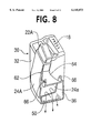
- FIG. 8 is a perspective of the inside of the buckle in the same state as FIG. 7.
- FIG. 9 is a vertical cross sectional view of the buckle of the third embodiment of the present invention.
- FIG. 10 is a perspective view showing the duct and plug of the third embodiment.
- FIG. 11 is a cross sectional view of the primary part of the tongue of the third embodiment in the state fastened to the buckle.
- FIGS. 12(a) and 12(b) show a prior air belt.
- FIG. 1 is a perspective view of the tongue and buckle of the air belt device of the first embodiment of the present invention.
- FIG. 2 is a partially sectioned perspective view of the buckle.
- FIG. 3 is a cross sectional view along the line III--III of FIG. 1 and FIG. 2.
- FIG. 4 is a cross sectional view of the buckle when gas is released.
- FIG. 5 shows the perspective views of the plug and duct, wherein FIG. 5 (a) shows the plug with the upper end closed and FIG. 5 (b) shows the plug with the upper end opened.
- the tongue 12 is fastened to the buckle 10 of this air belt device.
- the buckle 10 is provided with a tongue plate insertion slit 16 into which the tongue plate 14 of the tongue 12 is inserted, a latch mechanism (not shown) in the depth of the tongue plate insertion slit 16, and a press button 18 to reset the latch of the latch mechanism.
- the buckle 10 comprises a plug 22 onto which the socket 20 of the tongue 12 is inserted from the forward end side, a duct 24 into which the lower end of the plug 22 is inserted, an inflator 26 has a gas generator to supply gas into the duct 24, and a casing 30 which houses the plug 22, duct 24 and inflator 26.
- the casing 30 is made in one body with a duct housing 32 which contains the plug 22 and duct 24 and an inflator housing 34 which contains the inflator 26.
- An opening 36 is provided between these housings 32 and 34.
- An entrance 24a of the duct 24 is fit to this opening 36.
- a socket insertion slit 38 is provided in the upper end of the duct housing 32.
- the upper end of the plug 22 projects a little over the socket insertion slit 38.
- the socket 20 is inserted between the internal circumference of the socket insertion slit 38 and the periphery of the plug 22.
- the lower end of the plug 22 is fit over an exit 24b of the duct 24 and is movable in the direction of separating away from the duct 24 by the pressure of the gas from the inflator 26.
- the plug 22 has a projection 40 which hangs over the outside of the duct 24.
- a knob 42 on the outside of the duct 24 fits in a guide hole (elongate hole) 44 of the projection 40, and when the plug 22 moves in the direction of separating away from the duct 24, the movement of the plug 22 is guided by the engagement of the knob 42 with the guide hole 44.
- the upper end of the plug 22 is closed but has a tear line 46 buried under the surface.
- a gas ejection port 48 is opened as shown in FIG. 5 (b).
- a release port 50 is provided at the bottom of the duct housing 32 of the casing 30.
- a bracket 52 is provided projecting downward from the inflator housing 34.
- the bracket 52 has a bolt hole 54.
- a bolt (not shown) is inserted into the bolt hole 54 to fasten the buckle 10 to the vehicle body member (not shown).
- a bag-like shoulder belt 56 is connected to the tongue 12.
- the inside of the shoulder belt 56 leads to the inside of the socket 20.
- the wrap belt 58 is also fastened to the tongue 12.
- a tongue plate 14 is inserted into the tongue plate insertion slit 16 to fasten the tongue 12 to the buckle 10.
- the socket 20 is inserted into the socket insertion slit 38 and at the same time it is fit over the plug 22.
- the tongue plate 14 is inserted deeply enough into the tongue plate insertion slit 16, the latch claw of the latch mechanism fits into the latch hole 14a of the tongue plate 14, and the tongue 12 can not separate from the buckle 10.
- a press button 18 is depressed, the latch claw comes off from the latch hole 14a, the tongue plate 14 is pushed upward by the spring force (not shown) and the tongue 12 separates from the buckle 10.
- the gas ejected from the gas ejection port 26a of the inflator rushes into the duct 24 through the duct entrance 24a that is fit to the opening 36 and applies a large pressure to the upper end of the plug 22.
- the plug 22 can not move upward, the tear line 46 is broken by the gas pressure and the gas ejection port 48 is opened.
- the gas from the inflator 26 is supplied into the bag-like shoulder belt 56 passing through the gas ejection port 48 and socket 20, whereby the bag-like shoulder belt 56 is inflated.
- the inflator 26 If the inflator 26 is activated accidentally and ejects gas in the state the tongue 12 is not fastened to the buckle 10, the gas from the gas ejection port 26a rushes likewise into the duct 24 and applies a large pressure to the upper end of the plug 22.
- the plug 22 moves upward as shown in FIG. 4 and a clearance is made between the plug 22 and the upper end of the duct 24.
- the gas flowing out of the gas exit 24b of the duct 24 is fed between the duct 24 and the casing 30 through this clearance and is released downward from the release port 50. Since the gas from the inflator 26 is released downward from the release port 50, this prevents a driver from being exposed to a blast of gas.
- FIG. 6 is a vertical cross section of the air belt device of the second embodiment of the present invention.
- FIG. 7 shows the mechanism when the inflator 26 of the buckle malfunctions.
- FIG. 8 shows a perspective of the inside of the buckle.
- the duct 24A and plug 22A are made in one body.
- the duct 24A has an entrance upper edge 64 which is connected to the duct 24A so as to be rotatable relatively to the duct 24A with a hinge pin 62.
- the entrance upper edge 64 has a bracket 66 which is fixed to the casing 30 with a rivet 68.
- the entrance 24a of the duct 24A is fit removable from the opening 36 of the casing 30.
- the tongue 12 (not shown in FIG. 6 and FIG. 7) can be fastened to the buckle 10A that is constructed as above described, and when the press button is depressed, the linkage is released. If the inflator 26 is activated while the tongue 12 is fastened to the buckle, the tear line 46 breaks and the inflator 26 supplies gas into the bag-like shoulder belt 56.
- the socket 20 With the socket 20 inserted into the socket insertion slit 38, the socket 20 contacts the internal wall of the socket insertion slit 38 and prevents the duct 24A from inclining so that all the gas from the inflator 26 is supplied to the bag-like shoulder belt 56 through the duct 24A.
- the duct 24A rotates centering around the pivot hinge pin 62 as shown in FIG. 7 and FIG. 8, whereby the entrance 24a of the duct 24A separates from the opening 36, the opening 36 is directly led to the release port 50, and the gas from the inflator 26 is released downward from the release port 50.
- FIG. 9 is a vertical cross sectional view of the buckle of the air belt device of the third embodiment of the present invention.
- FIG. 10 is perspective view of the duct and plug used in this buckle.
- FIG. 11 is a cross sectional view of the tongue and buckle fastened to each other.
- the duct 24B and plug 22B are constructed in one body and a gas discharge port 72 is provided on the side of the plug 22B.
- the other configuration is similar to the first embodiment, and the same symbols correspond to the same parts. Detailed description is omitted.
- the socket 20 fits over the plug 22B and closes the gas discharge port 72 in FIG. 11.
- the inflator 26 is activated in this state, the pressure of gas higher than a specified value is applied to the upper end of the plug 22B, the tear line 46 beaks and the gas is supplied to the bag-like shoulder belt 56.
- the inflator 26 is activated in the state the tongue 12 is separated from the buckle 10B, as the gas discharge port 72 is open, the gas is discharged from the gas discharge port 72, fed between the casing 30 and duct 24B and released downward from the release port 50.
- the release port 50 is faced down to release the gas from the inflator downward from the casing 30, but the release port can be in the side of the casing to release the gas sideways. It is also obvious that the release port can be tilted down to release the gas obliquely downward.
- the gas generator when the gas generator is activated in the state the tongue is not fastened to the buckle, the gas is released downward or sideways.
Landscapes
- Engineering & Computer Science (AREA)
- Mechanical Engineering (AREA)
- Physics & Mathematics (AREA)
- Fluid Mechanics (AREA)
- Air Bags (AREA)
- Automotive Seat Belt Assembly (AREA)
Applications Claiming Priority (2)
| Application Number | Priority Date | Filing Date | Title |
|---|---|---|---|
| JP23690797A JP3465546B2 (ja) | 1997-09-02 | 1997-09-02 | エアベルト装置 |
| JP9-236907 | 1997-09-02 |
Publications (1)
| Publication Number | Publication Date |
|---|---|
| US6145873A true US6145873A (en) | 2000-11-14 |
Family
ID=17007529
Family Applications (1)
| Application Number | Title | Priority Date | Filing Date |
|---|---|---|---|
| US09/145,273 Expired - Fee Related US6145873A (en) | 1997-09-02 | 1998-09-02 | Air belt device |
Country Status (4)
| Country | Link |
|---|---|
| US (1) | US6145873A (fr) |
| EP (1) | EP0901941B1 (fr) |
| JP (1) | JP3465546B2 (fr) |
| DE (1) | DE69810043T2 (fr) |
Cited By (6)
| Publication number | Priority date | Publication date | Assignee | Title |
|---|---|---|---|---|
| US6406058B1 (en) * | 1999-11-18 | 2002-06-18 | Universal Propulsion Co., Inc. | Inflatable safety restraint system |
| US20030159613A1 (en) * | 2002-02-22 | 2003-08-28 | Quioc Eduardo L. | Airbelt inflator |
| WO2003072381A2 (fr) | 2002-02-26 | 2003-09-04 | Automotive Systems Laboratory, Inc. | Appareil de gonflage d'une ceinture a air |
| WO2004094188A2 (fr) | 2003-04-17 | 2004-11-04 | Automotive Systems Laboratory, Inc. | Systeme de gonflage pour chocs lateraux et pour ceinture de securite |
| US6973634B1 (en) * | 2002-01-22 | 2005-12-06 | Cadence Design Systems, Inc. | IC layouts with at least one layer that has more than one preferred interconnect direction, and method and apparatus for generating such a layout |
| US20060290111A1 (en) * | 2005-06-28 | 2006-12-28 | Takata Corporation | Occupant restraint apparatus |
Families Citing this family (5)
| Publication number | Priority date | Publication date | Assignee | Title |
|---|---|---|---|---|
| EP0963885B1 (fr) * | 1998-06-09 | 2003-08-13 | Takata Corporation | Dispositif de ceinture de sécurité gonflable |
| US20020105175A1 (en) * | 1999-06-09 | 2002-08-08 | Donald J. Lewis | An inflatable seat belt anchorage and inflating system |
| DE19946912A1 (de) * | 1999-09-30 | 2001-04-05 | Bayerische Motoren Werke Ag | Aufblasbarer Sicherheitsgurt |
| JP4953750B2 (ja) * | 2006-10-11 | 2012-06-13 | 日本プラスト株式会社 | エアバッグモジュール |
| JP4946444B2 (ja) * | 2007-01-04 | 2012-06-06 | 豊田合成株式会社 | 乗員保護装置 |
Citations (7)
| Publication number | Priority date | Publication date | Assignee | Title |
|---|---|---|---|---|
| US3791670A (en) * | 1972-09-21 | 1974-02-12 | Allied Chem | Band buckle for use with inflatable seat belts |
| US3801156A (en) * | 1971-11-15 | 1974-04-02 | H Granig | Safety-belt |
| US3874694A (en) * | 1972-12-11 | 1975-04-01 | Allied Chem | Unitary tongue inflator for inflatable restraint |
| US3929348A (en) * | 1974-02-13 | 1975-12-30 | Allied Chem | Tongue for inflataband |
| FR2681558A1 (fr) * | 1991-09-24 | 1993-03-26 | Takata Corp | Ceinture de securite gonflable. |
| GB2269791A (en) * | 1992-08-06 | 1994-02-23 | Takata Corp | Inflatable seat belts for vehicles. |
| US6019388A (en) * | 1997-09-30 | 2000-02-01 | Honda Giken Kogyo Kabushiki Kaisha | Occupant protecting device |
Family Cites Families (2)
| Publication number | Priority date | Publication date | Assignee | Title |
|---|---|---|---|---|
| JP3064507B2 (ja) | 1991-07-04 | 2000-07-12 | 市光工業株式会社 | マークの表示方法 |
| US5288104A (en) | 1992-11-09 | 1994-02-22 | Johnny Chen | Buffering safe device in vehicles |
-
1997
- 1997-09-02 JP JP23690797A patent/JP3465546B2/ja not_active Expired - Fee Related
-
1998
- 1998-09-02 EP EP98116543A patent/EP0901941B1/fr not_active Expired - Lifetime
- 1998-09-02 DE DE69810043T patent/DE69810043T2/de not_active Expired - Fee Related
- 1998-09-02 US US09/145,273 patent/US6145873A/en not_active Expired - Fee Related
Patent Citations (8)
| Publication number | Priority date | Publication date | Assignee | Title |
|---|---|---|---|---|
| US3801156A (en) * | 1971-11-15 | 1974-04-02 | H Granig | Safety-belt |
| US3791670A (en) * | 1972-09-21 | 1974-02-12 | Allied Chem | Band buckle for use with inflatable seat belts |
| US3874694A (en) * | 1972-12-11 | 1975-04-01 | Allied Chem | Unitary tongue inflator for inflatable restraint |
| US3929348A (en) * | 1974-02-13 | 1975-12-30 | Allied Chem | Tongue for inflataband |
| FR2681558A1 (fr) * | 1991-09-24 | 1993-03-26 | Takata Corp | Ceinture de securite gonflable. |
| JPH0585301A (ja) * | 1991-09-24 | 1993-04-06 | Takata Kk | インフレータブルシートベルト装置 |
| GB2269791A (en) * | 1992-08-06 | 1994-02-23 | Takata Corp | Inflatable seat belts for vehicles. |
| US6019388A (en) * | 1997-09-30 | 2000-02-01 | Honda Giken Kogyo Kabushiki Kaisha | Occupant protecting device |
Cited By (12)
| Publication number | Priority date | Publication date | Assignee | Title |
|---|---|---|---|---|
| US6406058B1 (en) * | 1999-11-18 | 2002-06-18 | Universal Propulsion Co., Inc. | Inflatable safety restraint system |
| US6973634B1 (en) * | 2002-01-22 | 2005-12-06 | Cadence Design Systems, Inc. | IC layouts with at least one layer that has more than one preferred interconnect direction, and method and apparatus for generating such a layout |
| US20030159613A1 (en) * | 2002-02-22 | 2003-08-28 | Quioc Eduardo L. | Airbelt inflator |
| US6851373B2 (en) | 2002-02-22 | 2005-02-08 | Automotive Systems Laboratory, Inc. | Airbelt inflator |
| WO2003072381A2 (fr) | 2002-02-26 | 2003-09-04 | Automotive Systems Laboratory, Inc. | Appareil de gonflage d'une ceinture a air |
| US6871873B2 (en) | 2002-02-26 | 2005-03-29 | Automotive Systems Laboratory, Inc. | Airbelt inflator |
| WO2004094188A2 (fr) | 2003-04-17 | 2004-11-04 | Automotive Systems Laboratory, Inc. | Systeme de gonflage pour chocs lateraux et pour ceinture de securite |
| US20040256847A1 (en) * | 2003-04-17 | 2004-12-23 | Quioc Eduardo L. | Belt and side impact inflator |
| WO2004094188A3 (fr) * | 2003-04-17 | 2006-07-27 | Automotive Systems Lab | Systeme de gonflage pour chocs lateraux et pour ceinture de securite |
| US7506891B2 (en) * | 2003-04-17 | 2009-03-24 | Automotive Systems Laboratory Inc. | Belt and side impact inflator |
| US20060290111A1 (en) * | 2005-06-28 | 2006-12-28 | Takata Corporation | Occupant restraint apparatus |
| US7516979B2 (en) * | 2005-06-28 | 2009-04-14 | Takata Corporation | Occupant restraint apparatus |
Also Published As
| Publication number | Publication date |
|---|---|
| EP0901941B1 (fr) | 2002-12-11 |
| JPH1178779A (ja) | 1999-03-23 |
| EP0901941A3 (fr) | 1999-10-20 |
| DE69810043D1 (de) | 2003-01-23 |
| JP3465546B2 (ja) | 2003-11-10 |
| DE69810043T2 (de) | 2003-10-09 |
| EP0901941A2 (fr) | 1999-03-17 |
Similar Documents
| Publication | Publication Date | Title |
|---|---|---|
| JP3433654B2 (ja) | エアベルト装置 | |
| US6145873A (en) | Air belt device | |
| KR100360205B1 (ko) | 자동차의 측면충돌용 에어백장치 | |
| US5445411A (en) | Inflatable seat belt apparatus | |
| US5346250A (en) | Inflatable seat belt unit | |
| US6019388A (en) | Occupant protecting device | |
| US6471243B1 (en) | Inflation mechanism for inflatable seat belt | |
| EP0963885B1 (fr) | Dispositif de ceinture de sécurité gonflable | |
| US6168196B1 (en) | Tongue for an inflatable belt and inflatable belt device | |
| JP2001130365A (ja) | 乗員保護装置 | |
| US5833311A (en) | Add-on child seat | |
| EP0901943A2 (fr) | Dispositif de ceinture de sécurité gonflable | |
| US6293626B1 (en) | Tongue for an inflatable belt and an inflatable belt device | |
| KR20100026356A (ko) | 승객의 상해를 저감하는 조수석 에어백 모듈 | |
| JP3724195B2 (ja) | エアベルト装置 | |
| JP3724194B2 (ja) | エアベルト装置 | |
| JP3945731B2 (ja) | 乗員保護装置 | |
| KR930009204B1 (ko) | 자동차용 공기 튜브 안전장치 | |
| CN101107152A (zh) | 具有可控制系带的安全气囊模块 | |
| JP2001270418A (ja) | エアベルト装置及びそれ用のバックル | |
| JP2000016227A (ja) | エアバッグの起動装置 | |
| JPH06156179A (ja) | エアバッグの内圧調整装置 | |
| JPH1128996A (ja) | 乗員保護装置 | |
| KR19980064017U (ko) | 조수석 에어 백 | |
| JP2001097158A (ja) | エアバッグ装置 |
Legal Events
| Date | Code | Title | Description |
|---|---|---|---|
| AS | Assignment |
Owner name: TAKATA CORPORATION, JAPAN Free format text: ASSIGNMENT OF ASSIGNORS INTEREST;ASSIGNOR:SUYAMA, YOJI;REEL/FRAME:009601/0548 Effective date: 19981104 |
|
| AS | Assignment |
Owner name: TAKATA CORPORATION, JAPAN Free format text: CORRECTIVE ASSIGNMENT TO CORRECT THE NAME OF THE ASSIGNOR, FILED ON 11-17-98, RECORDED AT REEL 9601 FRAME 0548;ASSIGNOR:TAKEUCHI, HIROYUKI;REEL/FRAME:010784/0860 Effective date: 19981104 |
|
| FEPP | Fee payment procedure |
Free format text: PAYOR NUMBER ASSIGNED (ORIGINAL EVENT CODE: ASPN); ENTITY STATUS OF PATENT OWNER: LARGE ENTITY |
|
| FPAY | Fee payment |
Year of fee payment: 4 |
|
| FPAY | Fee payment |
Year of fee payment: 8 |
|
| REMI | Maintenance fee reminder mailed | ||
| LAPS | Lapse for failure to pay maintenance fees | ||
| STCH | Information on status: patent discontinuation |
Free format text: PATENT EXPIRED DUE TO NONPAYMENT OF MAINTENANCE FEES UNDER 37 CFR 1.362 |
|
| FP | Lapsed due to failure to pay maintenance fee |
Effective date: 20121114 |