US6138487A - Roll for influencing flatness - Google Patents
Roll for influencing flatness Download PDFInfo
- Publication number
- US6138487A US6138487A US09/244,649 US24464999A US6138487A US 6138487 A US6138487 A US 6138487A US 24464999 A US24464999 A US 24464999A US 6138487 A US6138487 A US 6138487A
- Authority
- US
- United States
- Prior art keywords
- roll
- rotation
- load application
- shell
- application surface
- Prior art date
- Legal status (The legal status is an assumption and is not a legal conclusion. Google has not performed a legal analysis and makes no representation as to the accuracy of the status listed.)
- Expired - Fee Related
Links
- 238000005096 rolling process Methods 0.000 claims abstract description 24
- 238000005452 bending Methods 0.000 claims abstract description 12
- 239000000463 material Substances 0.000 claims abstract description 5
- 230000007423 decrease Effects 0.000 claims description 3
- 238000010586 diagram Methods 0.000 description 6
- 239000002184 metal Substances 0.000 description 6
- 238000000034 method Methods 0.000 description 4
- 238000009826 distribution Methods 0.000 description 3
- 239000003921 oil Substances 0.000 description 3
- 230000006978 adaptation Effects 0.000 description 1
- 230000015572 biosynthetic process Effects 0.000 description 1
- 238000011109 contamination Methods 0.000 description 1
- 238000005520 cutting process Methods 0.000 description 1
- 238000006073 displacement reaction Methods 0.000 description 1
- 230000000694 effects Effects 0.000 description 1
- 239000000839 emulsion Substances 0.000 description 1
- 230000002349 favourable effect Effects 0.000 description 1
- -1 for example Substances 0.000 description 1
- 239000010720 hydraulic oil Substances 0.000 description 1
- 230000007246 mechanism Effects 0.000 description 1
- 238000003801 milling Methods 0.000 description 1
- 238000003825 pressing Methods 0.000 description 1
- 238000013000 roll bending Methods 0.000 description 1
- 239000010731 rolling oil Substances 0.000 description 1
- 239000007787 solid Substances 0.000 description 1
- 238000001228 spectrum Methods 0.000 description 1
Images


Classifications
-
- B—PERFORMING OPERATIONS; TRANSPORTING
- B21—MECHANICAL METAL-WORKING WITHOUT ESSENTIALLY REMOVING MATERIAL; PUNCHING METAL
- B21B—ROLLING OF METAL
- B21B27/00—Rolls, roll alloys or roll fabrication; Lubricating, cooling or heating rolls while in use
- B21B27/02—Shape or construction of rolls
- B21B27/03—Sleeved rolls
- B21B27/05—Sleeved rolls with deflectable sleeves
-
- B—PERFORMING OPERATIONS; TRANSPORTING
- B21—MECHANICAL METAL-WORKING WITHOUT ESSENTIALLY REMOVING MATERIAL; PUNCHING METAL
- B21B—ROLLING OF METAL
- B21B13/00—Metal-rolling stands, i.e. an assembly composed of a stand frame, rolls, and accessories
- B21B13/02—Metal-rolling stands, i.e. an assembly composed of a stand frame, rolls, and accessories with axes of rolls arranged horizontally
- B21B2013/025—Quarto, four-high stands
Definitions
- the present invention relates to a roll, particularly a back-up roll, for rolling flat material.
- the roll is composed of a rotating roll shell and means arranged within the roll shell for influencing the bending stiffness of the roll shell.
- the rolling forces are applied by work rolls which rest on the flat material, for example, metal strip.
- the rolling forces must be distributed as uniformly as possible over the entire length of the roll, i.e., the line of contact between the circumference of the roll and the strip should be a straight line.
- the rolling stock interferes with obtaining the straight line, and this interference results in a zone of the roll to which a greater load is applied and in a crown of the roll.
- CVC-method continuous variable crown method
- German patent application 196 37 584.3 proposes to compensate bending of the shell-type rolls by means of friction bearings within the rolls.
- These friction bearings are, for example, spherical friction bearings mounted on a support axis or shaft, wherein the friction bearings can be arranged so as to be adjustable with respect to their spacing and securable in their position.
- the friction bearings are constructed as oil film bearings.
- the rolls of this type have the disadvantage that the compensation zone between the bearing shells in the interior of the roll and the shell of the back-up roll is predetermined by the respective bearing width, number of bearings and arrangement of bearings. Consequently, this system cannot operate without additional adjusting means for influencing the flatness.
- U.S. Pat. No. 4,407,151 also proposes the mounting of support means in the hollow interior of a shell-type roll as a possibility for influencing the bending stiffness of the roll.
- support discs mounted on a shaft are to be arranged at selected points along the length of the roll. The discs themselves can be displaced along the hollow interior of the roll by applying pressure.
- the roll shell receives a shaft with clearance fit or close fit. The adjustment to the flat material to be processed is achieved by displacing the respective shafts of two back-up rolls.
- the means for influencing the bending stiffness of the roll shell is a friction bearing in the form of a body or solid of or generated by rotation.
- the body of rotation can be adjusted by rotating the body.
- the body of rotation is shaped in such a way that the load application surface thereof corresponding to the zone of the roll shell to which load is applied is part of the circumferential surface of a rotation-symmetrical body and the edge of this circumferential surface is shaped in such a way that along the circumference of the body of rotation the width and/or position of the load application surface vary.
- the present invention proposes a roll which is composed of a rotating roll shell and a friction bearing arranged within the roll shell in the form of a body of rotation for influencing the bending stiffness of the roll shell.
- This body of rotation constitutes a counter-force to the load application zone of the roll shell produced by the rolling stock.
- the counter-force counteracts the crown of the roll or the work rolls.
- the roll according to the present invention makes possible a quick and optimum adaptation to the changes of the rolling conditions.
- the selection of the rotation-symmetrical body and of the shape of the edge of the load application surface are the result of computations and can be determined in dependence on the strip widths to be rolled and the necessary rolling force spectrum.
- the load application surface is part of the circumferential surface of a cylinder.
- the surface may also be curved, for example, following the contour of an ellipsoid or paraboloid.
- the load application surface has a certain pattern.
- the body of rotation already manufactured in an adapted manner can be further adapted simply and quickly to varying metal strip widths and, thus, to loading forces which act on the roll shell by rotating the body of rotation.
- the load application surface in the contact zone with other rolls or the rolling stock can be rotated into that position in which the load application surface of the body of rotation corresponds approximately to the strip width to be processed and the resulting load application zone in the roll shell.
- the body of rotation has in the area of its load application surface a cutout whose edge and contour can be configured as desired. Also, several cutouts of this type may be provided. The configuration of the edge of the cutout and the contour thereof are also specifically computed, as is the case with respect to the edge of the circumferential surface of the body of rotation. These cutouts forming load relieving areas are advantageous when there is a simultaneous occurrence of middle waves and border waves or of quarter waves.
- the body of rotation has edge areas which are located adjacent to the middle load application surface. These edge areas may also have any selected shape. In accordance with an advantageous feature, the conference of the edge areas decreases toward the ends of the body of rotation, for example, the edge areas are truncated cone-shaped. However, the shape of the edge areas does not absolutely have to be rotation-symmetrical.
- a single body of rotation is received in the roll shell. It is also conceivable that several bodies of rotation arranged next to one another are mounted within the hollow interior of the roll, wherein these bodies of rotation can be adjusted to the rolling conditions either individually or together by rotating them.
- a body of rotation which is composed of several portions which engage fittingly into each other or can be moved away from each other.
- the roll proposed in accordance with the present invention is advantageously used as a back-up roll.
- four-high stands or other multiple roll stands are conceivable in this connection.
- FIG. 1 is a schematic perspective view of a body of rotation in accordance with the present invention
- FIG. 2 is a schematic perspective view, partially in section, showing the upper half of a four-high set of rolls with a back-up roll composed of a roll shell and the body of rotation shown in FIG. 1;
- FIG. 3 is a diagram showing the roll gap profile over the strip width during the rolling procedure using the back-up roll arrangement shown in FIG. 2;
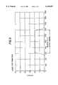
- FIG. 4 is a diagram showing the roll gap profile over the strip width during the rolling procedure using a conventional back-up roll arrangement
- FIG. 5 is a diagram showing the load distribution between the body of rotation and the roll shell over the strip width.
- FIG. 6 is a perspective view showing a four-high roll stand.
- FIG. 1 of the drawing shows an embodiment of the body of rotation 1 according to the present invention
- FIG. 2 schematically shows how the body of rotation 1 is mounted in the back-up roll of a four-high roll stand.
- the body of rotation 1 has a middle load application surface 2 which constitutes part of the circumferential surface of a rotation-symmetrical body.
- the specific circumferential surface is that of a cylinder.
- the edge of the circumferential surface is denoted by 4.
- the edge configuration is a consequence of a product program and is individually computed.
- the edges 4 of the developed circumferential surface each form a sinusoid. This has the consequence that the distance of the edges between each other increases over the circumference of the body of rotation as indicated by distance a, and then once again decreases as indicated by distance b.
- the body of rotation 1 has edge areas 3 connected to the load application surface 2.
- these edge areas 3 are intersected obliquely at the cylindrical middle portion and are truncated cone-shaped.
- the cylinder and the obliquely intersected edge areas 3 have the same axis of rotation.
- a cutout 10 indicated by broken lines.
- the cutout can be produced by milling cutting of the body of rotation.
- the cutout has a drop-shaped edge configuration 11.
- the contour of the cutout 10 in the interior of the body of rotation is not illustrated; it can have any configuration.
- FIG. 2 of the drawing schematically shows the body of rotation 1 according to the present invention forming a friction bearing in a roll shell 5 which is shown partially cut away.
- the roll shell 5 rotates on a work roll 6, while the body of rotation is locked at a predetermined angle of rotation.
- the work roll 6 rests on the metal strip 8 to be rolled.
- the loads produced by the rolling stock have a disadvantageous effect on the crown of the work roll 6 and, thus, also on the flatness of the metal strip 8.
- the load application zone produced by the rolling stock and the outward bulging of the work roll 6 are subjected to a counter-force produced by the back-up roll, particularly by the body of rotation 1. By turning the body of rotation 1, it is adjusted and then secured in such a way that the optimum load application surface 2 of the body of rotation 1 for the occurring forces is used together with the load application zone 9.
- FIG. 3 shows the roll gap profile during rolling of a metal strip having a width of 800 mm in a four-high stand [2,000 mm ⁇ 420 mm (work roll) 1,500 mm (back-up roll)].
- a back-up roll operating in accordance with the above-described principle was used.
- the width of the load application surface was selected narrower by 30 mm than the strip width.
- FIG. 4 shows by way of comparison the roll gap profiles during the rolling process with a conventional back-up roll arrangement, wherein the crown influencing means is optimized for a strip having a width of 1,200 mm. It is apparent that the roll gap profiles are less box-shaped and, thus, less favorable.
- the diagram of FIG. 5 shows the load distribution between the body of rotation and the roll shell over the strip width, which in the illustrated embodiment is 800 mm.
- the adjusted load application surface width is 770 mm.
- a uniform load pattern occurs between the load application surface and the rotating roll shell.
- This uniform load pattern is equivalent to an almost constant oil film thickness in the friction bearing and prevents undesired contacts with the friction bearing surfaces.
- the shape of the middle portion of the body of rotation necessary for this purpose corresponded to a conventional crown of 0.4 mm diameter difference along the roll body (in relation to 2,000 mm).
- the middle portion of the body of rotation, i.e., the load application surface is parabolically drum-shaped.
- FIG. 6 shows a roll stand with two work rolls 6 and two back-up rolls 5.
Landscapes
- Engineering & Computer Science (AREA)
- Mechanical Engineering (AREA)
- Physics & Mathematics (AREA)
- Geometry (AREA)
- Reduction Rolling/Reduction Stand/Operation Of Reduction Machine (AREA)
- Rolls And Other Rotary Bodies (AREA)
- Paper (AREA)
- Spinning Or Twisting Of Yarns (AREA)
- Valve-Gear Or Valve Arrangements (AREA)
Applications Claiming Priority (2)
| Application Number | Priority Date | Filing Date | Title |
|---|---|---|---|
| DE19807115 | 1998-02-20 | ||
| DE19807115A DE19807115C1 (de) | 1998-02-20 | 1998-02-20 | Walze |
Publications (1)
| Publication Number | Publication Date |
|---|---|
| US6138487A true US6138487A (en) | 2000-10-31 |
Family
ID=7858375
Family Applications (1)
| Application Number | Title | Priority Date | Filing Date |
|---|---|---|---|
| US09/244,649 Expired - Fee Related US6138487A (en) | 1998-02-20 | 1999-02-04 | Roll for influencing flatness |
Country Status (11)
| Country | Link |
|---|---|
| US (1) | US6138487A (fr) |
| EP (1) | EP0937515B1 (fr) |
| JP (1) | JP4778596B2 (fr) |
| KR (1) | KR100581188B1 (fr) |
| CN (1) | CN1113709C (fr) |
| AT (1) | ATE237412T1 (fr) |
| BR (1) | BR9917373A (fr) |
| CA (1) | CA2262261C (fr) |
| DE (2) | DE19807115C1 (fr) |
| RU (1) | RU2220797C2 (fr) |
| TW (1) | TW396065B (fr) |
Cited By (4)
| Publication number | Priority date | Publication date | Assignee | Title |
|---|---|---|---|---|
| US20100032126A1 (en) * | 2008-08-05 | 2010-02-11 | Nucor Corporation | Method for casting metal strip with dynamic crown control |
| US20100032128A1 (en) * | 2008-08-05 | 2010-02-11 | Nucor Corporation | Method for casting metal strip with dynamic crown control |
| US20120000263A1 (en) * | 2009-04-17 | 2012-01-05 | Sms Siemag Aktiengesellschaft | Method for providing at least one work roll for rolling rolling stock |
| US8505611B2 (en) | 2011-06-10 | 2013-08-13 | Castrip, Llc | Twin roll continuous caster |
Families Citing this family (4)
| Publication number | Priority date | Publication date | Assignee | Title |
|---|---|---|---|---|
| DE10039000A1 (de) * | 2000-08-10 | 2002-02-21 | Sms Demag Ag | Hohlmantelwalze |
| JP3747786B2 (ja) | 2001-02-05 | 2006-02-22 | 株式会社日立製作所 | 板材用圧延機の圧延方法及び板材用圧延設備 |
| DE102006002773A1 (de) | 2005-07-07 | 2007-01-18 | Sms Demag Ag | Stützwalze für ein Walzwerk |
| CN102310082B (zh) * | 2011-06-07 | 2015-12-02 | 东莞新能源科技有限公司 | 压辊 |
Citations (8)
| Publication number | Priority date | Publication date | Assignee | Title |
|---|---|---|---|---|
| JPS57127507A (en) * | 1981-01-30 | 1982-08-07 | Ishikawajima Harima Heavy Ind Co Ltd | Rolling mill |
| GB2094687A (en) * | 1981-03-12 | 1982-09-22 | Davy Loewy Ltd | Rolling mill rolls |
| US4407151A (en) * | 1980-07-17 | 1983-10-04 | Davey-Loewy Limited | Rolling mill |
| US4651547A (en) * | 1983-10-14 | 1987-03-24 | Clecim | Process for adjusting the thickness and profile of a flat product in the course of rolling |
| US4658621A (en) * | 1983-12-22 | 1987-04-21 | Sulzer-Escher Wyss Ag | Rolling apparatus |
| US4722212A (en) * | 1985-11-06 | 1988-02-02 | United Engineering Rolling Mills, Inc. | Self-compensating roll |
| US5007152A (en) * | 1989-10-27 | 1991-04-16 | Sumitomo Metal Industries, Ltd. | Variable-crown roll |
| DE19637584A1 (de) * | 1996-09-14 | 1998-03-19 | Schloemann Siemag Ag | Lagerung für biegesteife Mantelwalzen auf einer Tragachse oder Tragwelle |
Family Cites Families (5)
| Publication number | Priority date | Publication date | Assignee | Title |
|---|---|---|---|---|
| JPS5744404A (en) * | 1980-07-17 | 1982-03-12 | Davy Loewy Ltd | Rolling mill |
| JPS57159206A (en) * | 1981-03-12 | 1982-10-01 | Davy Loewy Ltd | Roll for rolling mill |
| JPS6158904U (fr) * | 1984-09-18 | 1986-04-21 | ||
| JPS61226105A (ja) * | 1985-03-30 | 1986-10-08 | Nisshin Steel Co Ltd | 多段圧延機のロ−ル |
| GB2238597B (en) * | 1989-09-15 | 1993-03-31 | Davy Mckee | Rolling mill roll |
-
1998
- 1998-02-20 DE DE19807115A patent/DE19807115C1/de not_active Expired - Fee Related
-
1999
- 1999-02-04 US US09/244,649 patent/US6138487A/en not_active Expired - Fee Related
- 1999-02-09 TW TW088101949A patent/TW396065B/zh active
- 1999-02-11 EP EP99102577A patent/EP0937515B1/fr not_active Expired - Lifetime
- 1999-02-11 DE DE59905024T patent/DE59905024D1/de not_active Expired - Lifetime
- 1999-02-11 AT AT99102577T patent/ATE237412T1/de active
- 1999-02-15 CA CA002262261A patent/CA2262261C/fr not_active Expired - Fee Related
- 1999-02-18 BR BR9917373-5A patent/BR9917373A/pt not_active IP Right Cessation
- 1999-02-19 JP JP04198299A patent/JP4778596B2/ja not_active Expired - Fee Related
- 1999-02-19 RU RU99103331/02A patent/RU2220797C2/ru not_active IP Right Cessation
- 1999-02-19 KR KR1019990005478A patent/KR100581188B1/ko not_active IP Right Cessation
- 1999-02-20 CN CN99102232A patent/CN1113709C/zh not_active Expired - Fee Related
Patent Citations (8)
| Publication number | Priority date | Publication date | Assignee | Title |
|---|---|---|---|---|
| US4407151A (en) * | 1980-07-17 | 1983-10-04 | Davey-Loewy Limited | Rolling mill |
| JPS57127507A (en) * | 1981-01-30 | 1982-08-07 | Ishikawajima Harima Heavy Ind Co Ltd | Rolling mill |
| GB2094687A (en) * | 1981-03-12 | 1982-09-22 | Davy Loewy Ltd | Rolling mill rolls |
| US4651547A (en) * | 1983-10-14 | 1987-03-24 | Clecim | Process for adjusting the thickness and profile of a flat product in the course of rolling |
| US4658621A (en) * | 1983-12-22 | 1987-04-21 | Sulzer-Escher Wyss Ag | Rolling apparatus |
| US4722212A (en) * | 1985-11-06 | 1988-02-02 | United Engineering Rolling Mills, Inc. | Self-compensating roll |
| US5007152A (en) * | 1989-10-27 | 1991-04-16 | Sumitomo Metal Industries, Ltd. | Variable-crown roll |
| DE19637584A1 (de) * | 1996-09-14 | 1998-03-19 | Schloemann Siemag Ag | Lagerung für biegesteife Mantelwalzen auf einer Tragachse oder Tragwelle |
Non-Patent Citations (2)
| Title |
|---|
| Patent Abstracts of Japan, vol. 006, No. 224 (M 170), Nov. 9, 1982 & JP 57 127507 A (Ishikawajima Harima Jukogyo KK) Aug. 7, 1982. * |
| Patent Abstracts of Japan, vol. 006, No. 224 (M-170), Nov. 9, 1982 & JP 57 127507 A (Ishikawajima Harima Jukogyo KK) Aug. 7, 1982. |
Cited By (6)
| Publication number | Priority date | Publication date | Assignee | Title |
|---|---|---|---|---|
| US20100032126A1 (en) * | 2008-08-05 | 2010-02-11 | Nucor Corporation | Method for casting metal strip with dynamic crown control |
| US20100032128A1 (en) * | 2008-08-05 | 2010-02-11 | Nucor Corporation | Method for casting metal strip with dynamic crown control |
| US8607848B2 (en) | 2008-08-05 | 2013-12-17 | Nucor Corporation | Method for casting metal strip with dynamic crown control |
| US8607847B2 (en) | 2008-08-05 | 2013-12-17 | Nucor Corporation | Method for casting metal strip with dynamic crown control |
| US20120000263A1 (en) * | 2009-04-17 | 2012-01-05 | Sms Siemag Aktiengesellschaft | Method for providing at least one work roll for rolling rolling stock |
| US8505611B2 (en) | 2011-06-10 | 2013-08-13 | Castrip, Llc | Twin roll continuous caster |
Also Published As
| Publication number | Publication date |
|---|---|
| DE19807115C1 (de) | 1999-09-09 |
| KR100581188B1 (ko) | 2006-05-17 |
| EP0937515A1 (fr) | 1999-08-25 |
| CA2262261A1 (fr) | 1999-08-20 |
| CN1113709C (zh) | 2003-07-09 |
| TW396065B (en) | 2000-07-01 |
| JP4778596B2 (ja) | 2011-09-21 |
| RU2220797C2 (ru) | 2004-01-10 |
| EP0937515B1 (fr) | 2003-04-16 |
| CA2262261C (fr) | 2008-07-08 |
| KR19990072752A (ko) | 1999-09-27 |
| JPH11309502A (ja) | 1999-11-09 |
| CN1226469A (zh) | 1999-08-25 |
| DE59905024D1 (de) | 2003-05-22 |
| ATE237412T1 (de) | 2003-05-15 |
| BR9917373A (pt) | 2002-06-11 |
Similar Documents
| Publication | Publication Date | Title |
|---|---|---|
| CA2568829C (fr) | Cylindre convexe destine a influencer le profil et la planeite d'une bande laminee | |
| US4781051A (en) | Rolling mill stand with axially shiftable rolls | |
| US6138487A (en) | Roll for influencing flatness | |
| US4242781A (en) | Variable crown sleeve roll | |
| US6038906A (en) | Roll stand for strip rolling | |
| CA2245090C (fr) | Cage de laminage pour laminer une bande | |
| US4805433A (en) | Multi-roll rolling stand having intermediate rolls which can be displaced in pairs in opposite directions and have tapered ends | |
| US4860416A (en) | Variable-crown roll | |
| US6216519B1 (en) | Roll for a roll stand | |
| US5007152A (en) | Variable-crown roll | |
| GB2222376A (en) | Roll for cold rolling of metal strip | |
| EP0465742B1 (fr) | Cynlindre pour un laminoir | |
| GB2094687A (en) | Rolling mill rolls | |
| JPH0520168B2 (fr) | ||
| JPH03138006A (ja) | 分割バックアップロールを用いた圧延機 | |
| JP3229190B2 (ja) | 加圧ロール及びスリーブ式分割補強ロール | |
| JP2002521205A (ja) | 扁平な圧延材を圧延するための圧延機に用いる支持ロールまたは中間ロール | |
| GB2238597A (en) | Rolling mill rolls | |
| JPH01186204A (ja) | クラウン調整ロール | |
| JPS642443B2 (fr) | ||
| JPS6018242B2 (ja) | 可動スリ−ブ付き圧延ロ−ル | |
| JPS5912361B2 (ja) | 圧延機の圧延方法 | |
| JPH03248704A (ja) | クラウン調整ロールとそれを備えた圧延機 | |
| JPS60257909A (ja) | 圧延機 | |
| JPH04182006A (ja) | 多段圧延機 |
Legal Events
| Date | Code | Title | Description |
|---|---|---|---|
| AS | Assignment |
Owner name: SMS SCHLOEMANN-SIEMAG AKTIENGESELLSCHAFT, GERMANY Free format text: ASSIGNMENT OF ASSIGNORS INTEREST;ASSIGNORS:HARTUNG, HANS GEORG;RICHTER, HANS-PETER;KUHN, HELMUT;AND OTHERS;REEL/FRAME:009916/0684;SIGNING DATES FROM 19990216 TO 19990222 |
|
| FEPP | Fee payment procedure |
Free format text: PAYOR NUMBER ASSIGNED (ORIGINAL EVENT CODE: ASPN); ENTITY STATUS OF PATENT OWNER: LARGE ENTITY |
|
| FPAY | Fee payment |
Year of fee payment: 4 |
|
| FPAY | Fee payment |
Year of fee payment: 8 |
|
| REMI | Maintenance fee reminder mailed | ||
| LAPS | Lapse for failure to pay maintenance fees | ||
| STCH | Information on status: patent discontinuation |
Free format text: PATENT EXPIRED DUE TO NONPAYMENT OF MAINTENANCE FEES UNDER 37 CFR 1.362 |
|
| FP | Lapsed due to failure to pay maintenance fee |
Effective date: 20121031 |