US6032449A - Process and device for splicing an optical cable to the conductor strand of an aerial line - Google Patents
Process and device for splicing an optical cable to the conductor strand of an aerial line Download PDFInfo
- Publication number
- US6032449A US6032449A US09/171,088 US17108898A US6032449A US 6032449 A US6032449 A US 6032449A US 17108898 A US17108898 A US 17108898A US 6032449 A US6032449 A US 6032449A
- Authority
- US
- United States
- Prior art keywords
- conductor
- supply reel
- cable
- lashing
- longitudinal axis
- Prior art date
- Legal status (The legal status is an assumption and is not a legal conclusion. Google has not performed a legal analysis and makes no representation as to the accuracy of the status listed.)
- Expired - Lifetime
Links
Images
Classifications
-
- H—ELECTRICITY
- H02—GENERATION; CONVERSION OR DISTRIBUTION OF ELECTRIC POWER
- H02G—INSTALLATION OF ELECTRIC CABLES OR LINES, OR OF COMBINED OPTICAL AND ELECTRIC CABLES OR LINES
- H02G1/00—Methods or apparatus specially adapted for installing, maintaining, repairing or dismantling electric cables or lines
- H02G1/02—Methods or apparatus specially adapted for installing, maintaining, repairing or dismantling electric cables or lines for overhead lines or cables
-
- G—PHYSICS
- G02—OPTICS
- G02B—OPTICAL ELEMENTS, SYSTEMS OR APPARATUS
- G02B6/00—Light guides; Structural details of arrangements comprising light guides and other optical elements, e.g. couplings
- G02B6/46—Processes or apparatus adapted for installing or repairing optical fibres or optical cables
- G02B6/48—Overhead installation
- G02B6/483—Installation of aerial type
- G02B6/486—Installation of aerial type by helical wrapping
Definitions
- the holding tape which is applied in a long lay, serves to fix the lapping formed by the optical cable.
- the device which is known from DE 32 28 227 C2, attaches an optical cable with the aid of discrete lashing elements on a supporting conductor, but the retaining clamps, which serve as lashing elements, subject the cable to comparatively high mechanical loads. Moreover, there is a risk of the thermally expanded cable sagging between adjacent lashing elements, which may be disadvantageous in particular with regard to leakage currents occurring, but also with regard to the mechanical loading.
- An object of the invention is to provide a simple way of attaching an optical cable to a conductor of an electrical overhead line in a reliable and rapid manner.
- This object is achieved by means of a device comprising a supply drum for an optical cable being mounted to rotate about a first axis; a supply reel for a first lashing element being mounted to rotate around a first longitudinal axis; first means for aligning the optical cable parallel to a longitudinal axis of a conductor to form a unit as the optical cable is hauled-off the supply drum; second means for displacing the supply drum and first supply reel in a direction of the first longitudinal axis of the conductor while maintaining the spaced orientation of the first axle; and third means for holding and rotating the first supply reel about a second axis which is oriented parallel to the longitudinal axis of the cable so that a first lashing element wraps around the unit in the form of a spiral.
- a method for attaching an optical cable to a conductor of an overhead line comprising the steps of providing a lashing device having a supply drum for the optical cable mounted for rotation on a first axle; displacing the lashing device and supply drum along the conductor of the overhead line; unwinding the cable from the supply drum while maintaining the orientation of the first axle and placing the cable adjacent the conductor to extend parallel thereto to form a unit; and wrapping a first lashing element around the unit in a spiral path by rotating a supply reel around a first axis as the element is withdrawn therefrom and rotating the reel around a second axis parallel to the longitudinal axis of the unit.
- the supply reel which is mounted so that it can revolve about its longitudinal axis, allows the haul-off rate to be increased and thus allows the cable installation time to be reduced. Moreover, the helical movement of the supply reel around the conductor allows the lashing element to be braided around the optical cable in a continuous coil or spiral.
- the mechanical structure of the device is considerably simplified.
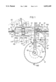
- FIG. 1 is a side view of an exemplary embodiment of a lashing device in accordance with the invention
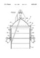
- FIG. 2 is a partial end view of the lashing device in accordance with FIG. 1 as seen in the longitudinal direction of the conductor,
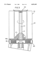
- FIG. 3 is an enlarged view of the mounting of a supply reel on a journal
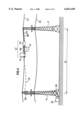
- FIG. 4 is a diagrammatic view of a modification of the lashing method according to the invention.
- FIG. 1 shows a lashing device AV for attaching an optical cable OC to a stranded conductor ES of a high-voltage overhead line.
- the stranded conductor may be an overhead ground cable or a phase cable.
- the optical cable OC is arranged on a supply drum VT, which is mounted for rotation in a U-shaped bracket BG, which has bracket arms BG1 and BG2 (see FIG. 2).
- the supply drum VT is suspended, by means of a rotatable axle DT, in hooks HK1 and HK2, which are arranged at the end of the two bracket arms BG1 and BG2.
- the rotatable axle DT is mounted with respect to the bracket arms BG1 and BG2 by means of ball bearings KL1 and KL2, in order to keep the haul-off forces as low as possible.
- retention eyelets OS1 and OS2 are arranged at each of its outer ends.
- a lock is arranged at each of the openings of the hooks see lock VE1 (FIG. 1) HK1.
- suitable brake devices are to be provided. As can be seen also from FIG. 2, these devices may act on the outside of the supply drum VT (braking elements BT1 and BT2). In addition, or independently of this, it is also possible to provide a further braking device for the optical cable OC itself. This braking device acts directly on the respective cable and prevents an excessively large loop from being formed.
- BC1 and BC2 two of these braking devices which act on the cable are present and are denoted by BC1 and BC2. They are advantageously designed as brush brakes and are arranged offset by 180°.
- a guide device LE (e.g. designed as a guide plate) is provided for guiding and feeding the optical cable to the particular conductor ES, which guide device narrows in the direction of passage, is curved in the direction of passage of the cable OC and forms a trough-like a groove-like depression in which the cable OC is reliably guided.
- This guide device LE has a rim LR1 and LR2 (FIG. 2) which is drawn up laterally, which rim prevents the optical cable OC from springing out of the curved guide path.
- the guide device LE is advantageously held on a pin AE in such a way that it can be swung down, so that it can be swung down into a position LE* (cf. FIG. 1), if, for example, the lashing device is to be moved or guided around a pylon.
- the lashing device AV has a tubular sleeve RH, which has a longitudinal slot RS (only part of which can be seen here), which runs in the direction of the axis of the conductor ES, i.e. running from left to right in the drawing.
- the lashing device AV can be attached to the conductor ES from the side.
- the slot RS lies below the optical cable OC and hence also below the conductor ES, thus forming a protection against these elements springing out.
- the slotted sleeve RH is fixedly connected to the main supporting element HT, serving as a crossarm, which element provides the connection to the holding bracket BG for the cable supply drum VT.
- the lashing device AV comprises, in a fixedly integrated manner, the cable drum VT and the actual lashing part with the tubular sleeve RH, the two parts being fixedly connected to one another via the crossarm HT.
- the lashing device AV is guided on the conductor ES by means of at least two wheels, and one of these wheels, in the present case the front wheel AR, is designed as a driving wheel.
- This wheel AR is used to generate the requisite driving force for applying the lashing elements.
- This wheel AR is therefore in frictional engagement with the surface of the conductor ES, in which case the wheel may expediently be provided with a coating which increases the friction, for example of rubber or the like.
- the further or additional wheel or wheels (in this case only a single exit-side wheel FR is shown) are used to support the lashing device AV on the conductor ES. All the wheels used have on their circumference a groove profile, the size of which is matched to the diameters of the conductor ES.
- a first bevel gear SR1 is connected to the driving wheel AR, which bevel gear transmits the revolving movement of this wheel to a second, smaller bevel gear KR1.
- This bevel gear KR1 is connected, preferably by means of a universal joint, to a shaft WL which runs inside the tubular sleeve RH and is connected at its other end, preferably also by means of a universal joint, to a flange which has a bevel gear SR2 on the outside.
- a supply reel VS1 which is indicated in dashed lines, is provided, which supply reel is arranged in such a manner that it can revolve about its longitudinal axis LA1, as is explained in more detail with reference to FIG. 3. Moreover, it is intended that this supply reel VS1 should rotate about an axis LA3 which lies symmetrically, i.e. approximately in the center, between the conductor ES and the optical cable OC.
- a revolving sleeve DH1 which serves as a support for the supply reel VS1, is mounted for rotation on the slotted tubular sleeve RH.
- the supply reel VS1 can be made to rotate about the axis LA3, because the flange which has the bevel gear SR2 is fixedly connected to the revolving sleeve DH1.
- the force is transmitted via one or more transmission elements which are preferable, bevel gears.
- the outline of the rotational movement of the supply reel VS1 in the event of rotation of the revolving sleeve DH1 is also illustrated in dashed lines.
- the revolving sleeve DH1 has a grip HG1, by means of which it can be attached to the outside of the slotted tubular sleeve RH after the latter has been attached to the conductor ES.
- the revolving sleeve also has a longitudinal slot which is not shown here and which extends in the direction of axis LA3.
- the lashing element AE1 is pulled off the supply reel VS1 and passes outward over corresponding guide devices, e.g. a flyer FL which also rotates with the reel VS1 and, from here, runs at an angle onto the combination of conductor ES and optical cable OC so that the lashing element AE1 is wound continuously onto this combination.
- a flyer FL which also rotates with the reel VS1 and, from here, runs at an angle onto the combination of conductor ES and optical cable OC so that the lashing element AE1 is wound continuously onto this combination.
- a bevel gear SR3 is provided, in which a pair of bevel gears KR2 and KR3, which can revolve only about their longitudinal axis but are otherwise fixed, engages.
- the revolving movement provided by the driving wheel AR is transmitted to the bevel gear SR3, which is flanged onto a revolving sleeve DH2, this revolving sleeve likewise being able to rotate about the slotted tubular sleeve RH.
- a supply reel VS2 which can revolve about its longitudinal axis is provided on the revolving sleeve DH2, sleeve with the supply reel VS2 rotates in the opposite direction of the arrow PF2 to the direction of arrow PF1 for the revolving sleeve DH1 manner to apply a crosslay with the two lashing elements AE1 and AE2.
- the axes of rotation LA1 and LA2 of the supply reels VS1 and VS2 include an acute angle with the longitudinal axis LA3 of the cable-conductor combination, and specifically they are inclined toward the haul-off direction, i.e. to the left in the present example.
- the angular deviation from 90° preferably approximately corresponds to the wrap-around angle of the lashing elements on the conductor ES, i.e. it advantageously lies between approximately 10° and 20°, preferably around 15°.
- FIG. 3 shows part of the annular outer delimitation of the revolving sleeve DH1, in section.
- a journal or shaft ZA1 is fixedly attached to said sleeve, to which journal, in turn, the supply reel VS1 with the lashing element AE1 (which in this figure is shown only in the form of a block) is attached by means of a quick-acting closure element SVE, thus forming a center sleeve.
- the quick-acting closure SVE is selected in such a way that the supply reel can rotate with respect to the fixed journal ZA1, i.e. it expediently contains a ball bearing or roller bearing.
- the supply reel VS1 is placed on a bottom part UT1 and held fixedly thereon, which bottom part is mounted, by means of ball bearings or the like (not shown in more detail here), in such a manner that it can revolve with respect to the journal ZA1.
- a hysteresis disk or magnetic disk MB2 is attached to the bottom part UT1, which disk rotates, together with the supply reel VS1, about the axis LA1.
- a permanent magnet MB1 preferably a ring magnet, is arranged in the region of the revolving sleeve DH1, separated from the disk MB2 by a gap, the rotating movement of the supply reel or the magnetic disk MB2 with respect to the magnet MB1 generating a braking force which prevents the lashing element AE1 from running off too quickly and hence forming undesirable loops.
- the magnetic brakes it is also possible to use all other known braking devices, such as for example brush brakes, drum brakes or the like, in order to haul the lashing element AE1 off the supply reel VS1 under tensile stress and thus to exert a corresponding tensile stress on the conductor-cable combination ES/OC.
- tape-like structures are used as the lashing elements, e.g. AE1, with the result that the thickness and pressure can be kept relatively low even under high and fixed tensile stresses on the lashing element at the optical cable OC.
- self-adhesive lashing elements are used, because these hold the conductor-cable combination ES/OC particularly successfully and securely.
- These lashing elements may also, in addition, be provided with a reinforcement fabric or an additional reinforcement layer in the form of filaments or rovings and the like, which correspondingly increases their tensile force and their robustness.
- the longitudinal movement of the lashing device AV can be ensured by means of a drive unit AM which is structurally connected thereto and contains, for example, an internal combustion engine or a motor which is powered electrically via suitable power supply lines.
- This drive unit AM runs along the conductor ES by means of running wheels RM1 and RM2 and a corresponding counterpressure wheel RM3 and is connected in an articulated manner to the actual lashing device AV by way of a coupling KP.
- a coupling KP it is also possible to use a rope or rod or the like.
- the fiber-optic cable which is to be installed is continuously attached along a conductor of the high-voltage overhead line in an arrangement which is combined to form a cable train, using a continuous attachment means in the form of a wound strip.
- the cable train comprises a traveling trolley, a cable trailer and a lashing machine, which are fixedly coupled to one another and form a single unit.
- the cable train as a whole is pulled along a suspension span by the traveling trolley, the fiber-optic cable which is situated in a cable drum in the cable trailer being unwound and, with the aid of the lashing machine of the cable train, being attached preferably to the overhead ground cable of the high-voltage overhead line.
- attachment takes place using a continuous wound tape which is wound around the conductor and the fiber-optic cable in the form of a spiral.
- This wound tape comprises, by way of example, a glass or plastic tape which is wound in a simple, continuous manner.
- the fiber-optic cable which is to be installed can be lashed either to the overhead ground cable or to a phase cable of the high-voltage overhead line.
- the cable train can be moved along within a suspension span using a drive unit in the traveling trolley, in which case a remote control is advantageously used for this purpose.
- the cable train can also be moved along with the aid of a dielectric drawing-in wire which is attached to the traveling trolley and at the end of the suspension span is guided over diverting rollers to a wire winch.
- the fiber-optic cable which is to be installed and is wound on the cable drum of the cable trailer is generally very lightweight (approx. 20 g/m) and runs off the cable drum under slight braking, which drum is installed in a frame provided with running rollers, in the form of the cable trailer.
- the three functional components of the traveling trolley, cable trailer and lashing machine are coupled to one another and are thus guided jointly along a suspension span.
- the cable train In the event of faults occurring, such as for example in the event of failure of the remote control, it is provided, in the event of such a fault, for the cable train to be coupled to an additional traveling trolley from the end of the suspension span and to be pulled to the end of the suspension span. This ensures that faults in the drive system of the cable train can be overcome in a relatively simple manner.
- FIG. 4 shows a suspension span SF between two pylons M of a high-voltage overhead line, with the phase cables or voltage cables SS and an overhead ground cable ES.
- a fiber-optic cable is being installed on the overhead ground cable ES of the high-voltage overhead line, using a cable train KZ.
- This cable train KZ comprises individual functional components which are fixedly coupled to one another, namely a traveling trolley LK, a cable trailer KW with a cable drum KT, and a lashing machine LM.
- a wound tape (lashing tape) WB is wound around the fiber-optic cable OC4, which is being installed on the conductor ES and the overhead ground conductor ES in the form of a spiral, this figure, by way of example, showing the winding in a crosslay with two wound tapes. In more simple cases, winding can also take place with only one wound tape.
- the cable trailer KW comprises a cable drum KT, on which the fiber-optic cable OC4 to be installed is wound.
- the traveling trolley LK At the head of the cable train KZ there is situated the traveling trolley LK, which is pulled along the suspension span SF either with the aid of a dielectric drawing-in wire ZS or by means of its own drive unit.
- a drawing-in wire ZS is used, the latter is coupled to the traveling trolley from the end of the suspension span and is guided downward to an additional wire winch ZW via diverting rollers UR on the pylon M.
- a dedicated drive unit it is expedient for it to be controlled with the aid of a remote control device, so that there is no need to install additional lines or cables.
Landscapes
- Physics & Mathematics (AREA)
- General Physics & Mathematics (AREA)
- Optics & Photonics (AREA)
- Electric Cable Installation (AREA)
- Light Guides In General And Applications Therefor (AREA)
- Electric Cable Arrangement Between Relatively Moving Parts (AREA)
Applications Claiming Priority (5)
| Application Number | Priority Date | Filing Date | Title |
|---|---|---|---|
| DE1996114839 DE19614839A1 (de) | 1996-04-15 | 1996-04-15 | Vorrichtung und Verfahren zum Anlaschen eines optischen Kabels an ein Leitungsseil einer Freileitung |
| DE19614839 | 1996-04-15 | ||
| DE19616853 | 1996-04-26 | ||
| DE1996116853 DE19616853C1 (de) | 1996-04-26 | 1996-04-26 | Verfahren zur Installation eines Lichtwellenleiterkabels an einem Seil einer Hochspannungsfreileitung |
| PCT/DE1997/000741 WO1997039372A1 (de) | 1996-04-15 | 1997-04-11 | Vorrichtung und verfahren zum anlaschen eines optischen kabels an ein leitungsseil einer freileitung |
Publications (1)
| Publication Number | Publication Date |
|---|---|
| US6032449A true US6032449A (en) | 2000-03-07 |
Family
ID=26024758
Family Applications (1)
| Application Number | Title | Priority Date | Filing Date |
|---|---|---|---|
| US09/171,088 Expired - Lifetime US6032449A (en) | 1996-04-15 | 1997-04-11 | Process and device for splicing an optical cable to the conductor strand of an aerial line |
Country Status (7)
| Country | Link |
|---|---|
| US (1) | US6032449A (de) |
| CN (1) | CN1115575C (de) |
| AR (1) | AR006602A1 (de) |
| AT (1) | AT410046B8 (de) |
| BR (1) | BR9708668A (de) |
| RU (1) | RU2171486C2 (de) |
| WO (1) | WO1997039372A1 (de) |
Cited By (14)
| Publication number | Priority date | Publication date | Assignee | Title |
|---|---|---|---|---|
| EP1172675A3 (de) * | 2000-07-11 | 2004-08-25 | Reinhard Schuster | Kabelverlegungsmaschine und Verfahren zum Verlegen von Kabeln |
| WO2004099840A1 (en) * | 2003-05-06 | 2004-11-18 | Pirelli Telecom Cables Y Sistemas España, S.L. | Optical aerial line and method of installation thereof |
| US20050247136A1 (en) * | 2004-05-07 | 2005-11-10 | Cross Joseph A | Wireline extensometer |
| RU2372633C2 (ru) * | 2007-11-12 | 2009-11-10 | Шишлов Юрий Николаевич | Навивочная машина волоконно-оптического кабеля |
| WO2015114336A3 (en) * | 2014-01-31 | 2015-12-10 | Afl Global | Jumper insulator |
| RU2606242C2 (ru) * | 2015-06-02 | 2017-01-10 | Юрий Николаевич Федоров | Навивочная машина волоконно-оптического кабеля |
| CN111217196A (zh) * | 2019-12-26 | 2020-06-02 | 安徽微威胶件集团有限公司 | 一种橡胶管专用悬挂支架 |
| CN112234499A (zh) * | 2020-09-21 | 2021-01-15 | 石河子大学 | 一种架空线路飞走蛇形巡检机器人的巡检方法 |
| CN113098599A (zh) * | 2021-04-25 | 2021-07-09 | 国网山西省电力公司信息通信分公司 | 一种配网通信光缆故障定位装置 |
| US11169351B2 (en) * | 2019-01-17 | 2021-11-09 | Facebook, Inc. | Systems and methods for installing fiber optic cable about a powerline conductor |
| CN114421361A (zh) * | 2021-12-27 | 2022-04-29 | 福建省送变电工程有限公司 | 一种输电线路架空输电线路工程架线施工滑车 |
| US12081009B2 (en) | 2021-03-09 | 2024-09-03 | ELECTRO SAGUENAY LTéE | Autonomous cable lasher comprising an onboard torque compensation mechanism |
| US12088079B2 (en) | 2021-03-09 | 2024-09-10 | ELECTRO SAGUENAY LTéE | Autonomous cable lasher comprising lashing wire dispensers that apply opposed radial force components |
| US12228783B1 (en) * | 2020-07-07 | 2025-02-18 | Meta Platforms, Inc. | Robotic system obstacle recognition |
Families Citing this family (12)
| Publication number | Priority date | Publication date | Assignee | Title |
|---|---|---|---|---|
| DE19857131A1 (de) * | 1998-12-11 | 2000-06-15 | Alcatel Sa | Verfahren zur Installation eines Kabels an einem Seil einer Hochspannungsfreileitung |
| GB2378212A (en) * | 2001-08-02 | 2003-02-05 | Ibm | Preventing cable damage during installation |
| RU2205486C1 (ru) * | 2001-09-17 | 2003-05-27 | Закрытое акционерное общество "Телеком Транспорт АДС" | Способ воздушной прокладки волоконно-оптического кабеля по проводу воздушной линии электропередач |
| US7086539B2 (en) * | 2002-10-21 | 2006-08-08 | Adc Telecommunications, Inc. | High density panel with rotating tray |
| CN100363771C (zh) * | 2005-08-19 | 2008-01-23 | 桂林师慧信息产业有限公司 | 光缆施工缠绕机 |
| RU2360345C1 (ru) * | 2008-02-07 | 2009-06-27 | ООО "Оптиктелеком Строй" | Способ прокладки самонесущего оптического кабеля по опорам высоковольтных линий электропередачи на переходах через препятствия |
| CN101630049B (zh) * | 2009-08-19 | 2014-12-17 | 王甘雨 | 一种架空光缆线路施工机具 |
| CN101644802B (zh) * | 2009-09-04 | 2011-03-23 | 雷步忠 | 储缆式旋转光缆信号传输装置 |
| CN102262274B (zh) * | 2010-10-11 | 2012-11-28 | 梁红 | 光缆架空敷设车 |
| JP2015515250A (ja) * | 2012-03-30 | 2015-05-21 | エルファー エルエルシー | 伝送ライン上を移動し、支援するよう構成されたモバイルデバイス |
| US10613289B2 (en) * | 2018-02-09 | 2020-04-07 | Facebook, Inc. | Apparatuses, systems, and methods for installing fiber optic cable using preexisting electrical power infrastructure |
| CN111708139B (zh) * | 2020-06-19 | 2022-04-19 | 网建通信建设有限公司 | 一种光缆架设装置以及其架设方法 |
Citations (13)
| Publication number | Priority date | Publication date | Assignee | Title |
|---|---|---|---|---|
| US2402172A (en) * | 1943-10-29 | 1946-06-18 | Victor M Macy | Cable lasher |
| US2592943A (en) * | 1949-02-07 | 1952-04-15 | Dory J Neale | Lashing machine for aerial cables |
| US2663544A (en) * | 1953-12-22 | Cable lashing machine | ||
| US3162992A (en) * | 1962-12-20 | 1964-12-29 | Amp Inc | Cable installing and wrapping apparatus |
| US4274574A (en) * | 1980-01-16 | 1981-06-23 | Illinois Tool Works Inc. | Linear motion cable drive |
| US4311299A (en) * | 1981-02-02 | 1982-01-19 | Elliott Jr Alton D | Cable lasher |
| US4424954A (en) * | 1982-03-18 | 1984-01-10 | Communications Systems, Inc. | Fiber optic cable tension loader |
| DE3228239A1 (de) * | 1982-07-28 | 1984-02-02 | Siemens AG, 1000 Berlin und 8000 München | Verfahren zum anlaschen von lichtwellenleiter-kabeln an hochspannungsseilen |
| DE3228227A1 (de) * | 1982-07-28 | 1984-02-02 | Siemens AG, 1000 Berlin und 8000 München | Vorrichtung zum anbringen von kabeln an tragseilen oder aehnlichem |
| GB2173471A (en) * | 1985-04-03 | 1986-10-15 | Furukawa Electric Co Ltd | Method of winding optical cable to aerial wire |
| DE3702781A1 (de) * | 1987-01-30 | 1988-08-11 | Siemens Ag | Optisches luftkabel und einrichtung zur aufseilung desselben |
| WO1996032661A1 (en) * | 1995-04-11 | 1996-10-17 | Focas Limited | An apparatus for wrapping fibre optic cable around and overhead line |
| WO1996038892A1 (de) * | 1995-06-02 | 1996-12-05 | Siemens Aktiengesellschaft | Verfahren zur installation eines lichtwellenleiter-kabels an einem seil einer hochspannungsfreileitung |
Family Cites Families (2)
| Publication number | Priority date | Publication date | Assignee | Title |
|---|---|---|---|---|
| CH549298A (it) * | 1971-06-21 | 1974-05-15 | Crippa Carla | Macchina per fissare un fascio di cavi ad un cavo portante aereo. |
| EP0191295A3 (de) * | 1985-02-13 | 1988-11-09 | Siemens Aktiengesellschaft | Vorrichtung zum Anbringen von Kabeln an Tragseilen |
-
1997
- 1997-02-11 AT AT0904097A patent/AT410046B8/de not_active IP Right Cessation
- 1997-04-11 RU RU98120449/28A patent/RU2171486C2/ru not_active IP Right Cessation
- 1997-04-11 WO PCT/DE1997/000741 patent/WO1997039372A1/de not_active Ceased
- 1997-04-11 BR BR9708668A patent/BR9708668A/pt active Search and Examination
- 1997-04-11 US US09/171,088 patent/US6032449A/en not_active Expired - Lifetime
- 1997-04-11 AR ARP970101442A patent/AR006602A1/es active IP Right Grant
- 1997-04-11 CN CN97195419A patent/CN1115575C/zh not_active Expired - Fee Related
Patent Citations (13)
| Publication number | Priority date | Publication date | Assignee | Title |
|---|---|---|---|---|
| US2663544A (en) * | 1953-12-22 | Cable lashing machine | ||
| US2402172A (en) * | 1943-10-29 | 1946-06-18 | Victor M Macy | Cable lasher |
| US2592943A (en) * | 1949-02-07 | 1952-04-15 | Dory J Neale | Lashing machine for aerial cables |
| US3162992A (en) * | 1962-12-20 | 1964-12-29 | Amp Inc | Cable installing and wrapping apparatus |
| US4274574A (en) * | 1980-01-16 | 1981-06-23 | Illinois Tool Works Inc. | Linear motion cable drive |
| US4311299A (en) * | 1981-02-02 | 1982-01-19 | Elliott Jr Alton D | Cable lasher |
| US4424954A (en) * | 1982-03-18 | 1984-01-10 | Communications Systems, Inc. | Fiber optic cable tension loader |
| DE3228239A1 (de) * | 1982-07-28 | 1984-02-02 | Siemens AG, 1000 Berlin und 8000 München | Verfahren zum anlaschen von lichtwellenleiter-kabeln an hochspannungsseilen |
| DE3228227A1 (de) * | 1982-07-28 | 1984-02-02 | Siemens AG, 1000 Berlin und 8000 München | Vorrichtung zum anbringen von kabeln an tragseilen oder aehnlichem |
| GB2173471A (en) * | 1985-04-03 | 1986-10-15 | Furukawa Electric Co Ltd | Method of winding optical cable to aerial wire |
| DE3702781A1 (de) * | 1987-01-30 | 1988-08-11 | Siemens Ag | Optisches luftkabel und einrichtung zur aufseilung desselben |
| WO1996032661A1 (en) * | 1995-04-11 | 1996-10-17 | Focas Limited | An apparatus for wrapping fibre optic cable around and overhead line |
| WO1996038892A1 (de) * | 1995-06-02 | 1996-12-05 | Siemens Aktiengesellschaft | Verfahren zur installation eines lichtwellenleiter-kabels an einem seil einer hochspannungsfreileitung |
Cited By (23)
| Publication number | Priority date | Publication date | Assignee | Title |
|---|---|---|---|---|
| EP1172675A3 (de) * | 2000-07-11 | 2004-08-25 | Reinhard Schuster | Kabelverlegungsmaschine und Verfahren zum Verlegen von Kabeln |
| WO2004099840A1 (en) * | 2003-05-06 | 2004-11-18 | Pirelli Telecom Cables Y Sistemas España, S.L. | Optical aerial line and method of installation thereof |
| US20070009215A1 (en) * | 2003-05-06 | 2007-01-11 | Sales Casals Lluis R | Optical aerial line and method of installation thereof |
| US7352936B2 (en) | 2003-05-06 | 2008-04-01 | Prysmian Cables Y Sistemas, S.L. | Optical aerial line and method of installation thereof |
| US20050247136A1 (en) * | 2004-05-07 | 2005-11-10 | Cross Joseph A | Wireline extensometer |
| US7222540B2 (en) | 2004-05-07 | 2007-05-29 | Call & Nicholas Instruments, Inc. | Wireline extensometer |
| RU2372633C2 (ru) * | 2007-11-12 | 2009-11-10 | Шишлов Юрий Николаевич | Навивочная машина волоконно-оптического кабеля |
| WO2015114336A3 (en) * | 2014-01-31 | 2015-12-10 | Afl Global | Jumper insulator |
| US10254501B2 (en) | 2014-01-31 | 2019-04-09 | Afl Global | Jumper insulator for optical cables used with high voltage cables |
| RU2606242C2 (ru) * | 2015-06-02 | 2017-01-10 | Юрий Николаевич Федоров | Навивочная машина волоконно-оптического кабеля |
| CN113748367A (zh) * | 2019-01-17 | 2021-12-03 | 脸谱公司 | 围绕电力线路导体安装光纤电缆的系统和方法 |
| US12092889B1 (en) | 2019-01-17 | 2024-09-17 | Meta Platforms, Inc. | Systems and methods for installing fiber optic cable onto a powerline conductor |
| US11668891B1 (en) | 2019-01-17 | 2023-06-06 | Meta Platforms, Inc. | Systems and methods for installing fiber optic cable onto a powerline conductor |
| US11169351B2 (en) * | 2019-01-17 | 2021-11-09 | Facebook, Inc. | Systems and methods for installing fiber optic cable about a powerline conductor |
| CN111217196A (zh) * | 2019-12-26 | 2020-06-02 | 安徽微威胶件集团有限公司 | 一种橡胶管专用悬挂支架 |
| US12228783B1 (en) * | 2020-07-07 | 2025-02-18 | Meta Platforms, Inc. | Robotic system obstacle recognition |
| CN112234499B (zh) * | 2020-09-21 | 2022-02-08 | 石河子大学 | 一种架空线路飞走蛇形巡检机器人的巡检方法 |
| CN112234499A (zh) * | 2020-09-21 | 2021-01-15 | 石河子大学 | 一种架空线路飞走蛇形巡检机器人的巡检方法 |
| US12081009B2 (en) | 2021-03-09 | 2024-09-03 | ELECTRO SAGUENAY LTéE | Autonomous cable lasher comprising an onboard torque compensation mechanism |
| US12088079B2 (en) | 2021-03-09 | 2024-09-10 | ELECTRO SAGUENAY LTéE | Autonomous cable lasher comprising lashing wire dispensers that apply opposed radial force components |
| CN113098599B (zh) * | 2021-04-25 | 2022-03-15 | 国网山西省电力公司信息通信分公司 | 一种配网通信光缆故障定位装置 |
| CN113098599A (zh) * | 2021-04-25 | 2021-07-09 | 国网山西省电力公司信息通信分公司 | 一种配网通信光缆故障定位装置 |
| CN114421361A (zh) * | 2021-12-27 | 2022-04-29 | 福建省送变电工程有限公司 | 一种输电线路架空输电线路工程架线施工滑车 |
Also Published As
| Publication number | Publication date |
|---|---|
| ATA904097A (de) | 2002-05-15 |
| BR9708668A (pt) | 1999-08-03 |
| AT410046B8 (de) | 2003-06-25 |
| AT410046B (de) | 2003-01-27 |
| RU2171486C2 (ru) | 2001-07-27 |
| CN1221495A (zh) | 1999-06-30 |
| WO1997039372A1 (de) | 1997-10-23 |
| AR006602A1 (es) | 1999-09-08 |
| CN1115575C (zh) | 2003-07-23 |
Similar Documents
| Publication | Publication Date | Title |
|---|---|---|
| US6032449A (en) | Process and device for splicing an optical cable to the conductor strand of an aerial line | |
| RU98120449A (ru) | Устройство и способ для крепления оптического кабеля на тросе электрической воздушной линии | |
| JPS61230103A (ja) | 架空線への光ケ−ブルの巻付方法 | |
| CN209291705U (zh) | 一种铠装缠绕机 | |
| CN110844712B (zh) | 一种岸电线缆管理装置 | |
| WO1996032661A1 (en) | An apparatus for wrapping fibre optic cable around and overhead line | |
| EA032366B1 (ru) | Навивочная машина для навивки волоконно-оптического кабеля | |
| JPH03120176A (ja) | ケーブルまたは類似物をリールの外側表面に複式に巻き付ける方法及び該方法実施のための装置 | |
| US4978086A (en) | Deployment of towed aircraft decoys | |
| RU161996U1 (ru) | Механизм навивки для устройства для навивки волоконно-оптического кабеля на носитель | |
| CN100353628C (zh) | 引导电缆进出电缆框的装置 | |
| RU2309109C1 (ru) | Устройство для навивки волоконно-оптического кабеля на несущий провод | |
| EP4071101B1 (de) | Seilspannvorrichtung mit unabhängig drehbarem flansch | |
| JP2851090B2 (ja) | 架空線への光ケーブル巻付け布設方法 | |
| RU2073290C1 (ru) | Способ навива кабеля на провода и устройство для его осуществления | |
| JP2003511321A (ja) | 荷を取り扱うことに使用するための方法及び装置 | |
| JP2002017011A (ja) | 架線敷設工法 | |
| KR101829821B1 (ko) | 전선연합시스템 | |
| US5644905A (en) | Stranding device with an exchangeable supply member and an associated method | |
| CN112290457A (zh) | 一种碳纤维复合芯导线的施工方法 | |
| CA1232590A (en) | Cable winder assembly | |
| CN218371002U (zh) | 绞臂用的张力控制装置 | |
| US20100329791A1 (en) | System for deployment of a seabed cable distribution network | |
| CN116553307B (zh) | 一种放线机构及包括该放线机构的放线车 | |
| JPH0355585Y2 (de) |
Legal Events
| Date | Code | Title | Description |
|---|---|---|---|
| AS | Assignment |
Owner name: SIEMENS AKTIENGESELLSCHAFT, GERMANY Free format text: ASSIGNMENT OF ASSIGNORS INTEREST;ASSIGNORS:EINSLE, GUNTER;KREUTZ, DIETER;MAYER, ERNST;REEL/FRAME:009630/0874 Effective date: 19970327 |
|
| STCF | Information on status: patent grant |
Free format text: PATENTED CASE |
|
| AS | Assignment |
Owner name: CCS TECHNOLOGY, INC., DELAWARE Free format text: ASSIGNMENT OF ASSIGNORS INTEREST;ASSIGNOR:SIEMENS AKTIENGESELLSCHAFT;REEL/FRAME:013362/0204 Effective date: 20000131 |
|
| FPAY | Fee payment |
Year of fee payment: 4 |
|
| FPAY | Fee payment |
Year of fee payment: 8 |
|
| FPAY | Fee payment |
Year of fee payment: 12 |