US5949500A - Degaussing coil fixing technique - Google Patents
Degaussing coil fixing technique Download PDFInfo
- Publication number
- US5949500A US5949500A US08/805,335 US80533597A US5949500A US 5949500 A US5949500 A US 5949500A US 80533597 A US80533597 A US 80533597A US 5949500 A US5949500 A US 5949500A
- Authority
- US
- United States
- Prior art keywords
- frame
- degaussing coil
- holder
- fixing
- assembling
- Prior art date
- Legal status (The legal status is an assumption and is not a legal conclusion. Google has not performed a legal analysis and makes no representation as to the accuracy of the status listed.)
- Expired - Fee Related
Links
Images


Classifications
-
- H—ELECTRICITY
- H04—ELECTRIC COMMUNICATION TECHNIQUE
- H04N—PICTORIAL COMMUNICATION, e.g. TELEVISION
- H04N9/00—Details of colour television systems
- H04N9/12—Picture reproducers
- H04N9/16—Picture reproducers using cathode ray tubes
- H04N9/29—Picture reproducers using cathode ray tubes using demagnetisation or compensation of external magnetic fields
-
- H—ELECTRICITY
- H04—ELECTRIC COMMUNICATION TECHNIQUE
- H04N—PICTORIAL COMMUNICATION, e.g. TELEVISION
- H04N5/00—Details of television systems
- H04N5/64—Constructional details of receivers, e.g. cabinets or dust covers
- H04N5/645—Mounting of picture tube on chassis or in housing
Definitions
- the present invention relates to a degaussing coil of a monitor, and more particularly to a degaussing coil fixing technique, wherein, after performing a primary preparatory operation of just inserting four shaping holders into a frame of the monitor, the operations of shaping a degaussing coil by means of the degaussing holders and of fixing the frame are simultaneously carried out while the frame is fixed onto a front cover by putting the degaussing coil on an electron tube, thereby improving workability and reducing the number of workers needed for assembly of the monitor.
- holders are provided for fixing a degaussing coil to a frame of the monitor in advance and the degaussing coil is inserted so as to be seated in the holders and the frame is affixed to a front cover.
- the holders are fitted into the frame of the monitor and the degaussing coil is inserted into the holders which are affixed to the frame and the frame fitted with the degaussing coil is then fixed to the front cover which is mounted to an electron tube.
- the present invention is devised to solve the foregoing problems. Therefore, it is an object of the present invention to provide a degaussing coil fixing apparatus of a monitor and method therefor, wherein, after performing a primary preparing operation of just inserting four shaping holders into a frame of the monitor, the operations of shaping a degaussing coil by means of the degaussing holders and of fixing the frame are simultaneously carried out while the frame is fixed onto a front cover by putting the degaussing coil on an electron tube, thereby improving workability and reducing the number of workers needed to assemble the monitor.
- a degaussing coil fixing apparatus of a monitor basically includes a seating part with an elastic force for fixing a degaussing coil by being bent to have a radius which is set to be integrally formed with a holder body of a shaping holder assembled to a frame in a body, and a hooking plate extending from a free end of the seating part for smoothly catching the degaussing coil to guide it to the seating part when assembling the frame to a front cover.
- an assembling fixing unit of the frame and the shaping holder is provided such that the frame includes a holder seating groove disposed at a set place of the frame, and a holder assembling hole formed into the holder seating groove. Also, the holder includes the holder body seated onto the holder seating groove for setting the assembling position of the holder, and a holder fixing snap integrally formed to project from the holder body for being inserted into the holder assembling hole to be assembled in a body.
- a hooking plate of the shaping holder is inwardly bent for smoothly catching the degaussing coil.
- a degaussing coil fixing method of a monitor which is performed by assembling shaping holders to inner sides of a frame, and coupling the frame to a front cover coupled to an electron tube to which a degaussing coil is arranged. The fixing of the frame and degaussing coil are simultaneously carried out.
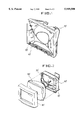
- FIG. 1 is a perspective view of a frame showing the fixing of an earlier degaussing coil
- FIG. 2 is an exploded perspective view showing an assembling process of an earlier monitor
- FIG. 3 is an exploded perspective view showing an assembling process of a monitor according to the present invention.
- FIG. 4 is an enlarged view, with portions broken away of an assembling part of the shaping holder according to the present invention
- FIG. 5 is an enlarged view, with portions broken away showing the fixing of the degaussing coil according to the present invention.
- FIGS. 6A and 6B are a side view and a bottom end view, respectively, with portions broken away of the shaping holder according to the present invention.
- An assembling unit of an earlier monitor is provided such that holders 20' for fixing a degaussing coil 40' are fitted to be fixed to a frame 10' of the monitor in advance, and degaussing coil 40' is inserted so as to be seated in holders 20', thereby assembling frame 10' to a front cover 30'.
- a degaussing coil fixing apparatus of a monitor and method therefor according to the present invention will be described in detail with reference to the preferred embodiment shown in FIGS. 3 to 6B.
- the degaussing coil fixing apparatus of the monitor is constructed in such a manner that a seating part 22 with an elastic force is bent for fixing the degaussing coil by having a radius set to be integrally formed with a holder body 21 of a shaping holder 20 which is integrally assembled to a frame 10. Also, a hooking plate 23 extending from the free end of seating part 22 upwardly catches a degaussing coil 40 to guide it to the seating part 22 when assembling the frame 10 and a front cover 30.
- the frame 10 includes a holder seating groove 11 disposed at a preset place thereof and a holder assembling hole 12 formed into holder seating groove 11.
- the holder 20 includes a holder body 21 seated onto holder seating groove 11 for setting the assembling position, and a holder fixing snap 24, integrally formed to protrude from the holder body 21, is inserted into holder assembling hole 12 to be integrally assembled therewith.
- two holder fixing snaps 24 project at two places to inhibit the movement of the holder 20.
- the hooking plate 23 of the holder 20 is inwardly bent to slant to smoothly catch the degaussing coil 40.
- the front cover 30 is assembled with the electron tube 50 in such a manner that fixing plates 51 integrally formed at respective corners of the electron tube 50 are correspondent to front tube fixing bosses 31 which protrude from the inner side of respective corners of the front cover 30, and separate assembling screws 60 are employed to assemble the front cover 30 and electron tube 50 in a body.
- An assembling unit of frame 10 and front cover 30 forces respective assembling holes 13 formed along the outer flange of frame 10 to correspond to respective frame fixing bosses 32 projecting from respective inner sides of front cover 30, and separate assembling screws (not shown) are employed to execute the assembling.
- the primary assembling is performed under the state that the frame 10 of the monitor is prepared. That is, once the holder fixing snaps 24 of shaping holder 20 are inserted into the holder assembling holes 12 of the frame 10, the holder body 21 is seated onto the holder seating groove 11 of frame 10 to set the assembling position and, at the same time, corresponds to the plane of the frame 10 so as not to obstruct the guiding insertion of the degaussing coil 40.
- the holder fixing snaps 24 of the shaping holder 20 are constricted in the typical way when frame 10 is fitted through the holder assembling holes 12. Then, upon passing the holder assembling holes 12, the holder fixing snaps 24 catch the plane of the frame 10 to block the separation of frame 10 unless an external force is applied thereon while the hooking jaw is elastically widened in the radial direction. Therefore, the primary assembling work of assembling shaping holder 20 to frame 10 is completed.
- FIG. 3 shows a secondary assembling process according to the present invention, in which degaussing coil 40 is arranged to the fixing position at the upper portion of electron tube 50 integrally assembled to front cover 30, and frame 10 are put on front cover 30. Then, respective shaping holders 20 assembled to frame 10 is placed to the straight upper portion of degaussing coil 40.
- assembling holes 13 of frame 10 are fitted to be coupled with the frame fixing bosses 32 of the front cover 30 by means of the assembling screws, so that hooking plates 23 smoothly catch the degaussing coil 40.
- the guiding of degaussing coil 40 to the seating part 22 means that the seating part 22 is guided toward degaussing coil 40, and the fixing is smoothly carried out the moment degaussing coil 40 is guided to the seating part 22.
- the holder body 21 which is embedded into the holder seating groove 11 of the frame 10 to correspond to the plane of the frame 10 does not impede the guiding of the degaussing coil 40.
- the degaussing coil 40 is smoothly fixed to shaping holders 20 to be able to shorten the assembling operation.
- the primary assembling operation of inserting the shaping holders into the four inner sides of the frame of the monitor is performed in advance, and the secondary assembling operation of fixing the frame into the front cover is performed while the degaussing coil is just put on the electron tube. Then, the operations of shaping the degaussing coil by the degaussing coil holders and fixing the frame can be simultaneously carried out to enhance both operation efficiency and productivity efficiency. Furthermore, the number of workers is reduced to be effective in reducing labor cost.
Landscapes
- Engineering & Computer Science (AREA)
- Multimedia (AREA)
- Signal Processing (AREA)
- Video Image Reproduction Devices For Color Tv Systems (AREA)
- Materials For Medical Uses (AREA)
Applications Claiming Priority (2)
| Application Number | Priority Date | Filing Date | Title |
|---|---|---|---|
| KR96-4536 | 1996-02-24 | ||
| KR1019960004536A KR100265172B1 (ko) | 1996-02-24 | 1996-02-24 | 모니터의 디가우징 코일 고정장치 |
Publications (1)
| Publication Number | Publication Date |
|---|---|
| US5949500A true US5949500A (en) | 1999-09-07 |
Family
ID=19451740
Family Applications (1)
| Application Number | Title | Priority Date | Filing Date |
|---|---|---|---|
| US08/805,335 Expired - Fee Related US5949500A (en) | 1996-02-24 | 1997-02-24 | Degaussing coil fixing technique |
Country Status (2)
| Country | Link |
|---|---|
| US (1) | US5949500A (ko) |
| KR (1) | KR100265172B1 (ko) |
Cited By (1)
| Publication number | Priority date | Publication date | Assignee | Title |
|---|---|---|---|---|
| EP1168837A1 (en) * | 2000-01-31 | 2002-01-02 | Matsushita Electric Industrial Co., Ltd. | Video apparatus, holding device, and method for producing holding device |
Citations (12)
| Publication number | Priority date | Publication date | Assignee | Title |
|---|---|---|---|---|
| US3322998A (en) * | 1964-08-31 | 1967-05-30 | Rca Corp | Color purity correcting apparatus for colored television picture tubes |
| US3872347A (en) * | 1972-04-14 | 1975-03-18 | Tokyo Shibaura Electric Co | Degaussing device for colour cathode ray tubes |
| US3965386A (en) * | 1973-09-13 | 1976-06-22 | U.S. Philips Corporation | Degaussing device for a color television display tube |
| US4643493A (en) * | 1985-07-19 | 1987-02-17 | Rca Corporation | Television chassis |
| US4700260A (en) * | 1986-05-30 | 1987-10-13 | Rca Corporation | Degaussing coil and ground strap mounting arrangement |
| US4812946A (en) * | 1986-10-10 | 1989-03-14 | U.S. Philips Corporation | Demagnetization and earthing device for a picture tube and machine for manufacturing same |
| US5038078A (en) * | 1989-06-05 | 1991-08-06 | Rca Licensing Corporation | Degaussing coil attachment arrangement |
| US5036577A (en) * | 1989-11-30 | 1991-08-06 | Thomson Consumer Electronics, Inc. | Method of forming a shrink fit implosion protection band |
| US5040752A (en) * | 1986-10-01 | 1991-08-20 | Knoll International | Wire management clip |
| US5230257A (en) * | 1991-11-07 | 1993-07-27 | Teleflex Incorporated | Remote control assembly with snap-in terminal |
| US5379117A (en) * | 1990-12-12 | 1995-01-03 | Samsung Electron Devices Co., Ltd. | Supporting member for a VLMF coil |
| US5416595A (en) * | 1993-04-29 | 1995-05-16 | Sony Electronics Inc. | Methods and apparatus for securing a degaussing coil |
-
1996
- 1996-02-24 KR KR1019960004536A patent/KR100265172B1/ko not_active IP Right Cessation
-
1997
- 1997-02-24 US US08/805,335 patent/US5949500A/en not_active Expired - Fee Related
Patent Citations (12)
| Publication number | Priority date | Publication date | Assignee | Title |
|---|---|---|---|---|
| US3322998A (en) * | 1964-08-31 | 1967-05-30 | Rca Corp | Color purity correcting apparatus for colored television picture tubes |
| US3872347A (en) * | 1972-04-14 | 1975-03-18 | Tokyo Shibaura Electric Co | Degaussing device for colour cathode ray tubes |
| US3965386A (en) * | 1973-09-13 | 1976-06-22 | U.S. Philips Corporation | Degaussing device for a color television display tube |
| US4643493A (en) * | 1985-07-19 | 1987-02-17 | Rca Corporation | Television chassis |
| US4700260A (en) * | 1986-05-30 | 1987-10-13 | Rca Corporation | Degaussing coil and ground strap mounting arrangement |
| US5040752A (en) * | 1986-10-01 | 1991-08-20 | Knoll International | Wire management clip |
| US4812946A (en) * | 1986-10-10 | 1989-03-14 | U.S. Philips Corporation | Demagnetization and earthing device for a picture tube and machine for manufacturing same |
| US5038078A (en) * | 1989-06-05 | 1991-08-06 | Rca Licensing Corporation | Degaussing coil attachment arrangement |
| US5036577A (en) * | 1989-11-30 | 1991-08-06 | Thomson Consumer Electronics, Inc. | Method of forming a shrink fit implosion protection band |
| US5379117A (en) * | 1990-12-12 | 1995-01-03 | Samsung Electron Devices Co., Ltd. | Supporting member for a VLMF coil |
| US5230257A (en) * | 1991-11-07 | 1993-07-27 | Teleflex Incorporated | Remote control assembly with snap-in terminal |
| US5416595A (en) * | 1993-04-29 | 1995-05-16 | Sony Electronics Inc. | Methods and apparatus for securing a degaussing coil |
Cited By (4)
| Publication number | Priority date | Publication date | Assignee | Title |
|---|---|---|---|---|
| EP1168837A1 (en) * | 2000-01-31 | 2002-01-02 | Matsushita Electric Industrial Co., Ltd. | Video apparatus, holding device, and method for producing holding device |
| US20020158839A1 (en) * | 2000-01-31 | 2002-10-31 | Narumi Hirota | Video apparatus, holding device, and method for producing holding device |
| EP1168837A4 (en) * | 2000-01-31 | 2005-07-27 | Matsushita Electric Ind Co Ltd | VIDEO DEVICE, MEDIUM AND METHOD FOR PRODUCING THE MEDIUM |
| US6930731B2 (en) * | 2000-01-31 | 2005-08-16 | Matsushita Electric Industrial Co., Ltd. | Video appliance, holding device, and manufacturing method of holding device |
Also Published As
| Publication number | Publication date |
|---|---|
| KR970064273A (ko) | 1997-09-12 |
| KR100265172B1 (ko) | 2000-09-15 |
Similar Documents
| Publication | Publication Date | Title |
|---|---|---|
| US5949500A (en) | Degaussing coil fixing technique | |
| CN1098588C (zh) | 偏转轭中的辅助线圈接线柱 | |
| US4700260A (en) | Degaussing coil and ground strap mounting arrangement | |
| KR100356289B1 (ko) | 편향요크 | |
| JP3163768B2 (ja) | 消磁コイル取付け装置 | |
| US6055026A (en) | Apparatus for holding degauss coil | |
| KR100201127B1 (ko) | 인너실드 프레임 결합방법 및 그 클립과 그 결합공구 | |
| US5838098A (en) | Deflecting apparatus with one piece core and one piece coil bobbin | |
| JP4011262B2 (ja) | 陰極線管の消磁装置 | |
| US6671007B1 (en) | Method and apparatus for mounting a degaussing coil | |
| KR0121000Y1 (ko) | 편향요크의 크로스아암 | |
| KR0133822Y1 (ko) | 인너시일드 고정용 클립 | |
| JPH0689674A (ja) | ゲッター装置及びその固定方法並びに陰極線管 | |
| US20040012323A1 (en) | Deflection yoke with vertical deflection coil fixing structure | |
| KR950000246Y1 (ko) | 편향요크 | |
| KR0137650Y1 (ko) | 칼라 브라운관의 프레임과 인너 쉴드의 체결구조 | |
| JPH07220645A (ja) | カラー受像管 | |
| KR0114237Y1 (ko) | 컨버젼스 보정용 펄편 부착 홀더 | |
| KR200328863Y1 (ko) | 텔레비젼 음극선관의 소자코일 고정장치 | |
| JPS6324614Y2 (ko) | ||
| KR200296126Y1 (ko) | 디가우싱코일 고정용 리브가 형성된 영상 표시기기 | |
| KR930006732Y1 (ko) | 칼라 음극선관용 인너시일드 | |
| KR200327940Y1 (ko) | 텔레비젼 음극선관의 소자코일 고정장치 | |
| KR100422034B1 (ko) | 편향요크 | |
| KR200214313Y1 (ko) | 편향요크의 마그네트 고정구조 |
Legal Events
| Date | Code | Title | Description |
|---|---|---|---|
| AS | Assignment |
Owner name: SAMSUNG ELECTRONICS CO., LTD., KOREA, REPUBLIC OF Free format text: ASSIGNMENT OF ASSIGNORS INTEREST;ASSIGNOR:YANG, DONG-WOOK;REEL/FRAME:008482/0416 Effective date: 19970403 |
|
| FEPP | Fee payment procedure |
Free format text: PAYOR NUMBER ASSIGNED (ORIGINAL EVENT CODE: ASPN); ENTITY STATUS OF PATENT OWNER: LARGE ENTITY |
|
| FPAY | Fee payment |
Year of fee payment: 4 |
|
| REMI | Maintenance fee reminder mailed | ||
| LAPS | Lapse for failure to pay maintenance fees | ||
| STCH | Information on status: patent discontinuation |
Free format text: PATENT EXPIRED DUE TO NONPAYMENT OF MAINTENANCE FEES UNDER 37 CFR 1.362 |
|
| FP | Lapsed due to failure to pay maintenance fee |
Effective date: 20070907 |