US5798941A - Surge prevention control system for dynamic compressors - Google Patents
Surge prevention control system for dynamic compressors Download PDFInfo
- Publication number
- US5798941A US5798941A US08/802,781 US80278197A US5798941A US 5798941 A US5798941 A US 5798941A US 80278197 A US80278197 A US 80278197A US 5798941 A US5798941 A US 5798941A
- Authority
- US
- United States
- Prior art keywords
- control
- surge
- rate
- pid
- compressor
- Prior art date
- Legal status (The legal status is an assumption and is not a legal conclusion. Google has not performed a legal analysis and makes no representation as to the accuracy of the status listed.)
- Expired - Lifetime
Links
- 230000002265 prevention Effects 0.000 title abstract description 8
- 238000000034 method Methods 0.000 claims abstract description 81
- 238000013459 approach Methods 0.000 claims abstract description 61
- 230000008569 process Effects 0.000 claims abstract description 61
- 230000009471 action Effects 0.000 claims description 14
- 238000012546 transfer Methods 0.000 claims description 6
- 238000012544 monitoring process Methods 0.000 claims description 3
- 238000001824 photoionisation detection Methods 0.000 claims 29
- 230000008878 coupling Effects 0.000 claims 2
- 238000010168 coupling process Methods 0.000 claims 2
- 238000005859 coupling reaction Methods 0.000 claims 2
- 230000007423 decrease Effects 0.000 claims 2
- 230000000153 supplemental effect Effects 0.000 claims 1
- 230000006870 function Effects 0.000 description 23
- 230000004044 response Effects 0.000 description 13
- 230000008859 change Effects 0.000 description 9
- 238000011143 downstream manufacturing Methods 0.000 description 8
- 238000010586 diagram Methods 0.000 description 7
- 238000005259 measurement Methods 0.000 description 6
- 230000000694 effects Effects 0.000 description 3
- 238000012986 modification Methods 0.000 description 3
- 230000004048 modification Effects 0.000 description 3
- 230000009467 reduction Effects 0.000 description 3
- 230000010354 integration Effects 0.000 description 2
- 238000004064 recycling Methods 0.000 description 2
- 230000002411 adverse Effects 0.000 description 1
- 230000008901 benefit Effects 0.000 description 1
- 230000001419 dependent effect Effects 0.000 description 1
- 230000005484 gravity Effects 0.000 description 1
- 230000006872 improvement Effects 0.000 description 1
- 230000003993 interaction Effects 0.000 description 1
- 238000004519 manufacturing process Methods 0.000 description 1
- 230000036316 preload Effects 0.000 description 1
- 230000035945 sensitivity Effects 0.000 description 1
- 230000009466 transformation Effects 0.000 description 1
- 230000001052 transient effect Effects 0.000 description 1
- 239000002699 waste material Substances 0.000 description 1
Images


Classifications
-
- G—PHYSICS
- G05—CONTROLLING; REGULATING
- G05B—CONTROL OR REGULATING SYSTEMS IN GENERAL; FUNCTIONAL ELEMENTS OF SUCH SYSTEMS; MONITORING OR TESTING ARRANGEMENTS FOR SUCH SYSTEMS OR ELEMENTS
- G05B11/00—Automatic controllers
- G05B11/01—Automatic controllers electric
- G05B11/36—Automatic controllers electric with provision for obtaining particular characteristics, e.g. proportional, integral, differential
- G05B11/42—Automatic controllers electric with provision for obtaining particular characteristics, e.g. proportional, integral, differential for obtaining a characteristic which is both proportional and time-dependent, e.g. P. I., P. I. D.
-
- F—MECHANICAL ENGINEERING; LIGHTING; HEATING; WEAPONS; BLASTING
- F04—POSITIVE - DISPLACEMENT MACHINES FOR LIQUIDS; PUMPS FOR LIQUIDS OR ELASTIC FLUIDS
- F04D—NON-POSITIVE-DISPLACEMENT PUMPS
- F04D27/00—Control, e.g. regulation, of pumps, pumping installations or pumping systems specially adapted for elastic fluids
- F04D27/02—Surge control
- F04D27/0207—Surge control by bleeding, bypassing or recycling fluids
- F04D27/0215—Arrangements therefor, e.g. bleed or by-pass valves
-
- F—MECHANICAL ENGINEERING; LIGHTING; HEATING; WEAPONS; BLASTING
- F04—POSITIVE - DISPLACEMENT MACHINES FOR LIQUIDS; PUMPS FOR LIQUIDS OR ELASTIC FLUIDS
- F04D—NON-POSITIVE-DISPLACEMENT PUMPS
- F04D27/00—Control, e.g. regulation, of pumps, pumping installations or pumping systems specially adapted for elastic fluids
- F04D27/02—Surge control
- F04D27/0207—Surge control by bleeding, bypassing or recycling fluids
- F04D27/0223—Control schemes therefor
Definitions
- the present invention generally relates to control systems for controlling the operation of dynamic compressors, and more particularly to control systems and methods for preventing surge in dynamic compressors.
- Dynamic compressors are widely used in industrial processes for providing a source of compressed gas.
- the operation of a dynamic compressor has to be well controlled to provide stable output pressure or flow rate as required by the downstream process. It is well known, however, that if the flow rate of a dynamic compressor drops below a certain threshold level for reasons such as changed conditions of the downstream process, surge and complete flow collapse can occur in the compressor. Besides causing the inevitable consequence of interrupting the downstream process, surge can also be a catastrophic experience for the dynamic compressor, causing audible noise and strong vibrations in the compressor which in serious cases can severely damage the dynamic compressor.
- the threshold flow rate below which the dynamic compressor will experience surge is a function of the differential pressure across the dynamic compressor.
- the surge condition is often described using a compressor map that represents the operation of the compressor in terms of actual flow versus polytropic head. It has been found that surge will occur if the operating point of a compressor wheel in the compressor map falls within a surge zone bordered by a surge line which is well approximated by a parabolic curve defined as:
- PID proportional-integral-derivative
- a good indicator of the likelihood of surge is the rate at which the operating point approaches the surge line, i.e., the time derivative of the distance between the operating point and the surge limit line. If a surge control system can properly respond to a high rate of approach by opening the anti-surge valve before the operating point reaches the surge control line, the risk of surge can be significantly reduced.
- PID controllers commonly used for surge control are not suitable for the task of responding to the rate of approach despite of their "derivative" actions.
- the process variable to a PID controller is a calculated value based on the measured gas flow.
- the gas flow rate as measured is inherently noisy and has low signal-to-noise ratio. If the derivative function of a PID is used to respond to the rate of approach, it would open and close the anti-surge valve in response to noise causing undesirable interference with the control of the process and needless waste of energy. For this reason, the derivative action of the PID cannot be relied upon to respond to the rate of approach.
- a method for responding to the rate of approach of the operating point to the surge line is disclosed in U.S. Pat. No. 4,949,276 to Staroselsky et al. That method involves moving the setpoint of a PID controller for controlling an anti-surge valve away from the surge line so that the process value of the PID controller would cross the setpoint sooner. As a result, the PID controller will act sooner to open the anti-surge valve than it would act otherwise. According to this reference, the amount by which the setpoint is moved is a function of the rate of approach of the operating point to the surge limit.
- Such a method has several disadvantages. For example, having a continuously changing setpoint makes it difficult to monitor the operation of the PID controller.
- a control system for preventing surge in a dynamic compressor and employing a multiple module control optimized for both position and rate control of the compressor operating point.
- the compressor has a variable operating point definable in a compressor map which includes a stable region, a surge region, a surge line separating the two regions and a surge control line near but displaced from the surge line.
- the control system operates an anti-surge valve which has an electrical input for adjusting the valve opening to controllably increase the flow through the dynamic compressor.
- the control system utilizes a multiple module controller which has an input for receiving a control variable indicative of the operating point of the dynamic compressor, and has an output signal for controlling the valve opening of the anti-surge valve.
- a PID control module in the multiple module controller receives the control variable as a process input and has a setpoint corresponding to the surge control line to produce a first output signal exerting control action on the operating point of the dynamic compressor in the region of the surge control line.
- a derivative module in the multiple module controller receives the control variable and produces a rate signal having a magnitude indicative of the rate of approach of the operating point to the surge control line.
- a rate control module in the multiple module controller receives the rate signal as a process input and produces a second output signal when the rate of approach exceeds a setpoint to begin a corrective opening of the anti-surge valve.
- An output signal selector receives a plurality of input signals including the first and second output signals and selects one of the input signals as the output signal of the multiple module controller.
- the rate control module takes over control of the anti-surge valve and starts to open the anti-surge valve when the rate of approach becomes excessively high, even before the PID control module becomes active.
- the rate control module is provided with an integrator function which allows the rate controller to reduce the error to zero.
- the setpoint of the rate control module is adjusted according to the proximity of the operating point to the surge control line so as to avoid unnecessary opening of the anti-surge valve.
- the gain of the rate control module is adjusted according to the operating conditions of the dynamic compressor to linearize the action of the rate control module.
- FIG. 1 is a schematic diagram showing a dynamic compressor with an anti-surge valve controlled by a multiple module controller exemplifying the practice of the present invention
- FIG. 2 is a schematic diagram showing the multiple module controller for surge prevention having a PID control module and a rate control module;
- FIG. 3 is a schematic diagram of an embodiment of a rate control module for surge prevention having an integrator and a tracking element;
- FIG. 4 shows a form of functional dependence of the setpoint of the rate control module on the proximity of the control variable to the setpoint of the PID control module;
- FIG. 5 is a compressor map for a dynamic compressor, and illustrates different positions of the operating point of the compressor.
- FIG. 6 is a block diagram illustrating the steps of establishing the gain, setpoint, and process variable of the rate control module
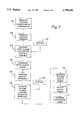
- FIG. 7 is a block diagram useful in understanding the method according to the teaching of the present invention for preventing surge in a dynamic compressor.
- FIG. 1 is a schematic diagram showing a dynamic compressor 11 with a surge prevention control system.
- the surge prevention control involves adjusting an anti-surge valve 12 which is connected to the output of the dynamic compressor 11.
- the anti-surge valve 12 is also connected to the inlet 10 of the dynamic compressor 11.
- the anti-surge valve 12 has an adjustable opening which is controlled by an electrical signal sent to a control input 112 of the anti-surge valve 12.
- the anti-surge valve 12 is opened, a portion of output flow of the dynamic compressor 11 is bypassed around the compressor 11 and returned to its inlet 10 so the flow bypassed through the anti-surge valve 12 is recycled.
- Bypassing flow around the dynamic compressor 11 increases the total flow through the dynamic compressor 11, which has the effect of moving the operating point away from the surge region. It will be appreciated that instead of recycling the gas as illustrated in FIG. 1, the flow of the dynamic compressor 11 can also be increased by simply dumping a portion of the output flow of the dynamic compressor 11 via the anti-surge valve 12.
- bypass is used herein, unless the context indicates otherwise, it is intended to encompass both the preferred form of recycling, as well as the less preferred form of dumping.
- the opening and closing of the anti-surge valve 12 should be carefully controlled.
- the valve opening is controlled by a multiple module controller 20.
- the multiple module controller 20 not only operates the anti-surge valve 12 to control the operating point of the compressor 11 when the operating point is close to the surge line, but also operates the anti-surge valve 12 to directly control the rate of approach of the operating point to the surge line when such rate of approach is high.
- the multiple module controller 20 anticipates the likelihood of surge by monitoring the rate of approach and takes corrective action by opening the anti-surge valve 12 to control the rate of approach in the event that the operating point moves rapidly toward the surge line.
- the dynamic compressor 11 has a gas inlet schematically shown at 10, and operates to compress the gas and supply the compressed gas via an output 18 to a downstream process 14.
- a plurality of sensors are disposed in the inlet 11 and outlet 18 as is conventional, and are adapted to monitor the operating conditions of the compressor.
- the sensors typically include an inlet temperature sensor 91, an inlet pressure sensor 92, a flow sensor 93, a discharge pressure sensor 94, a discharge temperature sensor 95. Other types of sensors can also be used.
- the output signals of the sensors are sent to a process measurement module 15 which processes the sensor output signals to determine the operating conditions of the compressor 11.
- the output of the process measurement module 15 is used by a control variable calculator 16, which calculates a control variable according to the measured operating conditions.
- the control variable is then used by the multiple module controller 20 to generate an output control signal, which is used by the valve positioning controller 17 to control the valve opening of the anti-surge valve 12.
- the multiple module controller 20 comprises a PID control module 21 and a rate control module 40, both of which operate to control the valve opening of the anti-surge valve 12 to prevent surge in the compressor 11 (FIG. 1).
- the PID control module 21 is optimized for controlling the position of the operating point of the dynamic compressor 11 between a predefined surge control line and the surge line so as to resist movement of the operating point into the surge region.
- FIG. 5 Digressing briefly to FIG. 5, there is shown a compressor map in which a surge line 70 divides an unstable operating region 73 (the surge region) to the left of the surge line from a stable operating region 74 to the right of the surge line 73.
- a surge control line 71 defines an operating region between the surge line 70 and surge control line 71 where the PID control module 21 is primarily tuned to control the anti-surge valve.
- a rate control module 40 is operative, regardless of the position of the operating point in the compressor map, to respond to a rapid movement of the operating point toward surge by assuming control of the anti-surge valve 12 to open the anti-surge valve 12 and reduce the rate at which the operating point is approaching the surge line 73.
- the rate control module 40 is optimized to anticipate the likelihood of surge and to directly control the rate of approach.
- the rate control module 40 will respond to a high rate of approach by opening the anti-surge valve 12 even if the operating point is still relatively far away from the surge line 73.
- the multiple module controller 20 has a control signal input 120 for receiving the control variable generated by the control variable calculator 16.
- the calculated control variable is indicative of the operating point of the dynamic compressor 11 in the compressor map.
- the control variable generally used in compressor surge control systems is defined as:
- each value of the control variable defined in this way corresponds to a parabolic curve in the compressor map.
- the position of the operating point of the compressor 11 in the map corresponding to a given value of the control variable can be uniquely determined if the actual flow rate is known.
- the control variable is received by the PID control module 21 as its process variable.
- the control variable is further sent to a derivative module 22 which operates on the control variable to produce a rate signal having a magnitude indicative of the rate of approach of the operating point to the surge line 70 (FIG. 5).
- the rate signal is then sent to the rate control module 40 as its process variable. It will be appreciated that the rate signal can indicate a motion of the operating point either towards or away from the surge region.
- the term "rate of approach" used herein refer to the speed of movement of the operation point towards the surge region.
- the PID control module 21 exerts closed loop control on the control variable to produce proportional, integral, and derivative terms and ultimately produces a first output signal for controlling the positioning of the anti-surge valve 12.
- the PID control module 21 is provided with a setpoint which corresponds to the surge control line 71 (FIG. 5), and the PID control module 21 acts to control the control variable when the value of the control variable is between the surge control line 71 and the surge line 70. In other words, the PID control module 21 acts to exert control action when the operating point of the dynamic compressor 11 assumes a position between the surge control line 71 and the surge line 70.
- the setpoint of the PID control module 21 is preferably selected to allow a chosen safety margin, typically between % 5 and 15%, between the surge line and the surge control line 71.
- the rate control module 40 is also a form of closed loop PID controller having proportional, integral, and derivative terms.
- the rate control module 40 uses the rate signal as its process variable and generates a second output signal for controlling the opening of the anti-surge valve 12 when the rate of approach exceeds the setpoint of the rate control module 40.
- the rate control module 40 In response to a high rate of approach, caused, for example, by a sudden drop of the flow rate of the compressor 11, the rate control module 40 generates an output signal to open the anti-surge valve 12 to increase the flow so as to reduce the rate of approach toward the setpoint of the rate control module 40.
- the setpoint of the rate control module 40 also functions as a threshold point so that the rate control module 40 will not open the valve if the rate of approach is below the setpoint. In this way, unnecessary opening of the anti-surge valve 12 and interference to the downstream process 14 (FIG. 1) can be minimized.
- both the PID control module 21 and the rate control module 40 generate output signals for controlling the opening of the anti-surge valve 12.
- the control operations of the PID control module 21 and the rate control module 40 are coordinated using an output signal selector 25.
- the output signal selector 25 typically has a plurality of input signals.
- the only input signals of interest are those from the PID control module 21 and the rate control module 40.
- other controllers can provide output signals for the anti-surge valve 12, and those can include open loop controllers, load sharing controllers, and the like.
- Each of the input signals is normalized to correspond to a degree of valve opening of the anti-surge valve 12.
- One of the input signals is selected by the output signal selector 25 as the output signal of the multiple module controller 20 for controlling the anti-surge valve 12.
- the output signal selector 25 is a high signal selector in the sense that it selects the input signal that corresponds to the largest valve opening among the input signals.
- the rate control module 40 and the PID control module can effectively perform their respective functions when the situation calls for either of them. For example, when the rate of approach exceeds the setpoint of the rate control module 40 but the operating point is still in the stable operation region, the rate control module 40 will be selected to open the valve 12 to prevent surge. On the other hand, if the operating point is close to the surge line but moving slowly, the PID control module 21 will be selected to control the valve opening to bring the operating point back to the surge control line. On another scenario, if the operation point is in the stable region and moving away from the surge region the rate control module will try to close the valve rapidly. Typically in such a case, the PID control module 21 will tend to close the valve at a slower pace. In such a case, the PID control module will have control of the valve and close the valve smoothly.
- a special purpose controller which takes account of the fact that the process signal for the controller is rate information, not position information.
- the controller like a conventional closed loop controller, has a process signal and a setpoint which are compared to produce an error signal the magnitude of which drives the output to zero the error signal.
- the process signal is a rate signal, and the controller is a PID, the ability to zero the error signal is lost unless special steps are taken.
- the rate control module 40 is provided with an integrator which provides an integral operation in addition to the proportional-integral-derivative terms commonly used in PID controllers.
- the rate control module 40 in the preferred embodiment is therefore an IPID controller.
- This integrator is provided so that the rate control module 40 reduces the error defined as the difference between its setpoint and its process variable, to zero.
- the integrator is necessary for that purpose because operating a conventional PID on a process variable which is a derivative of a field measured or calculated signal will provide action on the signal but will not have sufficient control response to reduce the error to zero in transient situations. For example, if the downstream process using the gas is shut down, the flow may drop continuously over a period of time of, for example, thirty seconds.
- the rate control module 40 is an IPID, is different from conventional PID controller in that it will continue to open the valve even if the process input equals the rate setpoint, i.e., if the error is zero. Such a response is due to the function of the additional integrator in the rate control module. In this way, the rate control module 40 is capable of reducing the rate error to zero.
- the effect of the integrator can be illustrated, using Laplace transformation notation as follows.
- the control variable in the preferred embodiment, is defined as: ##EQU1## where WS is the control variable, Q is the actual flow, and H is the polytropic head.
- the process variable for the rate control is defined as:
- the setpoint of the rate control is defined as
- a conventional PID has a transfer function defined as: ##EQU2##
- the output of a conventional PID when presented with the error, will have the following form: ##EQU3## It can be seen that the "integral" term is missing in such an output. This is significant from a control standpoint since it is appreciated that the integral term is the term which ultimately brings the error signal to zero in a PID controller. Without an integral term, the PID controller cannot control the derivative of a process signal to a desired setpoint, i.e., the error cannot be reduced to zero.
- the rate controller is provided with an integrator so that its transfer function has the following form: ##EQU4##
- the rate control module operates on the error, the output has the form: ##EQU5##
- I/(1+s) the "integral" term, represented by I/(1+s)
- the rate control becomes an integral-proportional-integral-derivative (IPID) type controller, instead of a conventional PID type controller.
- IPID integral-proportional-integral-derivative
- the integrator 46 is implemented by adding a derivative operator 45 in a feedback path 44 to the PID portion 47 of the rate control module 40. Incorporating the derivative function of the derivative operator 45 in the feedback path 44 emulates an integral operation, which is in addition to the "integral" term in the PID portion 47.
- the PID portion 47 of the rate control module 40 includes a proportional operator 38, an integral operator 39, and a derivative operator 41.
- the output of the integral operator 39 is processed by the derivative operator 45, and the output of the derivative operator 45 is sent to the input of the integral operator 39 via the feedback path 44.
- This arrangement of feeding the output of the integral operator 39 back to its input via the derivative operator 45 emulates an integration function and provides the transfer function described above. Such an integration function allows the error of the rate control module 40 to be reduced to zero.
- the input of the derivative operator 45 is taken at the output of the integral operator 39, and after the proportional operator 38, but before the derivative operator 41 in the PID module 47.
- the input to the derivative module 45 contains position related information.
- the process variable, which is presented to the first summer 34 contains rate information which is presented to the integrator module 39 which integrates the rate information to produce position related information.
- the derivative operator 45 thereupon notes changes in the integrated rate information, and feeds that information back to the input of the integral operator 39 by way of summer 35. It will thus be appreciated that position related information is inserted into the PID function, and it is that information which allows the modified PID (IPID) of the rate control module 40 to zero the error signal.
- IPID modified PID
- the multiple module controller 20 allows transfer between modules and the controller, and if not properly implemented, can produce substantial discontinuities in the output signal applied to the anti-surge valve 12, when switching from module to module.
- the multiple module controller 40 is provided with a tracking function whereby the controller 40 determines which of the modules is the active module in control of the anti-surge valve 12, and which are inactive. All of the modules continue to monitor their input signals, and if steps were not taken, would produce output signals which differ from module to module.
- the multiple module controller 40 is provided with tracking means for causing the inactive modules to track the output of the active module.
- the output of the output signal selector 25 is coupled to the tracking inputs of all the modules, and a tracking control line is provided for causing all of the inactive modules to track the output of the output signal selector 25.
- either of the PID control module 21 or the rate control module 40 can have control over the anti-surge valve 12 as long as its output signal is larger than that of the other.
- both the PID control module 21 and the rate control module 40 are provided with a tracking feature so that their output signals track the output signal of the output signal selector 25.
- the output signal of the output signal selector 25 is fed back to the PID control module 21 and the rate control module 40 via output tracking lines 27 and 29.
- the output signal selector 25 also has tracking control lines 26 and 28 connected to the PID control module 21 and the rate control module 40, respectively.
- the tracking control lines 26 and 28 are used for transmitting tracking control signals indicating to each of the control modules 21 and 40 whether its output signal has been selected, i.e., whether it is currently in control of the anti-surge valve 12. The control module that is not in control will then adjust its output to track the output of the output signal selector 25.
- FIG. 3 shows an example of the implementation of the tracking function of the rate control module 40 and the PID control module 21 described above.
- a switch 42 is provided to select between the output signal of the output signal selector 25 on the tracking output line 43 and the output of the derivative operator 45.
- the switch 42 is controlled to connect the output signal of the output signal selector 25 on the tracking output line 43 to the summer 35 as the input to the integral operator 39.
- Providing the output of the output signal selector 25 to the summer 35 serves to preload the integral module 39, causing the output signal of the rate control module 40 to be driven to the same level as the output signal of the active PID control module 21.
- the output signal of the rate control module 40 will be driven to the same level as the output signal of the active PID control module 21.
- their outputs will be at the same level, providing a bumpless transfer.
- the control after the switch 40 will be in response to the process input and the PID functions associated with the now-active control module.
- Adding the integrator function to the rate control module PID, and operating the rate control module 40 in parallel with the conventional PID module 21 provides a substantially enhanced control system.
- the PID control module 21 is operative when the operating point is near the surge control line 71 (FIG. 5), and in that region, its output signal will normally control.
- the rate control module 40 will produce a high output signal and take control of the anti-surge valve 12.
- the set point for the rate control module 40 can be set at a fixed level corresponding to the maximum rate of approach acceptable in the compressor system. If the rate of approach exceeds that preset value, the rate control module 40 will produce an output signal. If its output is larger than the output signal produced by the PID control module 21, it will take charge of the anti-surge valve 12 and control its degree of opening.
- the setpoint of the rate control module 40 is adjusted according to the distance between the operating point of the compressor 11 and the surge line 70 (FIG. 5). Generally, the setpoint is set high when the operating point is far from the surge line 70, and is reduced when the operating point is closer to the surge line 70. In this way, higher flow rate fluctuation can occur without triggering the rate control module 40 into action when the flow is high, thereby avoiding unnecessary opening of the anti-surge valve 12.
- the setpoint of the rate control module 40 is reduced to provide higher sensitivity when the operating point is near the surge line 70. It is important to note that the setpoint of the rate control module 40 cannot be allowed to be reduced to zero; if it were, the rate control module 40 would keep the anti-surge valve 12 fully open regardless of the steady state condition of its process variable. This condition is avoided by setting a minimum non-zero lower limit for the output of the setpoint adjuster 24.
- the proximity of the control variable to the setpoint of the PID control module 21, i.e., the difference between the control variable and the surge control line setpoint of the PID control module 21, is used as an indicator of the proximity of the operating point of the dynamic compressor 11 to the surge line 70 for the purpose of adjusting the setpoint of the rate control module 40.
- An example of the functional dependence of the setpoint of the rate control module 40 on the proximity of the control variable to the setpoint of the PID control module 21 is illustrated in FIG. 4. As shown in FIG. 4, the setpoint of the rate control module 40 is variable between a maximum value and a minimum value.
- the setpoint of the PID control module 21 When the difference between the control variable and the setpoint of the PID control module 21 is above a value indicated by the point 61, the setpoint is fixed at a maximum value indicated by the point 63. When difference between the control variable and the setpoint of the PID control module 21 is below a value indicated by the point 62, the setpoint is fixed at a non-zero minimum value indicated by the point 64. When the difference between the control variable and the setpoint of the PID control module 21 is in the range between the two points 61 and 62, the setpoint of the rate control module 40 is linearly dependent on the difference. It will be appreciated that the method of setting the setpoint of the rate control module 40 as illustrated in FIG.
- the setpoint of the rate control module 40 is adjusted by a setpoint adjuster 24 which receives a signal from the control variable calculator 16 and determines the difference between the control variable and the setpoint of the PID control module 21.
- the gain of the rate control module 40 is adjusted to regulate the dynamics of the rate control module 40 as the process conditions of the dynamic compressor 11 change.
- the flow through the anti-surge valve 12 can change significantly.
- the same amount of valve opening adjustment can have significantly different degrees of effect on the flow, depending on the process conditions of the dynamic compressor 11.
- the gain of the rate control module 40 is controlled according to the following gain function:
- P s , P d , and T d are the suction pressure, discharge pressure, and discharge temperature of the dynamic compressor 11, respectively;
- SG is the specific gravity of the gas being processed by the compressor 11;
- K is a constant which is the typical gain for system response;
- F is a function that represents the normalized change in the relationship between the valve action and flow as the process conditions change, which depends on the flow characteristics of the anti-surge valve 12.
- FIG. 6 is a block diagram showing the interrelationship of the elements for establishing the values of the gain, setpoint and process variable of the rate control module 40 in the preferred embodiment of the invention.
- a module 81 performs a process measurement to determine the operating conditions of the compressor 11.
- the result of the process measurement is used in a module 82 to calculate the control variable typically (flow) 2 /head.
- the control variable is then used in the setpoint adjuster 24 to establish the setpoint of the rate control module 40 as a function of the difference between the control variable and the setpoint of the PID control module 21.
- the process variable of the rate control module 40 is the derivative of the primary (flow) 2 /head process variable, and is determined in the derivative module 22.
- the flow characteristics of the anti-surge valve 12 are determined in module 85.
- the valve flow characteristics and the result of the process measurement are then used to normalize the response of the anti-surge valve 12 as a function of the process conditions in module 86.
- a gain constant for system response is established using the output of the module 86.
- the gain constant and the normalized process response are multiplied in module 88 to control the value of the gain of the rate control module 40.
- the output signal selector 25 receives input signals from only the PID control module 21 (FIG. 2) and the rate control module 40 (FIG. 2), so that the output signal of either of the two control modules 21 and 40 will be selected as the output signal of the output signal selector 25 for controlling the valve opening of the anti-surge valve 12 (FIG. 2).
- the setpoint for the PID control module 21 is normalized to one hundred (100.0). If the control variable has a value smaller or equal to 100.0, the PID control module 21 acts to open the anti-surge valve 12 (FIG. 2). If the control variable is larger than 100.0, the PID control module 21 acts to close the anti-surge valve 21.
- the rate control module 40 acts on the rate at which the control variable approaches the setpoint of the PID control module 21.
- the multiple module controller 20 (FIG. 2) is assumed to have a loop response time of ten (10.0) seconds.
- the setpoint of the rate control module 40 is set using the following equation: ##EQU6## for a control variable value within the range of 105.0 to 200.0, where S R is the setpoint of the rate control module 40, S PID is the setpoint of the PID control module 21, and CV is the control variable.
- the setpoint is set to a maximum of 10.0 if the control variable exceeds 200.0, and is set to a minimum of 0.5 if the control variable falls below 105.0.
- the compressor map of the dynamic compressor 11 (FIG. 1) controlled by the multiple module controller 20 is shown in FIG. 5.
- the vertical axis of compressor map is the polytropic head, and the horizontal axis is the actual flow of the dynamic compressor 11.
- the surge line 70 divides the surge region 73 and the stable operation region 74.
- a surge control line 71 which corresponds to the selected setpoint of the PID control module 21, is disposed in the stable operation region 74 at a selected safety margin from the surge line 70.
- the surge line 70 is assumed to correspond to a control variable value of 90.0.
- the points A, B, C, D, and E correspond to the control variable values of 150.0, 140.0, 130.0, 95.0, and 100.0, respectively.
- the setpoint of the rate control module 40 is 5.0.
- the rate control module 40 would not respond to such a movement because the rate is lower than its setpoint.
- the control variable drops below 140.0, and the setpoint of the rate control module 40 drops below 4.0.
- the rate control module 40 then becomes active and generates an output signal to open the anti-surge valve 12 because its setpoint has become lower than the reduction rate of the control variable.
- the PID control module 21 produces an output signal to close the anti-surge valve 12 because the control variable is still higher than the setpoint of the PID control module 21.
- the output signal of the rate control module 40 is selected by the output signal selector 25 and the rate control module 40 begins to open the anti-surge valve 12 to control the reduction rate of the control variable. It will be appreciated that due to the mathematical correspondence between the control variable and the position of the operating point on the compressor map, controlling the rate of change of the control variable is conceptually equivalent to controlling the rate of approach of the operating point to either the surge control line 71 or the surge line 70.
- the setpoint of the rate control module 40 is reduced to 3.0. If the operating point stops at point C so that the control variable is stable at 130.0, then the rate control module 40 will start to close the anti-surge valve 12. If, however, the operating point continues to move from point C to point D and that the control variable drops at a rate higher than the setpoint of the rate control module 40, the rate control module 40 will continue to open the anti-surge valve 12 in order to control the reduction rate of the control variable.
- the control variable is reduced below 100.0, the setpoint of the PID control module 21.
- the PID control module 21 then becomes active and generates an output signal to open the anti-surge valve 12 in order to control the control variable.
- the output signal of the PID control module 21 is compared to the output signal of the rate control module 40, and the larger of the two output signals will be selected to control the anti-surge valve 12. If the operating point stops at point E so that it is no longer approaching the surge line 70, the rate of change of the control variable is below the setpoint of the rate control module 40, which is 0.5 at point E.
- the rate control module 40 then generates an output signal to close the anti-surge valve 12.
- the PID control module 21 generates an output signal to open the anti-surge valve 12 in order to move the control variable toward its setpoint of 100.0. In this situation, the PID control module 21 will have control of the anti-surge valve 12.
- the switching of control of the anti-surge valve 12 between the PID control module 21 and the rate control module 40 depends on how fast the control variable changes, the value of the control variable, and the tuning of the rate control module 40 and the PID control module 21, as well as the system dynamics. If the operating point is moving slowly but is left of the surge control line 71, then the PID control module 21 is likely to gain control of the anti-surge valve 12. On the other hand, if the operating point is very close to the surge control line 71 but is moving toward the surge line 70 at a sufficiently high rate, then the rate control module 40 is likely to gain control of the anti-surge valve 12.
- an anti-surge valve 12 (FIG. 1) is connected to the dynamic compressor 11.
- the valve opening of the anti-surge valve 12 is controllably adjusted to bypass the output flow around the dynamic compressor 11 to increase the flow through the dynamic compressor 11.
- the process conditions, such as flow, pressure, and temperature, etc., of the compressor 11 are measured (step 102).
- the result of the process measurement is used to produce a control variable indicative of the operating point of the compressor 11 in its compressor map (step 103).
- a step 105 exercises closed loop PID control on the control variable 103.
- the step has a setpoint, schematically indicated at 104, which determines the point to which the process variable is to be controlled.
- the setpoint 104 is the surge control line 71 (FIG. 5)
- the step 105 exerts control of the anti-surge valve primarily in the region between the surge control line 71 and the surge line 70 (FIG. 5).
- the PID control function is used to generate a first output signal (step 106) which controls the output of the anti-surge valve 12.
- step 107 the rate of approach of the operating point towards surge is monitored.
- the same signal which serves as the process input for the control operation in step 105 is used as an input to step 107, and step 107 simply produces the time derivative of the process signal. That time derivative serves as an indicator of the rate of approach of the compressor operating point to the surge line 70 or the surge control line 71.
- the rate of approach is directly controlled by performing a second closed loop PID operation on the rate of approach (step 108).
- the PID of step 108 also has a setpoint, identified schematically at 108', which is used with the rate signal as a process variable to produce an error signal, and to generate an output signal from the PID of step 108 capable of controlling the anti-surge valve 21.
- the setpoint 108' is simply a fixed level indicating the maximum allowable rate of approach of the operating point to the surge control line.
- the setpoint adjusting module 24 of FIG. 2 is preferably utilized.
- the step 108 utilizes a PID control in combination with an integrator as described in detail above to produce an output signal capable of reducing the error between the setpoint and the process variable to zero.
- the output signal is a measure of the degree of opening of the anti-surge valve demanded by the rate control PID, and the generation of that output signal is illustrated by the block 109.
- a selection between first and second output signals is then made (step 110), and the output signal corresponding to larger opening of the anti-surge valve 12 is selected to control the valve opening of the anti-surge valve 12 (step 111).
- the first PID operation of step 105 will have control of the anti-surge valve 12 to control the control variable.
- the second PID operation of step 108 will produce a larger output signal than that of the first PID control.
- the second PID operation takes control of the anti-surge valve 12 and opens it to control the rate of approach.
Landscapes
- Engineering & Computer Science (AREA)
- Life Sciences & Earth Sciences (AREA)
- Sustainable Development (AREA)
- Mechanical Engineering (AREA)
- General Engineering & Computer Science (AREA)
- Physics & Mathematics (AREA)
- General Physics & Mathematics (AREA)
- Automation & Control Theory (AREA)
- Control Of Positive-Displacement Air Blowers (AREA)
- Feedback Control In General (AREA)
- Control Of Positive-Displacement Pumps (AREA)
Priority Applications (1)
| Application Number | Priority Date | Filing Date | Title |
|---|---|---|---|
| US08/802,781 US5798941A (en) | 1996-01-02 | 1997-02-18 | Surge prevention control system for dynamic compressors |
Applications Claiming Priority (2)
| Application Number | Priority Date | Filing Date | Title |
|---|---|---|---|
| US58208396A | 1996-01-02 | 1996-01-02 | |
| US08/802,781 US5798941A (en) | 1996-01-02 | 1997-02-18 | Surge prevention control system for dynamic compressors |
Related Parent Applications (1)
| Application Number | Title | Priority Date | Filing Date |
|---|---|---|---|
| US58208396A Continuation | 1996-01-02 | 1996-01-02 |
Publications (1)
| Publication Number | Publication Date |
|---|---|
| US5798941A true US5798941A (en) | 1998-08-25 |
Family
ID=24327770
Family Applications (1)
| Application Number | Title | Priority Date | Filing Date |
|---|---|---|---|
| US08/802,781 Expired - Lifetime US5798941A (en) | 1996-01-02 | 1997-02-18 | Surge prevention control system for dynamic compressors |
Country Status (7)
| Country | Link |
|---|---|
| US (1) | US5798941A (de) |
| EP (1) | EP0871853B1 (de) |
| JP (1) | JP3205561B2 (de) |
| CN (1) | CN1136485C (de) |
| CA (1) | CA2231443C (de) |
| DE (1) | DE69727044T2 (de) |
| WO (1) | WO1997024591A1 (de) |
Cited By (61)
| Publication number | Priority date | Publication date | Assignee | Title |
|---|---|---|---|---|
| US5967742A (en) * | 1997-12-23 | 1999-10-19 | Compressor Controls Corporation | Method and apparatus for preventing surge while taking a turbocompressor off-line from a parallel configuration |
| US6468046B1 (en) * | 2000-09-18 | 2002-10-22 | Caterpillar Inc | Apparatus and method for controlling a discharge pressure of a variable displacement hydraulic pump |
| US6503048B1 (en) * | 2001-08-27 | 2003-01-07 | Compressor Controls Corporation | Method and apparatus for estimating flow in compressors with sidestreams |
| US6602057B2 (en) | 2001-10-01 | 2003-08-05 | Dresser-Rand Company | Management and optimization of load sharing between multiple compressor trains for controlling a main process gas variable |
| US6823254B2 (en) * | 2003-03-28 | 2004-11-23 | Honeywell International, Inc. | Method and system for turbomachinery surge detection |
| US20040261407A1 (en) * | 2003-06-30 | 2004-12-30 | Hongliu Du | Method and apparatus for controlling a hydraulic motor |
| US20050022589A1 (en) * | 2003-07-28 | 2005-02-03 | Hongliu Du | Hydraulic system health indicator |
| US20050160749A1 (en) * | 2004-01-23 | 2005-07-28 | Shaffer Dennis L. | Enhanced manual start/stop sequencing controls for a steam turbine powered chiller unit |
| US20060067833A1 (en) * | 2004-09-22 | 2006-03-30 | Hamilton Sundstrand | Integral add heat and surge control valve for compressor |
| US7094019B1 (en) * | 2004-05-17 | 2006-08-22 | Continuous Control Solutions, Inc. | System and method of surge limit control for turbo compressors |
| US20070110587A1 (en) * | 2003-08-28 | 2007-05-17 | Kazuko Takeshita | Control unit for compressor |
| US7328587B2 (en) | 2004-01-23 | 2008-02-12 | York International Corporation | Integrated adaptive capacity control for a steam turbine powered chiller unit |
| US20080085180A1 (en) * | 2006-10-06 | 2008-04-10 | Vaportech Energy Services Inc. | Variable capacity natural gas compressor |
| US7412841B2 (en) * | 2003-12-18 | 2008-08-19 | Mitsubishi Heavy Industries, Ltd. | Turbo chiller, compressor therefor, and control method therefor |
| US7421854B2 (en) | 2004-01-23 | 2008-09-09 | York International Corporation | Automatic start/stop sequencing controls for a steam turbine powered chiller unit |
| US20090140444A1 (en) * | 2007-11-29 | 2009-06-04 | Total Separation Solutions, Llc | Compressed gas system useful for producing light weight drilling fluids |
| US7878006B2 (en) | 2004-04-27 | 2011-02-01 | Emerson Climate Technologies, Inc. | Compressor diagnostic and protection system and method |
| US20110093133A1 (en) * | 2009-10-20 | 2011-04-21 | Johnson Controls Technology Company | Controllers and methods for providing computerized generation and use of a three dimensional surge map for control of chillers |
| EP2386762A1 (de) * | 2010-05-11 | 2011-11-16 | Krishnan Narayanan | Verfahren zum Schutz von Verdichterpumpen für einen dynamischen Kompressor mithilfe eines die Verdichterpumpen charakterisierenden Parameters |
| US20120014812A1 (en) * | 2009-03-30 | 2012-01-19 | Paul Musgrave Blaiklock | Compressor Surge Control System and Method |
| US20120048387A1 (en) * | 2010-08-31 | 2012-03-01 | Daniele Galeotti | Device and method for detecting a surge in a compressor and relocating a surge margin |
| CN102392813A (zh) * | 2011-06-10 | 2012-03-28 | 辽宁华兴森威科技发展有限公司 | 压缩机组转速调节控制系统 |
| US8160827B2 (en) | 2007-11-02 | 2012-04-17 | Emerson Climate Technologies, Inc. | Compressor sensor module |
| US8393169B2 (en) | 2007-09-19 | 2013-03-12 | Emerson Climate Technologies, Inc. | Refrigeration monitoring system and method |
| US20130112277A1 (en) * | 2011-11-08 | 2013-05-09 | Dresser-Rand Company | Compact turbomachine system with improved slug flow handling |
| NO333438B1 (no) * | 2010-07-14 | 2013-06-03 | Statoil Asa | Fremgangsmate og apparat for sammensetningsbasert kompressorkontroll og ytelsesovervaking. |
| US8590325B2 (en) | 2006-07-19 | 2013-11-26 | Emerson Climate Technologies, Inc. | Protection and diagnostic module for a refrigeration system |
| US20140238742A1 (en) * | 2013-02-27 | 2014-08-28 | Skf Lubrication Systems Germany Ag | Device for supplying lubricant to a lubrication point in a machine |
| US8964338B2 (en) | 2012-01-11 | 2015-02-24 | Emerson Climate Technologies, Inc. | System and method for compressor motor protection |
| US8974573B2 (en) | 2004-08-11 | 2015-03-10 | Emerson Climate Technologies, Inc. | Method and apparatus for monitoring a refrigeration-cycle system |
| US9097447B2 (en) | 2012-07-25 | 2015-08-04 | Johnson Controls Technology Company | Methods and controllers for providing a surge map for the monitoring and control of chillers |
| US9133850B2 (en) | 2011-01-13 | 2015-09-15 | Energy Control Technologies, Inc. | Method for preventing surge in a dynamic compressor using adaptive preventer control system and adaptive safety margin |
| US9140728B2 (en) | 2007-11-02 | 2015-09-22 | Emerson Climate Technologies, Inc. | Compressor sensor module |
| US20150300347A1 (en) * | 2012-11-07 | 2015-10-22 | Nuovo Pignone Srl | A method for operating a compressor in case of failure of one or more measure signal |
| US20150308442A1 (en) * | 2014-04-24 | 2015-10-29 | Control Components, Inc. | Dead time reducer for piston actuator |
| US20160040604A1 (en) * | 2013-03-14 | 2016-02-11 | United Technologies Corporation | Pressure Sensor Noise Filter Prior to Surge Detection for a Gas Turbine Engine |
| US20160047338A1 (en) * | 2014-08-14 | 2016-02-18 | Ford Global Technologies, Llc | Methods and systems for surge control |
| US9285802B2 (en) | 2011-02-28 | 2016-03-15 | Emerson Electric Co. | Residential solutions HVAC monitoring and diagnosis |
| US9310439B2 (en) | 2012-09-25 | 2016-04-12 | Emerson Climate Technologies, Inc. | Compressor having a control and diagnostic module |
| US9310094B2 (en) | 2007-07-30 | 2016-04-12 | Emerson Climate Technologies, Inc. | Portable method and apparatus for monitoring refrigerant-cycle systems |
| US9480177B2 (en) | 2012-07-27 | 2016-10-25 | Emerson Climate Technologies, Inc. | Compressor protection module |
| US9551504B2 (en) | 2013-03-15 | 2017-01-24 | Emerson Electric Co. | HVAC system remote monitoring and diagnosis |
| US9638436B2 (en) | 2013-03-15 | 2017-05-02 | Emerson Electric Co. | HVAC system remote monitoring and diagnosis |
| US9765979B2 (en) | 2013-04-05 | 2017-09-19 | Emerson Climate Technologies, Inc. | Heat-pump system with refrigerant charge diagnostics |
| US20170284410A1 (en) * | 2016-04-01 | 2017-10-05 | Fisher-Rosemount Systems, Inc. | Methods and apparatus for detecting and preventing compressor surge |
| US9823632B2 (en) | 2006-09-07 | 2017-11-21 | Emerson Climate Technologies, Inc. | Compressor data module |
| US10254719B2 (en) * | 2015-09-18 | 2019-04-09 | Statistics & Control, Inc. | Method and apparatus for surge prevention control of multistage compressor having one surge valve and at least one flow measuring device |
| US10260514B2 (en) * | 2016-03-11 | 2019-04-16 | Hanwha Power Systems Co., Ltd | System and method of controlling compressor |
| US10480422B2 (en) * | 2014-07-31 | 2019-11-19 | Mitsubishi Heavy Industries Compressor Corporation | Control device and control method for a fuel gas supply system |
| US10488090B2 (en) | 2013-03-15 | 2019-11-26 | Emerson Climate Technologies, Inc. | System for refrigerant charge verification |
| WO2020009825A1 (en) * | 2018-07-02 | 2020-01-09 | Cummins Inc. | Compressor surge control |
| US20200063651A1 (en) * | 2018-08-27 | 2020-02-27 | Garrett Transportation I Inc. | Method and system for controlling a variable-geometry compressor |
| US20200156675A1 (en) * | 2018-11-15 | 2020-05-21 | Transportation Ip Holdings, Llc | System and methods for detecting surge in an engine system |
| US10677149B2 (en) | 2016-03-08 | 2020-06-09 | Mitsubishi Heavy Industries Engine & Turbocharger, Ltd. | Surge avoidance control method and surge avoidance control device for exhaust turbine turbocharger |
| US10900492B2 (en) | 2010-05-11 | 2021-01-26 | Energy Control Technologies, Inc. | Method of anti-surge protection for a dynamic compressor using a surge parameter |
| CN114278603A (zh) * | 2021-12-27 | 2022-04-05 | 浙江中控技术股份有限公司 | 一种压缩机控制系统、方法、装置、设备及存储介质 |
| US20220170413A1 (en) * | 2020-12-02 | 2022-06-02 | Ford Global Technologies, Llc | Method of controlling a turbocharger |
| US11578727B2 (en) | 2020-09-17 | 2023-02-14 | Compressor Controls Llc | Methods and system for control of compressors with both variable speed and guide vanes position |
| WO2023122501A1 (en) * | 2021-12-22 | 2023-06-29 | Uop Llc | Processes and apparatuses for operating a gas compressor |
| CN116357605A (zh) * | 2022-11-23 | 2023-06-30 | 上海维尔泰克螺杆机械有限公司 | 离心式空气压缩机喘振控制方法、系统、电子设备及存储介质 |
| CN116519181A (zh) * | 2023-06-15 | 2023-08-01 | 中国科学院工程热物理研究所 | 一种用于测量旋转机械功率的方法及系统 |
Families Citing this family (9)
| Publication number | Priority date | Publication date | Assignee | Title |
|---|---|---|---|---|
| CN101664848B (zh) * | 2009-09-28 | 2012-10-03 | 洛阳市洛凌轴承科技股份有限公司 | 一种热剪切模具的剪切刃堆焊工艺 |
| JP5634907B2 (ja) | 2011-02-10 | 2014-12-03 | 株式会社日立製作所 | 圧縮機の制御装置及び制御方法 |
| CN102182700B (zh) * | 2011-05-19 | 2013-08-21 | 哈尔滨工业大学 | 涡轮增压系统压气机风量分配控制的喘振保护方法及实现该方法的喘振保护装置 |
| US9157446B2 (en) | 2013-01-31 | 2015-10-13 | Danfoss A/S | Centrifugal compressor with extended operating range |
| CN105443348A (zh) * | 2015-12-23 | 2016-03-30 | 上海金自天正信息技术有限公司 | 气体压缩机系统 |
| EP3411596B1 (de) | 2016-02-04 | 2023-11-01 | Danfoss A/S | Aktive pumpregelung in zentrifugalverdichtern mit mikrostrahlinjektion |
| IT201700100704A1 (it) * | 2017-09-08 | 2019-03-08 | Nuovo Pignone Tecnologie Srl | Sistema di controllo per un compressore con sottosistema basato sulla pressione, impianto di sintesi e metodo di controllo / control system for a compressor with pressure-based subsystem, synthesis plant and control method |
| IT201700100734A1 (it) * | 2017-09-08 | 2019-03-08 | Nuovo Pignone Tecnologie Srl | Sistema di controllo per un compressore con sottosistema basato sulla velocita’, impianto di sintesi e metodo di controllo / control system for a compressor with speed-based subsystem, synthesis plant and control method |
| US20240254926A1 (en) * | 2023-01-26 | 2024-08-01 | General Electric Company | Engine casing waste heat recirculation loop and associated method |
Citations (12)
| Publication number | Priority date | Publication date | Assignee | Title |
|---|---|---|---|---|
| US4142838A (en) * | 1977-12-01 | 1979-03-06 | Compressor Controls Corporation | Method and apparatus for preventing surge in a dynamic compressor |
| US4156578A (en) * | 1977-08-02 | 1979-05-29 | Agar Instrumentation Incorporated | Control of centrifugal compressors |
| US4486142A (en) * | 1977-12-01 | 1984-12-04 | Naum Staroselsky | Method of automatic limitation for a controlled variable in a multivariable system |
| US4697980A (en) * | 1984-08-20 | 1987-10-06 | The Babcock & Wilcox Company | Adaptive gain compressor surge control system |
| US4831534A (en) * | 1985-12-18 | 1989-05-16 | Man Gutehoffnungshuette Gmbh | Method and apparatus for controlling turbocompressors to prevent |
| US4944652A (en) * | 1988-02-18 | 1990-07-31 | Man Gutehoffnungshutte Gmbh | Process and device for the control of turbo compressors |
| US4949276A (en) * | 1988-10-26 | 1990-08-14 | Compressor Controls Corp. | Method and apparatus for preventing surge in a dynamic compressor |
| US4971516A (en) * | 1988-05-04 | 1990-11-20 | Exxon Research & Engineering Company | Surge control in compressors |
| US5242263A (en) * | 1990-09-19 | 1993-09-07 | Framatome | Device for the control of anti-surge of a compressor |
| US5306116A (en) * | 1992-04-10 | 1994-04-26 | Ingersoll-Rand Company | Surge control and recovery for a centrifugal compressor |
| US5347467A (en) * | 1992-06-22 | 1994-09-13 | Compressor Controls Corporation | Load sharing method and apparatus for controlling a main gas parameter of a compressor station with multiple dynamic compressors |
| US5508943A (en) * | 1994-04-07 | 1996-04-16 | Compressor Controls Corporation | Method and apparatus for measuring the distance of a turbocompressor's operating point to the surge limit interface |
Family Cites Families (2)
| Publication number | Priority date | Publication date | Assignee | Title |
|---|---|---|---|---|
| JPS608497A (ja) * | 1983-06-29 | 1985-01-17 | Hitachi Ltd | 多段圧縮機の容量調節装置 |
| US4991389A (en) * | 1989-04-21 | 1991-02-12 | United Technologies Corporation | Bleed modulation for transient engine operation |
-
1997
- 1997-01-02 CA CA002231443A patent/CA2231443C/en not_active Expired - Fee Related
- 1997-01-02 DE DE69727044T patent/DE69727044T2/de not_active Expired - Lifetime
- 1997-01-02 EP EP97901917A patent/EP0871853B1/de not_active Expired - Lifetime
- 1997-01-02 CN CNB971925259A patent/CN1136485C/zh not_active Expired - Lifetime
- 1997-01-02 WO PCT/US1997/000111 patent/WO1997024591A1/en not_active Ceased
- 1997-01-02 JP JP52462797A patent/JP3205561B2/ja not_active Expired - Lifetime
- 1997-02-18 US US08/802,781 patent/US5798941A/en not_active Expired - Lifetime
Patent Citations (12)
| Publication number | Priority date | Publication date | Assignee | Title |
|---|---|---|---|---|
| US4156578A (en) * | 1977-08-02 | 1979-05-29 | Agar Instrumentation Incorporated | Control of centrifugal compressors |
| US4142838A (en) * | 1977-12-01 | 1979-03-06 | Compressor Controls Corporation | Method and apparatus for preventing surge in a dynamic compressor |
| US4486142A (en) * | 1977-12-01 | 1984-12-04 | Naum Staroselsky | Method of automatic limitation for a controlled variable in a multivariable system |
| US4697980A (en) * | 1984-08-20 | 1987-10-06 | The Babcock & Wilcox Company | Adaptive gain compressor surge control system |
| US4831534A (en) * | 1985-12-18 | 1989-05-16 | Man Gutehoffnungshuette Gmbh | Method and apparatus for controlling turbocompressors to prevent |
| US4944652A (en) * | 1988-02-18 | 1990-07-31 | Man Gutehoffnungshutte Gmbh | Process and device for the control of turbo compressors |
| US4971516A (en) * | 1988-05-04 | 1990-11-20 | Exxon Research & Engineering Company | Surge control in compressors |
| US4949276A (en) * | 1988-10-26 | 1990-08-14 | Compressor Controls Corp. | Method and apparatus for preventing surge in a dynamic compressor |
| US5242263A (en) * | 1990-09-19 | 1993-09-07 | Framatome | Device for the control of anti-surge of a compressor |
| US5306116A (en) * | 1992-04-10 | 1994-04-26 | Ingersoll-Rand Company | Surge control and recovery for a centrifugal compressor |
| US5347467A (en) * | 1992-06-22 | 1994-09-13 | Compressor Controls Corporation | Load sharing method and apparatus for controlling a main gas parameter of a compressor station with multiple dynamic compressors |
| US5508943A (en) * | 1994-04-07 | 1996-04-16 | Compressor Controls Corporation | Method and apparatus for measuring the distance of a turbocompressor's operating point to the surge limit interface |
Non-Patent Citations (15)
| Title |
|---|
| "Basic TurboCompressor Control and Protection", 36 Turbomachinery International, Jul./Aug. 1995. |
| "Benefits of the Series 3 Control System" from Series 3 Antisurge Controller Manual No. IM31 of Woodward Governor Co. (No date). |
| "Compressor Surge Prevention" by Larry McLeister in Turbomachinery Control Conference 1995. (No date with month). |
| "How to Cope with the High Speed of Approaching Surge", p. 7, Turbomachinery Maintenance, Jul. 1988. |
| Basic TurboCompressor Control and Protection , 36 Turbomachinery International, Jul./Aug. 1995. * |
| Benefits of the Series 3 Control System from Series 3 Antisurge Controller Manual No. IM31 of Woodward Governor Co. (No date). * |
| Compressor Surge Prevention by Larry McLeister in Turbomachinery Control Conference 1995. (No date with month). * |
| Excerpts from "Anti-Surge Control" manual of Dresser-Rand Control Systems. (No date). |
| Excerpts from Anti Surge Control manual of Dresser Rand Control Systems. (No date). * |
| How to Cope with the High Speed of Approaching Surge , p. 7, Turbomachinery Maintenance, Jul. 1988. * |
| Pp. 1, 13 16 and 18 of Compressor Antisurge Control manual of Tri Sen Co., Sep. 1993. * |
| Pp. 1, 13-16 and 18 of "Compressor Antisurge Control" manual of Tri-Sen Co., Sep. 1993. |
| Pp. 3&4 from the Steward & Stevenson Standard Control Manual for GE LM2500 turbine engine, prepared by Woodward Governor Co. (No date). * |
| Pp. 364 370 of Manual 80010 entitled Programming Manual Oriented Editor , Prepared by Woodward Governor Co. for internal use. (No date). * |
| Pp. 364-370 of Manual 80010 entitled "Programming Manual Oriented Editor", Prepared by Woodward Governor Co. for internal use. (No date). |
Cited By (120)
| Publication number | Priority date | Publication date | Assignee | Title |
|---|---|---|---|---|
| US5967742A (en) * | 1997-12-23 | 1999-10-19 | Compressor Controls Corporation | Method and apparatus for preventing surge while taking a turbocompressor off-line from a parallel configuration |
| US6468046B1 (en) * | 2000-09-18 | 2002-10-22 | Caterpillar Inc | Apparatus and method for controlling a discharge pressure of a variable displacement hydraulic pump |
| US6503048B1 (en) * | 2001-08-27 | 2003-01-07 | Compressor Controls Corporation | Method and apparatus for estimating flow in compressors with sidestreams |
| US6602057B2 (en) | 2001-10-01 | 2003-08-05 | Dresser-Rand Company | Management and optimization of load sharing between multiple compressor trains for controlling a main process gas variable |
| US6823254B2 (en) * | 2003-03-28 | 2004-11-23 | Honeywell International, Inc. | Method and system for turbomachinery surge detection |
| US20040261407A1 (en) * | 2003-06-30 | 2004-12-30 | Hongliu Du | Method and apparatus for controlling a hydraulic motor |
| US6848254B2 (en) | 2003-06-30 | 2005-02-01 | Caterpillar Inc. | Method and apparatus for controlling a hydraulic motor |
| US20050022589A1 (en) * | 2003-07-28 | 2005-02-03 | Hongliu Du | Hydraulic system health indicator |
| US7043975B2 (en) | 2003-07-28 | 2006-05-16 | Caterpillar Inc | Hydraulic system health indicator |
| US20060162439A1 (en) * | 2003-07-28 | 2006-07-27 | Hongliu Du | Hydraulic system health indicator |
| US7204138B2 (en) | 2003-07-28 | 2007-04-17 | Caterpillar Inc | Hydraulic system health indicator |
| US7556473B2 (en) * | 2003-08-28 | 2009-07-07 | Mitsubishi Heavy Industries, Ltd. | Control unit for compressor |
| US20070110587A1 (en) * | 2003-08-28 | 2007-05-17 | Kazuko Takeshita | Control unit for compressor |
| US7412841B2 (en) * | 2003-12-18 | 2008-08-19 | Mitsubishi Heavy Industries, Ltd. | Turbo chiller, compressor therefor, and control method therefor |
| US7421854B2 (en) | 2004-01-23 | 2008-09-09 | York International Corporation | Automatic start/stop sequencing controls for a steam turbine powered chiller unit |
| US7328587B2 (en) | 2004-01-23 | 2008-02-12 | York International Corporation | Integrated adaptive capacity control for a steam turbine powered chiller unit |
| US7421853B2 (en) | 2004-01-23 | 2008-09-09 | York International Corporation | Enhanced manual start/stop sequencing controls for a stream turbine powered chiller unit |
| US20050160749A1 (en) * | 2004-01-23 | 2005-07-28 | Shaffer Dennis L. | Enhanced manual start/stop sequencing controls for a steam turbine powered chiller unit |
| US9121407B2 (en) | 2004-04-27 | 2015-09-01 | Emerson Climate Technologies, Inc. | Compressor diagnostic and protection system and method |
| US9669498B2 (en) | 2004-04-27 | 2017-06-06 | Emerson Climate Technologies, Inc. | Compressor diagnostic and protection system and method |
| US10335906B2 (en) | 2004-04-27 | 2019-07-02 | Emerson Climate Technologies, Inc. | Compressor diagnostic and protection system and method |
| US7878006B2 (en) | 2004-04-27 | 2011-02-01 | Emerson Climate Technologies, Inc. | Compressor diagnostic and protection system and method |
| US7905098B2 (en) | 2004-04-27 | 2011-03-15 | Emerson Climate Technologies, Inc. | Compressor diagnostic and protection system and method |
| US8474278B2 (en) | 2004-04-27 | 2013-07-02 | Emerson Climate Technologies, Inc. | Compressor diagnostic and protection system and method |
| US7094019B1 (en) * | 2004-05-17 | 2006-08-22 | Continuous Control Solutions, Inc. | System and method of surge limit control for turbo compressors |
| US9690307B2 (en) | 2004-08-11 | 2017-06-27 | Emerson Climate Technologies, Inc. | Method and apparatus for monitoring refrigeration-cycle systems |
| US9046900B2 (en) | 2004-08-11 | 2015-06-02 | Emerson Climate Technologies, Inc. | Method and apparatus for monitoring refrigeration-cycle systems |
| US9017461B2 (en) | 2004-08-11 | 2015-04-28 | Emerson Climate Technologies, Inc. | Method and apparatus for monitoring a refrigeration-cycle system |
| US8974573B2 (en) | 2004-08-11 | 2015-03-10 | Emerson Climate Technologies, Inc. | Method and apparatus for monitoring a refrigeration-cycle system |
| US9023136B2 (en) | 2004-08-11 | 2015-05-05 | Emerson Climate Technologies, Inc. | Method and apparatus for monitoring a refrigeration-cycle system |
| US9304521B2 (en) | 2004-08-11 | 2016-04-05 | Emerson Climate Technologies, Inc. | Air filter monitoring system |
| US9021819B2 (en) | 2004-08-11 | 2015-05-05 | Emerson Climate Technologies, Inc. | Method and apparatus for monitoring a refrigeration-cycle system |
| US10558229B2 (en) | 2004-08-11 | 2020-02-11 | Emerson Climate Technologies Inc. | Method and apparatus for monitoring refrigeration-cycle systems |
| US9086704B2 (en) | 2004-08-11 | 2015-07-21 | Emerson Climate Technologies, Inc. | Method and apparatus for monitoring a refrigeration-cycle system |
| US9081394B2 (en) | 2004-08-11 | 2015-07-14 | Emerson Climate Technologies, Inc. | Method and apparatus for monitoring a refrigeration-cycle system |
| US20060067833A1 (en) * | 2004-09-22 | 2006-03-30 | Hamilton Sundstrand | Integral add heat and surge control valve for compressor |
| US9885507B2 (en) | 2006-07-19 | 2018-02-06 | Emerson Climate Technologies, Inc. | Protection and diagnostic module for a refrigeration system |
| US8590325B2 (en) | 2006-07-19 | 2013-11-26 | Emerson Climate Technologies, Inc. | Protection and diagnostic module for a refrigeration system |
| US9823632B2 (en) | 2006-09-07 | 2017-11-21 | Emerson Climate Technologies, Inc. | Compressor data module |
| US20080085180A1 (en) * | 2006-10-06 | 2008-04-10 | Vaportech Energy Services Inc. | Variable capacity natural gas compressor |
| US9310094B2 (en) | 2007-07-30 | 2016-04-12 | Emerson Climate Technologies, Inc. | Portable method and apparatus for monitoring refrigerant-cycle systems |
| US10352602B2 (en) | 2007-07-30 | 2019-07-16 | Emerson Climate Technologies, Inc. | Portable method and apparatus for monitoring refrigerant-cycle systems |
| US9651286B2 (en) | 2007-09-19 | 2017-05-16 | Emerson Climate Technologies, Inc. | Refrigeration monitoring system and method |
| US8393169B2 (en) | 2007-09-19 | 2013-03-12 | Emerson Climate Technologies, Inc. | Refrigeration monitoring system and method |
| US8335657B2 (en) | 2007-11-02 | 2012-12-18 | Emerson Climate Technologies, Inc. | Compressor sensor module |
| US9140728B2 (en) | 2007-11-02 | 2015-09-22 | Emerson Climate Technologies, Inc. | Compressor sensor module |
| US8160827B2 (en) | 2007-11-02 | 2012-04-17 | Emerson Climate Technologies, Inc. | Compressor sensor module |
| US10458404B2 (en) | 2007-11-02 | 2019-10-29 | Emerson Climate Technologies, Inc. | Compressor sensor module |
| US9194894B2 (en) | 2007-11-02 | 2015-11-24 | Emerson Climate Technologies, Inc. | Compressor sensor module |
| US20090140444A1 (en) * | 2007-11-29 | 2009-06-04 | Total Separation Solutions, Llc | Compressed gas system useful for producing light weight drilling fluids |
| EP2414748A4 (de) * | 2009-03-30 | 2018-03-21 | TMEIC Corporation | System und verfahren zur überspannungsregelung bei einem verdichter |
| US9328949B2 (en) * | 2009-03-30 | 2016-05-03 | Tmeic Corporation | Compressor surge control system and method |
| US20120014812A1 (en) * | 2009-03-30 | 2012-01-19 | Paul Musgrave Blaiklock | Compressor Surge Control System and Method |
| US8726678B2 (en) | 2009-10-20 | 2014-05-20 | Johnson Controls Technology Company | Controllers and methods for providing computerized generation and use of a three dimensional surge map for control of chillers |
| US20110093133A1 (en) * | 2009-10-20 | 2011-04-21 | Johnson Controls Technology Company | Controllers and methods for providing computerized generation and use of a three dimensional surge map for control of chillers |
| US10900492B2 (en) | 2010-05-11 | 2021-01-26 | Energy Control Technologies, Inc. | Method of anti-surge protection for a dynamic compressor using a surge parameter |
| EP2386762A1 (de) * | 2010-05-11 | 2011-11-16 | Krishnan Narayanan | Verfahren zum Schutz von Verdichterpumpen für einen dynamischen Kompressor mithilfe eines die Verdichterpumpen charakterisierenden Parameters |
| US20120100013A9 (en) * | 2010-05-11 | 2012-04-26 | Krishnan Narayanan | Method of surge protection for a dynamic compressor using a surge parameter |
| NO333438B1 (no) * | 2010-07-14 | 2013-06-03 | Statoil Asa | Fremgangsmate og apparat for sammensetningsbasert kompressorkontroll og ytelsesovervaking. |
| US9416790B2 (en) | 2010-07-14 | 2016-08-16 | Statoil Asa | Method and apparatus for composition based compressor control and performance monitoring |
| US20120048387A1 (en) * | 2010-08-31 | 2012-03-01 | Daniele Galeotti | Device and method for detecting a surge in a compressor and relocating a surge margin |
| US9091274B2 (en) * | 2010-08-31 | 2015-07-28 | Nuovo Pignone S.P.A. | Device and method for detecting a surge in a compressor and relocating a surge margin |
| US9133850B2 (en) | 2011-01-13 | 2015-09-15 | Energy Control Technologies, Inc. | Method for preventing surge in a dynamic compressor using adaptive preventer control system and adaptive safety margin |
| US10859087B2 (en) | 2011-01-13 | 2020-12-08 | Energy Control Technologies, Inc. | Method for preventing surge in a dynamic compressor using adaptive preventer control system and adaptive safety margin |
| US10884403B2 (en) | 2011-02-28 | 2021-01-05 | Emerson Electric Co. | Remote HVAC monitoring and diagnosis |
| US9703287B2 (en) | 2011-02-28 | 2017-07-11 | Emerson Electric Co. | Remote HVAC monitoring and diagnosis |
| US9285802B2 (en) | 2011-02-28 | 2016-03-15 | Emerson Electric Co. | Residential solutions HVAC monitoring and diagnosis |
| US10234854B2 (en) | 2011-02-28 | 2019-03-19 | Emerson Electric Co. | Remote HVAC monitoring and diagnosis |
| CN102392813B (zh) * | 2011-06-10 | 2015-10-14 | 辽宁华兴森威科技发展有限公司 | 压缩机组转速调节控制系统 |
| CN102392813A (zh) * | 2011-06-10 | 2012-03-28 | 辽宁华兴森威科技发展有限公司 | 压缩机组转速调节控制系统 |
| US9303658B2 (en) * | 2011-11-08 | 2016-04-05 | Dresser-Rand Company | Compact turbomachine system with improved slug flow handling |
| US20130112277A1 (en) * | 2011-11-08 | 2013-05-09 | Dresser-Rand Company | Compact turbomachine system with improved slug flow handling |
| US8964338B2 (en) | 2012-01-11 | 2015-02-24 | Emerson Climate Technologies, Inc. | System and method for compressor motor protection |
| US9590413B2 (en) | 2012-01-11 | 2017-03-07 | Emerson Climate Technologies, Inc. | System and method for compressor motor protection |
| US9876346B2 (en) | 2012-01-11 | 2018-01-23 | Emerson Climate Technologies, Inc. | System and method for compressor motor protection |
| US9097447B2 (en) | 2012-07-25 | 2015-08-04 | Johnson Controls Technology Company | Methods and controllers for providing a surge map for the monitoring and control of chillers |
| US9480177B2 (en) | 2012-07-27 | 2016-10-25 | Emerson Climate Technologies, Inc. | Compressor protection module |
| US10485128B2 (en) | 2012-07-27 | 2019-11-19 | Emerson Climate Technologies, Inc. | Compressor protection module |
| US10028399B2 (en) | 2012-07-27 | 2018-07-17 | Emerson Climate Technologies, Inc. | Compressor protection module |
| US9762168B2 (en) | 2012-09-25 | 2017-09-12 | Emerson Climate Technologies, Inc. | Compressor having a control and diagnostic module |
| US9310439B2 (en) | 2012-09-25 | 2016-04-12 | Emerson Climate Technologies, Inc. | Compressor having a control and diagnostic module |
| US10060428B2 (en) * | 2012-11-07 | 2018-08-28 | Nuovo Pignone Srl | Method for operating a compressor in case of failure of one or more measured signals |
| US20150300347A1 (en) * | 2012-11-07 | 2015-10-22 | Nuovo Pignone Srl | A method for operating a compressor in case of failure of one or more measure signal |
| US20140238742A1 (en) * | 2013-02-27 | 2014-08-28 | Skf Lubrication Systems Germany Ag | Device for supplying lubricant to a lubrication point in a machine |
| US9938866B2 (en) * | 2013-02-27 | 2018-04-10 | Skf Lubrication Systems Germany Ag | Device for supplying lubricant to a lubrication point in a machine |
| US10018122B2 (en) * | 2013-03-14 | 2018-07-10 | United Technologies Corporation | Pressure sensor noise filter prior to surge detection for a gas turbine engine |
| US20160040604A1 (en) * | 2013-03-14 | 2016-02-11 | United Technologies Corporation | Pressure Sensor Noise Filter Prior to Surge Detection for a Gas Turbine Engine |
| US9638436B2 (en) | 2013-03-15 | 2017-05-02 | Emerson Electric Co. | HVAC system remote monitoring and diagnosis |
| US9551504B2 (en) | 2013-03-15 | 2017-01-24 | Emerson Electric Co. | HVAC system remote monitoring and diagnosis |
| US10274945B2 (en) | 2013-03-15 | 2019-04-30 | Emerson Electric Co. | HVAC system remote monitoring and diagnosis |
| US10775084B2 (en) | 2013-03-15 | 2020-09-15 | Emerson Climate Technologies, Inc. | System for refrigerant charge verification |
| US10488090B2 (en) | 2013-03-15 | 2019-11-26 | Emerson Climate Technologies, Inc. | System for refrigerant charge verification |
| US10060636B2 (en) | 2013-04-05 | 2018-08-28 | Emerson Climate Technologies, Inc. | Heat pump system with refrigerant charge diagnostics |
| US9765979B2 (en) | 2013-04-05 | 2017-09-19 | Emerson Climate Technologies, Inc. | Heat-pump system with refrigerant charge diagnostics |
| US10443863B2 (en) | 2013-04-05 | 2019-10-15 | Emerson Climate Technologies, Inc. | Method of monitoring charge condition of heat pump system |
| US9611857B2 (en) * | 2014-04-24 | 2017-04-04 | Control Components, Inc. | Dead time reducer for piston actuator |
| US20150308442A1 (en) * | 2014-04-24 | 2015-10-29 | Control Components, Inc. | Dead time reducer for piston actuator |
| US10480422B2 (en) * | 2014-07-31 | 2019-11-19 | Mitsubishi Heavy Industries Compressor Corporation | Control device and control method for a fuel gas supply system |
| US9551276B2 (en) * | 2014-08-14 | 2017-01-24 | Ford Global Technologies, Llc | Methods and systems for surge control |
| US20160047338A1 (en) * | 2014-08-14 | 2016-02-18 | Ford Global Technologies, Llc | Methods and systems for surge control |
| US10254719B2 (en) * | 2015-09-18 | 2019-04-09 | Statistics & Control, Inc. | Method and apparatus for surge prevention control of multistage compressor having one surge valve and at least one flow measuring device |
| US10677149B2 (en) | 2016-03-08 | 2020-06-09 | Mitsubishi Heavy Industries Engine & Turbocharger, Ltd. | Surge avoidance control method and surge avoidance control device for exhaust turbine turbocharger |
| US10260514B2 (en) * | 2016-03-11 | 2019-04-16 | Hanwha Power Systems Co., Ltd | System and method of controlling compressor |
| US10480521B2 (en) * | 2016-04-01 | 2019-11-19 | Fisher-Rosemount Systems, Inc. | Methods and apparatus for detecting and preventing compressor surge |
| US20170284410A1 (en) * | 2016-04-01 | 2017-10-05 | Fisher-Rosemount Systems, Inc. | Methods and apparatus for detecting and preventing compressor surge |
| WO2020009825A1 (en) * | 2018-07-02 | 2020-01-09 | Cummins Inc. | Compressor surge control |
| US11530657B2 (en) | 2018-07-02 | 2022-12-20 | Cummins Inc. | Compressor surge control |
| US20200063651A1 (en) * | 2018-08-27 | 2020-02-27 | Garrett Transportation I Inc. | Method and system for controlling a variable-geometry compressor |
| US20200156675A1 (en) * | 2018-11-15 | 2020-05-21 | Transportation Ip Holdings, Llc | System and methods for detecting surge in an engine system |
| US11072355B2 (en) * | 2018-11-15 | 2021-07-27 | Transportation Ip Holdings, Llc | System and methods for detecting surge in an engine system |
| US11578727B2 (en) | 2020-09-17 | 2023-02-14 | Compressor Controls Llc | Methods and system for control of compressors with both variable speed and guide vanes position |
| US20220170413A1 (en) * | 2020-12-02 | 2022-06-02 | Ford Global Technologies, Llc | Method of controlling a turbocharger |
| US11421582B2 (en) * | 2020-12-02 | 2022-08-23 | Ford Global Technologies, Llc | Method of controlling a turbocharger |
| US11815010B2 (en) | 2020-12-02 | 2023-11-14 | Ford Global Technologies, Llc | Method of controlling a turbocharger |
| WO2023122501A1 (en) * | 2021-12-22 | 2023-06-29 | Uop Llc | Processes and apparatuses for operating a gas compressor |
| US12285717B2 (en) | 2021-12-22 | 2025-04-29 | Uop Llc | Processes and apparatuses for operating a gas compressor |
| CN114278603A (zh) * | 2021-12-27 | 2022-04-05 | 浙江中控技术股份有限公司 | 一种压缩机控制系统、方法、装置、设备及存储介质 |
| CN114278603B (zh) * | 2021-12-27 | 2024-05-14 | 中控技术股份有限公司 | 一种压缩机控制系统、方法、装置、设备及存储介质 |
| CN116357605A (zh) * | 2022-11-23 | 2023-06-30 | 上海维尔泰克螺杆机械有限公司 | 离心式空气压缩机喘振控制方法、系统、电子设备及存储介质 |
| CN116519181A (zh) * | 2023-06-15 | 2023-08-01 | 中国科学院工程热物理研究所 | 一种用于测量旋转机械功率的方法及系统 |
Also Published As
| Publication number | Publication date |
|---|---|
| DE69727044D1 (de) | 2004-02-05 |
| CN1212051A (zh) | 1999-03-24 |
| CN1136485C (zh) | 2004-01-28 |
| DE69727044T2 (de) | 2004-10-14 |
| EP0871853A1 (de) | 1998-10-21 |
| EP0871853A4 (de) | 2001-09-12 |
| EP0871853B1 (de) | 2004-01-02 |
| JP3205561B2 (ja) | 2001-09-04 |
| WO1997024591A1 (en) | 1997-07-10 |
| CA2231443A1 (en) | 1997-07-10 |
| JPH11506184A (ja) | 1999-06-02 |
| CA2231443C (en) | 2002-03-26 |
Similar Documents
| Publication | Publication Date | Title |
|---|---|---|
| EP0871853B1 (de) | Regelsystem zur überspannungsverhütung bei dynamischen kompressoren | |
| US5709526A (en) | Surge recurrence prevention control system for dynamic compressors | |
| US7556473B2 (en) | Control unit for compressor | |
| US6551068B2 (en) | Process for protecting a turbocompressor from operating in the unstable working range | |
| US6293766B1 (en) | Process for operating a compressor with a downstream user, and unit operating according to this process | |
| US4968215A (en) | Device for control of a turbocompressor | |
| US5765991A (en) | Process and device for operating dynamic-type compressors with regulators with high proportional amplification | |
| US6558113B2 (en) | Process and device for regulating a turbocompressor to prevent surge | |
| JP3429999B2 (ja) | スクリュ圧縮機の吐出圧力制御方法 | |
| JPH0350919B2 (de) | ||
| JPH11117894A (ja) | ガス圧縮設備及びその運転方法 | |
| HK1019356A (en) | Surge prevention control system for dynamic compressors | |
| JPH01308320A (ja) | 切出し量制御装置 | |
| JPS6124522B2 (de) | ||
| JP2645766B2 (ja) | 蒸気供給ラインの動力回収装置 | |
| JPH0316517B2 (de) | ||
| JPS6196105A (ja) | 蒸気タ−ビンの調速装置 | |
| JPS62282197A (ja) | サ−ジ防止のための制御方法 | |
| JPH03242403A (ja) | 抽気タービン制御装置 | |
| JPS5825841B2 (ja) | 蒸気タ−ビン制御装置 | |
| JPH0340114A (ja) | 流体流量制御方法及びその装置 | |
| JPH04303199A (ja) | 圧縮機の制御方法及び装置 | |
| JPH0286903A (ja) | 地熱蒸気タービンバイパス制御装置 | |
| JPH07102907A (ja) | 気水ドラムの水位制御装置 | |
| JPH0529925B2 (de) |
Legal Events
| Date | Code | Title | Description |
|---|---|---|---|
| STCF | Information on status: patent grant |
Free format text: PATENTED CASE |
|
| FPAY | Fee payment |
Year of fee payment: 4 |
|
| REMI | Maintenance fee reminder mailed | ||
| FPAY | Fee payment |
Year of fee payment: 8 |
|
| FPAY | Fee payment |
Year of fee payment: 12 |