US5716191A - Westco pump and noise suppression structure - Google Patents
Westco pump and noise suppression structure Download PDFInfo
- Publication number
- US5716191A US5716191A US08/597,569 US59756996A US5716191A US 5716191 A US5716191 A US 5716191A US 59756996 A US59756996 A US 59756996A US 5716191 A US5716191 A US 5716191A
- Authority
- US
- United States
- Prior art keywords
- pump
- impeller
- side walls
- westco
- blade elements
- Prior art date
- Legal status (The legal status is an assumption and is not a legal conclusion. Google has not performed a legal analysis and makes no representation as to the accuracy of the status listed.)
- Expired - Lifetime
Links
Images


Classifications
-
- F—MECHANICAL ENGINEERING; LIGHTING; HEATING; WEAPONS; BLASTING
- F04—POSITIVE - DISPLACEMENT MACHINES FOR LIQUIDS; PUMPS FOR LIQUIDS OR ELASTIC FLUIDS
- F04D—NON-POSITIVE-DISPLACEMENT PUMPS
- F04D5/00—Pumps with circumferential or transverse flow
-
- F—MECHANICAL ENGINEERING; LIGHTING; HEATING; WEAPONS; BLASTING
- F04—POSITIVE - DISPLACEMENT MACHINES FOR LIQUIDS; PUMPS FOR LIQUIDS OR ELASTIC FLUIDS
- F04D—NON-POSITIVE-DISPLACEMENT PUMPS
- F04D5/00—Pumps with circumferential or transverse flow
- F04D5/002—Regenerative pumps
-
- F—MECHANICAL ENGINEERING; LIGHTING; HEATING; WEAPONS; BLASTING
- F04—POSITIVE - DISPLACEMENT MACHINES FOR LIQUIDS; PUMPS FOR LIQUIDS OR ELASTIC FLUIDS
- F04D—NON-POSITIVE-DISPLACEMENT PUMPS
- F04D29/00—Details, component parts, or accessories
- F04D29/66—Combating cavitation, whirls, noise, vibration or the like; Balancing
- F04D29/669—Combating cavitation, whirls, noise, vibration or the like; Balancing especially adapted for liquid pumps
-
- F—MECHANICAL ENGINEERING; LIGHTING; HEATING; WEAPONS; BLASTING
- F04—POSITIVE - DISPLACEMENT MACHINES FOR LIQUIDS; PUMPS FOR LIQUIDS OR ELASTIC FLUIDS
- F04D—NON-POSITIVE-DISPLACEMENT PUMPS
- F04D5/00—Pumps with circumferential or transverse flow
- F04D5/002—Regenerative pumps
- F04D5/007—Details of the inlet or outlet
-
- F—MECHANICAL ENGINEERING; LIGHTING; HEATING; WEAPONS; BLASTING
- F05—INDEXING SCHEMES RELATING TO ENGINES OR PUMPS IN VARIOUS SUBCLASSES OF CLASSES F01-F04
- F05B—INDEXING SCHEME RELATING TO WIND, SPRING, WEIGHT, INERTIA OR LIKE MOTORS, TO MACHINES OR ENGINES FOR LIQUIDS COVERED BY SUBCLASSES F03B, F03D AND F03G
- F05B2250/00—Geometry
- F05B2250/50—Inlet or outlet
- F05B2250/503—Inlet or outlet of regenerative pumps
-
- F—MECHANICAL ENGINEERING; LIGHTING; HEATING; WEAPONS; BLASTING
- F05—INDEXING SCHEMES RELATING TO ENGINES OR PUMPS IN VARIOUS SUBCLASSES OF CLASSES F01-F04
- F05B—INDEXING SCHEME RELATING TO WIND, SPRING, WEIGHT, INERTIA OR LIKE MOTORS, TO MACHINES OR ENGINES FOR LIQUIDS COVERED BY SUBCLASSES F03B, F03D AND F03G
- F05B2260/00—Function
- F05B2260/96—Preventing, counteracting or reducing vibration or noise
Definitions
- This invention concerns a westco pump designed to suppress noises generated when fluid under high pressure in a casing collides with a finishing end of a pump channel.
- an impeller 1 is composed of multiple blade elements 4 protruding into a pump channel 3 inside a casing 2 on the outer circumference. Moreover, pump grooves 5 between the individual blade elements 4 are divided into two by a separating wall 6. When the impeller 1 is rotated inside the casing 2, the fluid taken into the pump channel 3 via an intake hole not shown in the figures flows into the pump grooves 5 in the direction shown by an arrow A to receive kinetic energy from the blade elements 4 and be sent to the pump channel 3, after which it is joined with a main stream which moves toward a discharge hole not shown in the figures.
- the blade elements 4 are located at the same position on both sides of the separating wall 6.
- the blade elements 4 on both sides of the separating wall 6 simultaneously pass through the finishing end of the pump channel 3.
- the fluid sent from the pump grooves 5 on both sides of the separating wall 6 collides at the same time with the finishing end of the pump channel 3 so that the noise created by the collision of the fluid is considerable.
- This invention has been made with the above considerations in mind. Its purpose is to provide a westco pump which offers a reduction in noise.
- This invention is based on the following findings.
- a radial seal is provided on an inner circumference of a circular peripheral wall in order to seal between an intake hole and a discharge hole.
- an axial seal is provided on an inner surface of both side walls.
- a small amount of clearance is created between the radial seal and an impeller, and a small amount of clearance (axial clearance) is created between the axial seal and the impeller.
- the radial clearance Rc is larger than the axial clearance Ac (Rc>Ac).
- the radial clearance Rc is set smaller than the axial clearance Ac (Rc ⁇ Ac).
- the fluid sent from the pump grooves on both sides of the separating wall of the impeller collides simultaneously with the finishing end of both side walls of the finishing ends of the pump channel, this being the main reason for noise.
- the main reason for generation of noise is that the fluid sent from the pump grooves on both sides of the separating wall of the impeller collides simultaneously with the finishing end of the circular peripheral wall of the finishing ends of the pump channel.
- a finishing end of a pump channel formed on the inner surface of both side walls is shifted in a circumferential direction on both side walls so that the collision timing of the fluid on the pump channel finishing end of both side walls (the main cause of noise generation) is staggered on both side walls, thus reducing noise.
- a discharge hole is provided on one side wall of the two side walls so that the finishing end of the pump channel formed on the inner surface of one side wall is shifted in the rotational direction of the impeller in relation to the finishing end of the pump channel formed on the inner surface of the other side wall.
- fluid which has reached the finishing end of the pump channel is discharged smoothly and there occurs no danger of pushing the impeller in the direction of thrust and causing abnormal wear on the inner surface of the impeller side wall.
- the timing by which the fluid under high pressure flows from the finishing end of the pump channel via the seal to the starting end undergoes a rapid decrease in pressure at the starting end and is staggered on both sides in an axial direction, thus making it possible to reduce the noise generated on the starting end.
- FIG. 1 is a longitudinal cross-sectional side view of a seal of a westco pump showing a first embodiment of the invention
- FIG. 2 is a perspective view of the seal of a casing body shown by removing a casing cover
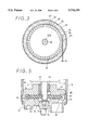
- FIG. 3 is a horizontal cross-sectional view of the westco pump
- FIG. 4A is a perspective view of the casing body and FIG. 4B is a perspective view of the casing cover;
- FIG. 5 is a longitudinal cross-sectional front view of the entire structure of the westco pump
- FIG. 6 is a longitudinal cross-sectional front view of the entire structure of a fuel pump
- FIG. 7 is a graph of experimental results showing the relationship between the shift amount and noise
- FIG. 8 is a cross-sectional view showing a second embodiment of the invention.
- FIG. 9 is a horizontal cross-sectional view of the casing body
- FIG. 10 is a cross-sectional view showing a third embodiment of the invention.
- FIG. 11 is a perspective view showing a fourth embodiment of the invention.
- FIG. 12 is a partial perspective view of a modification of the impeller.
- FIGS. 13A and 13B are a longitudinal partial cross-sectional view and a partial perspective view of a prior art westco pump.
- a fuel pump is composed of a pump section 11 and a motor section 12 to drive the pump section 11.
- the motor 12 is composed of a DC motor with a brush.
- Permanent magnets 14 are located in a cylindrical form in a cylindrical housing 13.
- a rotor 15 is located concentrically in the inner circumference of the permanent magnets 14.
- the pump section 11 is composed of a westco pump. As shown in FIG. 5, it is composed of a casing body 18 including as a single unit a circular peripheral wall 16 containing a circular inner circumference and a side wall 17 closing one side of the circular peripheral wall 16, a casing cover 19 acting as a side wall to close the other side of the circular peripheral wall 16, and an impeller 20.
- the casing body 18 and the casing cover 19 are formed, for example, by aluminum diecast molding.
- the casing body 18 is press-fitted on one end of the housing 13 while the casing cover 19 is secured to one end of the housing 13 by crimping, etc. in such a way that it covers the casing body 18.
- This provides a hermetically sealed single casing 21 composed of the casing body 18 and the casing cover 19.
- a shaft 22 of the rotor 15 acting as the drive axle of the pump section 11 is inserted and supported in such a way that it can rotate freely in a bearing 23 fitted in the center of the side wall 17 of the casing body 18, so that the thrust load is received by a thrust bearing 24 secured to the center of the casing cover 19.
- the impeller 20 is formed integrally by phenol resin with glass fiber or PPS and formed with multiple blade elements 25 on the outer circumference thereof in a circumferential direction at a fixed interval.
- a separating wall 27 dividing blade grooves 26 (FIG. 1 and FIG. 3) of the blade elements 25 in an axial direction is also formed.
- the blade elements 25 protruding into both sides of the separating wall 27 are so configured that they are located at the same position.
- the impeller 20 is housed in the casing 21 rotatably.
- a joining hole 28 (FIG. 3) located in the center and having roughly a D-shape is fitted slidably in an axial direction on a D-cut section 22a of the shaft 22 acting as a rotation axle. As a result, the impeller 20 rotates together with the shaft 22 as a single unit and is movable in the axial direction in relation to the shaft 22.
- the casing cover 19 is formed with an intake hole 29 communicating with a fuel tank (not shown in figures).
- a discharge hole 30 (FIG. 1) communicating with an injector (not shown in figures).
- Formed on the inner circumference of the casing 21 is a pump channel 31 connecting the intake hole 29 and the discharge hole 30.
- the blade elements 25 of the impeller 20 are protruding into the pump channel 31.
- one end of the two terminal ends of the pump channel 31 on the side of the intake hole 29 is denoted as the "starting end” and the other end of the same on the side of the discharge hole 30 is denoted as the "finishing end.”
- one part of the pump channel 31 at the side of the outer circumference of the blade elements 25 is formed by designing the inside diameter of the circular peripheral wall 16 of the casing body 18 larger than the outside diameter of the impeller 20.
- the other part of the pump channel 31 at the axial sides of the blade elements 25 are formed, as shown in FIGS. 4A and 4B, by grooves 32 and 33 on the inner surface of the side wall 17 of the casing body 18 and the inner surface of the casing cover 19.
- the part located between the end of the groove 32 in the position opposing the intake hole 29 of the casing cover 19 and the discharge hole 30 projects out in an arc-shape.
- the arc-shaped projection works as the radial seal 34.
- the parts between both ends of the groove 32 of the side wall 17 of the casing body 18 and between both ends of the groove 33 of the casing cover 19 (i.e., the parts projecting from the bottom side of the groove 33 and being flush with the inner surfaces of the side wall 17 and the casing cover 19) work as the axial seals 35 and 36.
- the lengths in a circumferential direction of the axial seals 35 and 36 of the side wall 17 and the casing cover 19 are set to the same value.
- the radial clearance Rc is set, for example, between 50 micrometers and 150 micrometers, and the axial clearance Ac (sum of Ac1 and Ac2) is set, for example, between several micrometers and several tens of micrometers.
- the radial clearance Rc is set larger than the axial clearance Ac.
- the inventors have found that, when the radial clearance Rc is greater than the axial clearance Ac as described above, the main source of noise is the sound generated when the fluid sent from the impeller blade groove collides simultaneously with the finishing ends of both sides in an axial direction of the blade elements in the finishing end of the pump channel.
- the finishing end of the groove 32 (pump channel) of the side wall 17 of the casing body 18 and the finishing end of the groove 33 (the pump channel) of the casing cover 19 are designed so that they are shifted in a circumferential direction.
- a finishing end 32a of the groove 32 of the side wall 17 including the discharge hole 30 is shifted, relative to a finishing end 33a of the groove 33 of the casing cover 19 acting as the other side wall, by an amount equal to about one half of the pitch P of the circumferentially adjacent two of the blade elements 25 in the rotational direction (shown by an arrow B in the figure) of the impeller 20.
- the lengths in a circumferential direction of the axial seal 35 of the side wall 17 of the casing body 18 and the axial seal 36 of the casing cover 19 are set to the same length.
- a starting end 32b of the groove 32 of the side wall 18 is shifted, also by an amount equal to about one half of the pitch distance of the blade element 25 of the impeller 20 in a rotational direction, relative to a starting end 33b of the groove 33 of the casing cover 19.
- the fuel collides with the finishing end of the pump channel 31, end surface 34a of the radial seal 34 and the finishing ends 32a, 33a of the grooves 32 and 33, and is discharged from the discharge hole 30 while changing flow direction. It is then sent under pressure to the injector (not shown in the figures).
- the main source of noise is the sound generated when the fuel under high pressure collides with the finishing ends 32a, 33a of the grooves 32, 33 of the pump channel 31.
- the finishing ends 32a and 33a of the grooves 32, 33 are shifted from each other in a circumferential direction so that the timings by which the fuel under high pressure hits the finishing ends 32a and 33a are staggered, thus effectively reducing noise during operation of the pump.
- the finishing end 32a of the groove 32 of the side wall 17 is shifted in the rotational direction of the impeller 20 relative to the finishing end 33a of the groove 33 of the casing cover 19.
- the shift amount is set as roughly one half of the pitch P of the blade elements 25, thus achieving an even greater reduction in noise.
- FIG. 7 shows the results of changing the shift amount of the finishing ends 32a, 33a of the grooves 32, 33 and the measured result of the amount of noise.
- the shift amount is expressed as a minus value when the finishing end 32a of the groove 32 of the side wall 17 containing the discharge hole 30 is shifted in the rotational direction of the impeller 20 in relation to the finishing end 33a of the groove 33 of the casing cover 19.
- the noise reduction effect is greater in the present embodiment where the finishing end 32a of the groove 32 is shifted by an amount equal to about 1/2 the pitch P of the blade elements 25 in the rotational direction of the impeller 20 relative to the finishing end 33a of the groove 33.
- the shift amount is (+P/2) (i.e., if the finishing end 32a of the groove 32 is shifted by an amount P/2 in the opposite direction of the rotational direction of the impeller 20 relative to the finishing end 33a of the groove 33), there is almost no noticeable reduction in noise. As is explained later, this is because the finishing end 33a of the groove 33 is on the rotational direction side of the impeller 20 relative to the discharge hole 30 and, hence the fuel hitting the finishing end 33a of the groove 33 has no place to escape and the pressure increases.
- the finishing end 32a, 33a of the grooves 32, 33 the finishing end 32a of the groove 32 of the side wall 17 including the discharge hole 30 is shifted in the rotational direction of the impeller 20 relative to the finishing end 33a of the groove 33 of the casing cover 19. As a result, the fuel hitting the finishing end 33a of the groove 33 smoothly changes flow direction and flows out from the discharge hole 30.
- the finishing end 32a of the groove 32 of the side wall 17 including the discharge hole 30 is shifted in the rotational direction of the impeller 20 relative to the finishing end 33a of the groove 33 of the casing cover 19.
- the fuel hitting the finishing end 33a of the groove 33 changes its flow direction smoothly and flows out from the discharge hole 30.
- fuel hitting the finishing ends of the grooves 32, 33 may flow to the starting ends 32b, 33b of the grooves 32, 33 via the axial clearances Ac1, Ac2.
- the starting ends 32b, 33b are shifted by an amount equal to 1/2 of the pitch P of the blade elements 25 in the rotational direction of the impeller 20.
- the starting ends 32b, 33b are shifted by an amount equal to 1/2 of the pitch P of the blade elements 25 in the rotational direction of the impeller 20.
- FIG. 8 and FIG. 9 show a second embodiment of the invention.
- the same reference numerals are used for parts that are the same as in the first embodiment in FIG. 1, and there is description of differing parts.
- the finishing end of the groove 32 itself of the side wall 17 of the casing body 18 and the finishing end 33a of the groove 33 of the casing cover 19 are located in the same position in the circumferential direction.
- Formed is an extension groove 37 whose length from the finishing end of the groove 32 itself of the side wall 17 of the casing body 18 in the rotational direction of the impeller 20 is equal to 1/2 of the pitch P of the blade element 25.
- the finishing end 32a of the groove 32 including the extension groove 37 is formed so that it is substantially shifted by an amount equal to roughly 1/2 of the pitch P of the blade elements 25 in the rotational direction of the impeller 20 relative to the finishing end 33a of the groove 33.
- the inner surface of the extension groove 37 is formed along a slanted surface 37a, and the shock when the fuel hits the finishing end 32a of the extension groove 32 is relieved by the slanted surface 37a so that the noise reduction effect is increased.
- Such an extension groove 37 can be formed in both grooves 32 and 33. Such a case is shown as a third embodiment in FIG. 10.
- the finishing end of the groove 32 of the side wall 17 of the casing body 18 and the finishing end of the groove 33 of the casing cover 19 are located in the same position in relation to a circumferential direction.
- Extension grooves 38, 39 with different lengths are formed in the finishing ends of the grooves 32, 33 extending in the rotational direction of the impeller 20.
- the finishing ends 32a, 33a of the grooves 32, 33 are in a condition where they are substantially shifted in the circumferential direction.
- the extension groove 38 is formed so that it is shifted an amount equal to 1/2 the pitch P of the blade elements 25 in the rotational direction of the impeller 20 in relation to extension groove 39.
- the radial clearance Rc is made larger than the axial clearance Ac.
- a fourth embodiment in FIG. 11 shows a structure for noise reduction in the case where the axial clearance Ac is made larger than the radial clearance Rc. If Rc ⁇ Ac, the main cause of noise generation is fuel under high pressure hitting the finishing end (one end of radial seal 34) of the pump channel 31 of the circular peripheral wall 16 of the casing body 18.
- the fourth embodiment in FIG. 11 at one end of the radial seal 34 which is the finishing end of the pump channel 31 of the circular peripheral wall 16, the position of the end surfaces 34b, 34c on both sides of the separating wall 27 of the impeller 20 in an axial direction are shifted in the rotational direction of the impeller 20.
- the end surfaces 34b, 34d of the side wall 17 including the discharge hole 30 are shifted in the rotational direction of the impeller 20 by an amount equal to 1/2 of the pitch P of the blade elements 25 of the impeller 20 relative to the end surfaces 34c, 34e on the opposite side.
- the end surface 34b on the side of the discharge hole 30 passes on a straight line through the outside of the casing body 18 to form one part of the inner surface of the discharge hole 30.
- the fuel which hits the end surface 34b changes flow direction and is discharged smoothly from the discharge hole 30.
- the fuel which flows in the pump channel 31 towards the discharge hole 30 hits the end surfaces 34b, 34c which are the finishing ends. At this time, because the positions of the end surfaces 34b and 34c are dislocated, there occurs staggering of timings and effective noise reduction is attained.
- the positions of the end surfaces 34d, 34e that are the starting ends of the pump channel 31 are also shifted. Therefore, even if the fuel under high pressure leaks to the starting ends via the radial clearance Rc, because the timings of reduction in pressure on both sides of the separating wall 27 of the impeller 20 due to fuel leak to the starting ends of the pump channel 31 are staggered, there is effective noise reduction on the starting end of the pump channel 31.
- use of the westco pump in this invention is not limited to use as a fuel pump. It can be used widely as a pump for fluids. Further, the invention may be applied to a westco pump which has, as shown in FIG. 12, an impeller 20 formed with blade elements 25 and a separation wall 27.
- the blade elements 25 are made into an arcuate shape and the separation wall 27 is made shorter radially than the top ends of the blade elements 25.
- the finishing ends of the pump channel formed in both side walls of the casing are shifted in the circumferential direction.
- the timings of collision of fluid at the pump channel finishing end at both side walls (the main cause of noise) is staggered at both side walls, thus reducing noise.
- the finishing end of the pump channel formed on the inner surface of one of the side walls shifts in the rotational direction of the impeller relative to the finishing end of the pump channel formed on the inner surface of the other side wall.
- the fluid which reaches the finishing end of the pump channel is smoothly discharged from the discharge hole and there occurs no abnormal wear caused by the impeller being pushed in the direction of thrust.
- the finishing end of the pump channel formed in the inner circumference of the circular peripheral wall of the casing is shifted in the circumferential direction on both sides of the separating wall of the impeller.
- the timings of the collision of the fluid against the pump channel finishing end of the circular peripheral wall is staggered at both side walls, thus reducing noise.
Landscapes
- Engineering & Computer Science (AREA)
- Mechanical Engineering (AREA)
- General Engineering & Computer Science (AREA)
- Structures Of Non-Positive Displacement Pumps (AREA)
Priority Applications (1)
| Application Number | Priority Date | Filing Date | Title |
|---|---|---|---|
| US08/597,569 US5716191A (en) | 1994-06-30 | 1996-02-02 | Westco pump and noise suppression structure |
Applications Claiming Priority (4)
| Application Number | Priority Date | Filing Date | Title |
|---|---|---|---|
| JP14905294A JP3463356B2 (ja) | 1994-06-30 | 1994-06-30 | ウエスコポンプ |
| JP6-149052 | 1994-06-30 | ||
| US48305295A | 1995-06-07 | 1995-06-07 | |
| US08/597,569 US5716191A (en) | 1994-06-30 | 1996-02-02 | Westco pump and noise suppression structure |
Related Parent Applications (1)
| Application Number | Title | Priority Date | Filing Date |
|---|---|---|---|
| US48305295A Continuation | 1994-06-30 | 1995-06-07 |
Publications (1)
| Publication Number | Publication Date |
|---|---|
| US5716191A true US5716191A (en) | 1998-02-10 |
Family
ID=15466610
Family Applications (1)
| Application Number | Title | Priority Date | Filing Date |
|---|---|---|---|
| US08/597,569 Expired - Lifetime US5716191A (en) | 1994-06-30 | 1996-02-02 | Westco pump and noise suppression structure |
Country Status (6)
| Country | Link |
|---|---|
| US (1) | US5716191A (de) |
| EP (2) | EP0690233B1 (de) |
| JP (1) | JP3463356B2 (de) |
| KR (1) | KR100269651B1 (de) |
| DE (2) | DE69523642T2 (de) |
| HU (1) | HU218455B (de) |
Cited By (13)
| Publication number | Priority date | Publication date | Assignee | Title |
|---|---|---|---|---|
| US6017183A (en) * | 1996-08-29 | 2000-01-25 | Robert Bosch Gmbh | Flow pump |
| US6113363A (en) * | 1999-02-17 | 2000-09-05 | Walbro Corporation | Turbine fuel pump |
| US6126386A (en) * | 1996-09-06 | 2000-10-03 | Honda Giken Kogyo Kabushiki Kaisha | Pump and medium circulation apparatus |
| US6231300B1 (en) | 1996-04-18 | 2001-05-15 | Mannesmann Vdo Ag | Peripheral pump |
| WO2001071193A1 (de) * | 2000-03-21 | 2001-09-27 | Siemens Aktiengesellschaft | Förderpumpe |
| US6425733B1 (en) | 2000-09-11 | 2002-07-30 | Walbro Corporation | Turbine fuel pump |
| US6659713B1 (en) | 1999-02-09 | 2003-12-09 | Aisin Kogyo Kabushiki Kaisha | Fluid pumps |
| US20040228721A1 (en) * | 2003-05-15 | 2004-11-18 | Masatoshi Takagi | Fuel pump |
| US6824361B2 (en) | 2002-07-24 | 2004-11-30 | Visteon Global Technologies, Inc. | Automotive fuel pump impeller with staggered vanes |
| US6890144B2 (en) | 2002-09-27 | 2005-05-10 | Visteon Global Technologies, Inc. | Low noise fuel pump design |
| US20070031239A1 (en) * | 2005-04-08 | 2007-02-08 | Asian Kogyo Kabushiki Kaisha | Fuel pump |
| CN104040180A (zh) * | 2011-10-13 | 2014-09-10 | 三菱电机株式会社 | 燃料泵 |
| US9249806B2 (en) | 2011-02-04 | 2016-02-02 | Ti Group Automotive Systems, L.L.C. | Impeller and fluid pump |
Families Citing this family (14)
| Publication number | Priority date | Publication date | Assignee | Title |
|---|---|---|---|---|
| DE4427874C2 (de) * | 1994-08-06 | 2003-06-18 | Bosch Gmbh Robert | Aggregat zum Fördern von Kraftstoff aus einem Vorratstank zur Brennkraftmaschine eines Kraftfahrzeuges |
| US6126387A (en) * | 1996-08-26 | 2000-10-03 | Aisan Kogyo Kabushiki Kaisha | Fuel pump having low operating noise |
| DE19638843C1 (de) * | 1996-09-21 | 1998-01-08 | Ford Werke Ag | Schwungscheibe für Verbrennungskraftmaschine |
| JP3653972B2 (ja) * | 1998-02-19 | 2005-06-02 | 三菱電機株式会社 | 電動燃料ポンプ |
| ES1042460Y (es) * | 1999-02-24 | 2000-05-16 | Heating Elements I Z S L | Radiador electrico perfeccionado. |
| DE10149408C1 (de) * | 2001-10-06 | 2003-01-09 | Xaver Gruenwald Gmbh | Vorrichtung zur Befestigung von Leistenschienen, insbesondere von als Sockelleisten ausgebildeten Leistenschienen |
| JP2003336591A (ja) * | 2002-03-13 | 2003-11-28 | Aisan Ind Co Ltd | ウエスコ式ポンプ |
| JP2004068645A (ja) | 2002-08-02 | 2004-03-04 | Aisan Ind Co Ltd | ウエスコ式ポンプ |
| JP2005016312A (ja) | 2003-06-23 | 2005-01-20 | Aisan Ind Co Ltd | 燃料ポンプ |
| DE112005002121B4 (de) * | 2004-09-08 | 2017-11-02 | Mitsuba Corp. | Kraftstoffpumpe |
| DE102004058533B4 (de) * | 2004-12-04 | 2011-04-21 | Brinkmann Pumpen K.H. Brinkmann Gmbh & Co. Kg | Pumpe für Flüssigkeiten unter Überdruck |
| DE102007025510A1 (de) * | 2007-06-01 | 2008-12-04 | Continental Automotive Gmbh | Kraftstoffpumpe |
| GB2477178B (en) * | 2010-02-18 | 2012-01-11 | Quail Res And Design Ltd | Improved Pump |
| DE102010046870B4 (de) * | 2010-09-29 | 2016-09-22 | Pierburg Gmbh | Seitenkanalgebläse, insbesondere Sekundärluftgebläse für eine Verbrennungskraftmaschine |
Citations (17)
| Publication number | Priority date | Publication date | Assignee | Title |
|---|---|---|---|---|
| US2220538A (en) * | 1937-07-30 | 1940-11-05 | Micro Westco Inc | Pump |
| JPS56120389A (en) * | 1980-02-27 | 1981-09-21 | Seiki Kogyo Kk | Ink supply device for single-barrel rotary copying machine |
| US4478550A (en) * | 1981-04-22 | 1984-10-23 | Nippondenso Co., Ltd. | Pump apparatus |
| JPS60173390A (ja) * | 1984-02-16 | 1985-09-06 | Nippon Denso Co Ltd | 電動式燃料ポンプ |
| JPS63105296A (ja) * | 1986-10-20 | 1988-05-10 | Japan Electronic Control Syst Co Ltd | タ−ビン型燃料ポンプ |
| US4844621A (en) * | 1985-08-10 | 1989-07-04 | Nippondenso Co., Ltd. | Fuel pump with passage for attenuating noise generated by impeller |
| GB2220706A (en) * | 1988-07-08 | 1990-01-17 | Caradon Mira Ltd | Pump |
| US5011367A (en) * | 1989-01-31 | 1991-04-30 | Aisan Kogyo Kabushiki Kaisha | Fuel pump |
| US5163810A (en) * | 1990-03-28 | 1992-11-17 | Coltec Industries Inc | Toric pump |
| JPH04350394A (ja) * | 1990-08-10 | 1992-12-04 | Nippondenso Co Ltd | 燃料ポンプ |
| GB2263311A (en) * | 1992-01-14 | 1993-07-21 | Mitsubishi Electric Corp | Electric fuel pump. |
| US5273394A (en) * | 1992-09-24 | 1993-12-28 | General Motors Corporation | Turbine pump |
| US5281083A (en) * | 1991-06-18 | 1994-01-25 | Hitachi, Ltd. | Vortex flow blower |
| JPH06137300A (ja) * | 1992-10-21 | 1994-05-17 | Hitachi Ltd | ボルテックスポンプ |
| US5336045A (en) * | 1992-01-22 | 1994-08-09 | Nippondenso Co., Ltd. | Fuel pump |
| US5372475A (en) * | 1990-08-10 | 1994-12-13 | Nippondenso Co., Ltd. | Fuel pump |
| US5407318A (en) * | 1992-12-08 | 1995-04-18 | Nippondenso Co., Ltd. | Regenerative pump and method of manufacturing impeller |
Family Cites Families (3)
| Publication number | Priority date | Publication date | Assignee | Title |
|---|---|---|---|---|
| JP2661019B2 (ja) * | 1986-09-19 | 1997-10-08 | 松下電器産業株式会社 | ウエスコポンプ |
| JPH06149052A (ja) | 1992-11-12 | 1994-05-27 | Ricoh Co Ltd | トナーカートリッジ |
| JP3052623B2 (ja) * | 1992-11-26 | 2000-06-19 | 株式会社デンソー | 再生ポンプ |
-
1994
- 1994-06-30 JP JP14905294A patent/JP3463356B2/ja not_active Expired - Lifetime
-
1995
- 1995-06-16 HU HU9501782A patent/HU218455B/hu unknown
- 1995-06-27 DE DE69523642T patent/DE69523642T2/de not_active Expired - Lifetime
- 1995-06-27 EP EP95110016A patent/EP0690233B1/de not_active Expired - Lifetime
- 1995-06-27 DE DE69515564T patent/DE69515564T2/de not_active Expired - Lifetime
- 1995-06-27 EP EP98122741A patent/EP0909897B1/de not_active Expired - Lifetime
- 1995-06-29 KR KR1019950018101A patent/KR100269651B1/ko not_active IP Right Cessation
-
1996
- 1996-02-02 US US08/597,569 patent/US5716191A/en not_active Expired - Lifetime
Patent Citations (17)
| Publication number | Priority date | Publication date | Assignee | Title |
|---|---|---|---|---|
| US2220538A (en) * | 1937-07-30 | 1940-11-05 | Micro Westco Inc | Pump |
| JPS56120389A (en) * | 1980-02-27 | 1981-09-21 | Seiki Kogyo Kk | Ink supply device for single-barrel rotary copying machine |
| US4478550A (en) * | 1981-04-22 | 1984-10-23 | Nippondenso Co., Ltd. | Pump apparatus |
| JPS60173390A (ja) * | 1984-02-16 | 1985-09-06 | Nippon Denso Co Ltd | 電動式燃料ポンプ |
| US4844621A (en) * | 1985-08-10 | 1989-07-04 | Nippondenso Co., Ltd. | Fuel pump with passage for attenuating noise generated by impeller |
| JPS63105296A (ja) * | 1986-10-20 | 1988-05-10 | Japan Electronic Control Syst Co Ltd | タ−ビン型燃料ポンプ |
| GB2220706A (en) * | 1988-07-08 | 1990-01-17 | Caradon Mira Ltd | Pump |
| US5011367A (en) * | 1989-01-31 | 1991-04-30 | Aisan Kogyo Kabushiki Kaisha | Fuel pump |
| US5163810A (en) * | 1990-03-28 | 1992-11-17 | Coltec Industries Inc | Toric pump |
| JPH04350394A (ja) * | 1990-08-10 | 1992-12-04 | Nippondenso Co Ltd | 燃料ポンプ |
| US5372475A (en) * | 1990-08-10 | 1994-12-13 | Nippondenso Co., Ltd. | Fuel pump |
| US5281083A (en) * | 1991-06-18 | 1994-01-25 | Hitachi, Ltd. | Vortex flow blower |
| GB2263311A (en) * | 1992-01-14 | 1993-07-21 | Mitsubishi Electric Corp | Electric fuel pump. |
| US5336045A (en) * | 1992-01-22 | 1994-08-09 | Nippondenso Co., Ltd. | Fuel pump |
| US5273394A (en) * | 1992-09-24 | 1993-12-28 | General Motors Corporation | Turbine pump |
| JPH06137300A (ja) * | 1992-10-21 | 1994-05-17 | Hitachi Ltd | ボルテックスポンプ |
| US5407318A (en) * | 1992-12-08 | 1995-04-18 | Nippondenso Co., Ltd. | Regenerative pump and method of manufacturing impeller |
Non-Patent Citations (6)
| Title |
|---|
| E. Tonn, "Zur Berechnung von Peripheralpumpen" Konstruktion 44 (1992) 64-70. |
| E. Tonn, Zur Berechnung von Peripheralpumpen Konstruktion 44 (1992) 64 70. * |
| Patent Abstract of Japan, vol. 012 No. 305 (M 733) Aug. 1988 re JP A 63 080092. * |
| Patent Abstract of Japan, vol. 012 No. 305 (M-733) Aug. 1988 re-JP-A 63 080092. |
| Patent Abstract of Japan, vol. 018 No. 491 (M 1672) Sep. 1994 re JP A 06 159283. * |
| Patent Abstract of Japan, vol. 018 No. 491 (M-1672) Sep. 1994 re JP-A 06 159283. |
Cited By (14)
| Publication number | Priority date | Publication date | Assignee | Title |
|---|---|---|---|---|
| US6231300B1 (en) | 1996-04-18 | 2001-05-15 | Mannesmann Vdo Ag | Peripheral pump |
| US6017183A (en) * | 1996-08-29 | 2000-01-25 | Robert Bosch Gmbh | Flow pump |
| US6126386A (en) * | 1996-09-06 | 2000-10-03 | Honda Giken Kogyo Kabushiki Kaisha | Pump and medium circulation apparatus |
| US6659713B1 (en) | 1999-02-09 | 2003-12-09 | Aisin Kogyo Kabushiki Kaisha | Fluid pumps |
| US6113363A (en) * | 1999-02-17 | 2000-09-05 | Walbro Corporation | Turbine fuel pump |
| WO2001071193A1 (de) * | 2000-03-21 | 2001-09-27 | Siemens Aktiengesellschaft | Förderpumpe |
| US6425733B1 (en) | 2000-09-11 | 2002-07-30 | Walbro Corporation | Turbine fuel pump |
| US6824361B2 (en) | 2002-07-24 | 2004-11-30 | Visteon Global Technologies, Inc. | Automotive fuel pump impeller with staggered vanes |
| US6890144B2 (en) | 2002-09-27 | 2005-05-10 | Visteon Global Technologies, Inc. | Low noise fuel pump design |
| US20040228721A1 (en) * | 2003-05-15 | 2004-11-18 | Masatoshi Takagi | Fuel pump |
| US20070031239A1 (en) * | 2005-04-08 | 2007-02-08 | Asian Kogyo Kabushiki Kaisha | Fuel pump |
| US7766604B2 (en) | 2005-04-08 | 2010-08-03 | Aisan Kogyo Kabushiki Kaisha | Fuel pump |
| US9249806B2 (en) | 2011-02-04 | 2016-02-02 | Ti Group Automotive Systems, L.L.C. | Impeller and fluid pump |
| CN104040180A (zh) * | 2011-10-13 | 2014-09-10 | 三菱电机株式会社 | 燃料泵 |
Also Published As
| Publication number | Publication date |
|---|---|
| DE69515564T2 (de) | 2000-08-31 |
| EP0909897A1 (de) | 1999-04-21 |
| KR100269651B1 (ko) | 2000-11-01 |
| HUT75000A (en) | 1997-03-28 |
| JPH0814184A (ja) | 1996-01-16 |
| HU9501782D0 (en) | 1995-08-28 |
| DE69523642T2 (de) | 2002-08-08 |
| DE69515564D1 (de) | 2000-04-20 |
| DE69523642D1 (de) | 2001-12-06 |
| HU218455B (hu) | 2000-08-28 |
| EP0690233B1 (de) | 2000-03-15 |
| JP3463356B2 (ja) | 2003-11-05 |
| KR960001497A (ko) | 1996-01-25 |
| EP0690233A1 (de) | 1996-01-03 |
| EP0909897B1 (de) | 2001-10-31 |
Similar Documents
| Publication | Publication Date | Title |
|---|---|---|
| US5716191A (en) | Westco pump and noise suppression structure | |
| KR102631733B1 (ko) | 전기 모터 구동식 액체 펌프 | |
| CN110914549B (zh) | 螺杆主轴泵、燃料泵组件和燃料泵单元 | |
| US20110135516A1 (en) | Electric pump | |
| JPH05508459A (ja) | 自動車のリザーブタンクから内燃機関に燃料を供給するための燃料フィードユニット | |
| US9890782B2 (en) | Fluid pump with radial bearing between inner rotor and rotary shaft and lubrication groove in outer peripheral surface of radial bearing | |
| US5660536A (en) | High capacity simplified sea water pump | |
| US6547515B2 (en) | Fuel pump with vapor vent | |
| JPS59141762A (ja) | 燃料ポンプ | |
| KR20050098172A (ko) | 로터리 압축기의 가스누설 저감구조 | |
| KR101925618B1 (ko) | 연료펌프 | |
| US20080031733A1 (en) | Fuel Pump | |
| US20160333875A1 (en) | Fuel pump | |
| EP1295038B1 (de) | Kraftstoffpumpe mit verringerter empfindlichkeit für verschmutzung | |
| CN114072602B (zh) | 密封环 | |
| JP2001280261A (ja) | 燃料ポンプ | |
| KR100590650B1 (ko) | 차량용 진공펌프 | |
| CN113557379A (zh) | 密封环及密封结构 | |
| JP2891047B2 (ja) | ベーン式真空ポンプ | |
| US6729841B2 (en) | Turbine pump | |
| CN213684501U (zh) | 油泵 | |
| JP2000027768A5 (de) | ||
| KR100348481B1 (ko) | 차량용 진공펌프 | |
| JP3582555B2 (ja) | 再生ポンプ | |
| CN111237467A (zh) | 特别是用于发动机轴的密封装置 |
Legal Events
| Date | Code | Title | Description |
|---|---|---|---|
| STCF | Information on status: patent grant |
Free format text: PATENTED CASE |
|
| FPAY | Fee payment |
Year of fee payment: 4 |
|
| FPAY | Fee payment |
Year of fee payment: 8 |
|
| FPAY | Fee payment |
Year of fee payment: 12 |