US5538128A - Grate for a furnace - Google Patents
Grate for a furnace Download PDFInfo
- Publication number
- US5538128A US5538128A US08/324,658 US32465894A US5538128A US 5538128 A US5538128 A US 5538128A US 32465894 A US32465894 A US 32465894A US 5538128 A US5538128 A US 5538128A
- Authority
- US
- United States
- Prior art keywords
- grate
- bar
- fastened
- fastening
- locking means
- Prior art date
- Legal status (The legal status is an assumption and is not a legal conclusion. Google has not performed a legal analysis and makes no representation as to the accuracy of the status listed.)
- Expired - Fee Related
Links
- 230000002265 prevention Effects 0.000 claims abstract description 25
- 230000008878 coupling Effects 0.000 claims abstract description 8
- 238000010168 coupling process Methods 0.000 claims abstract description 8
- 238000005859 coupling reaction Methods 0.000 claims abstract description 8
- 230000004888 barrier function Effects 0.000 claims 1
- 238000006073 displacement reaction Methods 0.000 description 5
- 238000012423 maintenance Methods 0.000 description 5
- 239000000463 material Substances 0.000 description 5
- 230000008901 benefit Effects 0.000 description 3
- 238000002485 combustion reaction Methods 0.000 description 3
- 238000010276 construction Methods 0.000 description 3
- 239000000969 carrier Substances 0.000 description 2
- 238000003780 insertion Methods 0.000 description 2
- 230000037431 insertion Effects 0.000 description 2
- 238000000034 method Methods 0.000 description 2
- 230000009471 action Effects 0.000 description 1
- 230000001186 cumulative effect Effects 0.000 description 1
- 238000007689 inspection Methods 0.000 description 1
- 230000008569 process Effects 0.000 description 1
- 230000009467 reduction Effects 0.000 description 1
- 230000000630 rising effect Effects 0.000 description 1
- 238000000926 separation method Methods 0.000 description 1
Images


Classifications
-
- F—MECHANICAL ENGINEERING; LIGHTING; HEATING; WEAPONS; BLASTING
- F23—COMBUSTION APPARATUS; COMBUSTION PROCESSES
- F23H—GRATES; CLEANING OR RAKING GRATES
- F23H17/00—Details of grates
-
- F—MECHANICAL ENGINEERING; LIGHTING; HEATING; WEAPONS; BLASTING
- F23—COMBUSTION APPARATUS; COMBUSTION PROCESSES
- F23H—GRATES; CLEANING OR RAKING GRATES
- F23H7/00—Inclined or stepped grates
- F23H7/06—Inclined or stepped grates with movable bars disposed parallel to direction of fuel feeding
- F23H7/08—Inclined or stepped grates with movable bars disposed parallel to direction of fuel feeding reciprocating along their axes
Definitions
- the invention relates to a grate for a furnace according to the pre-characterizing clause of Claim 1.
- Grates of this kind are used for the incineration and simultaneous further conveying of material to be burned, and are mainly employed in refuse incineration plants.
- a grate of this kind which has at the edge a holding device which is fastened to a side cheek and by which the lateral movability of an edge bar towards the centre of the grate is limited.
- it allows the edge bar vertical clearance, which in one embodiment is even unlimited in the upward direction.
- the invention is to provide a remedy.
- the invention as characterized in the claims, supplies a grate in which the rows of grate bars are reliably fastened in respect of their angular position and thus the upward swivelling of an entire row of grate bars is reliably eliminated, while the upward swivelling of rows of grate bars and the removal of grate bars for maintenance purposes is immediately possible, without maintenance personnel having to enter the under-grate blast region to do this.
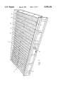
- FIG. 1 is a view in perspective of a grate according to the invention
- FIG. 2 shows a part of a longitudinal section, extending in each case between two grate bars, through the middle region of the grate shown in FIG. 1,
- FIG. 3 shows a part of a corresponding longitudinal section extending in each case between an edge bar and the next grate bar
- FIG. 4 shows an interrupted cross-section through a row of fixed bars and the connection means between the grate bars and swivelling prevention fastenings or swivelling prevention and longitudinal fastenings of the edge bars
- FIG. 5 shows a cross-section in the edge region through a swivelling prevention and longitudinal fastening of an edge bar according to another embodiment
- FIG. 6 shows a longitudinal section through the fastened edge bar shown in FIG. 5,
- FIG. 7 shows another longitudinal section through the fastened edge bar shown in FIG. 5,
- FIG. 8 shows a cross-section in the edge region through a swivelling prevention and longitudinal fastening of a fastened edge bar according to another embodiment
- FIG. 9 shows a longitudinal section through the fastened edge bar shown in FIG. 8,
- FIG. 10 shows a cross-section in the edge region through a longitudinal fastening of a fastened edge bar
- FIG. 10a shows a part of the cross-section according to FIG. 10, with the longitudinal fastening partly released
- FIG. 11 shows a cross-section in the edge region through a longitudinal fastening of an edge bar according to another embodiment
- FIG. 12 shows a part of a longitudinal section similar to FIG. 3, but in the case of a modified embodiment having a middle beam, the longitudinal section extending in each case between an edge bar on the middle beam and the next following grate bar, and also through a longitudinal fastening according to another embodiment, and
- FIG. 13 shows a cross-section through the middle beam shown in FIG. 12, with the grate bars adjoining on both sides and the longitudinal fastening.
- FIG. 1 shows in an oblique top view a grate according to the invention, comprising a grate track 1, which is bounded on both sides by side walls having side cheeks 2 pressed into contact with limited lateral movability. It may also comprise two or more grate tracks arranged side by side and separated by middle beams.
- the grate track 1 consists of rows 3 of fixed bars and rows 3' of movable bars, which alternate in the longitudinal direction and which in each case are formed by grate bars 4 arranged side by side. The rear ends of the grate bars 4 rest in each case (FIG.
- a grate bar carrier 5 which here is in the form of a rod of circular cross-section, which they embrace by a front stop lug 6a and a rear stop lug 6b, said lugs projecting downwards and limiting the longitudinal movability of the grate bar 4 relative to the grate bar carrier 5, the latter being embraced alternately in the transverse direction by the stop lugs 6a, b of the grate bars 4 semicircularly with a close fit or (not illustrated) in a half oval shape with spacing, that is to say giving the grate bar 4 some clearance in the longitudinal direction, so that grate bars lying side by side are slightly movable in the longitudinal direction relative to one another.
- the grate bars 4 simply rest on the grate bar carriers 5, so that on being lifted they are detachable and movable laterally.
- a forwardly rising surface 7 of the grate bar 4 is in each case bent over downwardly and forms a front surface 8, which is directed approximately at right angles to the surface 7.
- the grate bars 4 of a row 3, 3' of grate bars lie in each case with the front end on the surface of a grate bar 4 of the next row 3'; 3 of grate bars, that is to say the grate bars of a fixed bar row 3 lie on those of a movable bar row 3', and vice versa.
- the movable bar rows 3' are caused by the grate bar carriers 5 on which their grate bars rest, and which are swivellably suspended and are driven, for example, by pistons 9 (FIG. 1, only one being shown), to make a reciprocating cyclical movement in the longitudinal direction, the movements of successive movable bar rows 3' being in each case displaced in phase by 180°.
- the grate bars 4 are in each case connected on both sides to their nearest neighbours by couplings.
- Each grate bar 4 has two side ribs 10 projecting downwards at the side edges.
- a bore 11 (FIG. 4) into which a bolt 12, which is directed transversely to the longitudinal direction, is inserted and held fast by a nut 13.
- the grate bars 4 lying in between have at the same height longitudinal slots 14 which are open at the rear and through which projects in each case the bolt 12 inserted through the bore 11 in the neighbouring bar and carrying a head 15 at its end.
- the bolt 12 prevents mutual swivelling of neighbouring grate bars about the grate bar carrier 5, while at the same time the head 15 and the nut 13 act as transverse locking means overlapping the edges of the bore 11 and of the longitudinal slot 14 respectively and limiting the lateral distance between neighbouring grate bars.
- the connection between neighbouring grate bars can in principle be released by pulling forward the grate bar provided with longitudinal slots 14 until the bolt 12 is disengaged. In operation, however, this is prevented by the rear stop lug 6b. In the same way neighbouring grate bars can in principle be swivelled about the bolt 12.
- the grate bars 4 of the movable bar rows 3' are connected in the same way.
- the edge bar which adjoins a wear plate 16 on the side cheek 2 (FIGS. 3, 4), and which is of similar construction to the other grate bars 4 and belongs to the group provided with longitudinal slots 14 in the side ribs 10, is a fixed grate bar 4' connected to the side cheek 2 by a swivelling prevention fastening of the same construction as the coupling acting between neighbouring grate bars.
- a locking means in the form of a bolt 12', which projects through a bore 11' extending through the wear plate 16 and the side cheek 2 and is fastened to the side cheek 2 by means of a nut 13' screwed onto its outer end.
- the slightly thicker inner end carries a head 15' lying inside the side rib 10, so that it not only prevents the swivelling of the edge bar 4' about the grate bar carrier 5 by cooperating with the bottom edge of the longitudinal slot 14 as a stop surface, but also limits the distance between said bar and the wear plate 16, the head 15' forming a stop as transverse locking means together with the inner side, remote from the side wall, of the side rib 10.
- the fastened grate bars 4' of the fixed bar rows 3 are not provided with rear stop lugs 6b.
- a longitudinal fastening is provided in each case to prevent movement in the longitudinal direction.
- the longitudinal fastening has in each case a configuration such that it can be operated from the region situated at the side of the grate track 1.
- the swivelling prevention fastening has a configuration such that it can at the same time be used as a longitudinal fastening.
- the firm tightening of the nut 13' for example pulls the bolt 12' towards the outside, so that the fastened grate bar 4' is clamped fast between its head 15' and the wear plate 16 and immovably fastened. If the nut 13' is loosened, the longitudinal fastening is disengaged, but this is not true of the swivelling prevention fastening, which is released only when the grate bar 4' is pushed forwards.
- other clamp means for example an eccentric clamping device, can also be used.
- a locking means directed transversely to the longitudinal direction of the grate track 1 consists of a cam sleeve 18 and a rotatable rod 19 which is surrounded by the latter and has at its end two symmetrically arranged locking cams 20 form a transverse locking means which does not project radially beyond the cam sleeve 18.
- the fastened grate bar 4' is secured against swivelling about the grate bar carrier 5 and against longitudinal displacement, while the locking cams 20 limit the distance between it and the wear plate 16.
- the fastening nut 25 is first released and the rotatable rod 19 is turned by 90°, so that the locking cams 20 come into line with the slot 23.
- the nut 21 is then also released, and the entire locking device is pulled back.
- the swivelling prevention and longitudinal fastening is activated correspondingly.
- the locking means is in the form of a rotatable rod 19 which can be fastened by a fastening nut 25, but which is directly mounted in a bore 22 extending through the side cheek 2 underneath the wear plate 16 and at its end situated outside the side cheek 2 is provided with a turning lever 26 and at the opposite end, which extends through a recess 27 in the bottom edge of the side rib 10 of the fastened grate bar 4', with a single locking cam 20 as transverse locking means.
- the fastening nut 25 exerts an outwardly directed pull on the rotatable rod 9, the locking cam 20, which on the inner face of the side rib 10 overlaps the front edge of the recess 27, presses the fastened grate bar 4' against the wear plate 16 and thus clamps it fast.
- the fastening nut 25 is released and thereupon the rotatable rod 19 is turned (FIG. 9) until the side rib 10 is freed from the locking cam 20.
- the longitudinal fastening is separate from the swivel prevention fastening, which can correspond to the first embodiment (FIG. 4), with a bolt 12' which is secured by the nut 13' but is not subjected to a pull effecting the clamping of the fastened edge bar 4'.
- the side ribs 10 of the fastened grate bar 4' may have aligned bores 28 (FIGS. 3, 10, 10a) which are formed slightly in front of the rear end and through which a locking pin 29 directed transversely to the longitudinal direction projects.
- the locking pin 29 projects through an air opening 32 in the side cheek 2 into a securing tube 34 which is closed at the outer end by a cover 33 and which is screwed into an opening 35 on the outside of the side cheek 2.
- said tube can be unscrewed (FIG. 10a) by means of a spanner applied to a hexagon 37 fastened on the outside to the cover 33, whereupon the locking pin 29 can be pulled out, for example with the aid of pliers, and the longitudinal fastening can thus be released.
- the longitudinal fastening can secure the fastened grate bar 4' directly relative to the side cheek 2, instead of the grate bar carrier 5, for example by means of a locking pin 29 screwed into a threaded bore 38 in the side cheek 2 and secured by a fastening nut 39.
- the edge bar has at the rear end a recess 41 which is open at the top and extends transversely to the longitudinal direction and whose rear boundary is formed by a forward-facing locking surface 42.
- a locking means 43 comprising a transverse beam of a T-shaped holding-down means 45 fastened on the middle beam 40 with the aid of a nut 44 and provided at its bottom end with a turning lever 46, engages on both sides of the middle beam 40--via openings 47 in side plates 48 of the middle beam 40, which form side walls laterally bounding the rows of grate bars--in the recess 41 of the respective edge bar 4', presses the rear end of the latter against the grate bar carrier 5 and by this clamping action fastens it against longitudinal displacement.
- the longitudinal position of the edge bar 4' is in addition secured by the locking surface 42.
- the holding-down means 45 can be raised until the locking surface 42 is freed from the locking means 43.
- the swivelling prevention fastening has a configuration identical to that at the outer edge.
- edge bars 4' of the fixed bar rows 3 are fastened in such a manner that they have only slight play in respect of swivelling about the grate bar carrier 5 and also in respect of lateral displacement.
- the edge bars 4' of the fixed bar rows 3 are fastened in such a manner that they have only slight play in respect of swivelling about the grate bar carrier 5 and also in respect of lateral displacement.
- the movable bar rows 3' have some play in this respect, it is true, but this is in each case limited by the overlapping fixed bar row 3 situated directly behind it. They cannot be swivelled up sufficiently far to enable dangerous gaps to be opened up in the grate surface.
- the side cheeks 2 are slightly movable sideways and are pressed by elastic force against the grate bar rows, they can compensate for fluctuations in the width of the grate bars 4, and therefore of the grate bar rows, which are caused by temperature fluctuations. If the grate bars 4 contract as the temperature falls, the couplings between neighbouring grate bars at the same time ensure by means of their transverse locking means that the lateral distance between them remains slight and that no wide gaps are formed between neighbouring grate bars.
- edge bar 4' is then pushed forward on the side cheek 2 by means of a slightly bent rod introduced through the air opening 32, so that its front end can be gripped by means of a hook or the like at the surface of the grate, and it can be pulled out and removed, while the swivelling prevention fastening and the coupling to the neighbouring grate bar are released by releasing the engagement of the bolts 12',12 in the longitudinal slots 14.
- the longitudinal fastening is released and the edge bar 4' is pushed forward by the locking means 43, by turning the holding-down means 45 accordingly with the aid of the turning lever 46.
- the fastened grate bar 4' can then be raised directly by means of a hook or lever.
- the released fixed bar rows 3 and the movable bar rows 3' not fastened, starting with the rearmost, are swivelled up by taking advantage of their limited play.
- the plays of the grate bar rows lying therebehind are cumulative, so that the grate bar 4 in question can be raised so far that the rear stop lug 6b can be raised above the grate bar carrier 5 and the grate bar 4 can be pulled out towards the front. If it belongs to the group of grate bars provided with longitudinal slots 14 open at the rear, it can be removed alone, otherwise being removed together with its two adjoining grate bars.
- the insertion of a new grate bar 4, or of the repaired or only inspected grate bar 4, is effected in corresponding fashion.
- the entire operation requires no entry into the under-grate blast region.
- the longitudinal fastenings can be operated from the region situated outside the side cheek 2 and under the middle beam 40.
- the removal of the grate bar 4 which is to be replaced and the insertion of the same or a corresponding grate bar 4 are effected from the surface of the grate.
Applications Claiming Priority (2)
| Application Number | Priority Date | Filing Date | Title |
|---|---|---|---|
| CH93/3173 | 1993-10-21 | ||
| CH317393 | 1993-10-21 |
Publications (1)
| Publication Number | Publication Date |
|---|---|
| US5538128A true US5538128A (en) | 1996-07-23 |
Family
ID=4250201
Family Applications (1)
| Application Number | Title | Priority Date | Filing Date |
|---|---|---|---|
| US08/324,658 Expired - Fee Related US5538128A (en) | 1993-10-21 | 1994-10-18 | Grate for a furnace |
Country Status (7)
| Country | Link |
|---|---|
| US (1) | US5538128A (es) |
| EP (1) | EP0650017B1 (es) |
| JP (1) | JPH07180823A (es) |
| AT (1) | ATE165433T1 (es) |
| DE (1) | DE59405777D1 (es) |
| ES (1) | ES2115837T3 (es) |
| NO (1) | NO303407B1 (es) |
Cited By (16)
| Publication number | Priority date | Publication date | Assignee | Title |
|---|---|---|---|---|
| US6332410B1 (en) * | 1998-08-19 | 2001-12-25 | Alstom | Grate for incineration plants |
| US20030196577A1 (en) * | 2002-03-08 | 2003-10-23 | Lefcort Malcolm D. | Two-stage wet waste gasifier and burner |
| US6655304B1 (en) | 1999-05-21 | 2003-12-02 | Barlow Projects, Inc. | Mass fuel combustion system |
| WO2004001289A2 (en) * | 2002-06-24 | 2003-12-31 | Basic J N Sen | Temperature-controlled incinerator dryer grates |
| WO2004031653A1 (fr) * | 2002-10-02 | 2004-04-15 | Chengguo Ma | Grille de brulage a circulation pour combustion complete |
| US6761261B2 (en) * | 1999-04-27 | 2004-07-13 | Maxi-Tour Inc. | Article transfer device |
| US6880264B2 (en) | 1990-08-29 | 2005-04-19 | Hitachi, Ltd. | Vacuum processing apparatus and operating method therefor |
| EP1635114A2 (en) * | 2004-09-14 | 2006-03-15 | TM.E. S.P.A. Termomeccanica Ecologia | Thermal waste disposal plant |
| US7240785B2 (en) | 2001-09-28 | 2007-07-10 | Mcneil-Ppc, Inc. | Method and apparatus for transferring substrates |
| EP1840463A1 (en) * | 2006-03-27 | 2007-10-03 | Babcock & Wilcox Voelund ApS | Combustion grate spanning system |
| CN101876442A (zh) * | 2010-08-06 | 2010-11-03 | 无锡华光锅炉股份有限公司 | 炉排侧梁的安装结构 |
| US20110232623A1 (en) * | 2007-08-22 | 2011-09-29 | Doikos Investments Limited | Liquid-cooled grill plate comprising wear plates and stepped grill made of such grill plates |
| US20120258267A1 (en) * | 2009-07-02 | 2012-10-11 | Timm Kroll | Dripping Off Mat |
| US20130171575A1 (en) * | 2010-09-09 | 2013-07-04 | Tiska Gmbh | Grate bar for a furnace comprising engaging means |
| US20210364164A1 (en) * | 2020-05-25 | 2021-11-25 | Martin Gmbh Fuer Umwelt- Und Energietechnik | Grate bar, grate bar arrangement, and method for operating a grate bar arrangement |
| US20220113025A1 (en) * | 2020-10-08 | 2022-04-14 | Martin Gmbh Fur Umwelt- Und Energietechnik | Method For Holding Together Adjacent Incinerator Grate Bars And Apparatus |
Families Citing this family (5)
| Publication number | Priority date | Publication date | Assignee | Title |
|---|---|---|---|---|
| DE19528310A1 (de) * | 1995-08-02 | 1997-02-06 | Abb Management Ag | Rost für eine Feuerungsanlage |
| JP5087221B2 (ja) * | 2005-12-06 | 2012-12-05 | 株式会社荏原製作所 | ストーカ式燃焼装置 |
| ITTO20090918A1 (it) * | 2009-11-26 | 2011-05-27 | Tm E S P A Termomeccanica Ecolo Gia | Impianto di smaltimento rifiuti provvisto di sistema di accostamento dei barrotti. |
| CH703509B1 (de) * | 2010-07-30 | 2014-08-29 | Doikos Investments Ltd | Wassergekühlter Schub-Verbrennungsrost mit einem hydraulischen Antrieb für seine beweglichen Rostplatten. |
| EP3583357B1 (de) * | 2017-02-17 | 2023-05-03 | Mitsubishi Power Europe GmbH | Vorschubrost mit rostbahntrennungselementen |
Citations (7)
| Publication number | Priority date | Publication date | Assignee | Title |
|---|---|---|---|---|
| US4018168A (en) * | 1975-03-17 | 1977-04-19 | Von Roll Ag | Incinerator feed |
| US4239029A (en) * | 1978-02-24 | 1980-12-16 | Josef Martin Feuerungsbau Gmbh | Grate for industrial furnaces |
| US4450952A (en) * | 1980-12-24 | 1984-05-29 | Widmer & Ernst Ag | Fire grate for a combustion furnace |
| US4548139A (en) * | 1983-08-24 | 1985-10-22 | Martin Gmbh Fur Umwelt- Und Energietechnik | Grate for industrial furnaces |
| US4776287A (en) * | 1987-01-09 | 1988-10-11 | T.I.R.U.-Traitement Industriel des Residus Urbains | Hearth grate with transverse bars of elements which are secured together by their frontal faces |
| EP0165432B1 (de) * | 1984-05-21 | 1989-05-10 | KOCH, Theodor | Ofen, insbesondere zur Verbrennung von Müll, Kohle, Holz und Industrieabfällen |
| US5377663A (en) * | 1993-06-07 | 1995-01-03 | Wheelabrator Environmental Systems, Inc. | Grate combustion system |
-
1994
- 1994-10-06 AT AT94115715T patent/ATE165433T1/de active
- 1994-10-06 DE DE59405777T patent/DE59405777D1/de not_active Expired - Lifetime
- 1994-10-06 EP EP94115715A patent/EP0650017B1/de not_active Expired - Lifetime
- 1994-10-06 ES ES94115715T patent/ES2115837T3/es not_active Expired - Lifetime
- 1994-10-18 US US08/324,658 patent/US5538128A/en not_active Expired - Fee Related
- 1994-10-19 JP JP6280065A patent/JPH07180823A/ja active Pending
- 1994-10-20 NO NO943981A patent/NO303407B1/no not_active IP Right Cessation
Patent Citations (7)
| Publication number | Priority date | Publication date | Assignee | Title |
|---|---|---|---|---|
| US4018168A (en) * | 1975-03-17 | 1977-04-19 | Von Roll Ag | Incinerator feed |
| US4239029A (en) * | 1978-02-24 | 1980-12-16 | Josef Martin Feuerungsbau Gmbh | Grate for industrial furnaces |
| US4450952A (en) * | 1980-12-24 | 1984-05-29 | Widmer & Ernst Ag | Fire grate for a combustion furnace |
| US4548139A (en) * | 1983-08-24 | 1985-10-22 | Martin Gmbh Fur Umwelt- Und Energietechnik | Grate for industrial furnaces |
| EP0165432B1 (de) * | 1984-05-21 | 1989-05-10 | KOCH, Theodor | Ofen, insbesondere zur Verbrennung von Müll, Kohle, Holz und Industrieabfällen |
| US4776287A (en) * | 1987-01-09 | 1988-10-11 | T.I.R.U.-Traitement Industriel des Residus Urbains | Hearth grate with transverse bars of elements which are secured together by their frontal faces |
| US5377663A (en) * | 1993-06-07 | 1995-01-03 | Wheelabrator Environmental Systems, Inc. | Grate combustion system |
Cited By (30)
| Publication number | Priority date | Publication date | Assignee | Title |
|---|---|---|---|---|
| US6880264B2 (en) | 1990-08-29 | 2005-04-19 | Hitachi, Ltd. | Vacuum processing apparatus and operating method therefor |
| US6332410B1 (en) * | 1998-08-19 | 2001-12-25 | Alstom | Grate for incineration plants |
| US6761261B2 (en) * | 1999-04-27 | 2004-07-13 | Maxi-Tour Inc. | Article transfer device |
| US6655304B1 (en) | 1999-05-21 | 2003-12-02 | Barlow Projects, Inc. | Mass fuel combustion system |
| US7240785B2 (en) | 2001-09-28 | 2007-07-10 | Mcneil-Ppc, Inc. | Method and apparatus for transferring substrates |
| US20030196577A1 (en) * | 2002-03-08 | 2003-10-23 | Lefcort Malcolm D. | Two-stage wet waste gasifier and burner |
| US6981455B2 (en) | 2002-03-08 | 2006-01-03 | Lefcort Malcolm D | Two-stage wet waste gasifier and burner |
| WO2004001289A2 (en) * | 2002-06-24 | 2003-12-31 | Basic J N Sen | Temperature-controlled incinerator dryer grates |
| WO2004001289A3 (en) * | 2002-06-24 | 2005-02-17 | Basic J N Sen | Temperature-controlled incinerator dryer grates |
| US20050199163A1 (en) * | 2002-10-02 | 2005-09-15 | Chengguo Ma | Stoker grates for circulating burning-up |
| WO2004031653A1 (fr) * | 2002-10-02 | 2004-04-15 | Chengguo Ma | Grille de brulage a circulation pour combustion complete |
| EP1635114A2 (en) * | 2004-09-14 | 2006-03-15 | TM.E. S.P.A. Termomeccanica Ecologia | Thermal waste disposal plant |
| EP1635114A3 (en) * | 2004-09-14 | 2013-02-06 | TM.E. S.P.A. Termomeccanica Ecologia | Thermal waste disposal plant |
| WO2007110838A3 (en) * | 2006-03-27 | 2007-12-13 | Babcock & Wilcox Voelund Aps | Combustion grate spanning system |
| EP1840463A1 (en) * | 2006-03-27 | 2007-10-03 | Babcock & Wilcox Voelund ApS | Combustion grate spanning system |
| KR101365550B1 (ko) | 2006-03-27 | 2014-02-20 | 밥콕 앤 윌콕스 뵐운트 아/에스 | 연소 화격자 스패닝 장치 |
| WO2007110838A2 (en) * | 2006-03-27 | 2007-10-04 | Babcock & Wilcox Vølund A/S | Combustion grate spanning system |
| US20110232623A1 (en) * | 2007-08-22 | 2011-09-29 | Doikos Investments Limited | Liquid-cooled grill plate comprising wear plates and stepped grill made of such grill plates |
| US8590465B2 (en) * | 2007-08-22 | 2013-11-26 | Doikos Investments Ltd. | Liquid-cooled grill plate comprising wear plates and stepped grill made of such grill plates |
| US20120258267A1 (en) * | 2009-07-02 | 2012-10-11 | Timm Kroll | Dripping Off Mat |
| US9464509B2 (en) * | 2009-07-02 | 2016-10-11 | Timm Kroll | Dripping off mat |
| CN101876442B (zh) * | 2010-08-06 | 2012-03-07 | 无锡华光锅炉股份有限公司 | 炉排侧梁的安装结构 |
| CN101876442A (zh) * | 2010-08-06 | 2010-11-03 | 无锡华光锅炉股份有限公司 | 炉排侧梁的安装结构 |
| US20130171575A1 (en) * | 2010-09-09 | 2013-07-04 | Tiska Gmbh | Grate bar for a furnace comprising engaging means |
| US9803858B2 (en) * | 2010-09-09 | 2017-10-31 | Tiska Gmbh | Grate bar for a furnace comprising engaging means |
| US10670266B2 (en) | 2010-09-09 | 2020-06-02 | Cronite Cz S.R.O. | Grate bar for a furnace comprising engaging means |
| US20210364164A1 (en) * | 2020-05-25 | 2021-11-25 | Martin Gmbh Fuer Umwelt- Und Energietechnik | Grate bar, grate bar arrangement, and method for operating a grate bar arrangement |
| US11906162B2 (en) * | 2020-05-25 | 2024-02-20 | MARTIN GmbH fuer Umwell- und Energietechnik | Grate bar, grate bar arrangement, and method for operating a grate bar arrangement |
| US20220113025A1 (en) * | 2020-10-08 | 2022-04-14 | Martin Gmbh Fur Umwelt- Und Energietechnik | Method For Holding Together Adjacent Incinerator Grate Bars And Apparatus |
| US11802691B2 (en) * | 2020-10-08 | 2023-10-31 | Martin Gmbh Fur Umwelt- Und Energietechnik | Method for holding together adjacent incinerator grate bars and apparatus |
Also Published As
| Publication number | Publication date |
|---|---|
| JPH07180823A (ja) | 1995-07-18 |
| EP0650017B1 (de) | 1998-04-22 |
| NO303407B1 (no) | 1998-07-06 |
| NO943981D0 (no) | 1994-10-20 |
| NO943981L (no) | 1995-04-24 |
| DE59405777D1 (de) | 1998-05-28 |
| EP0650017A1 (de) | 1995-04-26 |
| ATE165433T1 (de) | 1998-05-15 |
| ES2115837T3 (es) | 1998-07-01 |
Similar Documents
| Publication | Publication Date | Title |
|---|---|---|
| US5538128A (en) | Grate for a furnace | |
| US5862906A (en) | Grate plate arrangement | |
| JPS5947201B2 (ja) | 大型炉の機械的に移動される段階的火格子用火格子床 | |
| US8162131B2 (en) | Flight bar with replaceable end | |
| US4867428A (en) | Device for clamping fireproof plates in metal frames of slide-valve shutters | |
| EP0995837B1 (en) | Two-piece rail seal clip and tool for installing same | |
| US5551356A (en) | Two piece grate clip for use as a power generator maintenance part | |
| JPH0327655B2 (es) | ||
| US7188441B2 (en) | Plow guide for a chain-pulled plow | |
| US6412887B1 (en) | Two-piece master chain link | |
| AU2009272845B2 (en) | Apparatus for insertion and extraction of fuel injection lances into and out of the tuyere stock of a blast furnace | |
| KR101018663B1 (ko) | 선철, 용강 등의 야금 처리를 위한 용기 | |
| RU68060U1 (ru) | Направляющая для струга, в частности, наклонная направляющая для струга, и секция желоба с направляющей струга | |
| AU610572B2 (en) | Coupler | |
| US5169594A (en) | Method of remotely installing or removing a nozzle dam | |
| US3961588A (en) | Thrust grate with a series of overlapping rows of plates | |
| US6393644B1 (en) | Bridge joint | |
| GB2213123A (en) | Drive frame for a scraper chain conveyor | |
| GB1566382A (en) | Grate plate | |
| EA000489B1 (ru) | Крепежный механизм для прикрепления железнодорожного рельса к деревянной шпале | |
| NZ523674A (en) | Clamp plate for casting mold sidewalls, with interlocking members projecting in opposite directions at ends of plate, and clamp magnet | |
| US20220341687A1 (en) | Pistol with optimized chassis anchoring | |
| JP2002534656A (ja) | 水冷ボックス付き固体廃棄物溶融炉 | |
| RU2041148C1 (ru) | Линейная секция скребкового конвейера механизированного комплекса | |
| CA2355887C (en) | Conveyor belt sealing system |
Legal Events
| Date | Code | Title | Description |
|---|---|---|---|
| AS | Assignment |
Owner name: W + E UMWELTTECHNIK AG, SWITZERLAND Free format text: ASSIGNMENT OF ASSIGNORS INTEREST;ASSIGNORS:STIERLI, GUIDO PIUS;STEINER, HANSRUEDI;REEL/FRAME:007278/0989 Effective date: 19941102 |
|
| AS | Assignment |
Owner name: ABB MANAGEMENT AG, SWITZERLAND Free format text: ASSIGNMENT OF ASSIGNORS INTEREST;ASSIGNOR:W+E UMWELTTECHNIK AG;REEL/FRAME:007270/0302 Effective date: 19941212 |
|
| CC | Certificate of correction | ||
| FPAY | Fee payment |
Year of fee payment: 4 |
|
| FEPP | Fee payment procedure |
Free format text: PAYOR NUMBER ASSIGNED (ORIGINAL EVENT CODE: ASPN); ENTITY STATUS OF PATENT OWNER: LARGE ENTITY |
|
| AS | Assignment |
Owner name: ALSTOM, FRANCE Free format text: ASSIGNMENT OF ASSIGNORS INTEREST;ASSIGNOR:ABB IMMOBILIEN AG;REEL/FRAME:012665/0592 Effective date: 20011220 |
|
| AS | Assignment |
Owner name: ALSTOM, FRANCE Free format text: RECORD TO CORRECT PATENT NO. 5528,128 TO 5538,128, PREVIOUSLY RECORDED ON REEL 012665 FRAME 0592;ASSIGNOR:ABB IMMOBILIEN AG;REEL/FRAME:013403/0146 Effective date: 20011220 |
|
| AS | Assignment |
Owner name: MARTIN GMBH FUR UMWELT-UND ENERGIETECHNIK, GERMANY Free format text: ASSIGNMENT OF ASSIGNORS INTEREST;ASSIGNOR:ALSTOM;REEL/FRAME:014546/0202 Effective date: 20030910 |
|
| FPAY | Fee payment |
Year of fee payment: 8 |
|
| REMI | Maintenance fee reminder mailed | ||
| LAPS | Lapse for failure to pay maintenance fees | ||
| LAPS | Lapse for failure to pay maintenance fees |
Free format text: PATENT EXPIRED FOR FAILURE TO PAY MAINTENANCE FEES (ORIGINAL EVENT CODE: EXP.); ENTITY STATUS OF PATENT OWNER: LARGE ENTITY |
|
| STCH | Information on status: patent discontinuation |
Free format text: PATENT EXPIRED DUE TO NONPAYMENT OF MAINTENANCE FEES UNDER 37 CFR 1.362 |
|
| FP | Lapsed due to failure to pay maintenance fee |
Effective date: 20080723 |