US5430596A - CRT protector circuit - Google Patents
CRT protector circuit Download PDFInfo
- Publication number
- US5430596A US5430596A US08/177,411 US17741194A US5430596A US 5430596 A US5430596 A US 5430596A US 17741194 A US17741194 A US 17741194A US 5430596 A US5430596 A US 5430596A
- Authority
- US
- United States
- Prior art keywords
- circuit
- output
- abnormal condition
- flyback transformer
- protector
- Prior art date
- Legal status (The legal status is an assumption and is not a legal conclusion. Google has not performed a legal analysis and makes no representation as to the accuracy of the status listed.)
- Expired - Fee Related
Links
Images


Classifications
-
- H—ELECTRICITY
- H04—ELECTRIC COMMUNICATION TECHNIQUE
- H04N—PICTORIAL COMMUNICATION, e.g. TELEVISION
- H04N5/00—Details of television systems
- H04N5/63—Generation or supply of power specially adapted for television receivers
-
- H—ELECTRICITY
- H04—ELECTRIC COMMUNICATION TECHNIQUE
- H04N—PICTORIAL COMMUNICATION, e.g. TELEVISION
- H04N3/00—Scanning details of television systems; Combination thereof with generation of supply voltages
- H04N3/10—Scanning details of television systems; Combination thereof with generation of supply voltages by means not exclusively optical-mechanical
- H04N3/16—Scanning details of television systems; Combination thereof with generation of supply voltages by means not exclusively optical-mechanical by deflecting electron beam in cathode-ray tube, e.g. scanning corrections
- H04N3/20—Prevention of damage to cathode-ray tubes in the event of failure of scanning
Definitions
- the present invention relates to a CRT (cathode ray tube) protector circuit for protecting a CRT from an overcurrent or an overvoltage.
- a CRT for use in a television receiver or the like is provided with a CRT protector circuit on the high-voltage side, so as to protect the CRT itself from an overcurrent which may flow into the CRT or an overvoltage which may be applied to the CRT.
- FIG. 1 shows a CRT protector circuit 10 in the related art.
- a horizontal output circuit 12 is driven by a switching signal with a horizontal period at terminal 11.
- the horizontal output circuit 12 includes a horizontal output transistor Qa as a horizontal output element, and also includes a capacitor C and a damper diode D.
- the switching signal flows in a primary coil 15a of a flyback transformer (FBT) 15 to thereby allow a high-voltage current increased to a predetermined value to flow in a secondary coil (high-voltage coil) 15b of the flyback transformer 15.
- FBT flyback transformer
- the high-voltage current is rectified by a rectifier circuit 16 to obtain a high voltage HV.
- the high voltage HV is applied to an anode 21 of a CRT 20.
- a detector circuit 22 for detecting the high voltage HV is provided in an output stage of the rectifier circuit 16.
- the detector circuit 22 includes bleeder resistors 22a and 22b.
- a divided voltage OV obtained at a connection point p between the bleeder resistors 22a and 22b is supplied to a detector circuit 30 for detecting an overvoltage.
- the detector circuit 30 functions also as a detector circuit for detecting an overcurrent which may flow through the anode 21 of the CRT 20.
- the current flowing in the CRT 20 is converted into a voltage OI by a resistor 25 connected to one end of the secondary coil 15b.
- the detection voltage OI obtained at a connection point q between the secondary coil 15b and the resistor 25 is supplied to the detector circuit 30.
- a control transistor Qb is controlled by an output from the detector circuit 30.
- the detection voltage OV when the high voltage HV is about 27 kV in a normal condition and it abnormally increases to 30 to 32 kV, the detection voltage OV also increases from a normal value to an abnormal value exceeding a reference value REF. Then, the detector circuit 30 detects this abnormal condition and turns on the control transistor Qb which stops the switching operation of the horizontal output transistor Qa. When the switching operation is thus stopped, the high voltage HV decreases to the normal value.
- the control transistor Qb holds in the on-state. Accordingly, once the abnormal condition is detected by the detector circuit 30, it is necessary to supply power again to restore the normal condition. If the abnormal condition is a permanent abnormal condition, it is necessary to change an abnormal element.
- the protector circuit shown in FIG. 1 is lacking in reliability.
- a CRT protector circuit for detecting an overcurrent or an overvoltage to a CRT to protect the CRT.
- the CRT protector circuit is characterized in that it is comprised of a detector circuit for detecting the overcurrent and the overvoltage, and when such are detected, an abnormality detection output from the detector circuit is supplied to a control circuit for controlling a horizontal output circuit.
- the operation of the horizontal output circuit provided on the primary side of the flyback transformer, is instantaneously broken by the control circuit according to the abnormality detection output, and when the frequency of generation of the abnormality detection output becomes a predetermined value or more, the operation of the horizontal output circuit is continuously inhibited.
- control circuit as denoted by reference numeral 40 is preferably constructed as a microcomputer, and every time an abnormal condition such as an overvoltage or an overcurrent is generated, the control transistor Qb is instantaneously controlled, but is reset at once to wait for detection of the next abnormal condition (see steps 55 and 56 in FIG. 3).
- the control transistor Qb When the abnormal condition is a temporary abnormal condition, the control transistor Qb is turned off to restore a normal high-voltage generating operation and restart this normal operation. Thus, the detection of the abnormal condition is ended to automatically restore the normal operation.
- the control transistor Qb is repeatedly turned off to restore the normal high-voltage generating operation, but the detection of the abnormal condition is continued. Then, if the number of the repetition of the detection becomes a predetermined value, the abnormal condition is determined as the permanent abnormal condition and the on-state of the control transistor Qb is continued. In this case, even if power is supplied again, the normal condition is not restored.
- FIG. 1 is a connection diagram of a CRT protector circuit in the related art
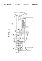
- FIG. 2 is a connection diagram of a CRT protector circuit according to the present invention.
- FIG. 3 is a flowchart illustrating the operation of the CRT protector circuit shown in FIG. 2.
- FIG. 2 shows a CRT protector circuit 50 according to the preferred embodiment of the present invention. Also in this preferred embodiment, a high-voltage generating operation similar to that in the related art mentioned above is performed, and a high voltage HV obtained by this generating operation is supplied to an anode 21 of a CRT 20 as similarly performed in the related art. Further, a detecting system for protecting the CRT 20 from an overvoltage or an overcurrent is also similar to that in the related art. Accordingly, the explanation of the parts substantially the same as those in the related art will be omitted hereinafter.
- an abnormal condition detected by a detector circuit 30 is transmitted to a control circuit 40 constructed as a microcomputer, and an operating condition of the control transistor Qb is controlled by an output from the control circuit 40.
- the control circuit 40 determines whether the abnormal condition detected by the detector circuit 30 is a temporary abnormal condition or a permanent abnormal condition, and controls the control transistor Qb either temporarily or permanently according to the result of determination.
- FIG. 3 is a flowchart showing the operation of the control circuit 40 in performing the above determination in a software controlled manner.
- a protector operation is performed at once (step 53).
- the protector operation in effect turns on the control transistor Qb and thereby stops the switching control of a horizontal output transistor Qa as mentioned above.
- a count-up (or count-down) operation is started, and the count value is compared with a predetermined value (steps 54 and 55).
- a numerical value such that there is no possibility of continuous generation of the temporary abnormal condition, is selected as the predetermined value.
- a numerical value of "3" is selected as the predetermined value in this preferred embodiment.
- the control transistor Qb is turned off to restore the normal high-voltage generating operation and resume this operation. Then, the abnormal condition detecting operation is ended, land the normal operation is automatically restored.
- Such a permanent abnormal condition may be visually informed the user by lighting an alarm lamp.
- the determination of whether the count value is less than the predetermined value may be effected by counting the frequency of the generation of the abnormal condition during a given period of time and then comparing the count value during this period of time with the predetermined time. In this case, when the given period of time elapses, a counter is automatically reset to restore an initial condition. Accordingly, even when the temporary abnormal condition is intermittently generated, it is possible to prevent the operation when the protector circuit will malfunction.
- the detection of the overvoltage may be effected by using a voltage detecting coil (tertiary coil) (not shown) provided in a flyback transformer 15.
- the numerical value selected as the predetermined value and the other limitations mentioned above are merely illustrative, and they may be adaptively decided. Further, a connecting position of the control transistor Qb is not limited to that shown.
- the CRT protector circuit can automatically determine whether the abnormal condition is a temporary abnormal condition, or a permanent abnormal condition and can automatically reset the protector operation to restore the normal condition when the abnormal condition is determined as the temporary abnormal condition.
- the present invention is greatly advantageous as a CRT protector circuit for use in a television receiver or the like.
Landscapes
- Engineering & Computer Science (AREA)
- Multimedia (AREA)
- Signal Processing (AREA)
- Details Of Television Scanning (AREA)
- Prevention Of Electric Corrosion (AREA)
- Protection Of Static Devices (AREA)
Applications Claiming Priority (2)
| Application Number | Priority Date | Filing Date | Title |
|---|---|---|---|
| JP5004245A JPH06217158A (ja) | 1993-01-13 | 1993-01-13 | Crt保護回路 |
| JP5-004245 | 1993-01-13 |
Publications (1)
| Publication Number | Publication Date |
|---|---|
| US5430596A true US5430596A (en) | 1995-07-04 |
Family
ID=11579162
Family Applications (1)
| Application Number | Title | Priority Date | Filing Date |
|---|---|---|---|
| US08/177,411 Expired - Fee Related US5430596A (en) | 1993-01-13 | 1994-01-05 | CRT protector circuit |
Country Status (7)
| Country | Link |
|---|---|
| US (1) | US5430596A (enExample) |
| JP (1) | JPH06217158A (enExample) |
| KR (1) | KR100282497B1 (enExample) |
| CN (1) | CN1075308C (enExample) |
| ES (1) | ES2080679B1 (enExample) |
| GB (1) | GB2274377B (enExample) |
| MY (1) | MY110589A (enExample) |
Cited By (14)
| Publication number | Priority date | Publication date | Assignee | Title |
|---|---|---|---|---|
| US5638245A (en) * | 1994-10-28 | 1997-06-10 | Daewoo Electronics Co., Ltd. | Electric power cut-off detection unit for a monitor |
| US5677731A (en) * | 1994-08-29 | 1997-10-14 | Matsushita Electric Industrial Co., Ltd. | Protective device and a television receiver provided with it |
| US5714843A (en) * | 1994-10-31 | 1998-02-03 | Samsung Electronicsco., Ltd. | CRT spot killer circuit responsive to loss of vertical synchronizing signal |
| US5883669A (en) * | 1994-07-08 | 1999-03-16 | Sony Corporation | Display device using electron beam and method of erasing display screen |
| US5900702A (en) * | 1996-05-02 | 1999-05-04 | Samsung Electronics Co., Ltd. | Oscillation voltage stabilizer |
| US6075687A (en) * | 1998-11-10 | 2000-06-13 | Mag Technology Co., Ltd. | Monitor X-ray protection device |
| US6122604A (en) * | 1996-12-02 | 2000-09-19 | Dynacolor Inc. | Digital protection circuit for CRT based display systems |
| US6188435B1 (en) * | 1997-03-11 | 2001-02-13 | Deutsche Thomson-Brandt Gmbh | Circuit for controlling beam current in a picture tube |
| US6282071B1 (en) * | 1999-11-08 | 2001-08-28 | Thomson Licensing, S.A. | Frequency dependent X-ray protection for a multimedia monitor |
| US6366035B1 (en) * | 2000-09-11 | 2002-04-02 | Mitsubishi Denki Kabushiki Kaisha | CRT display apparatus |
| US6577084B2 (en) * | 2000-10-18 | 2003-06-10 | Koninklijke Philips Electronics N.V. | High voltage flash detection |
| US20030197990A1 (en) * | 2002-04-19 | 2003-10-23 | Mitsuo Kumano | X-ray protector |
| US6812919B1 (en) * | 1996-08-30 | 2004-11-02 | Samsung Electronics Co., Ltd. | Display device with power interruption delay function |
| US20050001790A1 (en) * | 2003-07-03 | 2005-01-06 | Samsung Electronics Co., Ltd. | CRT display device and method |
Families Citing this family (3)
| Publication number | Priority date | Publication date | Assignee | Title |
|---|---|---|---|---|
| US6498630B1 (en) * | 1997-07-21 | 2002-12-24 | Stmicroelectronics Asia Pacific Pte Ltd. | X-ray protection circuit |
| JP2001326877A (ja) | 2000-05-18 | 2001-11-22 | Mitsubishi Electric Corp | ビデオプロジェクタのビーム電流制限回路 |
| CN100479490C (zh) * | 2004-12-09 | 2009-04-15 | Tcl王牌电子(深圳)有限公司 | 电视机显像管保护电路 |
Citations (5)
| Publication number | Priority date | Publication date | Assignee | Title |
|---|---|---|---|---|
| US4126816A (en) * | 1977-05-13 | 1978-11-21 | Rca Corporation | High voltage protection circuit |
| US4321513A (en) * | 1980-09-08 | 1982-03-23 | Rca Corporation | Television receiver high voltage protection circuit |
| EP0054452A1 (fr) * | 1980-12-12 | 1982-06-23 | Societe Electronique De La Region Pays De Loire | Dispositif de protection d'un récepteur de télévision, et téléviseur comportant un tel dispositif |
| US4441137A (en) * | 1982-08-30 | 1984-04-03 | Rca Corporation | High voltage protection for an output circuit |
| JPH02230871A (ja) * | 1989-03-03 | 1990-09-13 | Mitsubishi Electric Corp | X線プロテクター装置 |
Family Cites Families (2)
| Publication number | Priority date | Publication date | Assignee | Title |
|---|---|---|---|---|
| US4412254A (en) * | 1981-06-24 | 1983-10-25 | Rca Corporation | Television receiver high voltage protection circuit |
| GB9113924D0 (en) * | 1991-06-27 | 1991-08-14 | Thomson Consumer Electronics | Fault protection using microprocessor power up reset |
-
1993
- 1993-01-13 JP JP5004245A patent/JPH06217158A/ja active Pending
-
1994
- 1994-01-05 US US08/177,411 patent/US5430596A/en not_active Expired - Fee Related
- 1994-01-10 GB GB9400334A patent/GB2274377B/en not_active Expired - Fee Related
- 1994-01-11 MY MYPI94000064A patent/MY110589A/en unknown
- 1994-01-12 ES ES09400050A patent/ES2080679B1/es not_active Expired - Fee Related
- 1994-01-12 KR KR1019940000399A patent/KR100282497B1/ko not_active Expired - Fee Related
- 1994-01-13 CN CN94100723A patent/CN1075308C/zh not_active Expired - Fee Related
Patent Citations (5)
| Publication number | Priority date | Publication date | Assignee | Title |
|---|---|---|---|---|
| US4126816A (en) * | 1977-05-13 | 1978-11-21 | Rca Corporation | High voltage protection circuit |
| US4321513A (en) * | 1980-09-08 | 1982-03-23 | Rca Corporation | Television receiver high voltage protection circuit |
| EP0054452A1 (fr) * | 1980-12-12 | 1982-06-23 | Societe Electronique De La Region Pays De Loire | Dispositif de protection d'un récepteur de télévision, et téléviseur comportant un tel dispositif |
| US4441137A (en) * | 1982-08-30 | 1984-04-03 | Rca Corporation | High voltage protection for an output circuit |
| JPH02230871A (ja) * | 1989-03-03 | 1990-09-13 | Mitsubishi Electric Corp | X線プロテクター装置 |
Cited By (17)
| Publication number | Priority date | Publication date | Assignee | Title |
|---|---|---|---|---|
| US5883669A (en) * | 1994-07-08 | 1999-03-16 | Sony Corporation | Display device using electron beam and method of erasing display screen |
| US5677731A (en) * | 1994-08-29 | 1997-10-14 | Matsushita Electric Industrial Co., Ltd. | Protective device and a television receiver provided with it |
| US5638245A (en) * | 1994-10-28 | 1997-06-10 | Daewoo Electronics Co., Ltd. | Electric power cut-off detection unit for a monitor |
| US5714843A (en) * | 1994-10-31 | 1998-02-03 | Samsung Electronicsco., Ltd. | CRT spot killer circuit responsive to loss of vertical synchronizing signal |
| US5900702A (en) * | 1996-05-02 | 1999-05-04 | Samsung Electronics Co., Ltd. | Oscillation voltage stabilizer |
| US6812919B1 (en) * | 1996-08-30 | 2004-11-02 | Samsung Electronics Co., Ltd. | Display device with power interruption delay function |
| US6122604A (en) * | 1996-12-02 | 2000-09-19 | Dynacolor Inc. | Digital protection circuit for CRT based display systems |
| US6188435B1 (en) * | 1997-03-11 | 2001-02-13 | Deutsche Thomson-Brandt Gmbh | Circuit for controlling beam current in a picture tube |
| US6075687A (en) * | 1998-11-10 | 2000-06-13 | Mag Technology Co., Ltd. | Monitor X-ray protection device |
| US6282071B1 (en) * | 1999-11-08 | 2001-08-28 | Thomson Licensing, S.A. | Frequency dependent X-ray protection for a multimedia monitor |
| KR100394883B1 (ko) * | 2000-09-11 | 2003-08-19 | 미쓰비시덴키 가부시키가이샤 | Crt 표시 장치 |
| US6366035B1 (en) * | 2000-09-11 | 2002-04-02 | Mitsubishi Denki Kabushiki Kaisha | CRT display apparatus |
| US6577084B2 (en) * | 2000-10-18 | 2003-06-10 | Koninklijke Philips Electronics N.V. | High voltage flash detection |
| US20030197990A1 (en) * | 2002-04-19 | 2003-10-23 | Mitsuo Kumano | X-ray protector |
| US7054125B2 (en) * | 2002-04-19 | 2006-05-30 | Orion Electric Co., Ltd. | X-ray protector |
| US20050001790A1 (en) * | 2003-07-03 | 2005-01-06 | Samsung Electronics Co., Ltd. | CRT display device and method |
| US7236145B2 (en) | 2003-07-03 | 2007-06-26 | Samsung Electronics Co., Ltd. | CRT display device and method |
Also Published As
| Publication number | Publication date |
|---|---|
| GB9400334D0 (en) | 1994-03-09 |
| GB2274377A (en) | 1994-07-20 |
| ES2080679A2 (es) | 1996-02-01 |
| JPH06217158A (ja) | 1994-08-05 |
| KR100282497B1 (ko) | 2001-02-15 |
| CN1093848A (zh) | 1994-10-19 |
| GB2274377B (en) | 1996-08-21 |
| ES2080679R (enExample) | 1997-07-01 |
| MY110589A (en) | 1998-08-29 |
| CN1075308C (zh) | 2001-11-21 |
| ES2080679B1 (es) | 1998-02-16 |
Similar Documents
| Publication | Publication Date | Title |
|---|---|---|
| US5430596A (en) | CRT protector circuit | |
| KR100298960B1 (ko) | 마이크로프로세서의파워업리세트기능을이용한고장보호장치 | |
| JP3784838B2 (ja) | スイッチ電源 | |
| JP3880071B2 (ja) | 電源 | |
| US4788618A (en) | High voltage protecting circuit | |
| RU2407212C2 (ru) | Схема подавления повышения напряжения и панельный телевизионный приемник | |
| JPS639790B2 (enExample) | ||
| US5621632A (en) | Switch mode power supply circuit | |
| JPH0582110B2 (enExample) | ||
| US4905116A (en) | X-radiation protection circuit | |
| JP3236319B2 (ja) | エックス線保護回路 | |
| JP2522588Y2 (ja) | 過電流及び過電圧保護回路 | |
| JPH01108870A (ja) | 保護回路 | |
| KR0142718B1 (ko) | 텔레비전의 쇼트 프로텍트 지연회로 | |
| US5255147A (en) | Vertical yoke protection system | |
| KR0143717B1 (ko) | 에프비티의 과부하 방지회로 | |
| KR910008275Y1 (ko) | 텔레비젼의 x선 방출 방지회로 | |
| EP0434075A1 (en) | Vertical yoke protection system | |
| KR0175803B1 (ko) | 모니터의 오동작 방지회로 | |
| KR100374583B1 (ko) | 텔레비전의고압상승억제보호장치 | |
| JPH0215419Y2 (enExample) | ||
| KR910000652Y1 (ko) | X-레이 방지회로 | |
| EP0870397B1 (en) | Over-current protection circuit in line deflection circuits | |
| KR200234417Y1 (ko) | 관내방전시 커패시터 보호기능을 구비한 플라이백트랜스포머 | |
| JPH0471325A (ja) | 高圧発生回路 |
Legal Events
| Date | Code | Title | Description |
|---|---|---|---|
| AS | Assignment |
Owner name: SONY CORPORATION, JAPAN Free format text: ASSIGNMENT OF ASSIGNORS INTEREST;ASSIGNORS:HAMAGUCHI, KENJI;OGISHIMA, KIYOSHI;REEL/FRAME:006982/0554;SIGNING DATES FROM 19940307 TO 19940310 |
|
| FEPP | Fee payment procedure |
Free format text: PAYOR NUMBER ASSIGNED (ORIGINAL EVENT CODE: ASPN); ENTITY STATUS OF PATENT OWNER: LARGE ENTITY |
|
| FPAY | Fee payment |
Year of fee payment: 4 |
|
| REMI | Maintenance fee reminder mailed | ||
| LAPS | Lapse for failure to pay maintenance fees | ||
| STCH | Information on status: patent discontinuation |
Free format text: PATENT EXPIRED DUE TO NONPAYMENT OF MAINTENANCE FEES UNDER 37 CFR 1.362 |
|
| FP | Lapsed due to failure to pay maintenance fee |
Effective date: 20030704 |