US5356336A - Nozzle for discharging air and method - Google Patents
Nozzle for discharging air and method Download PDFInfo
- Publication number
- US5356336A US5356336A US08/087,368 US8736893A US5356336A US 5356336 A US5356336 A US 5356336A US 8736893 A US8736893 A US 8736893A US 5356336 A US5356336 A US 5356336A
- Authority
- US
- United States
- Prior art keywords
- intruder
- grill
- air
- axial center
- nozzle
- Prior art date
- Legal status (The legal status is an assumption and is not a legal conclusion. Google has not performed a legal analysis and makes no representation as to the accuracy of the status listed.)
- Expired - Fee Related
Links
Images


Classifications
-
- F—MECHANICAL ENGINEERING; LIGHTING; HEATING; WEAPONS; BLASTING
- F24—HEATING; RANGES; VENTILATING
- F24F—AIR-CONDITIONING; AIR-HUMIDIFICATION; VENTILATION; USE OF AIR CURRENTS FOR SCREENING
- F24F13/00—Details common to, or for air-conditioning, air-humidification, ventilation or use of air currents for screening
- F24F13/08—Air-flow control members, e.g. louvres, grilles, flaps or guide plates
- F24F13/081—Air-flow control members, e.g. louvres, grilles, flaps or guide plates for guiding air around a curve
-
- B—PERFORMING OPERATIONS; TRANSPORTING
- B60—VEHICLES IN GENERAL
- B60H—ARRANGEMENTS OF HEATING, COOLING, VENTILATING OR OTHER AIR-TREATING DEVICES SPECIALLY ADAPTED FOR PASSENGER OR GOODS SPACES OF VEHICLES
- B60H1/00—Heating, cooling or ventilating [HVAC] devices
- B60H1/34—Nozzles; Air-diffusers
- B60H1/3414—Nozzles; Air-diffusers with means for adjusting the air stream direction
- B60H1/3435—Nozzles; Air-diffusers with means for adjusting the air stream direction using only a pivoting frame
Definitions
- This invention relates to a nozzle for discharging air from an air supply into an enclosed space, such as a room, or to a vehicle interior, having a control device for controlling deflection of air from the nozzle through a grill having a high degree of visual opacity to obscure elements behind the grill while maintaining a high face velocity and without significantly affecting or impairing deflection of the air stream as imparted thereto by the upstream intruder control member.
- An object of the present invention is to provide an improved air discharge nozzle, and, especially a discharge nozzle, particularly useful for vehicle interiors.
- a specific object of the invention is to provide an air discharge nozzle and method for vehicles having a grill which has a high degree of visual opacity to enhance design aesthetics, low impedance so that the face velocity remains high, and which does not significantly affect directionality of the air as imparted to the air stream by an upstream control mechanism and which, preferably, can be molded.
- Another specific object of the invention is to provide an improved directionality control mechanism.
- the grill is comprised of a monolayer of polygonal cells in an array of cells, each cell being bounded by planar walls having a depth "L" interstitial thickness "T” and a diameter or major dimension "D", wherein the interstitial depth L is short enough such that the planar walls do not act as vanes to significantly affect directionality of the air as imparted by the upstream directionality control mechanism, the interstitial thickness T has a value such that the impedance to air flow is low and the ratio of T/D is such that there is low friction losses at the grill and the length to diameter ratio L/D is no greater than about 0.7 and no less than about 0.3, such that the relative visual opacity of the grill when viewed from any angle is high.
- the depth L is no greater than about 5 times the interstitial thickness T.
- the open cell area Ao must be at least about 76% of the available (total) area to obtain an acceptable 1800 ft/min face velocity at a blower pressure of 0.24 inches H 2 O.
- visual opacity ranges from 0 percent for an open nozzle (e.g. no grill) to where the grill is in place 24 percent is obscured when the observer is looking directly on the cells and the observer's viewing angle changes from an axial alignment with the cells and becomes more and more visually opaque to where, in the case of the L/D ratio of 0.67 or a 56 degree viewing angle equals 100 percent opacity.
- the upstream directionality control mechanism includes, in a preferred embodiment, an open intruder frame having an upstream bounding edge joined to its downstream boundary edge by converging walls so that the cross-sectional area of the total shadow area of the frame projected on a plane normal to the axial center is essentially constant so that the impedance to air flow is essentially constant.
- a cross member joined to the frame member has an axially projecting control shaft which carries a spherical member frictionally received in a spherical socket formed in the grill such that the control shaft can easily be manually manipulated. When the end of the shaft projects beyond the grill in the form of a control knob, the knob points in the direction the air is caused to flow.
- the intruder is an open frame, the amount of angular movement of the control shaft is significantly reduced.
- the intruder member is a small area disk on the upstream end of the control shaft.
- FIG. 1a is an isometric illustration of a vehicular air discharge nozzle incorporating the invention
- FIGS. 1b and 1c are similar views broken away to reveal the intruder
- FIG. 2 is a sectional view of the air discharge nozzle shown in FIGS. 1a-c,
- FIGS. 3a, 3b, 3c, and 3d are examples of grill cell patterns
- FIG. 4 is a graph showing the result of tests of percent open cell area versus peak face velocity in feet per minute
- FIG. 5 shows the effect of the cell L/D ratio on the ability to deflect the air stream and is a graph of the ratio of the deflection angle with grill to the deflection without grill plotted against the cell depth/diameter (L/D) ratio
- FIG. 6 is a plot of relative opacity vs. viewing angle for various L/D ratios
- FIG. 7 is an isometric view of a further embodiment of an air flow outlet incorporating the invention.
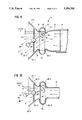
- FIG. 8 is a diagrammatic sectional view of the embodiment shown in FIG. 7 showing the intruder member centrally and coaxially located to direct the main air flow vector directly outwardly,
- FIG. 9 is a diagrammatic sectional view of the embodiment of FIG. 7 showing the intruder member which has been positioned offset from the axial center so that the main air flow vector is directed at an angle to an axis line through the axial center,
- FIG. 10 is a diagrammatic sectional view of a modification of the outlet shown in FIG. 7 with a further modification of the intruder member, and
- FIG. 11 is a view similar to FIG. 2 showing the use of the disc intruder member with the novel grill structure disclosed herein.
- a nozzle 10 incorporating the invention has an upstream end 11 coupled to an air supply duct 12.
- the duct is rectangular, but it could be circular or oval in cross-section.
- Diverging top 14, bottom 15, sides 16 and 17 form the downstream outlet which is closed off by grill 20, which is formed of a monolayer of polygonal cells (hexagonal) in an array of cells bounded by planar walls 21 having a depth L, an interstitial thickness T, and a major diameter D.
- the grill 20 is mounted to close off the downstream outlet end by an annular rim 22, but could be part of a larger molding having other functional attributes with the downstream outlet end secured by fasteners or adhesive, etc. (not shown).
- open frame intruder member 30 which in the embodiment illustrated, is rectangular, having top and bottom intruder members 31 and 32 and side intruder members 33 and 34 to form an endless open frame.
- Intruder members 31, 32, 33 and 34 converge slightly from their upstream edges to their downstream edges so that, within limits, regardless of the angular orientation of the open frame of intruder 30 to the axial center AC, its cross-sectional area projected on a plane normal to the axial center AC, is essentially constant to where one of the members 31 or 32 and one of members 33 or 34 is parallel to the axial center (see the phantom position in FIG. 2). As one member projects a larger area on the plane, the other member casts or projects a correspondingly smaller area, thereby maintaining the impedance essentially constant.
- each intruder member is spaced from the axial center when the open frame intruder is centered (and not causing any air deflection, the amount of movement of the control shaft 35 is significantly less than the case where a single intruder member is swinging from one boundary wall to the other).
- the benefits of the grill features discussed earlier herein are just as applicable to single intruder members as to the open frame intruder member.
- a cross member 36 secures the upstream intruder 30 to the upstream end of control shaft 35.
- a spherical ball 37 on shaft 35 is received in split spherical socket 38 which is formed, preferably, in the axial center of grill 20, and a manual control knob 40 is formed on the end of shaft 35.
- the members 31, 32, 33, 34 of the intruder 30 operate in conjunction with a respective side of the nozzle which it is directed to approaches to direct the air flow to the opposite side, as shown in phantom or dashed lines in FIG. 2, which corresponds with the direction of deflection of the intruder 20 shown in FIG. 1c.In FIGS. 1a and 1c, the intruder is axially centered so there is no deflection. This construction provides for up, down, left and right deflections as well as those in between. Instead of knob 40 or spherical surface with a bump to indicate the axial center, and manipulated by a thumb or index finger.
- An acceptable face velocity is in the order of 1800 ft/min which corresponds to an open cell area of about 76% in the graph of FIG. 4.
- the next parameter to consider is the effect of cell L/D on the ability to deflect the stream. That is, the cell should be thin enough in depth to not redirect the deflected airstream.
- the test results are shown in FIG. 5 where the ratio of the deflection angle with grill to the deflection angle without grill is plotted against the cell depth/diameter (L/D).
- a L/D ratio up to 0.6 may be used to obtain an acceptable deflection angle. If the cell is deeper, i.e., L/D>0.6, then the deflection is impaired by the grill.
- the open cell area Ao is preferably at least about 76% of the available (total) area to obtain an acceptable 1800 ft/min face velocity at blower pressure of 0.24 inches H 2 O. Mathematically stated this is: ##EQU1##
- FIGS. 3a-3b Various cell geometries are shown in FIGS. 3a-3b.
- FIG. 3a shows a cell array wherein the cells are diamond-shaped and the major diameter is the largest diameter; in FIG. 3b.
- FIGS. 3b-3d show various forms of essentially square cell patterns where the major diameter D is an average of cell diameters. While a triangular cell pattern could be used, this is a less preferred embodiment of the invention.
- the invention uses a disc.
- the air flow outlet has an inlet opening or nozzle with a central axial axis joined to a larger area outlet opening by a cusp region and diverging short walls.
- the upstream intruder deflector member is a small disc or plate which, like the frame intruder shown in FIGS. 1b, 1c and 2, has a surface area which is a small fraction of the surface area of the inlet opening.
- the disc has an axial center which, when aligned with the axial center of the inlet opening, causes air flow substantially uniformly around all sides of the intruder or barrier member, but when the axial center of the intruder or barrier member is offset from the axial center of the intruder or barrier member, air flows on the opposite side from the direction of offset and, in conjunction with cusp region and the diverging sidewalls on that opposite side, causes the air to flow in a deflected direction which is at an angle to an axis passing through the axial center of the inlet and outlet opening.
- the cusp or space region bounds the perimeter of the inlet opening or nozzle and when the intruder member is axially aligned, normal wall attachment effects are minimized by the cusp region and an offset.
- the intruder is on a shaft which is mounted by a universal joint in the axial center of the outlet opening such that the direction of orientation of the shaft points substantially in the direction of air flow.
- the intruder member could be mounted on a planar frame which is translatable in its plane by an adjustment mechanism to adjust the position of the intruder relative to the central axis of the inlet opening.
- the disc intruder member can be used in place of the preferred frame intruder member grille shown in the earlier embodiments.
- an air flow outlet 110 incorporating the invention is attached to a duct 111, which is connected to a supply of air under pressure, such as a vehicle air heater and air conditioner supply.
- the input portion 112 converges to a nozzle 113 which, as shown in FIG. 7 is slightly rectangular, but could be square, circular or oval in shape.
- a cusp forming portion or region 114 is connected between nozzle 113 and short diverging walls 115-1, 115-2, 115-3 and 115-4 which have upstream ends 16 which are offset a distance D from the nozzle 113.
- the offset, cusp region, short length of the walls 115 and the angle of wall divergence are sufficient to preclude any significant wall attachment effects to walls 115-1, 115-2, 115-3 and 115-4 when the control intruder disc 117 is centrally positioned and axially aligned as shown in FIG. 8 so that air has a main flow vector 118, which is axially aligned with the axis of the input portion 112.
- Cusp 114 optionally may include baffle members 119-1, 119-2, 119-3 and 119-4 so as to substantially preclude circumferential flow of air and improve performance.
- Control intruder member 117 is mounted on control shaft 120 which has a mounting ball 121 supported from a spherical socket 122, which, in turn is supported by spider legs 123-1, 123-2, 123-3 and 123-4, whose respective ends are secured to or formed with diverging walls 15-1, 115-2, 115-3 and 115-4, respectively.
- intruder disc member 117 is constituted by a pair of intruder plates 124, 125, plate 125 being smaller in diameter than plate 124 so as to present a stepped intruder member to air flow when in the position shown in FIG. 8.
- the intruder member has a small area (in its largest dimension plate) relative to the area of the inlet nozzle 13 (5 to 30% are preferable ratios, but other ratios may be found useful).
- circular intruder members are shown, it will be appreciated that oval and rectangular intruder plates may be used if desired.
- a knob 125 on the end of control shaft 120 may be provided, but for some aesthetic circumstances, it may be desirable to avoid any projections beyond the ends of the diverging walls 115-1, 115-2, 115-3 and 115-4 so the control will be merely adjusting sphere 121 in spherical socket 122 (in the fashion of a computer trackball).
- the intruder member could be a plate having a perimetrical shape corresponding to the shape of outlet nozzle 113 held by a spider frame and translatable in its plane by a gear or linkage adjustment mechanism and the control shaft and spherical ball mount eliminated.
- the stacked plate intruder member has been replaced by a single plate 24' and the main air flow vector 130 is illustrated as being partially deflected toward short wall 115-4.
- FIG. 11 shows an air outlet nozzle 10' with a grill structure 21' as described earlier herein and an upstream deflection system comprised of a disc intruder 224 on the upstream end of control shaft 35'.
- Disc intruder 224 has an area which is substantially less than 50% of the duct opening, and preferably in the range of 5% to about 30% of the open area of said duct.
Landscapes
- Engineering & Computer Science (AREA)
- Mechanical Engineering (AREA)
- Physics & Mathematics (AREA)
- Thermal Sciences (AREA)
- General Engineering & Computer Science (AREA)
- Combustion & Propulsion (AREA)
- Chemical & Material Sciences (AREA)
- Air-Flow Control Members (AREA)
- Duct Arrangements (AREA)
- Telephone Function (AREA)
- Jet Pumps And Other Pumps (AREA)
- Electrical Discharge Machining, Electrochemical Machining, And Combined Machining (AREA)
- Application Of Or Painting With Fluid Materials (AREA)
- Secondary Cells (AREA)
Priority Applications (1)
| Application Number | Priority Date | Filing Date | Title |
|---|---|---|---|
| US08/087,368 US5356336A (en) | 1992-03-17 | 1993-07-08 | Nozzle for discharging air and method |
Applications Claiming Priority (3)
| Application Number | Priority Date | Filing Date | Title |
|---|---|---|---|
| US85323692A | 1992-03-17 | 1992-03-17 | |
| US08/003,702 US5297989A (en) | 1993-01-13 | 1993-01-13 | Nozzle for discharging air and method |
| US08/087,368 US5356336A (en) | 1992-03-17 | 1993-07-08 | Nozzle for discharging air and method |
Related Parent Applications (2)
| Application Number | Title | Priority Date | Filing Date |
|---|---|---|---|
| US85323692A Continuation-In-Part | 1992-03-17 | 1992-03-17 | |
| US08/003,702 Continuation-In-Part US5297989A (en) | 1992-03-17 | 1993-01-13 | Nozzle for discharging air and method |
Publications (1)
| Publication Number | Publication Date |
|---|---|
| US5356336A true US5356336A (en) | 1994-10-18 |
Family
ID=26672076
Family Applications (1)
| Application Number | Title | Priority Date | Filing Date |
|---|---|---|---|
| US08/087,368 Expired - Fee Related US5356336A (en) | 1992-03-17 | 1993-07-08 | Nozzle for discharging air and method |
Country Status (10)
| Country | Link |
|---|---|
| US (1) | US5356336A (de) |
| EP (1) | EP0630328B1 (de) |
| JP (1) | JPH07504632A (de) |
| AT (1) | ATE174556T1 (de) |
| AU (1) | AU665321B2 (de) |
| BR (1) | BR9306093A (de) |
| CA (1) | CA2131724C (de) |
| DE (1) | DE69322625T2 (de) |
| ES (1) | ES2128420T3 (de) |
| WO (1) | WO1993018931A1 (de) |
Cited By (26)
| Publication number | Priority date | Publication date | Assignee | Title |
|---|---|---|---|---|
| US5788394A (en) * | 1997-04-23 | 1998-08-04 | Bowles Fluidics Corporation | Grooved ball and socket joint |
| WO1998036927A2 (en) | 1997-02-25 | 1998-08-27 | Bowles Fluidics Corporation | Vehicle air outlet with combined flow straightener and shutoff door |
| WO1999007569A1 (fr) * | 1997-08-04 | 1999-02-18 | M.G.I. Coutier S.A. | Dispositif d'aeration pour un vehicule automobile |
| FR2772311A1 (fr) * | 1997-12-16 | 1999-06-18 | Coutier Moulage Gen Ind | Dispositif d'aeration pour un vehicule automobile |
| US6159092A (en) * | 1998-08-31 | 2000-12-12 | Fickenscher America, L.L.C. | Air vent having two coplanar vane sets |
| US6776710B1 (en) * | 2003-10-24 | 2004-08-17 | Unico, Inc. | Vent structure for slotted outlet with uniform velocity profile |
| US20040224625A1 (en) * | 2003-03-03 | 2004-11-11 | Trw Automotive Electronics & Components Gmbh & Co. Kg | Air vent for a ventilation system |
| US20060234622A1 (en) * | 2005-03-31 | 2006-10-19 | Holyoake Scott N | Air flow control device |
| US20070066212A1 (en) * | 2003-11-13 | 2007-03-22 | Behr Gmbh & Co. Kg | Nozzle array, especially for a motor vehicle |
| US20080014855A1 (en) * | 2004-06-24 | 2008-01-17 | Faurecia Interieur Industrie | Fan |
| US20100068982A1 (en) * | 2006-06-16 | 2010-03-18 | Faurecia Interieur Industrie | Forced ventilation system for the passenger compartment of an automobile, and corresponding dashboard |
| DE102009026768A1 (de) * | 2009-06-05 | 2010-12-16 | Caverion Gmbh | Luftdurchlass |
| US20110217914A1 (en) * | 2010-03-05 | 2011-09-08 | GM Global Technology Operations LLC | Ventilation nozzle for the interior of a vehicle |
| US20130012115A1 (en) * | 2011-07-05 | 2013-01-10 | Rochling Automotive Ag & Co. Kg | Air Guiding Device for a Motor Vehicle |
| US9341386B2 (en) * | 2012-10-23 | 2016-05-17 | GM Global Technology Operations LLC | Vehicular airflow outlet |
| US20160152116A1 (en) * | 2014-12-02 | 2016-06-02 | GM Global Technology Operations LLC | Air vent for a vehicle |
| US9513027B2 (en) | 2013-05-29 | 2016-12-06 | Faurecia Innenraum Systeme Gmbh | Air vent |
| US20170176046A1 (en) * | 2014-08-07 | 2017-06-22 | GRAMMER Interior Components GmbH | Ventilation device |
| US20170190240A1 (en) * | 2015-12-30 | 2017-07-06 | Faurecia Innenraum Systeme Gmbh | Outlet device |
| US20170225545A1 (en) * | 2016-02-10 | 2017-08-10 | Kabushiki Kaisha Toyota Jidoshokki | Register and vehicle |
| US20170326951A1 (en) * | 2016-05-10 | 2017-11-16 | GM Global Technology Operations LLC | Air outlet for arrangement in the passenger compartment of a motor vehicle |
| CN108215722A (zh) * | 2016-12-21 | 2018-06-29 | 现代自动车株式会社 | 用于调节机动车辆的细长型通风口的气流方向的装置 |
| US10195924B2 (en) | 2013-05-29 | 2019-02-05 | Faurecia Innenraum Systeme Gmbh | Air vent |
| DE102018127506A1 (de) * | 2018-11-05 | 2020-05-07 | Bayerische Motoren Werke Aktiengesellschaft | Luftausströmer für einen Kraftwagen, insbesondere für einen Personenkraftwagen, sowie Kraftwagen |
| US11207950B2 (en) * | 2019-07-05 | 2021-12-28 | Fischer Automotive Systems Gmbh & Co. Kg | Air vent |
| US11458815B2 (en) * | 2019-07-05 | 2022-10-04 | Fischer Automotive Systems Gmbh & Co. Kg | Air vent |
Families Citing this family (7)
| Publication number | Priority date | Publication date | Assignee | Title |
|---|---|---|---|---|
| FR2710880B1 (fr) * | 1993-10-07 | 1995-11-24 | Valeo Thermique Habitacle | Buse de soufflage pour un appareil de chauffage-ventilation et/ou de climatisation de l'habitacle d'un véhicule automobile. |
| DE19648736C1 (de) * | 1996-11-25 | 1998-01-15 | Daimler Benz Ag | Belüftungsdüse |
| AU2005242179B2 (en) * | 2004-12-10 | 2010-10-28 | Valentino Fuda | Paint roller tray |
| DE102006053836A1 (de) * | 2006-11-14 | 2008-05-15 | Behr Gmbh & Co. Kg | Luftausströmer mit Drallströmung und konventioneller Strömung |
| DE102006054847A1 (de) * | 2006-11-20 | 2008-05-21 | Behr Gmbh & Co. Kg | Luftausströmer mit einem Einsatz aus verformbaren Material |
| JP5529564B2 (ja) * | 2010-01-29 | 2014-06-25 | 豊和化成株式会社 | レジスタ |
| DE102011110700A1 (de) * | 2011-08-16 | 2013-02-21 | GM Global Technology Operations LLC (n. d. Gesetzen des Staates Delaware) | Luftausströmeinrichtung für den Kraftfahrzeug-Innenraum |
Citations (13)
| Publication number | Priority date | Publication date | Assignee | Title |
|---|---|---|---|---|
| US3200734A (en) * | 1963-05-08 | 1965-08-17 | Pyle National Co | Combination acoustic ceiling panel and air diffuser |
| US3356006A (en) * | 1965-10-18 | 1967-12-05 | Robert D Scott | Clean room structure |
| US3548735A (en) * | 1969-01-14 | 1970-12-22 | Aeronca Inc | Air distributor |
| JPS5468034A (en) * | 1977-11-08 | 1979-05-31 | Matsushita Electric Ind Co Ltd | Air conditioner |
| JPS54108323A (en) * | 1978-02-13 | 1979-08-24 | Matsushita Electric Ind Co Ltd | Air blow-off device for vehicles |
| US4556172A (en) * | 1982-05-25 | 1985-12-03 | Matsushita Electric Industrial Co. Ltd. | Flow direction controller |
| JPS6138347A (ja) * | 1984-07-30 | 1986-02-24 | Toyoda Gosei Co Ltd | 給気グリル |
| JPS61195235A (ja) * | 1985-02-26 | 1986-08-29 | Matsushita Electric Ind Co Ltd | 流れ方向制御装置 |
| US4664022A (en) * | 1985-04-16 | 1987-05-12 | Itw Fastex Italia S.P.A. | Perfected air inlet |
| US4669370A (en) * | 1985-03-21 | 1987-06-02 | Siemens Aktiengesellschaft | Air flow guide assembly in automotive ventilating system |
| US4702155A (en) * | 1985-03-21 | 1987-10-27 | Siemens Aktiengesellschaft | Air guide assembly in automotive ventilating system |
| JPS62294844A (ja) * | 1987-04-28 | 1987-12-22 | Matsushita Electric Ind Co Ltd | 流れ方向制御装置 |
| EP0251307A2 (de) * | 1986-07-02 | 1988-01-07 | Matsushita Electric Industrial Co., Ltd. | Vorrichtung zum Ablenken einer Strömung |
-
1993
- 1993-03-17 CA CA002131724A patent/CA2131724C/en not_active Expired - Fee Related
- 1993-03-17 AT AT93907396T patent/ATE174556T1/de not_active IP Right Cessation
- 1993-03-17 ES ES93907396T patent/ES2128420T3/es not_active Expired - Lifetime
- 1993-03-17 DE DE69322625T patent/DE69322625T2/de not_active Expired - Fee Related
- 1993-03-17 WO PCT/US1993/002183 patent/WO1993018931A1/en active IP Right Grant
- 1993-03-17 AU AU38016/93A patent/AU665321B2/en not_active Ceased
- 1993-03-17 EP EP93907396A patent/EP0630328B1/de not_active Expired - Lifetime
- 1993-03-17 BR BR9306093A patent/BR9306093A/pt not_active IP Right Cessation
- 1993-03-17 JP JP5516610A patent/JPH07504632A/ja active Pending
- 1993-07-08 US US08/087,368 patent/US5356336A/en not_active Expired - Fee Related
Patent Citations (13)
| Publication number | Priority date | Publication date | Assignee | Title |
|---|---|---|---|---|
| US3200734A (en) * | 1963-05-08 | 1965-08-17 | Pyle National Co | Combination acoustic ceiling panel and air diffuser |
| US3356006A (en) * | 1965-10-18 | 1967-12-05 | Robert D Scott | Clean room structure |
| US3548735A (en) * | 1969-01-14 | 1970-12-22 | Aeronca Inc | Air distributor |
| JPS5468034A (en) * | 1977-11-08 | 1979-05-31 | Matsushita Electric Ind Co Ltd | Air conditioner |
| JPS54108323A (en) * | 1978-02-13 | 1979-08-24 | Matsushita Electric Ind Co Ltd | Air blow-off device for vehicles |
| US4556172A (en) * | 1982-05-25 | 1985-12-03 | Matsushita Electric Industrial Co. Ltd. | Flow direction controller |
| JPS6138347A (ja) * | 1984-07-30 | 1986-02-24 | Toyoda Gosei Co Ltd | 給気グリル |
| JPS61195235A (ja) * | 1985-02-26 | 1986-08-29 | Matsushita Electric Ind Co Ltd | 流れ方向制御装置 |
| US4669370A (en) * | 1985-03-21 | 1987-06-02 | Siemens Aktiengesellschaft | Air flow guide assembly in automotive ventilating system |
| US4702155A (en) * | 1985-03-21 | 1987-10-27 | Siemens Aktiengesellschaft | Air guide assembly in automotive ventilating system |
| US4664022A (en) * | 1985-04-16 | 1987-05-12 | Itw Fastex Italia S.P.A. | Perfected air inlet |
| EP0251307A2 (de) * | 1986-07-02 | 1988-01-07 | Matsushita Electric Industrial Co., Ltd. | Vorrichtung zum Ablenken einer Strömung |
| JPS62294844A (ja) * | 1987-04-28 | 1987-12-22 | Matsushita Electric Ind Co Ltd | 流れ方向制御装置 |
Non-Patent Citations (2)
| Title |
|---|
| "Improved Ventilating Register", Iron Age, Aug. 23, 1988 p. 296. |
| Improved Ventilating Register , Iron Age, Aug. 23, 1988 p. 296. * |
Cited By (43)
| Publication number | Priority date | Publication date | Assignee | Title |
|---|---|---|---|---|
| EP0964796A4 (de) * | 1997-02-25 | 2000-12-27 | Bowles Fluidics Corp | Luftauslass für krafthahrzeug mit kombiniertem strömungsgleichrichter und verschlussklappe |
| WO1998036927A2 (en) | 1997-02-25 | 1998-08-27 | Bowles Fluidics Corporation | Vehicle air outlet with combined flow straightener and shutoff door |
| US5816907A (en) * | 1997-02-25 | 1998-10-06 | Bowles Fluidics Corporation | Vehicle air outlet with combined flow straightener and shutoff door |
| EP0964796A2 (de) * | 1997-02-25 | 1999-12-22 | Bowles Fluidics Corporation | Luftauslass für krafthahrzeug mit kombiniertem strömungsgleichrichter und verschlussklappe |
| AU722893B2 (en) * | 1997-02-25 | 2000-08-10 | Bowles Fluidics Corporation | Vehicle air outlet with combined flow straightener and shutoff door |
| US5788394A (en) * | 1997-04-23 | 1998-08-04 | Bowles Fluidics Corporation | Grooved ball and socket joint |
| WO1999007569A1 (fr) * | 1997-08-04 | 1999-02-18 | M.G.I. Coutier S.A. | Dispositif d'aeration pour un vehicule automobile |
| FR2772311A1 (fr) * | 1997-12-16 | 1999-06-18 | Coutier Moulage Gen Ind | Dispositif d'aeration pour un vehicule automobile |
| US6159092A (en) * | 1998-08-31 | 2000-12-12 | Fickenscher America, L.L.C. | Air vent having two coplanar vane sets |
| US20040224625A1 (en) * | 2003-03-03 | 2004-11-11 | Trw Automotive Electronics & Components Gmbh & Co. Kg | Air vent for a ventilation system |
| US7201650B2 (en) * | 2003-03-03 | 2007-04-10 | Trw Automotive Electronics & Components Gmbh & Co. Kg | Air vent for a ventilation system |
| US6776710B1 (en) * | 2003-10-24 | 2004-08-17 | Unico, Inc. | Vent structure for slotted outlet with uniform velocity profile |
| US20070066212A1 (en) * | 2003-11-13 | 2007-03-22 | Behr Gmbh & Co. Kg | Nozzle array, especially for a motor vehicle |
| JP2007511401A (ja) * | 2003-11-13 | 2007-05-10 | ベール ゲーエムベーハー ウント コー カーゲー | 特に自動車用のノズル装置 |
| JP4664922B2 (ja) * | 2003-11-13 | 2011-04-06 | ベール ゲーエムベーハー ウント コー カーゲー | 特に自動車用のノズル装置 |
| US20080014855A1 (en) * | 2004-06-24 | 2008-01-17 | Faurecia Interieur Industrie | Fan |
| US20060234622A1 (en) * | 2005-03-31 | 2006-10-19 | Holyoake Scott N | Air flow control device |
| US20100068982A1 (en) * | 2006-06-16 | 2010-03-18 | Faurecia Interieur Industrie | Forced ventilation system for the passenger compartment of an automobile, and corresponding dashboard |
| DE102009026768B4 (de) * | 2009-06-05 | 2012-04-05 | Yit Germany Gmbh | Luftdurchlass |
| DE102009026768A1 (de) * | 2009-06-05 | 2010-12-16 | Caverion Gmbh | Luftdurchlass |
| US20110217914A1 (en) * | 2010-03-05 | 2011-09-08 | GM Global Technology Operations LLC | Ventilation nozzle for the interior of a vehicle |
| US10160309B2 (en) * | 2011-07-05 | 2018-12-25 | Röchling Automotive SE & Co. KG | Air guiding device for a motor vehicle |
| US20130012115A1 (en) * | 2011-07-05 | 2013-01-10 | Rochling Automotive Ag & Co. Kg | Air Guiding Device for a Motor Vehicle |
| US9341386B2 (en) * | 2012-10-23 | 2016-05-17 | GM Global Technology Operations LLC | Vehicular airflow outlet |
| US11878573B2 (en) | 2013-05-29 | 2024-01-23 | Faurecia Innenraum Systeme Gmbh | Air vent |
| US9513027B2 (en) | 2013-05-29 | 2016-12-06 | Faurecia Innenraum Systeme Gmbh | Air vent |
| US11400795B2 (en) | 2013-05-29 | 2022-08-02 | Faurecia Innenraum Systeme Gmbh | Air vent |
| US10408490B2 (en) | 2013-05-29 | 2019-09-10 | Faurecia Innenraum Systeme Gmbh | Air vent |
| US10195924B2 (en) | 2013-05-29 | 2019-02-05 | Faurecia Innenraum Systeme Gmbh | Air vent |
| US20170176046A1 (en) * | 2014-08-07 | 2017-06-22 | GRAMMER Interior Components GmbH | Ventilation device |
| US10948216B2 (en) * | 2014-08-07 | 2021-03-16 | GRAMMER Interior Components GmbH | Ventilation device |
| US10099536B2 (en) * | 2014-12-02 | 2018-10-16 | GM Global Technology Operations LLC | Air vent for a vehicle |
| US20160152116A1 (en) * | 2014-12-02 | 2016-06-02 | GM Global Technology Operations LLC | Air vent for a vehicle |
| US20170190240A1 (en) * | 2015-12-30 | 2017-07-06 | Faurecia Innenraum Systeme Gmbh | Outlet device |
| US10427501B2 (en) * | 2015-12-30 | 2019-10-01 | Faurecia Innenraum Systeme Gmbh | Outlet device |
| US20170225545A1 (en) * | 2016-02-10 | 2017-08-10 | Kabushiki Kaisha Toyota Jidoshokki | Register and vehicle |
| US10752093B2 (en) * | 2016-02-10 | 2020-08-25 | Kabushiki Kaisha Toyota Jidoshokki | Register and vehicle |
| US20170326951A1 (en) * | 2016-05-10 | 2017-11-16 | GM Global Technology Operations LLC | Air outlet for arrangement in the passenger compartment of a motor vehicle |
| US10457120B2 (en) * | 2016-05-10 | 2019-10-29 | GM Global Technology Operations LLC | Air outlet for arrangement in the passenger compartment of a motor vehicle |
| CN108215722A (zh) * | 2016-12-21 | 2018-06-29 | 现代自动车株式会社 | 用于调节机动车辆的细长型通风口的气流方向的装置 |
| DE102018127506A1 (de) * | 2018-11-05 | 2020-05-07 | Bayerische Motoren Werke Aktiengesellschaft | Luftausströmer für einen Kraftwagen, insbesondere für einen Personenkraftwagen, sowie Kraftwagen |
| US11458815B2 (en) * | 2019-07-05 | 2022-10-04 | Fischer Automotive Systems Gmbh & Co. Kg | Air vent |
| US11207950B2 (en) * | 2019-07-05 | 2021-12-28 | Fischer Automotive Systems Gmbh & Co. Kg | Air vent |
Also Published As
| Publication number | Publication date |
|---|---|
| EP0630328B1 (de) | 1998-12-16 |
| CA2131724A1 (en) | 1993-09-30 |
| DE69322625T2 (de) | 1999-07-22 |
| WO1993018931A1 (en) | 1993-09-30 |
| AU3801693A (en) | 1993-10-21 |
| BR9306093A (pt) | 1997-11-18 |
| JPH07504632A (ja) | 1995-05-25 |
| CA2131724C (en) | 1999-10-05 |
| ES2128420T3 (es) | 1999-05-16 |
| EP0630328A1 (de) | 1994-12-28 |
| EP0630328A4 (en) | 1995-01-04 |
| ATE174556T1 (de) | 1999-01-15 |
| AU665321B2 (en) | 1995-12-21 |
| DE69322625D1 (de) | 1999-01-28 |
Similar Documents
| Publication | Publication Date | Title |
|---|---|---|
| US5356336A (en) | Nozzle for discharging air and method | |
| CN113483398A (zh) | 空调室内机 | |
| EP0989374B1 (de) | Querstromlüfter | |
| US5816907A (en) | Vehicle air outlet with combined flow straightener and shutoff door | |
| CN107449038B (zh) | 空调室内机 | |
| CN111271772A (zh) | 空调室内机 | |
| US5297989A (en) | Nozzle for discharging air and method | |
| JPH09300943A (ja) | 空調用レジスタ | |
| US3145642A (en) | Multi-louver grill | |
| US6776710B1 (en) | Vent structure for slotted outlet with uniform velocity profile | |
| US5230655A (en) | Louver assembly for a room air conditioner | |
| JP3364792B2 (ja) | 空気吹出調整用レジスタ | |
| JP3215303B2 (ja) | 空調用レジスタの笛吹き音防止構造 | |
| US4815934A (en) | Air deflector arrangement | |
| CN108759047B (zh) | 微风式挂壁空调器 | |
| JP3364793B2 (ja) | 空気吹出調整用レジスタ | |
| CN216620022U (zh) | 空调器 | |
| JPH1068537A (ja) | 空気調和機用室外機ユニット | |
| JP2707861B2 (ja) | 空気調和機の室外ユニット | |
| CN214249827U (zh) | 空调室内机和空调器 | |
| CN108759049B (zh) | 微风式空调出风结构 | |
| CN114034084A (zh) | 空调器 | |
| CN209386413U (zh) | 驱蚊空调室内机和空调器 | |
| JPS641131Y2 (de) | ||
| JPH0731074Y2 (ja) | 空気吹出装置 |
Legal Events
| Date | Code | Title | Description |
|---|---|---|---|
| AS | Assignment |
Owner name: BOWLES FLUIDICS CORPORATION, MARYLAND Free format text: ASSIGNMENT OF ASSIGNORS INTEREST;ASSIGNORS:STOUFFER, RONALD D.;CHESNUTIS, ERNEST W., JR.;REEL/FRAME:006674/0461 Effective date: 19930813 |
|
| FPAY | Fee payment |
Year of fee payment: 4 |
|
| FPAY | Fee payment |
Year of fee payment: 8 |
|
| REMI | Maintenance fee reminder mailed | ||
| LAPS | Lapse for failure to pay maintenance fees | ||
| STCH | Information on status: patent discontinuation |
Free format text: PATENT EXPIRED DUE TO NONPAYMENT OF MAINTENANCE FEES UNDER 37 CFR 1.362 |
|
| FP | Lapsed due to failure to pay maintenance fee |
Effective date: 20061018 |