US5242239A - Metal connector for building and jointing structure of building using the same - Google Patents
Metal connector for building and jointing structure of building using the same Download PDFInfo
- Publication number
- US5242239A US5242239A US07/815,141 US81514191A US5242239A US 5242239 A US5242239 A US 5242239A US 81514191 A US81514191 A US 81514191A US 5242239 A US5242239 A US 5242239A
- Authority
- US
- United States
- Prior art keywords
- metal connector
- connector body
- core plate
- bolt
- jointing
- Prior art date
- Legal status (The legal status is an assumption and is not a legal conclusion. Google has not performed a legal analysis and makes no representation as to the accuracy of the status listed.)
- Expired - Fee Related
Links
Images


Classifications
-
- E—FIXED CONSTRUCTIONS
- E04—BUILDING
- E04B—GENERAL BUILDING CONSTRUCTIONS; WALLS, e.g. PARTITIONS; ROOFS; FLOORS; CEILINGS; INSULATION OR OTHER PROTECTION OF BUILDINGS
- E04B1/00—Constructions in general; Structures which are not restricted either to walls, e.g. partitions, or floors or ceilings or roofs
- E04B1/18—Structures comprising elongated load-supporting parts, e.g. columns, girders, skeletons
- E04B1/26—Structures comprising elongated load-supporting parts, e.g. columns, girders, skeletons the supporting parts consisting of wood
- E04B1/2604—Connections specially adapted therefor
- E04B2001/2628—Interlocking connectors, e.g. with hooks or dovetails, added to the elongated wooden members
- E04B2001/2636—Interlocking connectors, e.g. with hooks or dovetails, added to the elongated wooden members with connectors located in slots of the wooden members
-
- E—FIXED CONSTRUCTIONS
- E04—BUILDING
- E04B—GENERAL BUILDING CONSTRUCTIONS; WALLS, e.g. PARTITIONS; ROOFS; FLOORS; CEILINGS; INSULATION OR OTHER PROTECTION OF BUILDINGS
- E04B1/00—Constructions in general; Structures which are not restricted either to walls, e.g. partitions, or floors or ceilings or roofs
- E04B1/18—Structures comprising elongated load-supporting parts, e.g. columns, girders, skeletons
- E04B1/26—Structures comprising elongated load-supporting parts, e.g. columns, girders, skeletons the supporting parts consisting of wood
- E04B1/2604—Connections specially adapted therefor
- E04B2001/2644—Brackets, gussets or joining plates
- E04B2001/2648—Brackets, gussets or joining plates located in slots of the elongated wooden members
-
- E—FIXED CONSTRUCTIONS
- E04—BUILDING
- E04B—GENERAL BUILDING CONSTRUCTIONS; WALLS, e.g. PARTITIONS; ROOFS; FLOORS; CEILINGS; INSULATION OR OTHER PROTECTION OF BUILDINGS
- E04B1/00—Constructions in general; Structures which are not restricted either to walls, e.g. partitions, or floors or ceilings or roofs
- E04B1/18—Structures comprising elongated load-supporting parts, e.g. columns, girders, skeletons
- E04B1/26—Structures comprising elongated load-supporting parts, e.g. columns, girders, skeletons the supporting parts consisting of wood
- E04B1/2604—Connections specially adapted therefor
- E04B2001/2652—Details of nailing, screwing, or bolting
-
- E—FIXED CONSTRUCTIONS
- E04—BUILDING
- E04B—GENERAL BUILDING CONSTRUCTIONS; WALLS, e.g. PARTITIONS; ROOFS; FLOORS; CEILINGS; INSULATION OR OTHER PROTECTION OF BUILDINGS
- E04B1/00—Constructions in general; Structures which are not restricted either to walls, e.g. partitions, or floors or ceilings or roofs
- E04B1/18—Structures comprising elongated load-supporting parts, e.g. columns, girders, skeletons
- E04B1/26—Structures comprising elongated load-supporting parts, e.g. columns, girders, skeletons the supporting parts consisting of wood
- E04B1/2604—Connections specially adapted therefor
- E04B2001/2664—Connections specially adapted therefor using a removable key
-
- E—FIXED CONSTRUCTIONS
- E04—BUILDING
- E04B—GENERAL BUILDING CONSTRUCTIONS; WALLS, e.g. PARTITIONS; ROOFS; FLOORS; CEILINGS; INSULATION OR OTHER PROTECTION OF BUILDINGS
- E04B1/00—Constructions in general; Structures which are not restricted either to walls, e.g. partitions, or floors or ceilings or roofs
- E04B1/18—Structures comprising elongated load-supporting parts, e.g. columns, girders, skeletons
- E04B1/26—Structures comprising elongated load-supporting parts, e.g. columns, girders, skeletons the supporting parts consisting of wood
- E04B1/2604—Connections specially adapted therefor
- E04B2001/268—Connection to foundations
- E04B2001/2684—Connection to foundations with metal connectors
-
- E—FIXED CONSTRUCTIONS
- E04—BUILDING
- E04B—GENERAL BUILDING CONSTRUCTIONS; WALLS, e.g. PARTITIONS; ROOFS; FLOORS; CEILINGS; INSULATION OR OTHER PROTECTION OF BUILDINGS
- E04B1/00—Constructions in general; Structures which are not restricted either to walls, e.g. partitions, or floors or ceilings or roofs
- E04B1/18—Structures comprising elongated load-supporting parts, e.g. columns, girders, skeletons
- E04B1/26—Structures comprising elongated load-supporting parts, e.g. columns, girders, skeletons the supporting parts consisting of wood
- E04B1/2604—Connections specially adapted therefor
- E04B2001/2692—End to end connections of elongated members along their common longitudinal axis
-
- F—MECHANICAL ENGINEERING; LIGHTING; HEATING; WEAPONS; BLASTING
- F16—ENGINEERING ELEMENTS AND UNITS; GENERAL MEASURES FOR PRODUCING AND MAINTAINING EFFECTIVE FUNCTIONING OF MACHINES OR INSTALLATIONS; THERMAL INSULATION IN GENERAL
- F16B—DEVICES FOR FASTENING OR SECURING CONSTRUCTIONAL ELEMENTS OR MACHINE PARTS TOGETHER, e.g. NAILS, BOLTS, CIRCLIPS, CLAMPS, CLIPS OR WEDGES; JOINTS OR JOINTING
- F16B2200/00—Constructional details of connections not covered for in other groups of this subclass
- F16B2200/40—Clamping arrangements where clamping parts are received in recesses of elements to be connected
- F16B2200/403—Threaded clamping parts
Definitions
- This invention relates improvements in or relating to a metal connector for building and also to a jointing structure of a building using such a metal connector.
- a wooden building normally includes a large number of jointing structures at which two lumber blocks or wooden members are jointed to each other.
- Such jointing structures may be a jointing structure between a column and a beam, a jointing structure between a pair of beams extending in a serial direction or in perpendicular directions, a jointing structure between a column and a sill, a jointing structure at a principal rafter, that is, at the tops of a pair of left and right diagonal members forming a triangle of a truss together with a beam, a jointing structure between an outer end portion of a diagonal member and a top end of a column, or the like.
- the conventional connecting means are not always satisfactory for a jointing structure in a large scale wooden building which draws much attention and which is built recently, and wherein structural assemblies are employed for main structural parts, because the connecting means are not sufficiently strong or because a metal connector is exposed to an outer side and, thus, presents a bad appearance.
- the metal connector and the jointing structure disclosed in U.S. Pat. No. 5,061,111 are shown in FIGS. 18 and 19. Referring to FIGS. 18 and 19, the jointing structure shown is applied to connect a column and a beam to each other using the metal connector shown.
- the metal connector includes a metal connector body 1 which includes a rectangular bottom plate 2, a rectangular core plate 3 secured uprightly to an upper face of the bottom plate 2 along a center line, a mounting plate 4 secured uprightly to a longitudinal end of the bottom plate 2 and held in contact with and secured to an end face of the core plate 3, and a pair of wedge guide elements 5 and 6 mounted at symmetrical locations on the opposite faces of the core plate 3 adjacent the other longitudinal end remote from the mounting plate 4.
- the metal connector is used to joint a column 7 and a beam 11 to each other.
- the column 7 has a recess 8 formed at a side face thereof at which it is to be jointed to the beam 11.
- the mounting plate 4 of the metal connector body 1 is fitted in the recess 8 of the column 7 and fastened to the column 7 by means of bolts 9 and nuts 10 to thereby rigidly secure the metal connector body 1 horizontally to the column 7.
- the beam 11 has formed at an end portion thereof a fitting recess 12 which has a substantially same profile as an outer profile of the metal connector body 1 except the mounting plate 4.
- the beam 11 is operated so that the metal connector body 1 secured to the column 7 may be fitted into the fitting recess 12 of the beam 11 so that the beam 11 may be supported on the bottom plate 2 of the metal connector body 1.
- the beam 11 is moved horizontally toward the column 7 so that a pair of wedge receiving recesses 13 and 14 may be opened forwardly of the wedge guide elements 5 and 6 received in a pair of widened portions of the fitting recess 12 of the beam 11, that is, on the side adjacent the column 7.
- the jointing structure is also disadvantageous in the following respect.
- a necessary and sufficient fastening strength between a column and a beam in such jointing structure as described above is derived from a suitable degree (or depth) of driving of wedge members, and such fastening strength must not be insufficient nor excessive.
- the fastening strength is difficult to determine quantitatively, i.e., it depends on the experience and skill of the person performing the connection.
- a metal connector for jointing first and second members of a building to each other which comprises a metal connector body including a bottom plate and a core plate secured vertically to an upper face of the bottom plate and having a threaded hole formed at an end face thereof, a bolt screwed at a base end portion thereof in the threaded hole of the core plate, the metal connector body being connected, at an end thereof remote from the bolt, to the second member, the first member having a fitting recess formed at a jointing end portion thereof in a profile suitable to closely receive the bottom plate and core plate of the metal connector body therein, the first member further having a working window hole formed at the jointing end portion thereof, the first member further having a bolt insertion hole formed therein to extend between the fitting recess and the working window hole, the bolt extending from the core plate of the metal connector body through the bolt insertion hole, when the metal connector body is received in the fitting recess of the first member, into the working
- the metal connector is thus simple in construction in that it comprises the metal connector body, a bolt and a nut. Accordingly, it can be produced readily, and a jointing operation with the metal connector can be performed readily by placing the jointing end portion of the first member from above in position onto the metal connector body mounted on the second member and then turning the nut on the bolt to force the first member to move to the second member. Further, with the metal connector, the jointing strength between the first and second members can be quantitatively determined. Consequently, the jointing strength can be adjusted suitably by adjusting the turning motion of the nut, and management and so forth of a building can be performed reasonably.
- a metal connector for jointing first and second members of a building to each other which comprises a metal connector body including a bottom plate and a core plate secured vertically to an upper face of the bottom plate and having a threaded hole formed at each of the opposite end faces thereof, a bolt screwed at a base end portion thereof in each of the threaded holes of the core plate, each of the first and second members having a fitting recess formed at a jointing end portion thereof in a profile suitable to closely receive corresponding longitudinal halves of the bottom plate and core plate of the metal connector body therein, each of the first and second members further having a working window hole formed at the jointing end portion thereof, each of the first and second members further having a bolt insertion hole formed therein to extend between the fitting recess and the working window hole, each of the bolts extending from the core plate of the metal connector body through the corresponding bolt insertion hole, when the metal connector body is received in the fitting recesses of the first and second members, into
- the metal connector is thus simple in construction in that it comprises the metal connector body, a bolt and a nut. Accordingly, it can be produced readily, and a jointing operation with the metal connector can be performed readily by placing the jointing end portions of the first and second members from above in position onto the metal connector body and then turning the nuts on the bolts to force the first and second members to move toward each other. Further, with the metal connector, the first and second members are jointed in an end-to-end serial relationship to each other by turning the nuts in the predetermined direction, and the jointing strength between the first and second members can be graped quantitatively determined. Consequently, the jointing strength can be adjusted suitably by adjusting the turning motion of the nuts, and management and so forth of a building can be performed reasonably.
- a jointing structure for a building which comprises a metal connector body including a bottom plate and a core plate secured vertically to an upper face of the bottom plate and having a threaded hole formed at an end face thereof, first and second members to be jointed to each other by means of the metal connector body, a bolt screwed at a base end portion thereof in the threaded hole of the core plate, means for connecting an end of the metal connector body remote from the bolt to the second member, the first member having a fitting recess formed at a jointing end portion thereof in a profile suitable to closely receive the bottom plate and core plate of the metal connector body therein, the first member further having a working window hole formed at the jointing end portion thereof, the first member further having a bolt insertion hole formed therein to extend between the fitting recess and the working window hole, the bolt extending from the core plate of the metal connector body through the bolt insertion hole, when the metal connector body is received in the fitting recess of the first member,
- the first and second members are jointed to each other by placing the jointing end portion of the first member from above in position onto the metal connector body mounted on the second member and then turning the nut on the bolt to force the first member to move to the second member, and the jointing strength between the first and second members can be grasped quantitatively. Consequently, the jointing strength can be adjusted suitably by adjusting the turning motion of the nut, and management and so forth of a building can be performed reasonably. Accordingly, with the jointing structure, even an operator who is not skilled in the art can operate to obtain a suitable fastening strength between different members not only in a wooden building which employs general lumber but also in a large scale wooden building which employs structural assemblies as well as in a building of steel structure.
- FIG. 1 is a perspective view of a metal connector and a jointing structure between a column and a beam using the metal connector showing a first preferred embodiment of the present invention
- FIG. 2 is a fragmentary perspective view of the metal connector and jointing structure of FIG. 1;
- FIG. 3 is a sectional view showing the jointing structure of FIG. 1 at a stage in assembling
- FIG. 4 is a side elevational sectional view showing a modification to a metal connector body of the metal connector shown in FIG. 1;
- FIG. 5 is a similar view but showing another modification to the metal connector body shown in FIG. 1;
- FIG. 6 is a similar view but showing a further modification to the metal connector body shown in FIG. 1;
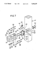
- FIG. 7 is a fragmentary perspective view of a metal connector and a jointing structure between a column and a beam using the metal connector showing a second preferred embodiment of the present invention
- FIG. 8 is a sectional view showing the jointing structure of FIG. 7 at a stage in assembling
- FIG. 9 is a perspective view of a metal connector and a jointing structure between a pair of beams in a series direction using the metal connector showing a third preferred embodiment of the present invention.
- FIG. 10 is a fragmentary perspective view of the metal connector and the jointing structure shown in FIG. 9;
- FIG. 11 is a perspective view of a metal connector showing a fourth preferred embodiment of the present invention.
- FIG. 12 is a side elevational view, partly in section, of a jointing structure between a column and a sill using the metal connector shown in FIG. 11;
- FIG. 13 is a side elevational view, partly in section, of a metal connector and a jointing structure between a column and a sill using the metal connector showing a fifth preferred embodiment of the present invention
- FIG. 14 is a fragmentary perspective view of the jointing structure shown in FIG. 13;
- FIG. 15 is a front elevational view of a metal connector and a jointing structure between top ends of a diagonal members which form a principal rafter using the metal connector showing a sixth preferred embodiment of the present invention
- FIG. 16 is a front elevational view showing a jointing structure in an arch-shaped building
- FIG. 17 is a front elevational view showing a jointing structure wherein a pair of left and right diagonal members are mounted between a central ridge member and left and right columns, respectively;
- FIG. 18 is a perspective view showing a conventional metal connector and a conventional jointing structure between and a column and a beam using the metal connector;
- FIG. 19 is a perspective view of the metal connector and the jointing structure of FIG. 18 but at a stage immediately before the column and the beam are finally secured to each other by means of wedge members.
- the metal connector shown includes a metal connector body 21 which includes a rectangular bottom plate 22, a rectangular core plate 23 secured uprightly to an upper face of the bottom plate 22 along a center line, and a mounting plate 24 placed securely and uprightly on an upper face of a longitudinal end portion of the bottom plate 22 and held in contact with and secured to an end face of the core plate 23.
- the bottom plate 22 extends, at a longitudinal outer end portion thereof, outwardly farther than the mounting plate 24 to form a lower flange 22'.
- the mounting plate 24 has a width equal to the width of the bottom plate 22 and has a height equal to the height of the core plate 23.
- the core plate 23 has a pair of rectangular window holes 25 perforated therein adjacent the mounting plate 24.
- the mounting plate 24 has a pair of bolt insertion holes 26 perforated therein in register with the window holes 25 of the core plate 23.
- a pair of threaded holes 27 are formed at upper and lower locations on an end face of the core plate 23 remote from the window holes 25, and a pair of fastening bolts 28 are screwed at base end portions thereof in the threaded holes 27.
- a nut or nuts 29 are screwed at the other end portion of each of the fastening bolts 28 together with a washer 29'.
- the core plate 23 has two threaded holes 30 formed in a predetermined spaced relationship on an upper end face thereof.
- the metal connector body 21 can be produced readily either by individually preparing the bottom plate 22, core plate 23 and mounting plate 24 and assembling them by suitable means such as welding or fastening screws or by molding or casting them as a unitary member.
- the metal connector is used to joint a column 31 and a beam 32 to each other.
- the column 31 has a recess 33 formed at a side face thereof at which it is to be jointed to the beam 32.
- the recess 33 has a sufficient size to receive therein the mounting plate 24 and the lower flange 22' of the bottom plate 22 on which the mounting plate 24 is mounted.
- the column 31 has two bolt insertion holes 34 perforated therein in an aligned relationship to the bolt insertion holes 26 of the mounting plate 24.
- the bolt insertion holes 34 extend from the bottom of the recess 33 to the opposite side face of the column 31.
- the metal connector body 21 is attached to the column 31 in the following manner.
- inner end portions of a pair of fastening bolts 35 are individually inserted into the bolt insertion holes 26 of the mounting plate 24 of the metal connector body 21, and then a pair of nuts 36 are individually fitted with and screwed onto the inner end portions of the fastening bolts 35 in the window holes 25 of the core plate 23.
- the fastening bolts 35 are inserted into the bolt insertion holes 34 of the column 31 until the mounting plate 24 and the lower flange 22' of the bottom plate 22 of the metal connector body 21 are received into the recess 33 of the column 31 and the other end threaded portions of the fastening bolts 35 are projected from the other side face of the column 31.
- a pair of fastening nuts 37 are screwed onto and tightened to the thus projected end threaded portions of the fastening bolts 35 to rigidly secure the metal connector body 21 horizontally to the column 31 as seen in FIG. 3.
- the beam 32 is jointed at a jointing end portion 38 thereof to the column 31 by means of the metal connector body 21.
- the jointing end portion 38 of the beam 32 has a fitting recess 39 formed therein which has a substantially same profile as that of the metal connector body 21 except the mounting plate 24 and the lower flange 22' of the bottom plate 22.
- the fitting recess 39 is thus composed of a horizontal flattened groove 40 formed in the jointing end portion 38 of the beam 32 and having a suitable size and shape to receive the bottom plate 22 of the metal connector body 21 therein, and a vertical slot 41 formed along the center line in the jointing end portion 38 perpendicularly and contiguously to the horizontal groove 40 and having a suitable size and shape to receive the core plate 23 of the metal connector body 21 therein.
- the horizontal groove 40 is opened to the bottom face and an outer end face of the jointing end portion 38 of the beam 32 while the vertical slot 41 is opened to the top face, bottom face and outer end face of the jointing end portion 38.
- a pair of upper and lower working window holes 42 are formed in the jointing end portion 38 of the beam 32.
- the working window holes 42 extend vertically, and the upper working window hole 42 is opened to the top face of the jointing end portion 38 of the beam 32 while the lower working window hole 42 is opened to the bottom face of the jointing end portion 38.
- a pair of bolt insertion holes 43 are formed in the jointing end portion 38 of the beam 32 to individually extend between the vertical slot 41 of the fitting recess 39 and the working window holes 42.
- the beam 32 is jointed to the column 31 in the following manner.
- the fastening bolts 28 are installed in position into the jointing end portion 38 of the beam 32. More particularly, the fastening bolts 28 are inserted into the bolt insertion holes 43 in the jointing end portion 38 of the beam 32 to a position in which base end portions thereof at least do not extend into the vertical groove 41 as seen from the upper fastening bolt 28 in FIG. 3.
- the jointing end portion 38 of the beam 32 is placed from above onto the metal connector body 21 mounted on the column 31 so that the metal connector body 21 is received into the fitting recess 39.
- the bottom plate 22 of the metal connector body 21 is fitted in the flattened groove 40 of the jointing end portion 38 of the beam 32 while the core plate 23 is fitted in the vertical slot 41, and the top face of the beam 32, that is, the top face of the jointing end portion 38, and the top face of the metal connector body 21, or more particularly the top face of the core plate 23, are aligned with each other.
- an operation of fitting the beam 32 with the metal connector body 21 does not require moving the beam 32 laterally in a horizontal direction, or in other words, even at a location where a spacing necessary for such lateral movement cannot be assured, such fitting operation can be performed readily by moving the jointing end portion 38 of the beam 32 downwardly from above, which is an advantage of a metal connector and a jointing structure according to the present invention.
- the fastening bolts 28 are operated to turn the fastening bolts 28 to move into the threaded holes 27 of the mounting plate 24, and then the washers 29' and the nuts 29 are fitted onto the base end portions of the fastening bolts 28 and the nuts 29 are turned to be tightened.
- the nuts 29 are used as a double nut or a dual nut in order to prevent possible loosening of the nuts 29.
- a pressing or fastening strength between the column 31 and the beam 32 can apparently be grasped quantitatively from an amount of movement of the nuts 29 on the fastening bolts 28, that is, an amount of turning motion of the nuts 29, which is another advantage of a metal connector and a jointing structure according to the present invention.
- a cover plate 44 is placed onto the top face of the jointing end portion 38 of the beam 32 jointed to the column 31 as seen in FIG. 1, and screws 46 are inserted into perforations 45 formed in the cover plate 44 and are screwed tightly into the threaded holes 30 at the top end of the core plate 23 as seen in FIG. 1.
- a packing plate 47 made of a same material as the beam 32 may additionally be inserted into each of the working window holes 42 of the beam 32 to fill up the working window holes 42.
- a column to beam jointing structure may otherwise joint two, three or four beams in different directions to a column.
- each beam can be jointed to a column using such metal connector as described above.
- attention must naturally be paid so that fastening bolts may not interfere with each other in the column.
- FIGS. 4 to 6 show three different modifications to the metal connector body 21 shown in FIGS. 1 to 3.
- the modified metal connector body shown in FIG. 4 is denoted also at 21 and constructed such that it has, in addition to the lower flange 22' which is an extension of the bottom plate 22, an upper flange 48 extending from the top end of an outer face of the mounting plate 24 in parallel to the lower flange 22'.
- a column 31 to which the modified metal connector body 21 is to be assembled has a pair of flange receiving grooves 49 and 50 formed at upper and lower ends of the recess 33 such that they may receive the upper and lower flanges 48 and 22' of the metal connector body 21, respectively.
- a cutaway portion 51 is provided at a corner of the mounting plate 24 to reduce the overall weight of the metal connector body 21.
- the modified metal connector body 21 shown in FIG. 5 is a modification also to the modified metal connector body 21 shown in FIG. 4 in that it has the upper flange 48 on the mounting plate 24 thereof but does not have the lower flange 22'.
- a column 31 for use with the present modified metal connector 21 may only have the upper flange receiving groove 49 at the top end of the recess 33.
- a cutaway portion 52 is provided at a vertical midpoint along the mounting plate 24 to reduce the overall weight of the metal connector body 21.
- the modified connector body 21 shown in FIG. 6 is constructed such that it does not have either of the upper and lower flanges 48 and 22'.
- a column 31 for use with the present modified metal connector 21 may have no flange receiving groove formed therein.
- a cutaway portion 53 is provided at a vertically mid portion of the mounting plate 24 to reduce the overall weight of the metal connector body 21.
- FIGS. 7 and 8 there are shown a metal connector and a jointing structure between a column and a beam using the metal connector according to a second preferred embodiment of the present invention.
- the metal connector and the jointing structure are a modification to the metal connector and the jointing structure shown in FIGS. 1 to 3, respectively, and since they have somewhat common construction, only differences of the former from the latter will be described below.
- the mounting plate 24 of the connector metal body 21 has two pairs of bolt head receiving tubes or hubs 54 formed in a predetermined spaced relationship on and extending outwardly from an outer face thereof. Meanwhile, the core plate 23 has a height a little smaller than the height of the mounting plate 24.
- a column 31 for use with the metal connector body 21 has two pairs of depressions 55 formed in a predetermined relationship on a side face thereof for receiving therein the bolt head receiving tubes 54 of the mounting plate 24 of the metal connector body 21.
- the depressions 55 are formed contiguously to and concentrically with the bolt insertion holes 34 formed in the column 31.
- a beam 32 for use with the metal connector body 21 has a shallow groove 56 formed on the top face of the jointing end portion 38 thereof for receiving the cover plate 44 therein. Further, the beam 32 has another shallow groove 57 formed on the outer longitudinal end of the jointing end portion 38 thereof for receiving the mounting plate 24 therein.
- the metal connector body 21 in the present embodiment is assembled to the column 31 in the following manner.
- the metal connector body 21 is operated to insert the bolt head receiving tubes 54 on the mounting plate 24 thereof into the depressions 55 of the column 31 until the mounting plate 24 is contacted with the opposing side face of the column 21.
- fastening bolts 58 are individually inserted into the bolt insertion holes 34 through round holes formed in the bolt head receiving tubes 54, and then nuts 59 are individually screwed tightly onto ends of the fastening bolts 58 which are projected outwardly from the opposite side face of the column 31, thereby to secure the metal connector body 21 to the column 32.
- the jointing end portion 38 of the beam 32 is fitted with the metal connector body 21 mounted on the column 31 in a similar manner as in the first embodiment described hereinabove. Consequently, the beam 32 is rigidly fastened to the column 31 by way of the metal connector body 21, thereby obtaining an intended jointing structure.
- cover plate 44 is fitted into and placed onto the bottom of the shallow groove 56 of the beam 32 and secured to the core plate 23 of the metal connector body 21 by means of the screws 46.
- the metal connector of the present embodiment includes a metal connector body 60 which includes a rectangular bottom plate 61 and a rectangular core plate 62 secured uprightly to an upper face of the bottom plate 61 along a center line.
- the core plate 62 has a pair of threaded holes 65 formed at upper and lower locations on each of the opposite longitudinal end faces thereof, and two pairs of bolts 63 and 64 are screwed at base end portions thereof in the threaded holes 65 of the core plate 62.
- a nut or nuts 66 are screwed at the other end portion of each of the fastening bolts 63 and 64 together with a washer 66'.
- Four threaded holes 67 are formed in a predetermined spaced relationship at an upper end face of the core plate 62.
- the metal connector body 60 can be produced readily either by individually preparing the bottom plate 61 and core plate 62 and assembling them by suitable means such as welding or fastening screws or by molding or casting them as a unitary member.
- the metal connector is used to joint a pair of beams 68 and 69 to each other along a straight line.
- the beams 68 and 69 are jointed at jointing end portions 70 and 71 thereof to each other by means of the metal connector body 60.
- the jointing end portions 70 and 71 of the beams 68 and 69 have a pair of fitting recesses 72 formed therein which generally have a substantially same profile as that of the metal connector body 60.
- Each of the fitting recesses 72 is thus composed of a flattened horizontal groove 73 formed at the bottom of the jointing end portion 70 or 71 of the beam 68 or 69 and having a suitable size and shape to receive a longitudinal half of the bottom plate 61 of the metal connector body 60 therein, and a vertical slot 74 formed along the center line in the jointing end portion 70 or 71 and having a suitable size and shape to receive a longitudinal half of the core plate 62 therein.
- the horizontal groove 73 is opened to the bottom face and an outer end face of the jointing end portion 70 or 71 of the beam 68 or 69 while the vertical slot 74 is opened to the top face, bottom face and outer end face of the jointing end portion 70 or 71.
- a pair of upper and lower working window holes 75 are formed in each of the jointing end portions 70 and 71 of the beams 68 and 69.
- the upper working window hole 75 is opened to the top face of the jointing end portion 70 or 71 while the lower working window hole 75 is opened to the bottom face of the jointing end portion 70 or 71.
- Each of the jointing end portions 70 and 71 of the beams 68 and 69 has a pair of bolt insertion holes 76 formed therein such that they individually extend between the vertical slop 74 of the fitting recess 72 and the working window holes 75.
- the beams 68 and 69 are jointed to each other in the following manner.
- the fastening bolts 63 and 64 are installed in position into the jointing end portion 70 and 71 of the beams 68 and 69, respectively. More particularly, the fastening bolts 63 and 64 are inserted into the bolt insertion holes 76 in the jointing end portions 70 and 71 of the beams 68 and 69 to a position in which base end portions thereof at least do not extend into the vertical slots 74.
- the jointing end portions 70 and 71 of the beams 68 and 69 are placed from above onto the metal connector body 60 so that the metal connector body 60 is received into the fitting recesses 72 of the jointing end portions 70 and 71 while the jointing end portions 70 and 71 are placed onto the bottom plate 61 of the metal connector body 60.
- base end portions of the fastening bolts 63 and 64 are operated to turn the fastening bolts 63 and 64 to move into the threaded holes 65 of the core plate 62, and then the washers 66' and the nuts 66 are fitted onto the base end portions of the fastening bolts 63 and 64 and the nuts 66 are turned to be tightened.
- the nuts 66 are used as a double nut or a dual nut in order to prevent possible loosening of the nuts 66.
- a cover plate 77 is placed onto the top faces of the jointing end portions 70 and 71 of the beams 68 and 69, and screws 79 are inserted into perforations 78 formed in the cover plate 77 and are screwed tightly into the threaded holes 67 at the top end of the core plate 62 as seen in FIG. 9.
- a packing plate 80 made of a same material as the beams 68 and 69 may additionally be inserted into each of the working window holes 75 of the beams 68 and 69 to fill up the working window holes 75.
- the metal connector shown includes a metal connector body 83 which includes a rectangular bottom plate 84, a core plate 85 mounted uprightly on an upper face of the bottom plate 84 along a center line, and a pair of mounting plates 86 mounted on the bottom plate 84 adjacent the opposite longitudinal ends of the core plate 85 and having a greater height than the core plate 85.
- the bottom plate 84 extends at the opposite longitudinal ends thereof outwardly farther than the mounting plates 86 to form a pair of lower flanges 87.
- a pair of bolt insertion holes 88 are performed in each of the lower flanges 87 of the bottom plate 84.
- a pair of threaded holes 89 are formed on the top face of the core plate 85, and a pair of fastening bolts 90 are screwed at bottom end portions thereof in the threaded holes 89 of the core plate 85.
- the metal connector body 83 is secured, at the bottom plate 84 thereof, to an upper face of a sill 82 by means of a plurality of fastening bolts 91 and nuts 91'.
- a column 81 to be jointed to the sill 82 by means of the metal connector has a fitting recess formed at a joining end portion 92, that is, a lower end portion thereof for receiving the metal connector body 83 in a similar manner as the fitting recess 39 of the beam 32 in the first embodiment described hereinabove.
- the metal connector body 83 is fitted in the fitting recess of the column 81, and a lower end face of the jointing end portion 92 of the column 81 is held in contact with the top face of the bottom plate 84 on the sill 82.
- a packing plate 93 similar to the packing plate 47 in the first embodiment is filled in each of a pair of working window holes 94 formed in the jointing end portion 92 of the column 81.
- a nut 90' is screwed to an end portion of each of the fastening bolts 90 extending into the corresponding working window hole 94.
- the metal connector shown includes a metal connector body 97 which includes a square bottom plate 98, and a core plate 99 mounted uprightly on an upper face of the square bottom plate 99 and having a cross shape in plan.
- Four bolts 100 are screwed vertically at base end portions thereof in threaded holes 99' formed at the top face of the cross-shaped core plate 99 while a pair of fastening bolts 101 are screwed horizontally at base end portions thereof in threaded holes formed in each of four outer end faces of the cross-shaped core plate 99 as seen in FIG. 14.
- the metal connector body 97 is secured, at the bottom plate 98 thereof, to an upper face of a sill 96 by means of four anchor bolts 102 and four nuts 102'.
- a column 95 to be jointed to the sill 96 by means of the metal connector has a fitting recess 105 formed at a joining end portion 103, that is, a lower end portion thereof and composed of a pair of vertical slots 104 which are opened to the four side faces of the jointing end portion 103 and cross each other in such a manner as to provide the fitting recess 105 with a cross shape in plan which conforms to the cross shape of the core plate 99 of the metal connector body 97.
- the column 95 further has four working window holes 106 formed therein in a spaced relationship above the vertical slots 104, and four bolt insertion holes 107 are formed between the working window holes 106 and the vertical slots 104.
- the column 95 is assembled to the sill 96 in the following manner by way of the metal connector body 97.
- the column 95 is operated so that the cross-shaped core plate 99 of the metal connector body 97 mounted on the sill 96 is fitted into the fitting recess 105 of the column 95 while upper end portions of the fastening bolts 100 on the core plate 99 are individually inserted into the bolt insertion holes 107 of the jointing end portion 103 of the column 95 until they are projected into the working window holes 106 of the column 95.
- nuts 108 are screwed to and tightened on the end portions of the fastening bolts 100 projected into the working window holes 106 thereby to fasten the jointing end portion 103 of the column 95 to the sill 96 with the bottom plate 98 of the metal connector body 97 interposed therebetween.
- a packing plate 109 similar to the packing plate 47 in the first embodiment may be filled in each of the working window holes 106.
- a cover plate 109' similar to the cover plate 44 in the first embodiment is secured to each of the four side faces of the jointing end portion 103 of the column 92 by screwing nuts 109" to end portions of the fastening bolts 101 projected from the four side faces of the column 95.
- FIG. 15 there are shown a metal connector and a jointing structure between a pair of diagonal members using the metal connector according to a sixth embodiment of the present invention. More particularly, the metal connector is used to joint top portions of a pair of left and right diagonal members 110 and 111 which form a principal rafter.
- the jointing structure is similar in a sense to the jointing structure between a pair of the beams in a serial direction using the metal connector of the third embodiment shown in FIGS. 9 and 10.
- the jointing structure of the present embodiment is only different from the jointing structure in the third embodiment in that a bottom plate 61 and a core plate 62 of a metal connector body 114 of the metal connector of the present embodiment each having a comparatively great length are bent in an inverted V-shape at an angle at which the left and right diagonal members 110 and 111 are to be jointed to each other at jointing end portions 112 and 113 thereof.
- a cover plate 115 is also bent in an inverted V-shape at the same angle as the metal connector body 114.
- the arch-shaped building 116 employs, at a curved jointing portion thereof, a modification to the metal connector body 60 in the third embodiment described above, and employs, at a jointing portion between a column thereof and a sill, the metal connector body 83 in the fourth embodiment described above.
- a modified metal connector body 120 and a pair of modified metal connector bodies 121 are employed for a top portion 117 and a pair of left and right curved portions 118 and 119, respectively, of the arch-shaped building 116.
- the metal connector bodies 120 and 121 are modifications to the metal connector body 60 in the third embodiment in that the bottom plate 61 and core plate 62 are curved with a curvature conforming to the curvature of the corresponding portion of the arch-shaped building.
- the metal connector body 83 in the fourth embodiment is employed to secure each of a pair of left and right columns 122 of the arch-shaped building 116 to a sill 123.
- FIG. 17 shows a jointing structure in a building 127 wherein a pair of left and right diagonal members 126 extend between a central ridge member 124 and a pair of left and right columns 125.
- a metal connector body 128 which is a modification to the metal connector body 21 in the first embodiment that is different from the modifications shown in FIGS. 4 to 6 is employed for jointing between the ridge member 124 of the building 127 and a top portion of each of the left and right diagonal members 126
- another metal connector body 129 which is another different modification to the metal connector body 21 in the first embodiment is employed for jointing between a lower end portion of each of the left and right diagonal members 126 and a top portion of a corresponding one of the left and right columns 125.
- the metal connector body 128 is constructed such that the mounting plate 24 is mounted in an inclined relationship at an obtuse angle with respect to the bottom plate 22.
- the metal connector body 129 is constructed such that the mounting plate 24 is mounted in an inclined relationship at an acute angle with respect to the bottom plate 22.
- the metal connector bodies 128 and 129 are thus shaped so as to have angles conforming to angles made by the jointing portions of the building 127.
- the metal connector body 83 is employed to secure each of the left and right columns 125 to a sill 130.
Landscapes
- Engineering & Computer Science (AREA)
- Architecture (AREA)
- Physics & Mathematics (AREA)
- Electromagnetism (AREA)
- Civil Engineering (AREA)
- Structural Engineering (AREA)
- Joining Of Building Structures In Genera (AREA)
Applications Claiming Priority (2)
| Application Number | Priority Date | Filing Date | Title |
|---|---|---|---|
| JP3-039254[U] | 1991-03-11 | ||
| JP1991039254U JPH0754405Y2 (ja) | 1991-03-11 | 1991-03-11 | 木造建築材用締結金具と木造建築物の締結構造 |
Publications (1)
| Publication Number | Publication Date |
|---|---|
| US5242239A true US5242239A (en) | 1993-09-07 |
Family
ID=12548008
Family Applications (1)
| Application Number | Title | Priority Date | Filing Date |
|---|---|---|---|
| US07/815,141 Expired - Fee Related US5242239A (en) | 1991-03-11 | 1991-12-31 | Metal connector for building and jointing structure of building using the same |
Country Status (2)
| Country | Link |
|---|---|
| US (1) | US5242239A (ja) |
| JP (1) | JPH0754405Y2 (ja) |
Cited By (48)
| Publication number | Priority date | Publication date | Assignee | Title |
|---|---|---|---|---|
| US5363625A (en) * | 1991-08-06 | 1994-11-15 | Gerd Philippi | Modular building system |
| US5438811A (en) * | 1993-03-22 | 1995-08-08 | Shigeo Goya | Jointing metal fixture for construction |
| US5577856A (en) * | 1993-08-10 | 1996-11-26 | Tezuka; Junichi | Beam support system for forming precompressed wood joints |
| US5620275A (en) * | 1994-12-23 | 1997-04-15 | Novacek; Josef | Timber beam hanger and resulting beam connection |
| US5636934A (en) * | 1994-06-21 | 1997-06-10 | Kyoto Mokuzou Kenchiku Kenkyuusho | Structural connector, and method of making structural joint |
| WO1998031512A1 (en) * | 1997-01-22 | 1998-07-23 | Icf Kaiser Engineers, Inc. | Bolted connector for connecting beams to columns |
| US5881509A (en) * | 1995-11-23 | 1999-03-16 | Inafuku Construction Co., Ltd. | Spiral staircase and connecting metals for spiral staircase |
| US5896721A (en) * | 1996-11-19 | 1999-04-27 | West Company Limited | Metal device for joining wooden members in wooden building |
| US5921049A (en) * | 1996-11-20 | 1999-07-13 | West Company Limited | Device for forming framework of wooden building |
| US5941044A (en) * | 1997-08-06 | 1999-08-24 | Sera; Yousuke | Connection structure between a column and cross beams of timber construction and a connection method for connecting the column and cross beams |
| US6032431A (en) * | 1996-11-15 | 2000-03-07 | West Company Limited | Device for forming framework of wooden building |
| US6367224B1 (en) | 2000-02-07 | 2002-04-09 | Simpson Strong-Tie Co., Inc. | Hidden connector |
| US6427391B1 (en) | 1999-10-22 | 2002-08-06 | Martin G. Lyons | Methods and apparatus for attaching a cantilevered beam to a building |
| US6474902B1 (en) | 1997-01-22 | 2002-11-05 | Icf Kaiser Engineers, Inc. | Connector for connecting beams to columns |
| US20070175158A1 (en) * | 2006-01-04 | 2007-08-02 | Cope Ted E | Timber end-joint |
| US20110179725A1 (en) * | 2006-12-22 | 2011-07-28 | Badri Hiriyur | Moment frame connector |
| US20110318095A1 (en) * | 2010-06-23 | 2011-12-29 | Jocelyn Beaulieu | Furniture connector and furniture utilizing same |
| EP2022903A3 (de) * | 2007-06-26 | 2012-03-28 | GEZE GmbH | Befestigungsanordnung und Montageverfahren zum Einbau einer Trägerplatte in eine Durchgangsöffnung zwischen Wänden |
| US20120317919A1 (en) * | 2009-11-06 | 2012-12-20 | Housh Rahimzadeh | Building Structures and Construction Methods |
| US20140013701A1 (en) * | 2012-07-14 | 2014-01-16 | Richard Bradley Rodgers | Bracket for use in building construction |
| US8800232B1 (en) * | 2011-04-04 | 2014-08-12 | LEK Innovations, LLC | Flange shear connection for precast concrete structures |
| US9056235B1 (en) * | 2012-02-22 | 2015-06-16 | David Mortland | Punching bag gantry assembly |
| US9068365B2 (en) * | 2010-10-28 | 2015-06-30 | Sika Technology Ag | Anchoring the ends of tension members on reinforced concrete beams |
| US9145672B1 (en) * | 2014-08-11 | 2015-09-29 | Lance Broughton | Apparatus and method for attaching deck to structure |
| US9145669B1 (en) * | 2014-05-05 | 2015-09-29 | Lance Broughton | Apparatus and method for attaching deck to structure |
| CN105220809A (zh) * | 2015-10-26 | 2016-01-06 | 济南轨道交通集团有限公司 | 一种拱形顶板与牛腿桩的连接结构及其施工方法 |
| EP2989928A1 (de) * | 2014-08-27 | 2016-03-02 | Grass GmbH | Vorrichtung zur befestigung einer seitenabdeckung an einem blendenprofil eines bewegbaren möbelteils |
| CN105710676A (zh) * | 2016-04-14 | 2016-06-29 | 燕山大学 | 一种柔性夹具 |
| US20160289949A1 (en) * | 2013-11-06 | 2016-10-06 | Kenho Okura | Connecting structure |
| RU2633897C1 (ru) * | 2016-10-12 | 2017-10-19 | Федеральное государственное бюджетное образовательное учреждение высшего образования "Оренбургский государственный университет" | Узловое сборно-разборное соединение деревянных стержней |
| US9920531B1 (en) * | 2015-03-09 | 2018-03-20 | Connecticut Post & Beam LLC | Post and beam system |
| US9949563B2 (en) | 2012-06-16 | 2018-04-24 | Stact Wine Displays Inc. | Bottle rack and kit for bottle-supporting assembly |
| US10004330B1 (en) * | 2016-12-23 | 2018-06-26 | Stact Wine Displays Inc. | Bottle rack |
| USD821831S1 (en) | 2015-03-24 | 2018-07-03 | Stact Wine Displays Inc. | Bottle rack |
| USD834900S1 (en) | 2017-01-04 | 2018-12-04 | Stact Wine Displays Inc. | Bottle rack |
| WO2019006447A1 (en) * | 2017-06-30 | 2019-01-03 | Patco, Llc | BALCONY INSTALLATION |
| USD848802S1 (en) | 2017-01-04 | 2019-05-21 | Stact Wine Displays Inc. | Bottle rack |
| JP2020007797A (ja) * | 2018-07-09 | 2020-01-16 | 三井住友建設株式会社 | 柱と木造梁との接合構造 |
| USD878828S1 (en) | 2017-11-13 | 2020-03-24 | Stact Wine Displays Inc. | Bottle rack |
| RU198878U1 (ru) * | 2020-04-17 | 2020-07-30 | Павел Сергеевич Булыгин | Узел соединения протяженных деревянных элементов |
| USD923987S1 (en) | 2017-11-13 | 2021-07-06 | Stact Wine Displays Inc. | Bottle racks |
| US11299880B2 (en) | 2006-12-22 | 2022-04-12 | Simpson Strong-Tie Company Inc. | Moment frame connector |
| US20220307255A1 (en) * | 2020-06-23 | 2022-09-29 | Sekisui House, Ltd. | Joint metal and building structure |
| EP4108879A1 (de) * | 2021-06-23 | 2022-12-28 | Bartels Systembeschläge GmbH | Blendenhalterung zur festlegung einer blende an einer tür- oder fensterzarge |
| US20230257988A1 (en) * | 2020-07-30 | 2023-08-17 | Sekisui House, Ltd. | Diagonal beam joining hardware and beam connecting structure |
| US20230332395A1 (en) * | 2022-04-18 | 2023-10-19 | Simpson Strong-Tie Company Inc. | Heavy Seat Knife Plate Hanger |
| WO2024039346A1 (en) * | 2022-08-17 | 2024-02-22 | Tekirdag Namik Kemal Universitesi | Replaceable joint detail that does not require short cantilever for moment transferring beam-column connections in precast reinforced concrete structures |
| USD1092161S1 (en) | 2023-09-22 | 2025-09-09 | Stact Wine Displays Inc. | Bottle rack |
Families Citing this family (1)
| Publication number | Priority date | Publication date | Assignee | Title |
|---|---|---|---|---|
| CN108547379A (zh) * | 2018-04-17 | 2018-09-18 | 西京学院 | 一种装配式钢木结构连接节点 |
Citations (16)
| Publication number | Priority date | Publication date | Assignee | Title |
|---|---|---|---|---|
| NL291911A (ja) * | 1962-04-25 | |||
| US1335554A (en) * | 1917-06-27 | 1920-03-30 | Thomas J Callahan | Sill-joint for cut-to-fit greenhouses |
| US1657243A (en) * | 1924-12-06 | 1928-01-24 | Daniels Ernest Stuart | Joist and rafter suspension bracket |
| US1775572A (en) * | 1927-12-09 | 1930-09-09 | William L Ross | Steel framework construction |
| DE658283C (de) * | 1935-08-30 | 1938-03-28 | Wilhelm Knapp G M B H Maschf | Strebenverbindung fuer den eisernen Grubenausbau |
| US3064321A (en) * | 1957-10-14 | 1962-11-20 | Homer C Rose | Fastenings |
| FR1423034A (fr) * | 1964-11-18 | 1966-01-03 | Assemblage démontable d'éléments profilés cruciformes permettant la constitution sans perforation d'armatures destinées à tous usages | |
| CH422652A (de) * | 1964-10-08 | 1966-10-15 | Glatt Werner | Einrichtung zur Behandlung von körnigem oder feinstückigem Gut in einem Luftstrom |
| US4040694A (en) * | 1974-12-12 | 1977-08-09 | La Telemecanique Electrique | Framework for metal cabinet |
| DE3401303A1 (de) * | 1984-01-16 | 1985-07-25 | Forster, Jan, Dipl.-Ing., 8000 München | Verbindungsmittel und verbindung fuer holzbauteile |
| US4558968A (en) * | 1980-12-12 | 1985-12-17 | Streif Ag | Beam connector |
| US4616950A (en) * | 1984-01-31 | 1986-10-14 | Morris Tom C | Timber joining devices |
| JPH0235142A (ja) * | 1988-07-26 | 1990-02-05 | Shokusan Jutaku Sogo Co Ltd | 建物の構造用金物 |
| JPH02157338A (ja) * | 1988-12-09 | 1990-06-18 | Shokusan Jutaku Sogo Co Ltd | 建物の構造用金物 |
| US4981388A (en) * | 1989-04-17 | 1991-01-01 | Green-Mountain Precision Frames, Inc. | Timber joining system |
| US5061111A (en) * | 1991-01-02 | 1991-10-29 | Kiyoshi Hosokawa | Metal connector for wooden building and jointing structure of wooden building using the same |
-
1991
- 1991-03-11 JP JP1991039254U patent/JPH0754405Y2/ja not_active Expired - Fee Related
- 1991-12-31 US US07/815,141 patent/US5242239A/en not_active Expired - Fee Related
Patent Citations (16)
| Publication number | Priority date | Publication date | Assignee | Title |
|---|---|---|---|---|
| US1335554A (en) * | 1917-06-27 | 1920-03-30 | Thomas J Callahan | Sill-joint for cut-to-fit greenhouses |
| US1657243A (en) * | 1924-12-06 | 1928-01-24 | Daniels Ernest Stuart | Joist and rafter suspension bracket |
| US1775572A (en) * | 1927-12-09 | 1930-09-09 | William L Ross | Steel framework construction |
| DE658283C (de) * | 1935-08-30 | 1938-03-28 | Wilhelm Knapp G M B H Maschf | Strebenverbindung fuer den eisernen Grubenausbau |
| US3064321A (en) * | 1957-10-14 | 1962-11-20 | Homer C Rose | Fastenings |
| NL291911A (ja) * | 1962-04-25 | |||
| CH422652A (de) * | 1964-10-08 | 1966-10-15 | Glatt Werner | Einrichtung zur Behandlung von körnigem oder feinstückigem Gut in einem Luftstrom |
| FR1423034A (fr) * | 1964-11-18 | 1966-01-03 | Assemblage démontable d'éléments profilés cruciformes permettant la constitution sans perforation d'armatures destinées à tous usages | |
| US4040694A (en) * | 1974-12-12 | 1977-08-09 | La Telemecanique Electrique | Framework for metal cabinet |
| US4558968A (en) * | 1980-12-12 | 1985-12-17 | Streif Ag | Beam connector |
| DE3401303A1 (de) * | 1984-01-16 | 1985-07-25 | Forster, Jan, Dipl.-Ing., 8000 München | Verbindungsmittel und verbindung fuer holzbauteile |
| US4616950A (en) * | 1984-01-31 | 1986-10-14 | Morris Tom C | Timber joining devices |
| JPH0235142A (ja) * | 1988-07-26 | 1990-02-05 | Shokusan Jutaku Sogo Co Ltd | 建物の構造用金物 |
| JPH02157338A (ja) * | 1988-12-09 | 1990-06-18 | Shokusan Jutaku Sogo Co Ltd | 建物の構造用金物 |
| US4981388A (en) * | 1989-04-17 | 1991-01-01 | Green-Mountain Precision Frames, Inc. | Timber joining system |
| US5061111A (en) * | 1991-01-02 | 1991-10-29 | Kiyoshi Hosokawa | Metal connector for wooden building and jointing structure of wooden building using the same |
Cited By (65)
| Publication number | Priority date | Publication date | Assignee | Title |
|---|---|---|---|---|
| US5363625A (en) * | 1991-08-06 | 1994-11-15 | Gerd Philippi | Modular building system |
| US5438811A (en) * | 1993-03-22 | 1995-08-08 | Shigeo Goya | Jointing metal fixture for construction |
| US5577856A (en) * | 1993-08-10 | 1996-11-26 | Tezuka; Junichi | Beam support system for forming precompressed wood joints |
| US5636934A (en) * | 1994-06-21 | 1997-06-10 | Kyoto Mokuzou Kenchiku Kenkyuusho | Structural connector, and method of making structural joint |
| US5938366A (en) * | 1994-12-23 | 1999-08-17 | Novacek; Josef | Timber beam hanger and resulting beam connection |
| US5620275A (en) * | 1994-12-23 | 1997-04-15 | Novacek; Josef | Timber beam hanger and resulting beam connection |
| US5881509A (en) * | 1995-11-23 | 1999-03-16 | Inafuku Construction Co., Ltd. | Spiral staircase and connecting metals for spiral staircase |
| US6032431A (en) * | 1996-11-15 | 2000-03-07 | West Company Limited | Device for forming framework of wooden building |
| US5896721A (en) * | 1996-11-19 | 1999-04-27 | West Company Limited | Metal device for joining wooden members in wooden building |
| US5921049A (en) * | 1996-11-20 | 1999-07-13 | West Company Limited | Device for forming framework of wooden building |
| WO1998031512A1 (en) * | 1997-01-22 | 1998-07-23 | Icf Kaiser Engineers, Inc. | Bolted connector for connecting beams to columns |
| US6059482A (en) * | 1997-01-22 | 2000-05-09 | Icf Kaiser Engineering, Inc. | Bolted connector for connecting beams to columns |
| US6474902B1 (en) | 1997-01-22 | 2002-11-05 | Icf Kaiser Engineers, Inc. | Connector for connecting beams to columns |
| US5941044A (en) * | 1997-08-06 | 1999-08-24 | Sera; Yousuke | Connection structure between a column and cross beams of timber construction and a connection method for connecting the column and cross beams |
| US6427391B1 (en) | 1999-10-22 | 2002-08-06 | Martin G. Lyons | Methods and apparatus for attaching a cantilevered beam to a building |
| US6367224B1 (en) | 2000-02-07 | 2002-04-09 | Simpson Strong-Tie Co., Inc. | Hidden connector |
| US20070175158A1 (en) * | 2006-01-04 | 2007-08-02 | Cope Ted E | Timber end-joint |
| US11299880B2 (en) | 2006-12-22 | 2022-04-12 | Simpson Strong-Tie Company Inc. | Moment frame connector |
| US8375652B2 (en) * | 2006-12-22 | 2013-02-19 | Simpson Strong-Tie Company, Inc. | Moment frame connector |
| US20110179725A1 (en) * | 2006-12-22 | 2011-07-28 | Badri Hiriyur | Moment frame connector |
| EP2022903A3 (de) * | 2007-06-26 | 2012-03-28 | GEZE GmbH | Befestigungsanordnung und Montageverfahren zum Einbau einer Trägerplatte in eine Durchgangsöffnung zwischen Wänden |
| US20120317919A1 (en) * | 2009-11-06 | 2012-12-20 | Housh Rahimzadeh | Building Structures and Construction Methods |
| US8898992B2 (en) * | 2009-11-06 | 2014-12-02 | Diversakore Holdings, Llc | Building structures and construction methods |
| US20110318095A1 (en) * | 2010-06-23 | 2011-12-29 | Jocelyn Beaulieu | Furniture connector and furniture utilizing same |
| US9068365B2 (en) * | 2010-10-28 | 2015-06-30 | Sika Technology Ag | Anchoring the ends of tension members on reinforced concrete beams |
| US8800232B1 (en) * | 2011-04-04 | 2014-08-12 | LEK Innovations, LLC | Flange shear connection for precast concrete structures |
| US9056235B1 (en) * | 2012-02-22 | 2015-06-16 | David Mortland | Punching bag gantry assembly |
| US10441075B2 (en) | 2012-06-16 | 2019-10-15 | Stact Wine Displays Inc. | Bottle rack and kit for bottle-supporting assembly |
| US9949563B2 (en) | 2012-06-16 | 2018-04-24 | Stact Wine Displays Inc. | Bottle rack and kit for bottle-supporting assembly |
| US8898993B2 (en) * | 2012-07-14 | 2014-12-02 | Richard Bradley Rodgers | Bracket for use in building construction |
| US20140013701A1 (en) * | 2012-07-14 | 2014-01-16 | Richard Bradley Rodgers | Bracket for use in building construction |
| US20160289949A1 (en) * | 2013-11-06 | 2016-10-06 | Kenho Okura | Connecting structure |
| US9145669B1 (en) * | 2014-05-05 | 2015-09-29 | Lance Broughton | Apparatus and method for attaching deck to structure |
| US9145672B1 (en) * | 2014-08-11 | 2015-09-29 | Lance Broughton | Apparatus and method for attaching deck to structure |
| EP2989928A1 (de) * | 2014-08-27 | 2016-03-02 | Grass GmbH | Vorrichtung zur befestigung einer seitenabdeckung an einem blendenprofil eines bewegbaren möbelteils |
| US9920531B1 (en) * | 2015-03-09 | 2018-03-20 | Connecticut Post & Beam LLC | Post and beam system |
| USD891202S1 (en) | 2015-03-24 | 2020-07-28 | Stact Wine Displays Inc. | Bottle rack |
| USD821831S1 (en) | 2015-03-24 | 2018-07-03 | Stact Wine Displays Inc. | Bottle rack |
| CN105220809A (zh) * | 2015-10-26 | 2016-01-06 | 济南轨道交通集团有限公司 | 一种拱形顶板与牛腿桩的连接结构及其施工方法 |
| CN105710676B (zh) * | 2016-04-14 | 2017-12-29 | 燕山大学 | 一种柔性夹具 |
| CN105710676A (zh) * | 2016-04-14 | 2016-06-29 | 燕山大学 | 一种柔性夹具 |
| RU2633897C1 (ru) * | 2016-10-12 | 2017-10-19 | Федеральное государственное бюджетное образовательное учреждение высшего образования "Оренбургский государственный университет" | Узловое сборно-разборное соединение деревянных стержней |
| US10004330B1 (en) * | 2016-12-23 | 2018-06-26 | Stact Wine Displays Inc. | Bottle rack |
| US11382424B2 (en) | 2016-12-23 | 2022-07-12 | Stact Wine Displays Inc. | Bottle rack |
| US10835037B2 (en) | 2016-12-23 | 2020-11-17 | Stact Wine Displays Inc. | Bottle rack |
| USD848802S1 (en) | 2017-01-04 | 2019-05-21 | Stact Wine Displays Inc. | Bottle rack |
| USD834900S1 (en) | 2017-01-04 | 2018-12-04 | Stact Wine Displays Inc. | Bottle rack |
| US10851536B2 (en) | 2017-06-30 | 2020-12-01 | Patco, Llc | Balcony installation |
| US11585080B2 (en) | 2017-06-30 | 2023-02-21 | Patco, Llc | Balcony installation |
| WO2019006447A1 (en) * | 2017-06-30 | 2019-01-03 | Patco, Llc | BALCONY INSTALLATION |
| CN111356810A (zh) * | 2017-06-30 | 2020-06-30 | 帕特克有限公司 | 阳台安装 |
| CN111356810B (zh) * | 2017-06-30 | 2022-03-25 | 帕特克有限公司 | 阳台安装 |
| USD994404S1 (en) | 2017-11-13 | 2023-08-08 | Stact Wine Displays Inc. | Bottle racks |
| USD878828S1 (en) | 2017-11-13 | 2020-03-24 | Stact Wine Displays Inc. | Bottle rack |
| USD923987S1 (en) | 2017-11-13 | 2021-07-06 | Stact Wine Displays Inc. | Bottle racks |
| USD1027580S1 (en) | 2017-11-13 | 2024-05-21 | Stact Wine Displays Inc. | Bottle racks |
| JP2020007797A (ja) * | 2018-07-09 | 2020-01-16 | 三井住友建設株式会社 | 柱と木造梁との接合構造 |
| RU198878U1 (ru) * | 2020-04-17 | 2020-07-30 | Павел Сергеевич Булыгин | Узел соединения протяженных деревянных элементов |
| US20220307255A1 (en) * | 2020-06-23 | 2022-09-29 | Sekisui House, Ltd. | Joint metal and building structure |
| US20230257988A1 (en) * | 2020-07-30 | 2023-08-17 | Sekisui House, Ltd. | Diagonal beam joining hardware and beam connecting structure |
| US12565770B2 (en) * | 2020-07-30 | 2026-03-03 | Sekisui House, Ltd. | Diagonal beam joining hardware and beam connecting structure |
| EP4108879A1 (de) * | 2021-06-23 | 2022-12-28 | Bartels Systembeschläge GmbH | Blendenhalterung zur festlegung einer blende an einer tür- oder fensterzarge |
| US20230332395A1 (en) * | 2022-04-18 | 2023-10-19 | Simpson Strong-Tie Company Inc. | Heavy Seat Knife Plate Hanger |
| WO2024039346A1 (en) * | 2022-08-17 | 2024-02-22 | Tekirdag Namik Kemal Universitesi | Replaceable joint detail that does not require short cantilever for moment transferring beam-column connections in precast reinforced concrete structures |
| USD1092161S1 (en) | 2023-09-22 | 2025-09-09 | Stact Wine Displays Inc. | Bottle rack |
Also Published As
| Publication number | Publication date |
|---|---|
| JPH0754405Y2 (ja) | 1995-12-18 |
| JPH0545103U (ja) | 1993-06-18 |
Similar Documents
| Publication | Publication Date | Title |
|---|---|---|
| US5242239A (en) | Metal connector for building and jointing structure of building using the same | |
| US5253945A (en) | Metal connector for building and jointing structure of building using the same | |
| US5061111A (en) | Metal connector for wooden building and jointing structure of wooden building using the same | |
| CA1115926A (en) | Beam connector | |
| CA1273812A (en) | Apertured channel veneer anchor | |
| US6532713B2 (en) | Joint structure for joining composite beam and column | |
| US5375389A (en) | Joint apparatus for construction members | |
| JP3250972B2 (ja) | 柱梁等接合金物及び柱梁等の接合方法 | |
| JP2801854B2 (ja) | 建築用ネジ締め装置 | |
| JP2807524B2 (ja) | 柱と梁の接合構造 | |
| JPH07207765A (ja) | 建築用ネジ締め装置 | |
| JPH0728251Y2 (ja) | 木構造における集成材梁の接合部構造 | |
| JPH0439922Y2 (ja) | ||
| JPH08199848A (ja) | 柱の補強装置 | |
| JP3031391U (ja) | 建築用接合金具とそれを使用した建築物の接合構造 | |
| JPH0634971Y2 (ja) | 木造建築物における柱・梁接合構造 | |
| JPS6316766Y2 (ja) | ||
| JP3004111U (ja) | 建築用ネジ締め装置 | |
| JP2681622B2 (ja) | 木造建築物における柱・横架材接合構造 | |
| JPH04357229A (ja) | 木質構造部材の接合金具および接合部構造 | |
| JPS6124588Y2 (ja) | ||
| JPH0217047Y2 (ja) | ||
| JPH0124265Y2 (ja) | ||
| JP2857374B2 (ja) | 架構材接合構造 | |
| JPH0629287Y2 (ja) | 部材の連結構造 |
Legal Events
| Date | Code | Title | Description |
|---|---|---|---|
| FEPP | Fee payment procedure |
Free format text: PAYOR NUMBER ASSIGNED (ORIGINAL EVENT CODE: ASPN); ENTITY STATUS OF PATENT OWNER: SMALL ENTITY |
|
| FPAY | Fee payment |
Year of fee payment: 4 |
|
| FPAY | Fee payment |
Year of fee payment: 8 |
|
| REMI | Maintenance fee reminder mailed | ||
| LAPS | Lapse for failure to pay maintenance fees | ||
| STCH | Information on status: patent discontinuation |
Free format text: PATENT EXPIRED DUE TO NONPAYMENT OF MAINTENANCE FEES UNDER 37 CFR 1.362 |
|
| FP | Lapsed due to failure to pay maintenance fee |
Effective date: 20050907 |