US5211167A - Ultrasonic diagnosing apparatus - Google Patents
Ultrasonic diagnosing apparatus Download PDFInfo
- Publication number
- US5211167A US5211167A US07/838,920 US83892092A US5211167A US 5211167 A US5211167 A US 5211167A US 83892092 A US83892092 A US 83892092A US 5211167 A US5211167 A US 5211167A
- Authority
- US
- United States
- Prior art keywords
- mark
- organ
- ultrasonic
- posture
- marks
- Prior art date
- Legal status (The legal status is an assumption and is not a legal conclusion. Google has not performed a legal analysis and makes no representation as to the accuracy of the status listed.)
- Expired - Lifetime
Links
Images


Classifications
-
- G—PHYSICS
- G01—MEASURING; TESTING
- G01S—RADIO DIRECTION-FINDING; RADIO NAVIGATION; DETERMINING DISTANCE OR VELOCITY BY USE OF RADIO WAVES; LOCATING OR PRESENCE-DETECTING BY USE OF THE REFLECTION OR RERADIATION OF RADIO WAVES; ANALOGOUS ARRANGEMENTS USING OTHER WAVES
- G01S7/00—Details of systems according to groups G01S13/00, G01S15/00, G01S17/00
- G01S7/52—Details of systems according to groups G01S13/00, G01S15/00, G01S17/00 of systems according to group G01S15/00
- G01S7/52017—Details of systems according to groups G01S13/00, G01S15/00, G01S17/00 of systems according to group G01S15/00 particularly adapted to short-range imaging
- G01S7/52053—Display arrangements
- G01S7/52057—Cathode ray tube displays
- G01S7/52073—Production of cursor lines, markers or indicia by electronic means
-
- A—HUMAN NECESSITIES
- A61—MEDICAL OR VETERINARY SCIENCE; HYGIENE
- A61B—DIAGNOSIS; SURGERY; IDENTIFICATION
- A61B8/00—Diagnosis using ultrasonic, sonic or infrasonic waves
- A61B8/12—Diagnosis using ultrasonic, sonic or infrasonic waves in body cavities or body tracts, e.g. by using catheters
-
- A—HUMAN NECESSITIES
- A61—MEDICAL OR VETERINARY SCIENCE; HYGIENE
- A61B—DIAGNOSIS; SURGERY; IDENTIFICATION
- A61B8/00—Diagnosis using ultrasonic, sonic or infrasonic waves
- A61B8/46—Ultrasonic, sonic or infrasonic diagnostic devices with special arrangements for interfacing with the operator or the patient
- A61B8/461—Displaying means of special interest
- A61B8/463—Displaying means of special interest characterised by displaying multiple images or images and diagnostic data on one display
-
- A—HUMAN NECESSITIES
- A61—MEDICAL OR VETERINARY SCIENCE; HYGIENE
- A61B—DIAGNOSIS; SURGERY; IDENTIFICATION
- A61B8/00—Diagnosis using ultrasonic, sonic or infrasonic waves
- A61B8/46—Ultrasonic, sonic or infrasonic diagnostic devices with special arrangements for interfacing with the operator or the patient
- A61B8/467—Ultrasonic, sonic or infrasonic diagnostic devices with special arrangements for interfacing with the operator or the patient characterised by special input means
-
- G—PHYSICS
- G01—MEASURING; TESTING
- G01S—RADIO DIRECTION-FINDING; RADIO NAVIGATION; DETERMINING DISTANCE OR VELOCITY BY USE OF RADIO WAVES; LOCATING OR PRESENCE-DETECTING BY USE OF THE REFLECTION OR RERADIATION OF RADIO WAVES; ANALOGOUS ARRANGEMENTS USING OTHER WAVES
- G01S7/00—Details of systems according to groups G01S13/00, G01S15/00, G01S17/00
- G01S7/52—Details of systems according to groups G01S13/00, G01S15/00, G01S17/00 of systems according to group G01S15/00
- G01S7/52017—Details of systems according to groups G01S13/00, G01S15/00, G01S17/00 of systems according to group G01S15/00 particularly adapted to short-range imaging
- G01S7/52079—Constructional features
- G01S7/52084—Constructional features related to particular user interfaces
Definitions
- the present invention relates to an ultrasonic diagnosing apparatus for displaying an ultrasonic image of a cavity within a patient by transmitting an ultrasonic wave toward a cavity wall and receiving an ultrasonic wave reflected by the cavity wall.
- an ultrasonic diagnosing apparatus has been widely used for diagnosing diseases of various organs of human beings.
- the ultrasonic diagnosis is carried out in a testing room while one or more doctors are watching a patient as well as ultrasonic images of the patient.
- an operator takes photographs of ultrasonic images of a patient in the testing room and the photographs thus taken are checked or analyzed by a doctor in a room separated from the testing room.
- a video signal representing the ultrasonic images of the patient and picked-up in the testing room is transmitted to the diagnosing room to display the ultrasonic images on a television monitor provided in the diagnosing room and the doctor performs the diagnosis by monitoring the ultrasonic images.
- the video signal is recorded on a video tape by a video tape recorder, and after that ultrasonic images are reproduced on the monitor and the doctor can perform the diagnosis by watching the thus reproduced ultrasonic images.
- the doctor watches the patient, and thus the doctor can positively know what organ of the patient is monitored from what direction, because the posture of the patient on a bed can be easily known by seeing the patient.
- the doctor could not know accurately what organ of the patient is under inspection and the patient lies on the bed in what posture, so that it is sometimes difficult to determine the condition of the patient in a correct manner.
- the posture of the patient on the bed is not indicated, so that the direction into which the ultrasonic wave is transmitted could not be understood easily.
- the present invention has for its object to provide a novel and useful ultrasonic diagnosing apparatus having an ultrasonic probe which is insertable into a cavity of a patient, in which it is possible to know easily and accurately a portion of an organ of the patient under inspection, and thus a very accurate diagnosis can be performed in an easy manner with the aid of ultrasonic images displayed on a monitor.
- an ultrasonic diagnosing apparatus comprises:
- an ultrasonic prove which is insertable into a cavity of a patient for transmitting an ultrasonic wave toward a cavity wall and receiving an ultrasonic wave reflected by the cavity wall to generate an echo signal;
- an image signal processing circuit connected to said ultrasonic probe for receiving said echo signal and processing the echo signal to produce an ultrasonic image signal
- a memory means for storing a plurality of posture marks which represent postures of the patient on a bed and a plurality of organ marks which represent organs of the patient;
- a selecting means for selecting a desired posture mark among said plurality of posture marks and a desired organ mark among said plurality of organ marks to produce a posture mark signal and an organ mark signal;
- an image processing means for mixing said posture mark signal representing said desired posture mark and said organ mark signal representing said desired organ mark with the ultrasonic image signal generated by said image signal processing means to produce a composite image signal
- a displaying means for receiving said composite image signal to display a composite image of ultrasonic image, posture image and organ image.
- the desired posture and organ marks are selected from a plurality of posture and organ marks and the thus selected marks are displayed on a monitor screen together with the ultrasonic image. Therefore, a doctor can easily and accurately know an organ within which the ultrasonic wave is transmitted and the posture of the patient lying on the bed, and thus the diagnosis can be carried out accurately by monitoring the composite image displayed on the monitor screen.
- FIG. 1 is a schematic view showing body marks and probe marks displayed in a known ultrasonic diagnosing apparatus
- FIG. 2 is a block diagram illustrating the construction of a first embodiment of the ultrasonic diagnosing apparatus according to the invention
- FIGS. 3A, 3B and 3C are schematic views depicting posture marks according to the invention.
- FIG. 4 is a schematic view representing an organ mark according to the invention.
- FIG. 5 is a block diagram showing the construction of a second embodiment of the ultrasonic diagnosing apparatus according to the invention.
- FIGS. 6A and 6B are schematic views depicting organ marks according to the invention.
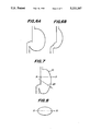
- FIG. 7 is a schematic view illustrating an organ mark on which an ultrasonic wave transmitting point indicating mark is indicated in a superimposition manner
- FIG. 8 is a schematic view for explaining the function of the organ mark shown in FIG. 7;
- FIG. 9 is a plan view illustrating an embodiment of the selection unit shown in FIG. 5;
- FIG. 10 is a schematic view showing an example of a composite image displayed on the monitor screen
- FIG. 11 is a schematic view depicting an example of the posture mark group
- FIG. 12 is a schematic view representing an example of the organ mark group
- FIG. 13 is a block diagram illustrating the construction of a third embodiment of the ultrasonic diagnosing apparatus according to the invention.
- FIG. 14 is a block diagram showing the construction of a fourth embodiment of the apparatus according to the invention.
- FIGS. 15 to 20 are schematic views depicting examples of the composite images displayed on the monitor screen.
- FIG. 2 is a block diagram showing the construction of a first embodiment of the ultrasonic diagnosing apparatus according to the present invention.
- a transmitting pulse is generated by a transmitting-receiving circuit 12 and is supplied to an ultrasonic vibrator (not shown) provided in a distal end of an ultrasonic probe 13 which is contracted to be insertable into a cavity of a patient under inspection.
- an ultrasonic vibrator not shown
- a pulsatory ultrasonic wave is transmitted from the ultrasonic probe 13 toward a cavity wall, and an ultrasonic wave reflected by the cavity wall is received by the ultrasonic vibrator in the probe 13 and is converted into an echo signal.
- the echo signal is supplied to the transmitting-receiving circuit 12 and is processed thereby in a usual manner. Then the echo signal is further supplied to a digital scan converter (DSC) 14 to which position information is also supplied from the controller 11. In DSC 14 the echo signal is processed and is converted into an ultrasonic image signal. The thus generated ultrasonic image signal is stored in DSC 14, and is then supplied to a monitor 15 to display thereon an ultrasonic image of the cavity of the patient. It should be noted that the ultrasonic probe 13 may be detachably coupled with a main body 16 of the ultrasonic diagnosing apparatus.
- DSC digital scan converter
- an image mixing circuit 17 between the digital scan converter 14 and the monitor 15 there is arranged an image mixing circuit 17. Further, a display mark memory 18 and a mark selection unit 19 are connected to the controller 11.
- the mark selection unit 19 may be formed by a keyboard.
- the memory 18 there are previously stored a plurality of posture marks 20 as shown in FIGS. 3A, 3B and 3C which represent various postures of a patient on a bed, and a plurality of organ marks.
- FIG. 4 there is shown an example of the organ mark 21 which represents a stomach.
- an operator or doctor manually selects one of the posture marks 20 as well as one of the organ marks 21 by operating the mark selection unit 19. Then, the corresponding posture mark and organ mark are read out of the memory 18 under the control of the controller 11. Then, image signals representing the thus read out marks are supplied to the mixing circuit 17 and are mixed with the ultrasonic image signal to produce a composite image signal of the ultrasonic image signal and the mark signals. Then, the composite image signal is supplied to the monitor 15 and a composite image of the ultrasonic image and the posture and organ marks 20 and 21 is displayed on a display screen of the monitor.
- the operator or doctor knows the posture of the patient on the bed and the organ of the patient under inspection and selects manually corresponding posture mark 20 and organ mark 21 by operating the mark selection unit 19. Then, the thus selected posture mark 20 and organ mark 21 are displayed on the monitor 15 together with the ultrasonic image. Therefore, it can be easily known that what portion of the patient is monitored from what direction by the ultrasonic probe 13, so that the diagnosis can be performed easily and accurately by monitoring the composite image displayed on the monitor screen.
- the composite image signal may be transmitted from the testing room in which the patient and operator are existing to the diagnosing room in which one or more doctors are existing and the composite image may be displayed on a monitor provided in the diagnosing room.
- the composite image signal may be recorded on a video tape and the composite signal may be reproduced later on in any desired room. Further the composite image may be recorded on a photographic film and after developing the film, the diagnosis may be carried out by watching the composite image on the photographic film.
- FIG. 5 is a block diagram illustrating a second embodiment of the ultrasonic diagnosing apparatus according to the invention. Portions of the present embodiment similar to those of the previous embodiment shown in FIG. 2 are denoted by the same reference numerals used in FIG. 2.
- an ultrasonic wave transmitting point indicating mark generating unit 22 for generating a signal which represents an ultrasonic wave transmitting point mark.
- This unit 22 is connected to the controller 11 and to the image mixing circuit 17.
- the unit 22 By operating the mark selection unit 19, the unit 22 generates an ultrasonic wave generating point indication signal under the control of the controller 11 and the thus generated signal is supplied to the image signal mixing circuit 17 and is mixed with the composite image signal of ultrasonic image signal and mark signals.
- the shape and size of organs are different from each other depending on the sex, male or female and the races.
- the white race has a stomach typically shown by a stomach mark shown in FIG. 6A and the stomach of the yellow race may be typically represented by a stomach mark illustrated in FIG. 6B.
- the shape and size of the stomach of the white race differ from those of the yellow race. Therefore, in the present embodiment, a plurality of organ marks belonging to the same organ are previously stored in the mark memory 18 and any desired one of the organ marks is selected by the mark selection unit 19.
- the remaining construction of the present embodiment is similar to that of the previous embodiment.
- an organ mark 21 is selectively displayed on the monitor 15 together with the ultrasonic image and at the same time a mark 23 for indicating the point and direction from and in which the ultrasonic wave is transmitted is displayed in a superimposed manner on the organ mark 21.
- the ultrasonic wave propagating medium such as water is existing on a part of the stomach which is near the back of the patient. That is to say, when a cross sectional of the stomach cut along a line X-Y in FIG. 7 is considered as shown in FIG. 8, it is known that the water is existent in an upper portion of the stomach.
- FIG. 9 is plan view depicting an embodiment of the mark selection unit 19.
- the mark selection unit 19 comprises a group of input keys 51 for entering various kinds of patient data such as the sex and race of the patient, a switch 52 for generating a group of organ marks, a switch 53 for generating a group of posture marks, mark selection switches 54 for selecting organ and posture marks, switches 55 for moving and rotating the ultrasonic wave transmitting point indicating mark 23, and a switch 56 for changing the function of the switches 55 between the linear movement and the rotation.
- FIG. 10 is a schematic view showing an example of the composite image displayed on the display screen of the monitor 15.
- ultrasonic image 61 On the screen of the monitor 15 there are displayed ultrasonic image 61, gray scale bar 62, and range scale 63.
- the switch 53 on the mark selection unit 19 is operated to display a group of posture marks on the mark group display region 65 as depicted in FIG. 11. Then, a desired posture mark is selected by operating any one of the mark selection switches 54, and a selected posture mark 20 is read out of the mark memory 18 and is displayed in the mark display region 64 of the display screen of the monitor.
- the switch 52 is operated, the group of organ marks 21 is displayed on the mark group display region 65 as illustrated in FIG. 12. In this case, organ marks corresponding to the previously entered sex and race data of the patient are selectively read out of the mark memory 18.
- a desired one of the mark selection switches 54 is operated to select a desired organ mark and the thus selected organ mark 21 is read out of the mark memory 18 and is displayed on the mark display region 64 in the display screen.
- the ultrasonic wave transmitting point indicating mark 23 is displayed on the organ mark 21 displayed in the mark display region 64 by suitably operating the linear movement-rotation changing switch 56 as well as the movement-rotation switches 55. That is to say, at first an indication mark in the form of a bar is displayed on the screen. Then, the switch 56 is operated to set the switches 55 into the linear-movement mode and the indication mark is parallelly shifted by operating the switches 55. After the indication mark is shifted into a desired position, the switch 56 is operated to change the mode of the switches 55 into the rotation mode, and the indication mark is rotated by operating the switches 55.
- the composite image including the ultrasonic image 61, posture mark 20, organ mark 21 and ultrasonic wave transmitting point indicating mark 23 as shown in FIG. 10 can be displayed on the display screen of the monitor 15. Therefore, one can understand what part of what organ of the patient is taken as the ultrasonic image, so that a very accurate diagnosis can be performed by monitoring the composite image.
- FIG. 13 is a block diagram showing a third embodiment of the ultrasonic diagnosing apparatus according to the invention. Also in the present embodiment, portions similar to those shown in FIG. 2 are denoted by the same reference numerals used in FIG. 2. In the present embodiment, the organ mark 21 is automatically selected instead of the manual selection. To this end, there is provided a scope code judging device 31 for automatically judging a kind of the ultrasonic probe 13, and in the ultrasonic probe 13 there is provided a scope code generating device. When the ultrasonic prove 13 is coupled with the main body 16, the scope code judging device 31 detects a scope code generated by the scope code generating device provided in the ultrasonic probe 13. The thus detected scope code is supplied to the controller 11. Then, the controller 11 operates to automatically select a desire organ mark from the group of organ marks stored in the memory 18. The remaining construction of the present embodiment is same as that of the first embodiment illustrated in FIG. 2.
- the organ mark is automatically selected by coupling the ultrasonic probe 13 to the main body 16, so that the operation of the operator becomes simple. Further a possible error in the manual selection of the organ mark can be effectively prevented.
- FIG. 14 is a block diagram showing a fourth embodiment of the ultrasonic diagnosing apparatus according to the invention.
- the ultrasonic wave transmitting point indicating mark 23 is automatically generated by detecting the movement of the angle knob (not shown) provided in the ultrasonic probe 13 for moving a distal end of the ultrasonic probe and a length of a portion of an insertion section of the ultrasonic probe 13 which has been inserted into the cavity of the patient.
- the ultrasonic probe 13 is constructed to generate up/down and right/left signals in relation to the operation of the angle knob and the length of the insertion section of the probe which has been inserted into the cavity, and in the main body 16 there is arranged a distal end position sensor 41 for detecting the movement of the angle knob of the ultrasonic probe 13 and a point within the cavity up to which the distal end of the probe has been inserted.
- An output signal of the distal end position sensor 41 is supplied to the controller 11, and the controller controls the ultrasonic wave transmitting point indicating mark generating device 22 to produce automatically an ultrasonic wave transmitting point indicating mark signal related to the operation of the angle knob of the ultrasonic probe and the length of the insertion section of the probe which has been inserted into the cavity.
- the manual operation of the operator can be saved and any possible error due to the manual operation can be avoided.
- FIGS. 15 to 20 show some examples of the composite image displayed on the display screen of the monitor. It should be noted that in these composite images the posture mark is not included.
- FIG. 15 there is displayed an ultrasonic image of a colon having a polyp 106 and at the same time there is displayed a colon mark 103 at a left lower region of the monitor screen.
- FIG. 16 is an enlarged view of the colon mark 103 shown in FIG. 15.
- an ultrasonic wave transmitting point indicating mark 104 indicating a point and a direction from and in which the ultrasonic wave is transmitted.
- the ultrasonic image is displayed as a three-dimensional image by processing the echo signal while a distal end of the ultrasonic probe of the radial scanning type is linearly moved within a cavity.
- an organ mark 103 In a left lower portion of the display screen, there is also displayed an organ mark 103.
- FIG. 18 is an enlarged view of the organ mark 103 shown in FIG. 17.
- the organ mark 103 is also displayed as a simple three-dimensional image and a point of the organ under inspection is displayed by an area mark 105.
- FIG. 19 is a three-dimensional ultrasonic image which is obtained by rotating the three-dimensional ultrasonic image illustrated in FIG. 17.
- a three-dimensional organ mark 103 In a right lower portion of the display screen there is displayed a three-dimensional organ mark 103. As shown in FIG. 20 the organ mark is also rotated in relation to the rotation of the ultrasonic three-dimensional ultrasonic image.
- the position and direction of the ultrasonic wave transmitting point indicating mark 104 may be set by operating a suitable operating member such as a track ball. Further the rotation of the ultrasonic image shown in FIGS. 17 and 19 may be performed by operating the track ball. In this case, the organ mark 103 is also rotated accordingly, so that the position and size of the polyp can be judged in an easy and accurate manner. Further the relative position of the polyp with respect to ambient organs and blood vessels can be understood at a glance, and thus the diagnosis can be performed precisely and a very large amount of useful data for diagnosis and surgical operation can be obtained.
- the ultrasonic image is displayed together with the posture mark, organ mark and ultrasonic wave transmitting point mark, so that the doctor can recognize a point of an organ under inspection and can effect an accurate diagnosis in an easy and accurate manner.
Applications Claiming Priority (4)
| Application Number | Priority Date | Filing Date | Title |
|---|---|---|---|
| JP3-55575 | 1991-02-28 | ||
| JP5557591 | 1991-02-28 | ||
| JP4-17643 | 1992-02-03 | ||
| JP1764392A JP3145164B2 (ja) | 1991-02-28 | 1992-02-03 | 超音波診断装置 |
Publications (1)
| Publication Number | Publication Date |
|---|---|
| US5211167A true US5211167A (en) | 1993-05-18 |
Family
ID=26354201
Family Applications (1)
| Application Number | Title | Priority Date | Filing Date |
|---|---|---|---|
| US07/838,920 Expired - Lifetime US5211167A (en) | 1991-02-28 | 1992-02-21 | Ultrasonic diagnosing apparatus |
Country Status (4)
| Country | Link |
|---|---|
| US (1) | US5211167A (de) |
| EP (1) | EP0501819B1 (de) |
| JP (1) | JP3145164B2 (de) |
| DE (1) | DE69215927T2 (de) |
Cited By (14)
| Publication number | Priority date | Publication date | Assignee | Title |
|---|---|---|---|---|
| US5315999A (en) * | 1993-04-21 | 1994-05-31 | Hewlett-Packard Company | Ultrasound imaging system having user preset modes |
| US5398685A (en) * | 1992-01-10 | 1995-03-21 | Wilk; Peter J. | Endoscopic diagnostic system and associated method |
| US5617858A (en) * | 1994-08-30 | 1997-04-08 | Vingmed Sound A/S | Apparatus for endoscopic or gastroscopic examination |
| US5660179A (en) * | 1995-04-18 | 1997-08-26 | Fujitsu Limited | Ultrasonic diagnostic apparatus |
| US5782766A (en) * | 1995-03-31 | 1998-07-21 | Siemens Medical Systems, Inc. | Method and apparatus for generating and displaying panoramic ultrasound images |
| US6122967A (en) * | 1998-06-18 | 2000-09-26 | The United States Of America As Represented By The United States Department Of Energy | Free motion scanning system |
| US20040122310A1 (en) * | 2002-12-18 | 2004-06-24 | Lim Richard Y. | Three-dimensional pictograms for use with medical images |
| US20050090746A1 (en) * | 2003-10-14 | 2005-04-28 | Aloka Co., Ltd. | Ultrasound diagnosis apparatus |
| US20050119569A1 (en) * | 2003-10-22 | 2005-06-02 | Aloka Co., Ltd. | Ultrasound diagnosis apparatus |
| US20060173325A1 (en) * | 2003-02-28 | 2006-08-03 | Morio Nishigaki | Ultrasonographic display device |
| US20100191114A1 (en) * | 2009-01-28 | 2010-07-29 | Medison Co., Ltd. | Image indicator provision in an ultrasound system |
| EP2359742A1 (de) * | 2009-11-19 | 2011-08-24 | Olympus Medical Systems Corp. | Medizingerätesystem, eingekapseltes medizingerätesystem und verfahren zur anzeige von positionierungsstellen am zu testenden körper |
| EP2491865A1 (de) * | 2011-02-24 | 2012-08-29 | Samsung Medison Co., Ltd. | Ultraschallsystem zum Bereitstellen einer Bildanzeige |
| CN108013900A (zh) * | 2017-11-30 | 2018-05-11 | 无锡祥生医疗科技股份有限公司 | 超声成像标记方法及其系统 |
Families Citing this family (6)
| Publication number | Priority date | Publication date | Assignee | Title |
|---|---|---|---|---|
| US6142940A (en) | 1998-10-06 | 2000-11-07 | Scimed Life Systems, Inc. | Control panel for intravascular ultrasonic imaging system |
| JP4533494B2 (ja) * | 2000-02-18 | 2010-09-01 | 株式会社東芝 | 超音波画像診断装置 |
| KR20120046539A (ko) * | 2010-11-02 | 2012-05-10 | 삼성메디슨 주식회사 | 바디 마크를 제공하는 초음파 시스템 및 방법 |
| JP6012288B2 (ja) * | 2012-06-27 | 2016-10-25 | 株式会社日立製作所 | 超音波診断装置 |
| KR102416511B1 (ko) * | 2014-12-23 | 2022-07-05 | 삼성메디슨 주식회사 | 바디 마커를 생성하는 방법 및 장치. |
| CN105662466A (zh) * | 2016-01-11 | 2016-06-15 | 深圳开立生物医疗科技股份有限公司 | 一种体位图、添加方法、控制装置及其超声设备 |
Citations (7)
| Publication number | Priority date | Publication date | Assignee | Title |
|---|---|---|---|---|
| US4062237A (en) * | 1976-05-07 | 1977-12-13 | Fox Martin D | Crossed beam ultrasonic flowmeter |
| JPS59222140A (ja) * | 1983-05-31 | 1984-12-13 | 株式会社東芝 | 超音波診断装置 |
| US4501277A (en) * | 1981-11-12 | 1985-02-26 | Tokyo Shibaura Denki Kabushiki Kaisha | Selected beam marking system for rapid ultrasound measurements |
| JPS6072541A (ja) * | 1983-09-29 | 1985-04-24 | 株式会社島津製作所 | 超音波診断装置の診断部位表示方法 |
| US4671292A (en) * | 1985-04-30 | 1987-06-09 | Dymax Corporation | Concentric biopsy probe |
| JPS63317140A (ja) * | 1987-06-19 | 1988-12-26 | Toshiba Corp | 超音波診断装置 |
| US4991604A (en) * | 1988-04-09 | 1991-02-12 | Richard Wolf Gmbh | Ultrasonic treatment apparatus |
Family Cites Families (3)
| Publication number | Priority date | Publication date | Assignee | Title |
|---|---|---|---|---|
| EP0083973A1 (de) * | 1982-01-07 | 1983-07-20 | Technicare Corporation | Einrichtung zur Lokalisierung einer Ultraschallsonde |
| EP0127157B2 (de) * | 1983-05-25 | 1993-06-09 | Aloka Co. Ltd. | Ultraschall-Diagnose-Vorrichtung |
| JPS60199437A (ja) * | 1984-03-24 | 1985-10-08 | 株式会社東芝 | 超音波診断装置 |
-
1992
- 1992-02-03 JP JP1764392A patent/JP3145164B2/ja not_active Expired - Fee Related
- 1992-02-21 US US07/838,920 patent/US5211167A/en not_active Expired - Lifetime
- 1992-02-28 EP EP19920301716 patent/EP0501819B1/de not_active Expired - Lifetime
- 1992-02-28 DE DE1992615927 patent/DE69215927T2/de not_active Expired - Fee Related
Patent Citations (7)
| Publication number | Priority date | Publication date | Assignee | Title |
|---|---|---|---|---|
| US4062237A (en) * | 1976-05-07 | 1977-12-13 | Fox Martin D | Crossed beam ultrasonic flowmeter |
| US4501277A (en) * | 1981-11-12 | 1985-02-26 | Tokyo Shibaura Denki Kabushiki Kaisha | Selected beam marking system for rapid ultrasound measurements |
| JPS59222140A (ja) * | 1983-05-31 | 1984-12-13 | 株式会社東芝 | 超音波診断装置 |
| JPS6072541A (ja) * | 1983-09-29 | 1985-04-24 | 株式会社島津製作所 | 超音波診断装置の診断部位表示方法 |
| US4671292A (en) * | 1985-04-30 | 1987-06-09 | Dymax Corporation | Concentric biopsy probe |
| JPS63317140A (ja) * | 1987-06-19 | 1988-12-26 | Toshiba Corp | 超音波診断装置 |
| US4991604A (en) * | 1988-04-09 | 1991-02-12 | Richard Wolf Gmbh | Ultrasonic treatment apparatus |
Cited By (22)
| Publication number | Priority date | Publication date | Assignee | Title |
|---|---|---|---|---|
| US5398685A (en) * | 1992-01-10 | 1995-03-21 | Wilk; Peter J. | Endoscopic diagnostic system and associated method |
| US5315999A (en) * | 1993-04-21 | 1994-05-31 | Hewlett-Packard Company | Ultrasound imaging system having user preset modes |
| US5617858A (en) * | 1994-08-30 | 1997-04-08 | Vingmed Sound A/S | Apparatus for endoscopic or gastroscopic examination |
| US5782766A (en) * | 1995-03-31 | 1998-07-21 | Siemens Medical Systems, Inc. | Method and apparatus for generating and displaying panoramic ultrasound images |
| US5660179A (en) * | 1995-04-18 | 1997-08-26 | Fujitsu Limited | Ultrasonic diagnostic apparatus |
| US6122967A (en) * | 1998-06-18 | 2000-09-26 | The United States Of America As Represented By The United States Department Of Energy | Free motion scanning system |
| US6991605B2 (en) * | 2002-12-18 | 2006-01-31 | Siemens Medical Solutions Usa, Inc. | Three-dimensional pictograms for use with medical images |
| US20040122310A1 (en) * | 2002-12-18 | 2004-06-24 | Lim Richard Y. | Three-dimensional pictograms for use with medical images |
| US20060173325A1 (en) * | 2003-02-28 | 2006-08-03 | Morio Nishigaki | Ultrasonographic display device |
| US20050090746A1 (en) * | 2003-10-14 | 2005-04-28 | Aloka Co., Ltd. | Ultrasound diagnosis apparatus |
| CN1606966B (zh) * | 2003-10-14 | 2010-09-29 | 阿洛卡株式会社 | 超声波诊断装置 |
| US7806824B2 (en) | 2003-10-22 | 2010-10-05 | Aloka Co., Ltd. | Ultrasound diagnosis apparatus |
| US20050119569A1 (en) * | 2003-10-22 | 2005-06-02 | Aloka Co., Ltd. | Ultrasound diagnosis apparatus |
| US9211105B2 (en) | 2009-01-28 | 2015-12-15 | Samsung Medison Co., Ltd. | Image indicator provision in an ultrasound system |
| US20100191114A1 (en) * | 2009-01-28 | 2010-07-29 | Medison Co., Ltd. | Image indicator provision in an ultrasound system |
| EP2213240A1 (de) * | 2009-01-28 | 2010-08-04 | Medison Co., Ltd. | Bildanzeigebereitstellung in einem Ultraschallsystem |
| EP2359742A1 (de) * | 2009-11-19 | 2011-08-24 | Olympus Medical Systems Corp. | Medizingerätesystem, eingekapseltes medizingerätesystem und verfahren zur anzeige von positionierungsstellen am zu testenden körper |
| EP2359742A4 (de) * | 2009-11-19 | 2012-08-29 | Olympus Medical Systems Corp | Medizingerätesystem, eingekapseltes medizingerätesystem und verfahren zur anzeige von positionierungsstellen am zu testenden körper |
| EP2491865A1 (de) * | 2011-02-24 | 2012-08-29 | Samsung Medison Co., Ltd. | Ultraschallsystem zum Bereitstellen einer Bildanzeige |
| US8777855B2 (en) | 2011-02-24 | 2014-07-15 | Samsung Medison Co., Ltd. | Ultrasound system for providing image indicator |
| CN108013900A (zh) * | 2017-11-30 | 2018-05-11 | 无锡祥生医疗科技股份有限公司 | 超声成像标记方法及其系统 |
| CN108013900B (zh) * | 2017-11-30 | 2021-02-05 | 无锡祥生医疗科技股份有限公司 | 超声成像标记方法及其系统 |
Also Published As
| Publication number | Publication date |
|---|---|
| EP0501819A3 (en) | 1993-04-21 |
| DE69215927D1 (de) | 1997-01-30 |
| EP0501819B1 (de) | 1996-12-18 |
| EP0501819A2 (de) | 1992-09-02 |
| JP3145164B2 (ja) | 2001-03-12 |
| JPH05111488A (ja) | 1993-05-07 |
| DE69215927T2 (de) | 1997-05-15 |
Similar Documents
| Publication | Publication Date | Title |
|---|---|---|
| US5211167A (en) | Ultrasonic diagnosing apparatus | |
| US5551434A (en) | Ultrasonic imaging diagnosis apparatus | |
| KR100946826B1 (ko) | 시스템 컨트롤러 | |
| US5090411A (en) | Ultrasonic diagnosis apparatus | |
| US5224481A (en) | Image displaying method and device for realizing same in an ultrasonic diagnostic apparatus | |
| JPH0584248A (ja) | 循環器用診断装置 | |
| CN111671461B (zh) | 超声波诊断装置及显示方法 | |
| JP4879623B2 (ja) | 超音波診断装置 | |
| KR100740378B1 (ko) | 초음파 진단 장치 | |
| JPS63290550A (ja) | 穿刺針案内用超音波断層装置 | |
| JPH10151133A (ja) | 医用画像診断装置 | |
| JP2004057379A (ja) | 超音波診断装置 | |
| EP0157302B1 (de) | Ultraschallabbildungsvorrichtung mit Massstabssteuerung | |
| JP2005000390A (ja) | 超音波診断装置 | |
| JPH0665338B2 (ja) | 超音波診断装置 | |
| JPH11318904A (ja) | 超音波診断装置 | |
| JP2005006770A (ja) | 超音波診断装置 | |
| JP4533494B2 (ja) | 超音波画像診断装置 | |
| JPH08238209A (ja) | 挿入深さ検出装置 | |
| KR20070029366A (ko) | 분리 가능한 터치 스크린을 갖는 초음파 진단 시스템 및이를 제어하는 방법 | |
| JP2005288043A (ja) | 医療画像診断装置 | |
| JP7447692B2 (ja) | 超音波診断装置、超音波診断装置の制御方法、及び、超音波診断装置の制御プログラム | |
| JPH07184906A (ja) | 超音波診断装置 | |
| JP3630403B2 (ja) | 超音波診断装置 | |
| JPH10248852A (ja) | 超音波画像診断装置 |
Legal Events
| Date | Code | Title | Description |
|---|---|---|---|
| AS | Assignment |
Owner name: OLYMPUS OPTICAL CO., LTD., JAPAN Free format text: ASSIGNMENT OF ASSIGNORS INTEREST.;ASSIGNOR:AMENOMORI, TAKESHI;REEL/FRAME:006029/0195 Effective date: 19920217 |
|
| STCF | Information on status: patent grant |
Free format text: PATENTED CASE |
|
| FEPP | Fee payment procedure |
Free format text: PAYOR NUMBER ASSIGNED (ORIGINAL EVENT CODE: ASPN); ENTITY STATUS OF PATENT OWNER: LARGE ENTITY |
|
| FPAY | Fee payment |
Year of fee payment: 4 |
|
| FPAY | Fee payment |
Year of fee payment: 8 |
|
| FPAY | Fee payment |
Year of fee payment: 12 |