US5087280A - Floating mold changer carriage - Google Patents
Floating mold changer carriage Download PDFInfo
- Publication number
- US5087280A US5087280A US07/402,898 US40289888A US5087280A US 5087280 A US5087280 A US 5087280A US 40289888 A US40289888 A US 40289888A US 5087280 A US5087280 A US 5087280A
- Authority
- US
- United States
- Prior art keywords
- main frame
- mold
- floating
- carriage
- wheels
- Prior art date
- Legal status (The legal status is an assumption and is not a legal conclusion. Google has not performed a legal analysis and makes no representation as to the accuracy of the status listed.)
- Expired - Fee Related
Links
- 239000012530 fluid Substances 0.000 claims abstract description 33
- 238000007493 shaping process Methods 0.000 claims abstract description 19
- 239000011521 glass Substances 0.000 claims abstract description 16
- 238000003860 storage Methods 0.000 claims abstract description 9
- 239000012858 resilient material Substances 0.000 claims abstract description 3
- 238000007599 discharging Methods 0.000 claims description 2
- 238000010438 heat treatment Methods 0.000 description 4
- 238000004519 manufacturing process Methods 0.000 description 4
- 230000006835 compression Effects 0.000 description 3
- 238000007906 compression Methods 0.000 description 3
- 238000000034 method Methods 0.000 description 2
- 239000000725 suspension Substances 0.000 description 2
- 229910000831 Steel Inorganic materials 0.000 description 1
- 230000000740 bleeding effect Effects 0.000 description 1
- 239000003638 chemical reducing agent Substances 0.000 description 1
- 238000009434 installation Methods 0.000 description 1
- 230000002093 peripheral effect Effects 0.000 description 1
- 238000003825 pressing Methods 0.000 description 1
- 230000000284 resting effect Effects 0.000 description 1
- 239000010959 steel Substances 0.000 description 1
- XLYOFNOQVPJJNP-UHFFFAOYSA-N water Substances O XLYOFNOQVPJJNP-UHFFFAOYSA-N 0.000 description 1
Images


Classifications
-
- C—CHEMISTRY; METALLURGY
- C03—GLASS; MINERAL OR SLAG WOOL
- C03B—MANUFACTURE, SHAPING, OR SUPPLEMENTARY PROCESSES
- C03B23/00—Re-forming shaped glass
- C03B23/02—Re-forming glass sheets
- C03B23/023—Re-forming glass sheets by bending
- C03B23/03—Re-forming glass sheets by bending by press-bending between shaping moulds
-
- C—CHEMISTRY; METALLURGY
- C03—GLASS; MINERAL OR SLAG WOOL
- C03B—MANUFACTURE, SHAPING, OR SUPPLEMENTARY PROCESSES
- C03B35/00—Transporting of glass products during their manufacture, e.g. hot glass lenses, prisms
- C03B35/14—Transporting hot glass sheets or ribbons, e.g. by heat-resistant conveyor belts or bands
- C03B35/20—Transporting hot glass sheets or ribbons, e.g. by heat-resistant conveyor belts or bands by gripping tongs or supporting frames
Definitions
- the present invention relates to an apparatus for manufacturing curved sheets of glass with upper and lower molds, and more particularly to a mold changer carriage for changing such upper and lower molds altogether.
- Curved sheets of glass for use as automobile windshields are manufactured by an apparatus as disclosed in Japanese Patent Publication No. 53-12931, for example.
- the disclosed manufacturing apparatus has a heating furnace for heating a sheet of glass up to a temperature near its softening point.
- the heated glass sheet is delivered horizontally to a position between upper and lower molds of a shaping device by feed rollers.
- the glass sheet is then positioned between the upper and lower molds, and the lower mold is lifted above the feed rollers to place the glass sheet on the lower mold. Thereafter, the upper mold is lowered into pressing contact with the glass sheet on the lower mold for curving the glass sheet to a desired curved shape.
- the upper and lower molds in the shaping device are replaced with another set of upper and lower molds.
- the process of removing the existing molds from the shaping assembly and replacing them with new molds is however very complex and time-consuming.
- the upper and lower molds are fixedly mounted on attachment plates fixed to lifting/lowering devices or hydraulic cylinders.
- they are detached from the respective attachment plates and delivered to a given storage area for storage.
- a new upper mold stored in another storage area is carried into the shaping device, and lifted and attached to the attachment plate therefor, and a new lower mold is similarly delivered from the storage area into the shaping device and attached to the corresponding attachment plate.
- the upper and lower molds are registered with each other.
- Japanese Laid-Open Patent Publication No. 62-182124 discloses a mold changer for use with an apparatus for manufacturing curved sheets of glass.
- the disclosed mold changer includes a carrier plate having a number of steel balls on its upper surface.
- Upper and lower attachment plates which are interconnected by positioning rods are placed on the carrier plate, the upper and lower attachment plates supporting upper and lower molds, respectively.
- the carrier plate By moving the carrier plate along rails, the upper and lower molds can simultaneously be moved between a shaping device and their storage location.
- problems with this mold changer are that a wide floor space is needed for the installation of the rails, the mold changer itself tends to interfere with various other operations, and when large molds are to be replaced or used, considerably large forces are required to move the molds.
- a floating mold changer carriage for movement between a shaping device for shaping a sheet of glass with at least one mold and a mold storage area spaced from the shaping device, for replacing the mold with a new mold
- the floating mold changer carriage comprising a main frame, a fluid source for supplying a fluid, first means connected to the fluid source for discharging the fluid supplied from the fluid source, downwardly from a lower surface of the main frame; and second means coacting with the first means and inflatable for floating the main frame when the second means is supplied with the fluid therein.
- the first means comprises a plurality of pallets attached to the lower surface of the main frame, each of the pallets having a flow passage defined therein and having one open end connected to the fluid source and the other open end opening toward a floor.
- the second comprises hollow annular members disposed around central cylindrical portions of the pallets, each of the annular members having an opening confronting the other open end of the flow passage.
- the fluid is air but may be water.
- the annular members are inflated to float the entire carriage off the floor. The coefficient of friction between the floor and the annular members is lowered to allow the carriage to be moved with ease.
- a plurality of wheels are rotatably mounted on the lower surface of the main frame. By orienting the wheels in a desired direction, the direction of movement of the carriage can be controlled so as to prevent the carriage from being displaced laterally off the desired direction.
- FIG. 1 is a front elevational view of a floating carriage according to the present invention, with molds supported respectively on attachment plates;
- FIG. 2 is a plan view of the floating carriage
- FIG. 3 is a bottom view of the floating carriage
- FIG. 4 is a schematic view of a fluid supply system for supplying a fluid to pallets of the floating carriage
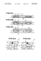
- FIGS. 5A through 5C are cross-sectional views showing the manner in which the pallets are operated.
- FIGS. 6A and 6B are views showing operation of a wheel attached to the floating carriage
- FIG. 7 is a front elevational view of a frame assembly of a shaping device.
- FIG. 8 is a front elevational view of the floating carriage which is positioned in the frame assembly illustrated in FIG. 7.
- a floating carriage 10 has a main frame 12 comprising an upper plate 12a which is substantially square in shape as viewed in plan, vertical plates 12b extending downwardly from opposite sides of the lower surface of the upper plate 12a, and a lower plate 12c extending between and joined to the lower ends of the vertical plates 12b.
- a central preassembled frame 14 is mounted centrally in the main frame 12 and projects upwardly above the upper surface of the upper plate 12a.
- a cylinder unit 16 is mounted as a lifting/lowering device on the central frame 14. The cylinder unit 16 serves to lift and lower a lower support base 20 while the latter is being guided by guide members 18.
- the upper plate 12a supports thereon a motor 22.
- Drive power from the motor 22 is transmitted to a support frame 24 via a speed reducer mechanism 28 and an oscillator mechanism 26 that includes a plurality of rails 30, for enabling the support frame 24 to make circular motion, elliptical motion, or rectilinear motion in a horizontal plane.
- the support frame 24 supports on its upper end a ring mold 32 for shaping the outer peripheral edge of a sheet of glass.
- the lower support base 20 has a plurality of clamps 34 on its side edges for reliably gripping a lower attachment plate 36.
- An upper attachment plate 38 is connected to the lower attachment plate 38 in vertically spaced relation by a plurality of vertical connecting rods 40.
- a lower mold 42 is mounted on the lower attachment plate 36, and an upper mold 44 is mounted on the upper attachment plate 38.
- a plurality of pallets 50 are fixed to the lower surface of the lower plate 12c of the main frame 12.
- Each of the pallets 50 comprises a horizontal plate having a certain vertical thickness and a square shape as viewed in plan, and a cylindrical portion 52 projecting downwardly from the bottom thereof and normally resting on a floor 76.
- the pallet 50 has a flow passage 54 for passage of a fluid therethrough, the flow passage 54 being connected to a fluid source 56 through a hose 58 in a fluid supply system as shown in FIG. 4.
- a hollow annular member 70 made of a resilient material is disposed around the cylindrical portion 52 and has an opening 72 defined below an outlet 74 at one end of the flow passage 54.
- brackets 80 are mounted on the lower surface of the lower plate 12c.
- An arm 82 is pivotally attached to the lower free end of each of the brackets 80.
- a compression spring 84 is disposed under compression between the arm 82 and the lower plate 12c for normally urging the arm 82 downwardly.
- the arm 82 is pressed downwardly under the resiliency of the compression spring 84 to cause a wheel 86 rotatably mounted on the distal end of the arm 82 to contact the floor 76.
- a rod 88 extends vertically through the arm 82 and supports a rubber pad 90 on its lower end.
- a semispherical member 92 is fixed to an intermediate portion of the rod 88.
- FIG. 7 shows a frame assembly 96 of a shaping device disposed adjacent to a heating furnace 94.
- the frame assembly 96 comprises a plurality of vertical frames 96a and an upper horizontal plate 96b fixed to the upper ends of the vertical frames 96a.
- a cylinder unit 98 is disposed on the upper surface of the upper plate 96b and includes a rod 100 having a lower end coupled to a joint member of an upper support base 102 for vertically moving the upper support base 102.
- the upper support base 102 has a plurality of clamps 104 for reliably gripping the upper attachment plate 38 with the upper mold 44 mounted thereon.
- a new upper mold is attached to the upper attachment plate 38 and a new lower mold is attached to the lower attachment plate 36.
- the lower mold is placed on the lower support base 20 by a suitable suspension device, and securely fixed to the lower support base 20 by the clamps 34.
- the upper attachment plate 38 is lifted above the lower mold 42 by the same suspension device, and the upper and lower attachment plates 36, 38 are interconnected by the connecting rods 40.
- air under pressure is supplied from the fluid source 56 into each of the annular members 70.
- the annular members 70 are inflated to lift the carriage 10 off the floor 76.
- the carriage 10 can thus be moved in its entirety to the frame assembly 96 by applying a relatively small force to the carriage 10. With the wheels 86 fixedly oriented to a certain direction, the carriage 10 is prevented from being displaced in other directions than said certain direction.
- the cylinder unit 16 is actuated to elevate the lower support base 20 until the upper attachment plate 38 abuts against the upper support base 102. After the upper attachment plate 38 is held against the upper support base 102, the upper attachment plate 38 is fixed to the upper support base 102 by the clamps 104. Then, the cylinder unit 16 is operated to lower the lower support base 20, and the connecting rods 40 are removed. The carriage 10 is positioned in the frame assembly 96 at this time as shown in FIG. 8.
- a sheet of glass which has been heated to its softening point in the heating furnace 94 is received on feed rollers 106 on a receiver plate 108, installed on the carriage 10, after which the glass sheet is curved to a desired shape by the upper and lower molds 42, 44 and the ring mold 32 in the manner known in the art.
- the aforesaid process is reversed for removing the molds 42, 44 from the frame assembly 96 and replacing them with new molds. More specifically, the cylinder unit 16 is operated to lift the lower support base 20, and the upper and lower attachment plates 36, 38 are coupled to each other by the connecting rods 40. The clamps 104 are swung outwardly to release the upper attachment plate 38 from the upper support base 102. The cylinder unit 16 is operated again to lower the lower support base 20. The annular members 70 are supplied with air under pressure to float the carriage 10 off the floor, and the carriage 10 is moved to a mold storage area where a new set of upper and lower molds is stored.
Landscapes
- Chemical & Material Sciences (AREA)
- Engineering & Computer Science (AREA)
- Materials Engineering (AREA)
- Organic Chemistry (AREA)
- Re-Forming, After-Treatment, Cutting And Transporting Of Glass Products (AREA)
- Moulds For Moulding Plastics Or The Like (AREA)
- Mounting, Exchange, And Manufacturing Of Dies (AREA)
Applications Claiming Priority (2)
| Application Number | Priority Date | Filing Date | Title |
|---|---|---|---|
| JP62-308973 | 1987-12-07 | ||
| JP62308973A JPH01148720A (ja) | 1987-12-07 | 1987-12-07 | 浮上式型交換台車 |
Publications (1)
| Publication Number | Publication Date |
|---|---|
| US5087280A true US5087280A (en) | 1992-02-11 |
Family
ID=17987444
Family Applications (1)
| Application Number | Title | Priority Date | Filing Date |
|---|---|---|---|
| US07/402,898 Expired - Fee Related US5087280A (en) | 1987-12-07 | 1988-12-07 | Floating mold changer carriage |
Country Status (5)
| Country | Link |
|---|---|
| US (1) | US5087280A (show.php) |
| EP (1) | EP0320128B1 (show.php) |
| JP (1) | JPH01148720A (show.php) |
| KR (1) | KR920000669B1 (show.php) |
| DE (1) | DE3883177T2 (show.php) |
Cited By (6)
| Publication number | Priority date | Publication date | Assignee | Title |
|---|---|---|---|---|
| US6485247B1 (en) * | 2000-09-28 | 2002-11-26 | The Boeing Company | Engine uplift loader |
| US7426974B1 (en) * | 2003-04-09 | 2008-09-23 | Yeghiayan Arra D | Air bearing base and workstation |
| US8800707B1 (en) * | 2011-08-23 | 2014-08-12 | The Boeing Company | Modular system and methods for moving large heavy objects |
| CN104550447A (zh) * | 2015-01-26 | 2015-04-29 | 苏黎 | 一种热铆焊接机构的下模具快换结构 |
| CN108069583A (zh) * | 2016-11-11 | 2018-05-25 | 比亚迪股份有限公司 | 一种曲面玻璃热弯模具、曲面玻璃及其制备方法 |
| US20200039861A1 (en) * | 2018-07-31 | 2020-02-06 | Taifin Glass Machinery Oy | Method for bending glass sheets in an apparatus, and apparatus for bending glass sheets |
Families Citing this family (6)
| Publication number | Priority date | Publication date | Assignee | Title |
|---|---|---|---|---|
| JP3003132U (ja) * | 1994-04-15 | 1994-10-18 | 東光金型有限会社 | ゲートボール用スティックヘッド |
| JP4771270B2 (ja) * | 2001-01-30 | 2011-09-14 | 旭硝子株式会社 | ガラス板成形型の交換方法及びその装置 |
| SE528817C2 (sv) * | 2005-05-23 | 2007-02-20 | Camfil Ab | Påsfilteraggregat |
| JP2007185638A (ja) * | 2006-01-16 | 2007-07-26 | Akushii:Kk | バッグフィルタ |
| CN102240753A (zh) * | 2011-05-13 | 2011-11-16 | 厦门捷视光学有限公司 | 金属眼镜框体的制造工艺 |
| CN106584765A (zh) * | 2016-11-18 | 2017-04-26 | 江苏智石科技有限公司 | 一种自适应车床高度的换模台车 |
Citations (8)
| Publication number | Priority date | Publication date | Assignee | Title |
|---|---|---|---|---|
| US3457874A (en) * | 1966-09-19 | 1969-07-29 | Aida Iron Works & Co Ltd | Quick die changing system |
| US3618694A (en) * | 1969-10-06 | 1971-11-09 | Aero Go Inc | Hop-free fluid bearing of spandrel inflated flexible type |
| US3807035A (en) * | 1972-05-08 | 1974-04-30 | Ingersoll Milling Machine Co | Method of and apparatus for precision positioning of heavy workpieces |
| US3825094A (en) * | 1973-08-06 | 1974-07-23 | Rolair Syst Inc | Remote control for air bearing transporters and the like |
| US4082195A (en) * | 1976-06-21 | 1978-04-04 | Ex-Cell-O Corporation | Handling system for heavy loads |
| US4092141A (en) * | 1977-01-03 | 1978-05-30 | Ppg Industries, Inc. | Method and apparatus for handling glass sheets for shaping and cooling |
| US4273244A (en) * | 1979-01-29 | 1981-06-16 | Fmc Corporation | Crane upperstructure self-transferring system |
| GB2185974A (en) * | 1986-02-03 | 1987-08-05 | Nippon Sheet Glass Co Ltd | Apparatus for shaping glass sheet |
Family Cites Families (1)
| Publication number | Priority date | Publication date | Assignee | Title |
|---|---|---|---|---|
| JPS5749023U (show.php) * | 1980-09-03 | 1982-03-19 |
-
1987
- 1987-12-07 JP JP62308973A patent/JPH01148720A/ja active Granted
-
1988
- 1988-11-16 DE DE88310795T patent/DE3883177T2/de not_active Expired - Fee Related
- 1988-11-16 EP EP88310795A patent/EP0320128B1/en not_active Expired - Lifetime
- 1988-11-23 KR KR1019880015416A patent/KR920000669B1/ko not_active Expired
- 1988-12-07 US US07/402,898 patent/US5087280A/en not_active Expired - Fee Related
Patent Citations (9)
| Publication number | Priority date | Publication date | Assignee | Title |
|---|---|---|---|---|
| US3457874A (en) * | 1966-09-19 | 1969-07-29 | Aida Iron Works & Co Ltd | Quick die changing system |
| US3618694A (en) * | 1969-10-06 | 1971-11-09 | Aero Go Inc | Hop-free fluid bearing of spandrel inflated flexible type |
| US3807035A (en) * | 1972-05-08 | 1974-04-30 | Ingersoll Milling Machine Co | Method of and apparatus for precision positioning of heavy workpieces |
| US3825094A (en) * | 1973-08-06 | 1974-07-23 | Rolair Syst Inc | Remote control for air bearing transporters and the like |
| US4082195A (en) * | 1976-06-21 | 1978-04-04 | Ex-Cell-O Corporation | Handling system for heavy loads |
| US4092141A (en) * | 1977-01-03 | 1978-05-30 | Ppg Industries, Inc. | Method and apparatus for handling glass sheets for shaping and cooling |
| US4273244A (en) * | 1979-01-29 | 1981-06-16 | Fmc Corporation | Crane upperstructure self-transferring system |
| GB2185974A (en) * | 1986-02-03 | 1987-08-05 | Nippon Sheet Glass Co Ltd | Apparatus for shaping glass sheet |
| US4711654A (en) * | 1986-02-03 | 1987-12-08 | Nippon Sheet Glass Co., Ltd. | Apparatus for shaping glass sheet |
Cited By (9)
| Publication number | Priority date | Publication date | Assignee | Title |
|---|---|---|---|---|
| US6485247B1 (en) * | 2000-09-28 | 2002-11-26 | The Boeing Company | Engine uplift loader |
| US7426974B1 (en) * | 2003-04-09 | 2008-09-23 | Yeghiayan Arra D | Air bearing base and workstation |
| US8800707B1 (en) * | 2011-08-23 | 2014-08-12 | The Boeing Company | Modular system and methods for moving large heavy objects |
| CN104550447A (zh) * | 2015-01-26 | 2015-04-29 | 苏黎 | 一种热铆焊接机构的下模具快换结构 |
| CN104550447B (zh) * | 2015-01-26 | 2016-06-08 | 苏黎 | 一种热铆焊接机构的下模具快换结构 |
| CN108069583A (zh) * | 2016-11-11 | 2018-05-25 | 比亚迪股份有限公司 | 一种曲面玻璃热弯模具、曲面玻璃及其制备方法 |
| CN108069583B (zh) * | 2016-11-11 | 2019-12-27 | 比亚迪股份有限公司 | 一种曲面玻璃热弯模具、曲面玻璃及其制备方法 |
| US20200039861A1 (en) * | 2018-07-31 | 2020-02-06 | Taifin Glass Machinery Oy | Method for bending glass sheets in an apparatus, and apparatus for bending glass sheets |
| US11884572B2 (en) * | 2018-07-31 | 2024-01-30 | Heva Schweiz Ag | Method for bending glass sheets in an apparatus, and apparatus for bending glass sheets |
Also Published As
| Publication number | Publication date |
|---|---|
| JPH0545334B2 (show.php) | 1993-07-08 |
| KR920000669B1 (ko) | 1992-01-20 |
| JPH01148720A (ja) | 1989-06-12 |
| DE3883177T2 (de) | 1993-12-23 |
| EP0320128A3 (en) | 1990-09-05 |
| EP0320128A2 (en) | 1989-06-14 |
| EP0320128B1 (en) | 1993-08-11 |
| DE3883177D1 (de) | 1993-09-16 |
| KR890009776A (ko) | 1989-08-04 |
Similar Documents
| Publication | Publication Date | Title |
|---|---|---|
| US5087280A (en) | Floating mold changer carriage | |
| FI84996C (fi) | Foerfarande och apparat foer faestande, flyttande och staellande av skivor utav flexibelt plastmaterial. | |
| US8376730B2 (en) | Method of clamping material and a material-clamping unit used therefor | |
| WO1998034802B1 (en) | Tire inflation apparatus and method having floating platen | |
| KR20000070967A (ko) | 부양플래튼을 갖는 타이어팽창장치와 방법 | |
| CA2091162A1 (en) | Method of and apparatus for bending glass sheets | |
| CN102528978A (zh) | 轮胎硫化机的中心机构 | |
| US20020035760A1 (en) | Dock leveler having an inflatable member | |
| US6983690B2 (en) | Transfer heat press | |
| EP0692460B1 (en) | Flexible ring mould for bending glass sheets | |
| JP3872589B2 (ja) | 金型開閉・加硫ステーション | |
| JP3953095B2 (ja) | ガラスシートの位置決め装置及び方法 | |
| US5649491A (en) | Tilt table | |
| US5649990A (en) | Combination flexible/rigid ring mold | |
| CN109590738B (zh) | 车桥预装生产线 | |
| WO2017140197A1 (zh) | 一种采用移动式车辆养护站的车辆养护方法 | |
| CN222137787U (zh) | 一种刹车盘输送结构 | |
| JPH03288571A (ja) | 床コーティング剤塗布機 | |
| CN108528751B (zh) | 一种用于雪橇式直升机地面移动的搬运设备 | |
| CN208248515U (zh) | 一种用于雪橇式直升机地面移动的搬运设备 | |
| CN106426998A (zh) | 平移垂直升降翻转式后充气装置 | |
| CN223575322U (zh) | 一种钢管输送装置 | |
| CN115950512B (zh) | 一种自动称重摆转装置 | |
| CN219405535U (zh) | 双周期后充气定型机 | |
| CN222436925U (zh) | 一种混凝土自保温砌块输送线可调式摩擦轮驱动装置 |
Legal Events
| Date | Code | Title | Description |
|---|---|---|---|
| AS | Assignment |
Owner name: NIPPON SHEET GLASS CO., LTD., 5-11, DOSHO-MACHI 3- Free format text: ASSIGNMENT OF ASSIGNORS INTEREST.;ASSIGNOR:FUCHIGAMI, YASUHIRO;REEL/FRAME:005272/0612 |
|
| AS | Assignment |
Owner name: NIPPON SHEET GLASS CO., LTD.,, JAPAN Free format text: ASSIGNMENT OF ASSIGNORS INTEREST.;ASSIGNOR:FUCHIGAMI, YASUHIRO;REEL/FRAME:005834/0495 Effective date: 19910831 |
|
| FEPP | Fee payment procedure |
Free format text: PAYOR NUMBER ASSIGNED (ORIGINAL EVENT CODE: ASPN); ENTITY STATUS OF PATENT OWNER: LARGE ENTITY |
|
| FPAY | Fee payment |
Year of fee payment: 4 |
|
| FPAY | Fee payment |
Year of fee payment: 8 |
|
| REMI | Maintenance fee reminder mailed | ||
| LAPS | Lapse for failure to pay maintenance fees | ||
| FP | Lapsed due to failure to pay maintenance fee |
Effective date: 20040211 |
|
| STCH | Information on status: patent discontinuation |
Free format text: PATENT EXPIRED DUE TO NONPAYMENT OF MAINTENANCE FEES UNDER 37 CFR 1.362 |