US5083370A - Method for automatically connecting electrical conductors to contact parts in plug housings - Google Patents
Method for automatically connecting electrical conductors to contact parts in plug housings Download PDFInfo
- Publication number
- US5083370A US5083370A US07/374,271 US37427189A US5083370A US 5083370 A US5083370 A US 5083370A US 37427189 A US37427189 A US 37427189A US 5083370 A US5083370 A US 5083370A
- Authority
- US
- United States
- Prior art keywords
- gripper
- electric conductor
- contact part
- connector
- connector shell
- Prior art date
- Legal status (The legal status is an assumption and is not a legal conclusion. Google has not performed a legal analysis and makes no representation as to the accuracy of the status listed.)
- Expired - Lifetime
Links
Images


Classifications
-
- H—ELECTRICITY
- H01—ELECTRIC ELEMENTS
- H01R—ELECTRICALLY-CONDUCTIVE CONNECTIONS; STRUCTURAL ASSOCIATIONS OF A PLURALITY OF MUTUALLY-INSULATED ELECTRICAL CONNECTING ELEMENTS; COUPLING DEVICES; CURRENT COLLECTORS
- H01R43/00—Apparatus or processes specially adapted for manufacturing, assembling, maintaining, or repairing of line connectors or current collectors or for joining electric conductors
- H01R43/20—Apparatus or processes specially adapted for manufacturing, assembling, maintaining, or repairing of line connectors or current collectors or for joining electric conductors for assembling or disassembling contact members with insulating base, case or sleeve
-
- Y—GENERAL TAGGING OF NEW TECHNOLOGICAL DEVELOPMENTS; GENERAL TAGGING OF CROSS-SECTIONAL TECHNOLOGIES SPANNING OVER SEVERAL SECTIONS OF THE IPC; TECHNICAL SUBJECTS COVERED BY FORMER USPC CROSS-REFERENCE ART COLLECTIONS [XRACs] AND DIGESTS
- Y10—TECHNICAL SUBJECTS COVERED BY FORMER USPC
- Y10T—TECHNICAL SUBJECTS COVERED BY FORMER US CLASSIFICATION
- Y10T29/00—Metal working
- Y10T29/49—Method of mechanical manufacture
- Y10T29/49002—Electrical device making
- Y10T29/49117—Conductor or circuit manufacturing
- Y10T29/49174—Assembling terminal to elongated conductor
- Y10T29/49181—Assembling terminal to elongated conductor by deforming
- Y10T29/49185—Assembling terminal to elongated conductor by deforming of terminal
-
- Y—GENERAL TAGGING OF NEW TECHNOLOGICAL DEVELOPMENTS; GENERAL TAGGING OF CROSS-SECTIONAL TECHNOLOGIES SPANNING OVER SEVERAL SECTIONS OF THE IPC; TECHNICAL SUBJECTS COVERED BY FORMER USPC CROSS-REFERENCE ART COLLECTIONS [XRACs] AND DIGESTS
- Y10—TECHNICAL SUBJECTS COVERED BY FORMER USPC
- Y10T—TECHNICAL SUBJECTS COVERED BY FORMER US CLASSIFICATION
- Y10T29/00—Metal working
- Y10T29/53—Means to assemble or disassemble
- Y10T29/5313—Means to assemble electrical device
- Y10T29/532—Conductor
- Y10T29/53209—Terminal or connector
- Y10T29/53213—Assembled to wire-type conductor
- Y10T29/53235—Means to fasten by deformation
Definitions
- the invention relates to a method for the automatic mounting of electric conductors with contact parts in connector shells with a gripper system and a device for performing the method.
- a device for the mounting of electric conductors with contact parts in connector shells has been taught, for example, in the German Patent Application Laid Open DE-OS 2,740,377.
- This device where a crimp device is combined with a plug device, is a so-called rigidly chained system.
- the gripper is moved by two piston cylinder units acting perpendicular relative to each other.
- the tensioning station is actuated by a further piston cylinder unit for a connector shell.
- the connector shell itself and further actuating and support means are in an interdependent, rigid relation, which is dependent on the construction and on the predetermined motion path of the device.
- a flexible mounting of desired contact parts with conductors in arbitrary connector shells is not possible with the taught reference device.
- the present invention provides for a method for an automatic mounting of electric conductors, having contact parts, to connector shells.
- the method comprises the following process steps: At least one connector shell from a connector-shell magazine is gripped with a gripper tool supported by a gripper. Two contact parts of an electric conductor are centered at an end of a cable-processing line. The two contact parts are maintained in a rest position at the insulated conductor by respectively two gripper pairs of a double gripper. At least one robot gripper is moved in the direction of a contact part of the electric conductor. A connector shell having a recess is shifted, with the recess of the connector shell to align at a contact part of the electric conductor.
- a gripping front gripper pair of the double gripper opens at the contact part of the electric conductor.
- the connector shell is shifted with the gripper fully onto the contact part of the electric conductor for inserting the contact part into a recess of the connector shell.
- a rear gripper pair of the double gripper opens.
- a strip-off motion is carried out below a fixed separating element by the robot gripper with the inserted electric conductor for obtaining a finished equipped cable harness.
- An insertion process of a connector shell at the contact part of the electric conductor is repeated upon a surpassing of a preset insertion force after a return motion of the robot gripper.
- An electric conductor is eliminated after a futile repeating of the insertion process.
- the gripper is moved in a reverse direction relative to the insertion direction for testing the process result of the assembly of the connector shell onto the contact part of the electric conductor.
- the double gripper is rotated by half a rotation around its longitudinal axis for plugging together the second contact part of the electric conductor with a respective connector shell.
- a finished equipped cable harness is bound and the cable harness is electrically tested.
- the present invention provides for an apparatus for an automatic mounting of electric conductors, having contact parts, into connector shells.
- a cable processing line is furnished for contact parts of electric conductors.
- a centering device is disposed at the end of the cable-processing line.
- a double gripper is attached to a rotatable transfer module for gripping one of the two contact parts of one electric conductor at the contact part and at an insulated section of the conductor.
- At least one fixedly disposed separating element for the electric conductor is inserted into a connector shell.
- At least one robot gripper of an industrial robot is disposed outside of the cable-processing line, is shiftable in all directions, and carries one gripper tool. The robot gripper tool grips at least one connector shell.
- Gripper pairs including two front gripper pairs and two rear gripper pairs of the double gripper, can be movable and controllable independent of each other.
- a sensor can be disposed at the robot gripper for initiating a repetition of the insertion process of a contact part of the electric conductor into the connector shell upon measuring a surpassing of a preset insertion force.
- the sensor can survey, after termination of an assembly process, a withdrawal force of the motion, this motion being directed opposite relative to the insertion direction.
- the gripper can extend the finished equipped cable harness.
- a transport device can receive the cable harness in an extended state.
- a binding device can be disposed between the industrial robot and the transport device.
- An electric testing device for cable harnesses can be disposed between the industrial robot and the transport device.
- the advantages achieved by the invention include that a single work cycle suffices for the feeding of several identical or differing connector shells, for example, for the production of a cable harness with, in each case, three different connector shells on the two sides.
- a further advantage is also provided by the possibility to survey and to test each individual cable strand, on the one hand, during the mounting, and on the other hand, during the withdrawal test by the motion of the connector shells, again without clock cycle-time loss.
- a further advantage resides in the fact that program changes can be effected at any time and very quickly.
- FIG. 1 is a schematic side-elevational view of a device for the automatic mounting of connector shells and electric conductors having contact parts using an industrial robot and a rotatable gripper module, and
- FIG. 2 is a schematic horizontal projection and view of a device for the automatic mounting of connector shells and electric conductors having contact parts with two industrial robots and a transport device for the transporting off of the finished cable harnesses in a partially extended state,
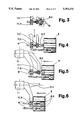
- FIG. 3 is a sectional view of a gripper pairs and centering module with a first phase of gripping a contact part
- FIG. 4 is a view of the embodiment of FIG. 3 in a second phase
- FIG. 5 is a view of the embodiment of FIG. 3 in a third phase
- FIG. 6 is a view of the embodiment of FIG. 3 in a fourth phase.
- a method for the automatic mounting of electric conductors 8 with contact parts 8.1, 8.2 in connector shells 5 with a gripper system includes the following process steps: At a gripper tool 4, supported by a robot gripper 3, grips at least one connector shell 5 from a connector-shell magazine 7.1, 7.2, 7.3.
- the two contact parts 8.1, 8.2 of the electric conductors 8 are centered at the end of a cable-processing line 9 and are maintained in a rest position at a contact part 8.1, 8.2 and at the insulated conductor 8 by respectively two gripper pairs 11.1, 11.2 of a double gripper 11.
- At least one robot gripper 3 moves in the direction of a contact part 8.1, 8.2 of the electric conductor 8 and shifts a connector shell 5 with one of its recesses to align at a contact part 8.1, 8.2 of the electric conductor 8.
- a outer gripper pair 11.1 of the double gripper 11 gripping at the contact part 8.1, 8.2 of the electric conductor 8 opens itself.
- the robot gripper 3 shifts the connector shell 5 fully onto the contact part 8.1, 8.2 of the electric conductor 8.
- a inner gripper pair 11.2 of the double gripper 11 opens.
- the robot gripper 3 carries out with the inserted electric conductor or conductors a strip-off motion below a fixed separating element 18.
- the slide-on process of a connector shell 5 at the contact part 8.1, 8.2 of the electric conductor 8 can be repeated upon a surpassing of a preset put-on force after a return motion of the robot gripper 3.
- the electric conductor 8 can be eliminated after a futile repeating of the slide-on process.
- the robot gripper 3 can perform a motion opposite to the shift-in direction for testing the assembly process of the connector shell 5 on the contact part 8.1, 8.2 of the electric conductor 8.
- the double gripper 11 can be rotated by half a rotation around its longitudinal axis for plugging together the second contact part 8.2 of the electric conductor 8 with connector shells 5.
- the finished equipped cable harness 13 can be bound off.
- the cable harness 13 can be electrically tested.
- the present invention provides furthermore for an apparatus for the automatic mounting of electric conductors 8 with contact parts 8.1, 8.2 in connector shells 5 by a gripper system.
- a centering device is disposed at the end of a cable-processing line 9 for the contact parts 8.1, 8.2 of the electric conductors 8.
- a double gripper 11 of a rotatable transfer module 10 grips one of the two contact parts 8.1, 8.2 of the electric conductor 8, respectively at the contact part and at the insulated conductor.
- the gripper tool 4 grips at least one connector shell 5.
- All gripper pairs 11.1, 11.2, the two outer gripper pairs 11.1 as well as the two inner gripper pairs 11.2, of the double gripper 11 can be movable and controllable independent of each other.
- the repetition of the shift-in process of a connector shell 5 onto the contact part 8.1, 8.2 of the electric conductor 8 can be initiated by a sensor disposed at the robot gripper 3 upon surpassing of a preset insertion force.
- a sensor can be disposed at the gripper 3, which sensor can survey after termination of the assembly process the withdrawal force of the motion opposite to the insertion direction.
- a robot gripper 3 can extend the finished equipped cable harness 13.
- a transport device 14 can be provided for receiving the cable harness 13 in an extended state.
- a binding device 17 can be disposed between the industrial robot 1 and the transport device 14.
- An electric testing device for the cable harnesses 13 can be disposed between the industrial robot 1 and the transport device 14.
- An industrial robot is designated with the reference numeral 1 in FIGS. 1 and 2.
- the industrial robot 1 exhibits a gripper arm 2 and a gripper 3.
- Different gripper tools 4 for a connector shell 5 or for several equal or different connector shells 5 are grippable with the gripper 3.
- the gripper tools 4 are disposed in a tool magazine 6 in the region of the gripper arm 2.
- the connector shells 5, which are stored and ready supported in parallel adjacent connector-shell magazines 7, 7.1, 7.2, 7.3, are automatically replaced at each withdrawal. Simultaneously, several connector shells 5 can be received by the robot gripper 3 of the industrial robot 1 with the aid of the gripper tool 4.
- the contact parts 8.1, 8.2 of an electric conductor 8 are prepared in a processing line 9, not belonging to the subject-matter of the invention.
- the contact parts 8.1, 8.2 of the electric conductor 8 are moved forward in clock cycles by individual transfer modules 10.
- the two contact parts 8.1, 8.2 of the electric conductor 8 are received by a double gripper 11 at the end of a processing line 9 and are maintained in a rest position for further processing.
- the double gripper 11 comprises two outer gripper pairs 11.1 and two inner gripper pairs 11.2. All gripper pairs 11.1, 11.2 are movable and controllable independent of each other.
- the outer gripper pair 11.1 grips a prepared contact part 8.1, 8.2 of the electric conductor 8 such that the corresponding recess of the connector shell 5 and a contact part 8.1, 8.2 of the electric conductor 8 can be assembled and joined.
- the outer gripper pair 11.1 thus grips in the rear region of the insulation crimp, while the inner gripper pair 11.2 grips further in the rear, in the region of the insulation of the electric conductor 8.
- a fixed separating element 18 is disposed below the double gripper 11, which strips, by a motion of the robot gripper 3, the mounted electric conductors 8.
- the transport device 14 can comprise respectively two endless rubber-band pairs 15, 16, which can be moved apart and which, in each case, are disposed parallel and on top of each other.
- the rubber bands, disposed on top of each other, are driven with a different direction of rotation.
- the cable harnesses 13 are, preferably in a stretched state, clamped and carried along between the two center rubber belt strands running in the same direction.
- At least one binding device 17 for the binding of the finished cable harnesses can be placed at the beginning of the transport device.
- the above-described device operates as follows:
- the contact parts 8.1, 8.2 of electric conductors 8 for the production of cable harnesses 13 are prepared on the processing line 9 of an independent cable-processing station.
- the contact parts 8.1, 8.2 of the electric conductors are brought into a desired position by a conventional centering module 19, such as for example taught in European Patent EP-A-0,041,332, at the end of the processing line 9, and the contact parts 8.1, 8.2 are received by the rotary transfer module 10 with the double grippers 11 for the production of cable harnesses 13.
- the prepared contact part 8.1, 8.2 is thereby maintained in a rest position, in each case, by an outer gripper pair 11.1 of the double gripper 11 in the region of the insulation crimp and, in each case, by an inner gripper pair 11.2 somewhat further inside, in the region of the insulation of the electric conductor 8.
- the device placed outside of the cable processing station for the automatic mounting of the electric conductors 8 and of the connector shells 5 is prepared in the meantime for the equipping of the connector shells 5.
- the robot gripper 3 of the industrial robot 1 can grip the corresponding gripping tool 4 for the receiving of the desired connector shell 5 for the intended cable-harness production from the tool magazine 6, or, since the gripper tool has to be exchanged only upon full program changes and thus relatively rarely, the gripper tool 4 is positioned manually at the robot gripper 3.
- the gripper arm 2 of the industrial robot 1 pivots to the side of the parallel disposed connector-shell magazine 7.1, 7.2, 7.3, and the gripper tool 4 grips the predetermined number of connector shells 5.
- the connector shells 5, removed from the connector-shell magazines 7.1, 7.2, 7.3, are replaced by connector shells 5 automatically pushed in from behind.
- the gripper arm 2 is shifted with the gripped connector shells 5 in front of the first contact part 8.1 of the electric conductor 8, supported by the double gripper 11.
- the axis of the predetermined recess of the connector shell 5 is aligned with the axis of the supported contact part 8.1 of the electric conductor 8.
- the robot gripper 3 now shifts itself with the gripper tool 4 and the connector shells 5 in the axial direction toward the contact part 8.1 of the electric conductor 8, until the contact part 8.1 of the electric conductor engages in the recess of the connector shell 5.
- the one outer gripper pair 11.1 of the double gripper 11 opens up and frees the path in order for the connector shell 5 to be fully slid onto the contact part 8.1.
- the other contact part 8.2 of the electric conductor 8 can simultaneously be equipped, with the aid of a second industrial robot 1, with a connector shell 5, or the electric conductor 8 is rotated by 180 degrees in a horizontal plane with the aid of the rotation module 10 following to the equipping of the first contact part 8.1, whereby the second contact part 8.2, for example, is equipped with a second connector shell 5 of the same industrial robot 1.
- the gripper moves with the connector shells such that the electric conductor 8 of the just mounted contact part, possibly together with all remaining already mounted electric conductors 8, is deflected by the fixedly disposed separating element 18, in order to provide the necessary free space for the mounting and assembly of further contact parts 8.1, 8.2 of electric conductors 8.
- the contact part 8.2 of a completely fabricated electric conductor 8 is shown in FIG. 3 in a first phase.
- the contact part 8.2 is gripped by the gripper pairs 11.1 and 11.2 of the double gripper 11.
- the centering module 19 serves for a precise alignment of the contact part 8.2 of the electric conductor 8 of the crimp contact.
- the centering module 19 can be of conventional construction such as is taught, for example, in the European Patent Document EP-A-0,041,332, where a terminal positioner 75 with arms 78 and recesses 79 is illustrated in FIGS. 7, 8, and 10 of this reference.
- a connector shell 5 is fed in and is furnished with a first, already mounted electric conductor 8.
- the connector shell 5 is mounted to the crimping contact, where both gripper pairs 11.1 and 11.2 of the double gripper 11 are closed.
- the finished cable harness 13 can now, for example according to FIG. 1, be placed by a gripper arm 2 into a discharge bin 12, for example a tub, or, according to FIG. 2, be transferred to a transport device 14, where the finished equipped cable harness 13, in this case, is placed by the two industrial robots 1, with the aid of the gripped connector shells 5, with preferably extended electric conductors 8, between the two center belt strands of the rubber bands of the transport device 14.
- the two belt strands running in the same direction, grip the cable harness 13 and transport it to a collection location.
- the horizontal distance between the two rubber-band pairs 15, 16, disposed above each other, can be set in advance, depending on the length of the electric conductors 8.
- a binding device 17 can be controlled ahead of the transfer of the cable harness from the industrial robot 1 to the transport device 14.
- the binding device 17 can cleanly bind the stretched section of the cable harness 13 at desired locations. It is also possible, in order to release the industrial robot for other manipulations or shorter clock cycle times at a higher frequency, to provide an additional device in front of the transport device, which receives the cable harness from the robot in order to perform further operations without clock cycle time losses for the robot, such as, for example, for an overall electric testing, for labelling of connector shells, or for the closing of protective covers belonging to the connector shells. The same additional device would then also be responsible for the subsequent transfer of the cable harnesses to the transport device.
- a centered contact 8.1, 8.2 of the electric conductor 8, properly gripped by the double gripper 11 exhibits deficiencies which prevent a proper mounting of a connector shell 5 to the contact part 8.1, 8.2, for example, when parts of a damaged contact part protrude and are exposed or unconnected at the body of the connector shell 5. Interferences of this kind are excluded by a surveillance of the mounting force by a sensor, not illustrated and disposed at the robot gripper 3. Upon surpassing of a predetermined force, and before a further damaging occurs, a return motion of the robot gripper 3 and a renewed mounting attempt is initiated. If also the second, or possibly, the third mounting attempt fails, the defective electric conductor 8 is rejected and eliminated.
- each individual connected conductor 8 is subjected to a likewise predetermined tension force. If the tension force is not reached during the pull-off test, this means a bad contact seat and the tested electric conductor 8, possibly with already connected additional connections, is also eliminated.
- a cross transport band or only a collection bin could be disposed below the assembled device for the removal of possibly eliminated defective cable harness parts.
Landscapes
- Engineering & Computer Science (AREA)
- Manufacturing & Machinery (AREA)
- Manufacturing Of Electrical Connectors (AREA)
- Manipulator (AREA)
Applications Claiming Priority (2)
| Application Number | Priority Date | Filing Date | Title |
|---|---|---|---|
| CH252488 | 1988-07-01 | ||
| CH02524/88 | 1988-07-01 |
Related Child Applications (1)
| Application Number | Title | Priority Date | Filing Date |
|---|---|---|---|
| US07/572,000 Continuation-In-Part US5157830A (en) | 1988-07-01 | 1990-08-23 | Method for automatically connecting electric conductors with contact parts to connector shells |
Publications (1)
| Publication Number | Publication Date |
|---|---|
| US5083370A true US5083370A (en) | 1992-01-28 |
Family
ID=4235732
Family Applications (1)
| Application Number | Title | Priority Date | Filing Date |
|---|---|---|---|
| US07/374,271 Expired - Lifetime US5083370A (en) | 1988-07-01 | 1989-06-30 | Method for automatically connecting electrical conductors to contact parts in plug housings |
Country Status (5)
| Country | Link |
|---|---|
| US (1) | US5083370A (de) |
| EP (1) | EP0348615B1 (de) |
| JP (1) | JP2792917B2 (de) |
| DE (1) | DE58907877D1 (de) |
| ES (1) | ES2057001T3 (de) |
Cited By (17)
| Publication number | Priority date | Publication date | Assignee | Title |
|---|---|---|---|---|
| US5168611A (en) * | 1991-05-30 | 1992-12-08 | Amp Incorporated | Automated lead making machine having defective lead removal |
| US5168613A (en) * | 1991-09-20 | 1992-12-08 | Amp Incorporated | Controllable door for defective lead removal |
| US5548892A (en) * | 1995-01-19 | 1996-08-27 | The Whitaker Corporation | Machine for assembling an insulation displacement connector and terminating a conductor thereto |
| US5704110A (en) * | 1995-11-02 | 1998-01-06 | Carl Freudenberg | Device for crimping a plastically deforming metal pole shoe around the end of a cable |
| US5718042A (en) * | 1995-11-07 | 1998-02-17 | Yazaki Corporation | Terminal insertion method |
| US5745991A (en) * | 1994-06-15 | 1998-05-05 | The Whitaker Corporation | Machine and method for producing electrical harness |
| US5774981A (en) * | 1995-07-11 | 1998-07-07 | Yazaki Corporation | Terminal insertion method and apparatus |
| US20020076990A1 (en) * | 2000-12-15 | 2002-06-20 | Sumitomo Wiring Systems Ltd. | Apparatus for processing a stacked-type connector of a wire harness, a housing holder, apparatus and method and for stacking housings of a stacked-type connectors, and apparatus for pressing a joint portion of stacked-type connector |
| US20030066190A1 (en) * | 2001-10-05 | 2003-04-10 | Jean Revel | Method and equipment for equipping plug housings with fitted-out cable ends of a cable |
| US20030140492A1 (en) * | 2000-02-23 | 2003-07-31 | Venrooij Johannes Lambertus Geradus Maria | Apparatus and method for processing electronic components |
| US6655025B2 (en) * | 2000-05-31 | 2003-12-02 | Yazaki Corporation | Connector and locking fixture thereof |
| US20040143966A1 (en) * | 2001-04-10 | 2004-07-29 | Louis Soriano | Method and apparatus for equipping plug housings with fitted-out cable ends of a cable |
| US20090199396A1 (en) * | 2008-02-09 | 2009-08-13 | Cirris Systems Corporation | Apparatus for electrical pin installation and retention confirmation |
| DE102018110268B3 (de) | 2018-04-27 | 2019-08-01 | Kromberg & Schubert Gmbh & Co. Kg | Greifvorrichtung und Verfahren zum automatisierten Montieren und Einstecken |
| US10723584B2 (en) | 2016-10-03 | 2020-07-28 | Komax Holding Ag | Method and device for aligning prefabricated cable ends of a cable harness in correct rotational position |
| US10804668B2 (en) | 2016-10-03 | 2020-10-13 | Komax Holding Ag | Device for assembling a plug housing |
| US11340575B2 (en) * | 2017-03-15 | 2022-05-24 | The Boeing Company | Apparatus, system, and method for picking, placing, and melting solder sleeves onto shielded electrical wires and cables |
Families Citing this family (9)
| Publication number | Priority date | Publication date | Assignee | Title |
|---|---|---|---|---|
| DE4002193C2 (de) * | 1990-01-25 | 1993-10-07 | Grote & Hartmann | Verfahren zum Bestücken der Gehäusekammern von Gehäusen mit an elektrische Leitungen gecrimten Kontaktelementen sowie Zusatzvorrichtung zur Durchführung des Verfahrens für eine Kontaktelemente an elektrische Leitungen crimpende Grundmaschine |
| EP0440955B1 (de) * | 1990-02-06 | 1995-03-15 | Ttc Technology Trading Company | Einrichtung zum automatischen Montieren von elektrischen Leitern mit Kontaktteilen in Steckergehäuse |
| JPH0736352B2 (ja) * | 1990-03-23 | 1995-04-19 | 住友電装株式会社 | 電線付端子のコネクタハウジングへの挿入方法および装置 |
| JP2985624B2 (ja) * | 1993-12-21 | 1999-12-06 | 住友電装株式会社 | 端子付き電線の挿入駆動装置 |
| US5537741A (en) * | 1995-02-01 | 1996-07-23 | Alcoa Fujikura Limited | Method of wire harness assembly system |
| CN102035122B (zh) * | 2010-10-21 | 2015-07-15 | 昆山德力康电子科技有限公司 | 一种连接器的组装设备 |
| EP2958201A1 (de) | 2014-06-16 | 2015-12-23 | Delphi Technologies, Inc. | Vorrichtung und Verfahren zum automatischen Bestücken eines Steckergehäuses |
| DE102019119468A1 (de) * | 2019-04-24 | 2020-10-29 | Metzner Maschinenbau Gmbh | Verfahren, Vorrichtung und System zur Konfektionierung eines elektrischen Kabels |
| CH719391A1 (de) * | 2022-01-28 | 2023-08-15 | Emmi Schweiz Ag | Schneid- und form-anlage. |
Citations (12)
| Publication number | Priority date | Publication date | Assignee | Title |
|---|---|---|---|---|
| US3964147A (en) * | 1975-01-02 | 1976-06-22 | Molex Incorporated | Connector assembly machine |
| US4074424A (en) * | 1977-03-01 | 1978-02-21 | Molex Incorporated | Crimping and wire lead insertion machine |
| US4087908A (en) * | 1976-02-18 | 1978-05-09 | Molex Incorporated | Connector harness assembly machine |
| GB2003759A (en) * | 1977-09-08 | 1979-03-21 | Grote & Hartmann | Method and apparatus for automatically inserting electrical connectors into housings |
| US4164065A (en) * | 1978-03-13 | 1979-08-14 | Molex Incorporated | Crimping and wire lead insertion machine having improved insertion means |
| EP0050422A1 (de) * | 1980-10-07 | 1982-04-28 | AMP INCORPORATED (a New Jersey corporation) | Verfahren und Apparat zum Herstellen modularer elektrischer Kabelbäume, einschliesslich Drahthaltekopf |
| US4375229A (en) * | 1979-04-28 | 1983-03-01 | Yazaki Corporation | Method and apparatus of automatically positioning wire ends for multi-mode end processing |
| US4426772A (en) * | 1981-02-19 | 1984-01-24 | Burndy Corporation | Apparatus for installing terminals on wires and insulation pods on terminals |
| US4521946A (en) * | 1982-03-31 | 1985-06-11 | Artos Engineering Company | Cutter and belt type conveyor for wire segments |
| US4557045A (en) * | 1984-12-04 | 1985-12-10 | Amp Incorporated | Insulating sleeve applying apparatus |
| US4653187A (en) * | 1985-10-31 | 1987-03-31 | Molex Incorporated | Connector fabrication method and apparatus |
| US4658503A (en) * | 1984-09-04 | 1987-04-21 | Mts Vektronics Corporation | Method and apparatus for terminal insertion |
Family Cites Families (3)
| Publication number | Priority date | Publication date | Assignee | Title |
|---|---|---|---|---|
| EP0041332A2 (de) * | 1980-06-03 | 1981-12-09 | AMP INCORPORATED (a New Jersey corporation) | Verfahren und Vorrichtung zum Einsetzen von elektrischen Endkontakten in Gehäuse von elektrischen Steckverbindern |
| JPS60130078A (ja) * | 1983-12-16 | 1985-07-11 | 矢崎総業株式会社 | コネクタハウジングへの電線付端子插入確認装置 |
| EP0272395B1 (de) * | 1986-12-23 | 1992-05-20 | Komax Ag | Transportvorrichtung für elektrische Kabel |
-
1989
- 1989-04-17 DE DE58907877T patent/DE58907877D1/de not_active Expired - Fee Related
- 1989-04-17 EP EP89106835A patent/EP0348615B1/de not_active Expired - Lifetime
- 1989-04-17 ES ES89106835T patent/ES2057001T3/es not_active Expired - Lifetime
- 1989-06-29 JP JP1168251A patent/JP2792917B2/ja not_active Expired - Fee Related
- 1989-06-30 US US07/374,271 patent/US5083370A/en not_active Expired - Lifetime
Patent Citations (12)
| Publication number | Priority date | Publication date | Assignee | Title |
|---|---|---|---|---|
| US3964147A (en) * | 1975-01-02 | 1976-06-22 | Molex Incorporated | Connector assembly machine |
| US4087908A (en) * | 1976-02-18 | 1978-05-09 | Molex Incorporated | Connector harness assembly machine |
| US4074424A (en) * | 1977-03-01 | 1978-02-21 | Molex Incorporated | Crimping and wire lead insertion machine |
| GB2003759A (en) * | 1977-09-08 | 1979-03-21 | Grote & Hartmann | Method and apparatus for automatically inserting electrical connectors into housings |
| US4164065A (en) * | 1978-03-13 | 1979-08-14 | Molex Incorporated | Crimping and wire lead insertion machine having improved insertion means |
| US4375229A (en) * | 1979-04-28 | 1983-03-01 | Yazaki Corporation | Method and apparatus of automatically positioning wire ends for multi-mode end processing |
| EP0050422A1 (de) * | 1980-10-07 | 1982-04-28 | AMP INCORPORATED (a New Jersey corporation) | Verfahren und Apparat zum Herstellen modularer elektrischer Kabelbäume, einschliesslich Drahthaltekopf |
| US4426772A (en) * | 1981-02-19 | 1984-01-24 | Burndy Corporation | Apparatus for installing terminals on wires and insulation pods on terminals |
| US4521946A (en) * | 1982-03-31 | 1985-06-11 | Artos Engineering Company | Cutter and belt type conveyor for wire segments |
| US4658503A (en) * | 1984-09-04 | 1987-04-21 | Mts Vektronics Corporation | Method and apparatus for terminal insertion |
| US4557045A (en) * | 1984-12-04 | 1985-12-10 | Amp Incorporated | Insulating sleeve applying apparatus |
| US4653187A (en) * | 1985-10-31 | 1987-03-31 | Molex Incorporated | Connector fabrication method and apparatus |
Cited By (26)
| Publication number | Priority date | Publication date | Assignee | Title |
|---|---|---|---|---|
| US5168611A (en) * | 1991-05-30 | 1992-12-08 | Amp Incorporated | Automated lead making machine having defective lead removal |
| US5168613A (en) * | 1991-09-20 | 1992-12-08 | Amp Incorporated | Controllable door for defective lead removal |
| US5745991A (en) * | 1994-06-15 | 1998-05-05 | The Whitaker Corporation | Machine and method for producing electrical harness |
| US5548892A (en) * | 1995-01-19 | 1996-08-27 | The Whitaker Corporation | Machine for assembling an insulation displacement connector and terminating a conductor thereto |
| US5774981A (en) * | 1995-07-11 | 1998-07-07 | Yazaki Corporation | Terminal insertion method and apparatus |
| US5704110A (en) * | 1995-11-02 | 1998-01-06 | Carl Freudenberg | Device for crimping a plastically deforming metal pole shoe around the end of a cable |
| US5718042A (en) * | 1995-11-07 | 1998-02-17 | Yazaki Corporation | Terminal insertion method |
| US20030140492A1 (en) * | 2000-02-23 | 2003-07-31 | Venrooij Johannes Lambertus Geradus Maria | Apparatus and method for processing electronic components |
| US6655025B2 (en) * | 2000-05-31 | 2003-12-02 | Yazaki Corporation | Connector and locking fixture thereof |
| US20020076990A1 (en) * | 2000-12-15 | 2002-06-20 | Sumitomo Wiring Systems Ltd. | Apparatus for processing a stacked-type connector of a wire harness, a housing holder, apparatus and method and for stacking housings of a stacked-type connectors, and apparatus for pressing a joint portion of stacked-type connector |
| US7024760B2 (en) * | 2001-04-10 | 2006-04-11 | Komax Holding Ag | Method and apparatus for equipping plug housings with fitted-out cable ends of a cable |
| US20040143966A1 (en) * | 2001-04-10 | 2004-07-29 | Louis Soriano | Method and apparatus for equipping plug housings with fitted-out cable ends of a cable |
| US6842975B2 (en) * | 2001-10-05 | 2005-01-18 | Komax Holding Ag | Method and equipment for equipping plug housings with fitted-out cable ends of a cable |
| US20030066190A1 (en) * | 2001-10-05 | 2003-04-10 | Jean Revel | Method and equipment for equipping plug housings with fitted-out cable ends of a cable |
| US7243415B2 (en) | 2001-10-05 | 2007-07-17 | Komax Holding Ag | Equipment for equipping plug housings with fitted-out cable ends of a cable |
| US20050055826A1 (en) * | 2001-10-05 | 2005-03-17 | Jean Revel | Equipment for equipping plug housings with fitted-out cable ends of a cable |
| US20090199396A1 (en) * | 2008-02-09 | 2009-08-13 | Cirris Systems Corporation | Apparatus for electrical pin installation and retention confirmation |
| US8099857B2 (en) | 2008-02-09 | 2012-01-24 | Cirris Systems Corporation | Apparatus for electrical pin installation and retention confirmation |
| US8601675B2 (en) | 2008-02-09 | 2013-12-10 | Cirris Systems Corporation | Apparatus for electrical pin installation and retention confirmation |
| US10804668B2 (en) | 2016-10-03 | 2020-10-13 | Komax Holding Ag | Device for assembling a plug housing |
| US10723584B2 (en) | 2016-10-03 | 2020-07-28 | Komax Holding Ag | Method and device for aligning prefabricated cable ends of a cable harness in correct rotational position |
| US11340575B2 (en) * | 2017-03-15 | 2022-05-24 | The Boeing Company | Apparatus, system, and method for picking, placing, and melting solder sleeves onto shielded electrical wires and cables |
| DE102018110268B3 (de) | 2018-04-27 | 2019-08-01 | Kromberg & Schubert Gmbh & Co. Kg | Greifvorrichtung und Verfahren zum automatisierten Montieren und Einstecken |
| CN111556801A (zh) * | 2018-04-27 | 2020-08-18 | 克龙贝格和舒伯特汽车有限公司 | 用于将连接芯线的接触元件自动装配和插入触点载体中的抓取装置 |
| WO2019206621A1 (de) * | 2018-04-27 | 2019-10-31 | Kromberg & Schubert Gmbh & Co. Kg | Greifvorrichtung zum automatisierten montieren und einstecken von einem mit einer ader verbundenen kontaktelement in einen kontaktträger |
| CN111556801B (zh) * | 2018-04-27 | 2023-04-11 | 克龙贝格和舒伯特汽车有限公司 | 用于将连接芯线的接触元件自动装配和插入触点载体中的抓取装置 |
Also Published As
| Publication number | Publication date |
|---|---|
| EP0348615A1 (de) | 1990-01-03 |
| JP2792917B2 (ja) | 1998-09-03 |
| JPH0254884A (ja) | 1990-02-23 |
| DE58907877D1 (de) | 1994-07-21 |
| ES2057001T3 (es) | 1994-10-16 |
| EP0348615B1 (de) | 1994-06-15 |
Similar Documents
| Publication | Publication Date | Title |
|---|---|---|
| US5083370A (en) | Method for automatically connecting electrical conductors to contact parts in plug housings | |
| US5157830A (en) | Method for automatically connecting electric conductors with contact parts to connector shells | |
| EP0481769B1 (de) | Verfahren und Gerät zum Wickeln und Beenden des Leiters einer Statorspule | |
| JP3076079B2 (ja) | 接触部品を備えた電気導体をコネクタシェルに自動的に接続するための装置及び方法 | |
| CA1049236A (en) | Arranging randomly positioned articles into preselected positions | |
| JP2706408B2 (ja) | 端子挿入装置 | |
| US7024760B2 (en) | Method and apparatus for equipping plug housings with fitted-out cable ends of a cable | |
| EP3333987B1 (de) | Palette zum transport von elektrischen verbindern und methode zum stecken von elektrischen steckverbindern unter verwendung der gleichen | |
| EP0040491B1 (de) | Vorrichtung zum Einstecken elektrischer Steckkontakte in das Gehäuse eines elektrischen Steckers | |
| GB2092029A (en) | Apparatus and method for connecting the ends of stator windings to their terminals | |
| US4680841A (en) | Electrical harness fabrication apparatus | |
| CN107565301B (zh) | 用于焊接包含若干单独导线的线束的设备和方法 | |
| EP0614252B1 (de) | Zufuhrmechanismus für Verbindergehäuse | |
| EP0041332A2 (de) | Verfahren und Vorrichtung zum Einsetzen von elektrischen Endkontakten in Gehäuse von elektrischen Steckverbindern | |
| US4411608A (en) | Automatic apparatus for transferring electrical cords with terminal blades and for the testing thereof | |
| US4779334A (en) | Apparatus for inserting terminals on the ends of wires into cavities in an electrical connector | |
| US5575060A (en) | Terminal inserting drive apparatus for inserting terminals on wire | |
| EP0881720B1 (de) | Gerät zum Anbringen eines Leitungsdurchführungspfropfens | |
| EP1775804B1 (de) | Vorrichtung zur Herstellung von einer elektrischen Verdrahtung | |
| US5305508A (en) | Cable-bundling equipment for cable-processing machines | |
| CN115939903A (zh) | 网络连接器生产线 | |
| JP3764630B2 (ja) | コネクタ導通検査装置及びコネクタ導通検査方法 | |
| US5402566A (en) | Method and machine for attaching an electrical connector to a coaxial cable | |
| KR20250155563A (ko) | 자동 압착기용 공급 장치, 자동 압착기, 컨베이어 벨트 및 벨트 시스템, 공급 시스템, 자동 압착기의 작동 방법, 하이브리드 플러그인 커넥터와 이를 위한 장착 방법 | |
| EP1113539A2 (de) | Prozess zum Erkennen und/oder Anschliessen von Drähten eines Kabels |
Legal Events
| Date | Code | Title | Description |
|---|---|---|---|
| AS | Assignment |
Owner name: KOMAX AG, SWITZERLAND Free format text: ASSIGNMENT OF ASSIGNORS INTEREST.;ASSIGNORS:KOCH, MAX;LUSTENBERGER, ALOIS;REEL/FRAME:005097/0685 Effective date: 19890623 |
|
| STCF | Information on status: patent grant |
Free format text: PATENTED CASE |
|
| AS | Assignment |
Owner name: TTC TECHNOLOGY TRADING COMPANY, SWITZERLAND Free format text: ASSIGNMENT OF ASSIGNORS INTEREST.;ASSIGNOR:KOMAX AG;REEL/FRAME:006002/0494 Effective date: 19920107 |
|
| FEPP | Fee payment procedure |
Free format text: PAYOR NUMBER ASSIGNED (ORIGINAL EVENT CODE: ASPN); ENTITY STATUS OF PATENT OWNER: SMALL ENTITY |
|
| FPAY | Fee payment |
Year of fee payment: 4 |
|
| FEPP | Fee payment procedure |
Free format text: PAYER NUMBER DE-ASSIGNED (ORIGINAL EVENT CODE: RMPN); ENTITY STATUS OF PATENT OWNER: SMALL ENTITY |
|
| FEPP | Fee payment procedure |
Free format text: PAYOR NUMBER ASSIGNED (ORIGINAL EVENT CODE: ASPN); ENTITY STATUS OF PATENT OWNER: SMALL ENTITY |
|
| FPAY | Fee payment |
Year of fee payment: 8 |
|
| FPAY | Fee payment |
Year of fee payment: 12 |