US4964703A - Image-forming lens - Google Patents
Image-forming lens Download PDFInfo
- Publication number
- US4964703A US4964703A US07/358,497 US35849789A US4964703A US 4964703 A US4964703 A US 4964703A US 35849789 A US35849789 A US 35849789A US 4964703 A US4964703 A US 4964703A
- Authority
- US
- United States
- Prior art keywords
- lens
- refractive index
- index distribution
- point
- vicinity
- Prior art date
- Legal status (The legal status is an assumption and is not a legal conclusion. Google has not performed a legal analysis and makes no representation as to the accuracy of the status listed.)
- Expired - Lifetime
Links
Images


Classifications
-
- G—PHYSICS
- G02—OPTICS
- G02B—OPTICAL ELEMENTS, SYSTEMS OR APPARATUS
- G02B13/00—Optical objectives specially designed for the purposes specified below
- G02B13/0095—Relay lenses or rod lenses
-
- G—PHYSICS
- G02—OPTICS
- G02B—OPTICAL ELEMENTS, SYSTEMS OR APPARATUS
- G02B3/00—Simple or compound lenses
Definitions
- This invention relates to an image-forming lens such as an objective or collimator lens which is used in a video disk, audio disk or optical memory apparatus, and more particularly to a distributed index image-forming lens for an optical memory which has a numerical aperture NA of not more than about 0.5 and the aberration of which in the vicinity of the optical axis is preferably corrected.
- the distributions of the refractive indexes of distributed index lenses are classified into three fundamental refractive index distributions: radial, axial and spherical types.
- the radial type is defined by a refractive index distribution which is aligned in the radial direction perpendicular to the optical axis;
- the axial type is defined by a refractive index distribution which is aligned in the direction of the optical axis;
- the spherical type has a refractive index distribution which exhibits a spherical symmetry about a point.
- the present invention is designed to solve the above-described problems. It is therefore an object of the present invention to provide an image-forming lens that has a simple construction and a spherical refractive index distribution in which, when the numerical aperture is not more than 0.5, spherical aberration can be corrected while satisfying the sine condition.
- the present invention provides an image-forming lens in the form of a plano-convex lens in which a surface ⁇ 1 on the object side is a spherical surface and a surface ⁇ 2 on the image side is a plane surface.
- the image-forming lens has a refractive index distribution N( ⁇ ) exhibiting a substantially spherical symmetry with its center located in the vicinity of the highest point of the object-side surface
- N( ⁇ ) N 0 +N 1 ⁇ 2 +N 2 ⁇ 4 + . . . . .
- N 0 , N 1 , N 2 . . . are refractive index distribution coefficients
- f is the focal length of the lens
- d is the axial thickness of the lens
- ⁇ is the distance from the highest point of the object-side surface ⁇ 1 .
- the relationship is obtained if it is assumed that the highest point of the object-side surface ⁇ 1 corresponds to the origin (0, 0, 0) of a three-dimensional coordinate system; and the optical axis, meridional direction, and sagittal direction correspond to the X, Y and Z axes, respectively.
- the term "highest point” shall mean that point on the spherical surface ⁇ 1 which is most distant from the plane surface ⁇ 2 when measured perpendicularly from the plane surface ⁇ 2 .
- the recording surface is covered and protected by a cover glass.
- the image-forming lens in accordance with the present invention is designed to take into consideration the thickness t of this cover substrate, it is preferable in selecting the system specifications to set the relationship between the focal length f of the image-forming lens and the thickness t of the cover substrate so that the following inequality is satisfied:
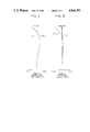
- FIG. 1 is a cross-sectional view of an image-forming lens according to the present invention.
- FIGS. 2 to 5 are graphs of the aberrations of image-forming lenses which are first to fourth examples of the design of the invention.
- FIG. 1 is a cross-sectional view through an image-forming lens L in accordance with the present invention and a transparent cover substrate P, for example, of an optical disk or card.
- the image-forming lens L has a primary surface ⁇ 1 , a secondary surface ⁇ 2 , a thickness d at the axis of the lens L, and a highest point 0 on the primary surface ⁇ 1 .
- the cover substrate P has a thickness t.
- An arrow indicates the distance from the highest point 0.
- the curvature of the secondary surface ⁇ 2 in accordance with the present invention is zero (radius of curvature: ⁇ ), that is, the secondary surface ⁇ 2 is a flat plane.
- the present invention specifies that the primary surface ⁇ 1 is provided on the object side and the secondary surface ⁇ 2 is provided on the image side, when the lens is used to provide negative magnification. Accordingly, when the lens is used as an objective lens for recording on an optical memory such as an optical disk or card, the surface of the lens which faces the recording surface is the secondary surface, as shown in FIG. 1; and when the lens is used as a collimator lens for a semiconductor laser or the like, the surface of the lens which faces the light source is the secondary surface.
- the cover substrate P disposed on the image surface side may be, for example, a protective substrate of a recording medium for optical disks, or may be the beam-issuing aperture of a semiconductor laser.
- an image is formed on one surface of the parallel-plane plate, namely, the cover substrate P, opposite to the other surface thereof facing the lens L.
- this parallel-plane plate may be disposed in the vicinity of the lens or be connected thereto, when the lens is used as a collimator lens.
- Formula (1) represents a spherical refractive index distribution in general.
- Inequality (2) above indicates the condition of a refractive index N 0 at the center of the refractive index distribution in accordance with the present invention, namely the refractive index defined in the vicinity of the highest point of the primary surface ⁇ 1 .
- This inequality is determined by a condition which corrects the spherical aberration and the sine condition when the secondary surface ⁇ 2 is assumed to be a flat plane.
- the sine condition is a condition of constant aberration in the vicinity of image points on the axis. To satisfy this condition, it is necessary to eliminate the coma in the vicinity of image points on the axis over the entire luminous flux.
- the offence of sine condition which is described below, represents the amount of deviation from the sine condition, in other word, it is a quantity which represents the occurrence of the coma in the vicinity of image points on the axis. That is, if N 0 is smaller than the lower limit value in Inequality (2), the offence of sine condition (hereinafter referred to as the O.S.C.) is negative at the part thereof which is of a high order and therefore causes introverted coma. If N 0 is larger than the higher limit value, the O.S.C. is positive and hence causes extroverted coma.
- Inequality (3) indicates the condition of the thickness d on the axis of the lens and at the same time indicates a condition wherein the spherical aberration and the sine condition are corrected, along with a condition in which the edge thickness of the lens is adequately set. If d/f is smaller than the lower limit value in Inequality (3), a part of the O.S.C. is negative and the edge thickness of the lens is reduced, thus making it difficult to set NA at 0.45 to 0.5. If d/f is larger than the upper limit value, the O.S.C. is positive.
- Inequality (4) indicates the condition of a distribution coefficient N 1 which determines the basic distribution form of the refractive index distribution N ( ⁇ ). The spherical aberration and the O.S.C.
- Inequality (5) defines a condition relating to the thickness t of a parallel-plane plate such as the cover substrate P, and is determined by a thickness 1.0 to 1.5 mm for an ordinary optical disk plate, a focal length of 3 to 6 mm for an objective, a thickness of 0.5 to 1.5 mm for the emergence aperture portion of a semiconductor laser and a focal length of 8 to 16 mm for a collimator lens.
- t/f is smaller than the lower limit, the thickness of the lens is so reduced in accordance with the conditions of the aberration correction that a proper value of NA cannot be obtained. Therefore it is impossible to use the lens as an objective. If t/f is larger than the upper limit, the thickness of the lens is increased too much for an adequate movable distance and a suitable interval between the light source and the lens to be set.
- the invention can provide an image-forming lens with a simple construction including one flat surface, the NA of which is not more than 0.5 and the aberration of which is properly corrected, when the Inequalities (4) to (5) are satisfied.
- the spherical refractive index distribution in accordance with the present invention can be provided in substantially the same manner as that in the case of microlenses, such that a spherical blank undergoes ion exchange or a blank in the form of a plane plate is covered by a mask having very fine holes and thereafter undergoes processing by a field-introducing method or the like, thus forming the refractive index distribution. It is also possible to employ a suspension polymerization method made public in the 32nd Applied Physics Associated Lecture Meeting (Oyo Busturigaku Kankei Rengo Koenkai), spring 1985.
- the refractive index distribution formed in this image-forming lens can be represented by the above-mentioned formula (1) with, as a parameter, distance from the origin 0, which is assumed be the highest point 0 of the primary surface ⁇ 1 of the lens.
- This representative formula has been determined for convenience sake, and it does not exclude other forms.
- Tables 1 to 4 show lens data, refractive index distributions and items of other related data on the first to fourth examples of the image-forming lens provided in accordance with the present invention.
- f represents the focal length
- ⁇ 1 and ⁇ 2 the curvatures of the primary and secondary surfaces
- NA the numerical aperture
- d the axial thickness
- N 0 the refractive index in the vicinity of the highest point of the primary surface
- N 1 the refractive index distribution coefficient
- t the thickness of the cover substrate P
- ⁇ t the refractive index of the substrate P.
- the refractive index distribution coefficients N 2 , N 3 . . . are all set at zero.
- FIGS. 2 to 5 show the aberration diagrams of the image-forming lenses of the first to fourth examples.
- S.A. represents the spherical aberration
- O.S.C. represents the offence of sine condition.
- both the spherical aberration and the sine condition are properly corrected so as to ensure appropriate image-forming performance for this kind of lens system.
- the present invention provides the lens in the form of a plano-convex lens with a spherical refractive index distribution which can be readily manufactured with a simple construction, ensuring that any aberration in the vicinity of the axis of the lens can be properly corrected as long as the NA of the lens is not more than 0.5.
- the lens in accordance with the present invention is highly effective when used as an objective lens for an optical memory device and as a collimator lens for a semiconductor laser.
Applications Claiming Priority (2)
| Application Number | Priority Date | Filing Date | Title |
|---|---|---|---|
| JP60263078A JPS62123419A (ja) | 1985-11-22 | 1985-11-22 | 結像レンズ |
| JP60-263078 | 1985-11-22 |
Related Parent Applications (1)
| Application Number | Title | Priority Date | Filing Date |
|---|---|---|---|
| US07129368 Continuation | 1987-11-30 |
Publications (1)
| Publication Number | Publication Date |
|---|---|
| US4964703A true US4964703A (en) | 1990-10-23 |
Family
ID=17384527
Family Applications (1)
| Application Number | Title | Priority Date | Filing Date |
|---|---|---|---|
| US07/358,497 Expired - Lifetime US4964703A (en) | 1985-11-22 | 1989-05-30 | Image-forming lens |
Country Status (2)
| Country | Link |
|---|---|
| US (1) | US4964703A (ja) |
| JP (1) | JPS62123419A (ja) |
Cited By (4)
| Publication number | Priority date | Publication date | Assignee | Title |
|---|---|---|---|---|
| US5523885A (en) * | 1989-10-27 | 1996-06-04 | Olympus Optical Co., Ltd. | Viewfinder optical system |
| WO2001048549A1 (en) * | 1999-12-23 | 2001-07-05 | Alcatel | Shutter for satellite tracking antenna |
| US20010028626A1 (en) * | 2000-02-29 | 2001-10-11 | Hitachi, Ltd. | Objective lens for optical disc drive |
| US20070279766A1 (en) * | 2006-06-01 | 2007-12-06 | Tetsuro Ishizuka | Image forming lens and portable information terminal |
Citations (24)
| Publication number | Priority date | Publication date | Assignee | Title |
|---|---|---|---|---|
| US3486808A (en) * | 1966-03-14 | 1969-12-30 | Bausch & Lomb | Gradient refractive index optical lenses |
| US3626194A (en) * | 1968-08-30 | 1971-12-07 | Nippon Selfoc Co Ltd | Photoelectric converter including convergent lens with refractive index distribution |
| US3729253A (en) * | 1971-05-28 | 1973-04-24 | Western Electric Co | Optical system comprising a single element having a continuously varying index of refraction |
| US4027952A (en) * | 1974-05-14 | 1977-06-07 | U.S. Philips Corporation | Single optical lens with large aperture and large field |
| JPS556354A (en) * | 1978-06-30 | 1980-01-17 | Agency Of Ind Science & Technol | Refractive index distribution type lens |
| JPS57181516A (en) * | 1981-05-01 | 1982-11-09 | Agency Of Ind Science & Technol | Heterogeneous refractive index lens |
| JPS58122512A (ja) * | 1982-01-11 | 1983-07-21 | コ−ニング・グラス・ワ−クス | ビデオデイスクのピツクアツプレンズ等に用いられる屈折率分布形球面レンズ |
| US4415238A (en) * | 1981-07-13 | 1983-11-15 | U.S. Philips Corporation | Single lens having one spherical and one aspherical refractive surface |
| JPS58205122A (ja) * | 1982-05-26 | 1983-11-30 | Nippon Sheet Glass Co Ltd | 組合せレンズ |
| JPS5962815A (ja) * | 1982-10-04 | 1984-04-10 | Nippon Kogaku Kk <Nikon> | 屈折率分布型レンズ |
| US4449792A (en) * | 1980-10-31 | 1984-05-22 | Konishiroku Photo Industry Co., Ltd. | Large-aperture single lens with aspherical surfaces |
| JPS60140308A (ja) * | 1983-12-28 | 1985-07-25 | Canon Inc | 屈折率分布型単レンズ |
| JPS60140309A (ja) * | 1983-12-28 | 1985-07-25 | Canon Inc | 屈折率分布型単レンズ |
| JPS60159817A (ja) * | 1984-01-31 | 1985-08-21 | Canon Inc | 色収差補正方法 |
| JPS60163015A (ja) * | 1984-02-03 | 1985-08-24 | Canon Inc | 球面収差の補正方法 |
| JPS60172010A (ja) * | 1984-02-17 | 1985-09-05 | Sony Corp | 光ピツクアツプ用屈折率分布型レンズ |
| US4571034A (en) * | 1982-08-05 | 1986-02-18 | Olympus Optical Co., Ltd. | Lens system for optical recording type disks |
| US4634233A (en) * | 1983-09-02 | 1987-01-06 | Canon Kabushiki Kaisha | Method of forming a light source by the use of a refractive index distribution type lens and light source device |
| US4643535A (en) * | 1984-01-13 | 1987-02-17 | Nippon Sheet Glass Co., Ltd. | Optical information recording/reproducing element |
| US4647159A (en) * | 1984-12-26 | 1987-03-03 | Canon Kabushiki Kaisha | Gradient index type single lens |
| US4657352A (en) * | 1984-10-05 | 1987-04-14 | Canon Kabushiki Kaisha | Image optical system including a non-spherical single lens |
| US4674843A (en) * | 1985-02-22 | 1987-06-23 | Canon Kabushiki Kaisha | Gradient index lens |
| US4696552A (en) * | 1984-08-28 | 1987-09-29 | Canon Kabushiki Kaisha | Projection device with refractive index distribution type lens |
| US4721369A (en) * | 1985-09-18 | 1988-01-26 | Canon Kabushiki Kaisha | Gradient index single lens |
-
1985
- 1985-11-22 JP JP60263078A patent/JPS62123419A/ja active Pending
-
1989
- 1989-05-30 US US07/358,497 patent/US4964703A/en not_active Expired - Lifetime
Patent Citations (26)
| Publication number | Priority date | Publication date | Assignee | Title |
|---|---|---|---|---|
| US3486808A (en) * | 1966-03-14 | 1969-12-30 | Bausch & Lomb | Gradient refractive index optical lenses |
| US3626194A (en) * | 1968-08-30 | 1971-12-07 | Nippon Selfoc Co Ltd | Photoelectric converter including convergent lens with refractive index distribution |
| US3729253A (en) * | 1971-05-28 | 1973-04-24 | Western Electric Co | Optical system comprising a single element having a continuously varying index of refraction |
| US4027952A (en) * | 1974-05-14 | 1977-06-07 | U.S. Philips Corporation | Single optical lens with large aperture and large field |
| JPS556354A (en) * | 1978-06-30 | 1980-01-17 | Agency Of Ind Science & Technol | Refractive index distribution type lens |
| US4449792A (en) * | 1980-10-31 | 1984-05-22 | Konishiroku Photo Industry Co., Ltd. | Large-aperture single lens with aspherical surfaces |
| US4557566A (en) * | 1981-05-01 | 1985-12-10 | Agency Of Industrial Science & Technology | Spherical lens for spherically symmetrical graded refractive index distribution provided with rod clad |
| JPS57181516A (en) * | 1981-05-01 | 1982-11-09 | Agency Of Ind Science & Technol | Heterogeneous refractive index lens |
| US4415238A (en) * | 1981-07-13 | 1983-11-15 | U.S. Philips Corporation | Single lens having one spherical and one aspherical refractive surface |
| JPS58122512A (ja) * | 1982-01-11 | 1983-07-21 | コ−ニング・グラス・ワ−クス | ビデオデイスクのピツクアツプレンズ等に用いられる屈折率分布形球面レンズ |
| US4457590A (en) * | 1982-01-11 | 1984-07-03 | Corning Glass Works | Spherical gradient-index lens designs for video-disk pickup lens or the like |
| JPS58205122A (ja) * | 1982-05-26 | 1983-11-30 | Nippon Sheet Glass Co Ltd | 組合せレンズ |
| US4571034A (en) * | 1982-08-05 | 1986-02-18 | Olympus Optical Co., Ltd. | Lens system for optical recording type disks |
| JPS5962815A (ja) * | 1982-10-04 | 1984-04-10 | Nippon Kogaku Kk <Nikon> | 屈折率分布型レンズ |
| US4634233A (en) * | 1983-09-02 | 1987-01-06 | Canon Kabushiki Kaisha | Method of forming a light source by the use of a refractive index distribution type lens and light source device |
| JPS60140309A (ja) * | 1983-12-28 | 1985-07-25 | Canon Inc | 屈折率分布型単レンズ |
| JPS60140308A (ja) * | 1983-12-28 | 1985-07-25 | Canon Inc | 屈折率分布型単レンズ |
| US4643535A (en) * | 1984-01-13 | 1987-02-17 | Nippon Sheet Glass Co., Ltd. | Optical information recording/reproducing element |
| JPS60159817A (ja) * | 1984-01-31 | 1985-08-21 | Canon Inc | 色収差補正方法 |
| JPS60163015A (ja) * | 1984-02-03 | 1985-08-24 | Canon Inc | 球面収差の補正方法 |
| JPS60172010A (ja) * | 1984-02-17 | 1985-09-05 | Sony Corp | 光ピツクアツプ用屈折率分布型レンズ |
| US4696552A (en) * | 1984-08-28 | 1987-09-29 | Canon Kabushiki Kaisha | Projection device with refractive index distribution type lens |
| US4657352A (en) * | 1984-10-05 | 1987-04-14 | Canon Kabushiki Kaisha | Image optical system including a non-spherical single lens |
| US4647159A (en) * | 1984-12-26 | 1987-03-03 | Canon Kabushiki Kaisha | Gradient index type single lens |
| US4674843A (en) * | 1985-02-22 | 1987-06-23 | Canon Kabushiki Kaisha | Gradient index lens |
| US4721369A (en) * | 1985-09-18 | 1988-01-26 | Canon Kabushiki Kaisha | Gradient index single lens |
Non-Patent Citations (1)
| Title |
|---|
| Yamamoto, et al., Selfoc Microlens with a Spherical Surface, vol. 1, No. 6, Applied Optics (Mar. 15, 1982). * |
Cited By (6)
| Publication number | Priority date | Publication date | Assignee | Title |
|---|---|---|---|---|
| US5523885A (en) * | 1989-10-27 | 1996-06-04 | Olympus Optical Co., Ltd. | Viewfinder optical system |
| WO2001048549A1 (en) * | 1999-12-23 | 2001-07-05 | Alcatel | Shutter for satellite tracking antenna |
| US20010028626A1 (en) * | 2000-02-29 | 2001-10-11 | Hitachi, Ltd. | Objective lens for optical disc drive |
| US6785203B2 (en) * | 2000-02-29 | 2004-08-31 | Pentax Corporation | Optical lens for optical disc drive with aberration suppression for recording/reproducing for a plurality of optical disc types |
| US20070279766A1 (en) * | 2006-06-01 | 2007-12-06 | Tetsuro Ishizuka | Image forming lens and portable information terminal |
| US7440197B2 (en) * | 2006-06-01 | 2008-10-21 | Fu Tech Corporation | Image forming lens and portable information terminal |
Also Published As
| Publication number | Publication date |
|---|---|
| JPS62123419A (ja) | 1987-06-04 |
Similar Documents
| Publication | Publication Date | Title |
|---|---|---|
| US4657352A (en) | Image optical system including a non-spherical single lens | |
| JP2641514B2 (ja) | 単群対物レンズ | |
| JP2991524B2 (ja) | 広角レンズ | |
| EP0252614B1 (en) | Single aspherical lens | |
| US4768867A (en) | Aspherical single lens | |
| US4647159A (en) | Gradient index type single lens | |
| US4964703A (en) | Image-forming lens | |
| JPS6381413A (ja) | 球レンズ | |
| US4721369A (en) | Gradient index single lens | |
| TW473614B (en) | Objective lens optical system | |
| JPS61277913A (ja) | 結像レンズ | |
| JPH02101416A (ja) | 光メモリ装置用対物レンズ | |
| JPS6259912A (ja) | 大口径単レンズ | |
| JPH0359407B2 (ja) | ||
| JP2567047B2 (ja) | 非球面単レンズ | |
| USRE33227E (en) | Gradient index type single lens | |
| JPH043850B2 (ja) | ||
| JPS6111721A (ja) | コリメ−トレンズ | |
| JP2622160B2 (ja) | 非球面単レンズ | |
| JPS615220A (ja) | 屈折率分布型単レンズ | |
| JPS60140308A (ja) | 屈折率分布型単レンズ | |
| JPS6242111A (ja) | 光デイスク用対物レンズ | |
| RU2065192C1 (ru) | Однолинзовый объектив с градиентным слоем | |
| JPS62227112A (ja) | 光デイスク用対物レンズ | |
| JP2622155B2 (ja) | 非球面単レンズ |
Legal Events
| Date | Code | Title | Description |
|---|---|---|---|
| STCF | Information on status: patent grant |
Free format text: PATENTED CASE |
|
| CC | Certificate of correction | ||
| FEPP | Fee payment procedure |
Free format text: PAYOR NUMBER ASSIGNED (ORIGINAL EVENT CODE: ASPN); ENTITY STATUS OF PATENT OWNER: LARGE ENTITY |
|
| FPAY | Fee payment |
Year of fee payment: 4 |
|
| FPAY | Fee payment |
Year of fee payment: 8 |
|
| FEPP | Fee payment procedure |
Free format text: PAYOR NUMBER ASSIGNED (ORIGINAL EVENT CODE: ASPN); ENTITY STATUS OF PATENT OWNER: LARGE ENTITY Free format text: PAYER NUMBER DE-ASSIGNED (ORIGINAL EVENT CODE: RMPN); ENTITY STATUS OF PATENT OWNER: LARGE ENTITY |
|
| FPAY | Fee payment |
Year of fee payment: 12 |