US4890685A - Device for controlling driving force distribution in four-wheel drive vehicle - Google Patents
Device for controlling driving force distribution in four-wheel drive vehicle Download PDFInfo
- Publication number
- US4890685A US4890685A US07/277,377 US27737788A US4890685A US 4890685 A US4890685 A US 4890685A US 27737788 A US27737788 A US 27737788A US 4890685 A US4890685 A US 4890685A
- Authority
- US
- United States
- Prior art keywords
- clutch
- rotational speed
- engaging force
- computing
- clutch engaging
- Prior art date
- Legal status (The legal status is an assumption and is not a legal conclusion. Google has not performed a legal analysis and makes no representation as to the accuracy of the status listed.)
- Expired - Lifetime
Links
Images


Classifications
-
- B—PERFORMING OPERATIONS; TRANSPORTING
- B60—VEHICLES IN GENERAL
- B60K—ARRANGEMENT OR MOUNTING OF PROPULSION UNITS OR OF TRANSMISSIONS IN VEHICLES; ARRANGEMENT OR MOUNTING OF PLURAL DIVERSE PRIME-MOVERS IN VEHICLES; AUXILIARY DRIVES FOR VEHICLES; INSTRUMENTATION OR DASHBOARDS FOR VEHICLES; ARRANGEMENTS IN CONNECTION WITH COOLING, AIR INTAKE, GAS EXHAUST OR FUEL SUPPLY OF PROPULSION UNITS IN VEHICLES
- B60K17/00—Arrangement or mounting of transmissions in vehicles
- B60K17/34—Arrangement or mounting of transmissions in vehicles for driving both front and rear wheels, e.g. four wheel drive vehicles
- B60K17/348—Arrangement or mounting of transmissions in vehicles for driving both front and rear wheels, e.g. four wheel drive vehicles having differential means for driving one set of wheels, e.g. the front, at one speed and the other set, e.g. the rear, at a different speed
- B60K17/35—Arrangement or mounting of transmissions in vehicles for driving both front and rear wheels, e.g. four wheel drive vehicles having differential means for driving one set of wheels, e.g. the front, at one speed and the other set, e.g. the rear, at a different speed including arrangements for suppressing or influencing the power transfer, e.g. viscous clutches
-
- B—PERFORMING OPERATIONS; TRANSPORTING
- B60—VEHICLES IN GENERAL
- B60K—ARRANGEMENT OR MOUNTING OF PROPULSION UNITS OR OF TRANSMISSIONS IN VEHICLES; ARRANGEMENT OR MOUNTING OF PLURAL DIVERSE PRIME-MOVERS IN VEHICLES; AUXILIARY DRIVES FOR VEHICLES; INSTRUMENTATION OR DASHBOARDS FOR VEHICLES; ARRANGEMENTS IN CONNECTION WITH COOLING, AIR INTAKE, GAS EXHAUST OR FUEL SUPPLY OF PROPULSION UNITS IN VEHICLES
- B60K23/00—Arrangement or mounting of control devices for vehicle transmissions, or parts thereof, not otherwise provided for
- B60K23/08—Arrangement or mounting of control devices for vehicle transmissions, or parts thereof, not otherwise provided for for changing number of driven wheels, for switching from driving one axle to driving two or more axles
- B60K23/0808—Arrangement or mounting of control devices for vehicle transmissions, or parts thereof, not otherwise provided for for changing number of driven wheels, for switching from driving one axle to driving two or more axles for varying torque distribution between driven axles, e.g. by transfer clutch
Definitions
- the present invention relates in general to four wheel drive vehicles and more particularly to a device for controlling driving force distribution in a four-wheel drive automotive vehicle.
- the prior art device is constrcuted so as to calculate the rotational speed differential between the front and rear wheels based on signals produced by the front and rear wheel rotational speed sensors and to increase the clutch engaging force as the rotational speed differential between the front and rear wheels increases, i.e., as the driving wheel slip increases, whereby to change the driving mode for the four-wheel drive and prevent the driving wheel slip promptly.
- the prior art device is constructed so that its control constant causes the steering characteristic during cornering to become neutral steer when the vehicle speed ranges from low to middle.
- the prior art device has the following problems.
- an improved driving force distribution control device for a four-wheel vehicle.
- the vehicle having a drive train for transmitting a driving force from an engine to front and rear wheels.
- the control device comprises clutch means disposed in the drive train and variable in engagement in response to a clutch engaging force supplied threreto for varying distribution of the driving force to the front and rear wheels, first detecting means for detecting a rotational speed differential between the front and rear wheels and producing a signal representative thereof, second detecting means for detecting a vehicle speed and producing a signal representative thereof, and clutch control means for controlling the above described clutch engaging force in response to the signals from the first and second detecting means.
- the clutch control means includes first computing means for computing a clutch engaging force using a rotational speed differential between the front and rear wheels, second computing means for computing a clutch engaging force using only a vehicle speed and third computing means for computing a target clutch engaging force from the sum of the clutch engaging forces computed by the first and second computing means.
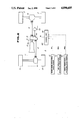
- FIG. 1 is a diagramatic view of a driving force distribution control device for a four wheel drive vehicle according to an embodiment of the present invention
- FIG. 2 is a schematic view of a driving force distribution control device for a four wheel drive vehicle according to another embodiment of the present invention
- FIG. 3 is a fragmentary sectional view of a transfer employed in the emboidment of FIG. 2;
- FIG. 4 is a block diagram of a control unit employed in the embodiment of FIG. 2;
- FIG. 5 is a graph depicting a relation between a clutch operating fluid pressure and a clutch engaging force
- FIG. 6 is a graph depicting a relation between a command current and a clutch operating fluid pressure
- FIG. 7 is a flow chart depicting a driving force distribution control routine of the control unit of FIG. 4;
- FIG. 8 is a flow chart depicting a control routine of the control unit of FIG. 4 during coasting (running at constant speed) and accelerated running;
- FIG. 9 is a flow chart depicting a control routine of the control unit of FIG. 4 during decelerated running
- FIG. 10 is a graph depicting a characteristic of gain for vehicle speed
- FIG. 11 is a graph depicting a characteristic of rotational speed differential between front and rear wheels for vehicle speed
- FIG. 12 is a flow chart of a control routine of the control unit of FIG. 4 during high speed running.
- FIG. 13 is a graph depicting a characteristic of clutch engaging force for vehicle speed.
- a driving force distribution control device for a four wheel drive vehicle is disposed in a drive train 4 for transmitting a driving force from an engine 5 to front and rear wheels 6 and 7.
- the control device consists of a clutch means 1 for distributing a driving force from the engine 5 to the front and rear wheels 6 and 7, a detecting means 2 for detecting a vehicle running condition and producing a signal representative thereof, and a clutch control means 3 responsive to the signal from the detecting means 2 for producing a control signal for controlling increase and decrease of a clutch engaging force.
- the detecting means 2 includes a front and rear wheel rotational speed differential detecting means 201 and a vehicle speed detecting means 202.
- the clutch means 3 includes a first computing means 301 for computing a clutch engaging force using a rotational speed differential between the front and rear wheels, a second computing 302 means for computing a clutch engaging force using only a vehicle speed, and a third computing means 303 for computing a target clutch engaging force from the sum of the computation results by the first and second computing means 301 and 302.
- the target clutch engaging force is computed by the third computing means 303 using the clutch engaging force which is computed by the first computing means 301 using the rotational speed differential between the front and rear wheels during low to middle speed coasting (running at constant speed), accelerated running and decelerated running.
- a good cornering or turning ability can be attained during coasting and accelerated running, and a good running stability can be attained during decelerated running.
- a target clutch engaging force is computed by the third computing means 303 from the sum of the clutch engaging force which is computed by the first computing means 301 using the rotational speed differential between the front and rear wheels and the clutch engaging force which is computed by the second computing means 302 using the vehicle speed.
- the clutch is brought into engagement prior to occurence of the rotational speed differential between the front and rear wheels, thus making it possible to attain a good running stability of the vehicle at the time of lane change or when subjected to a small disturbance. Further, during high speed cornering, weak understeer which effects a low vehicle head turning ability is attained by the clutch enagement controlled in accordance with the vehicle speed, thus making it possible for the driver to operate the steering wheel with ease even during high speed cornering.
- the driving force distribution device is generally indicated by the reference character "D" and installed on a four wheel drive vehicle having a transfer mechanism or transfer 10, engine 11, transmission 12, transfer input shaft 13 directly connected to the output shaft 12a of the transmission 12, rear wheel side drive shaft 14, multi-disc friction clutch 15, rear differential 16, a pair of left and right rear wheels 17 and 17, front differential 18, a pair of left and right front wheels 19 and 19, gear train 20 and front wheel side drive shaft 21.
- the multi-disc friction clutch 15 is disposed between the transfer input shaft 13 directly connected to the front wheel drive shaft 21 through the gear train 20 and the rear wheel side drive shaft 14 so that the troque transmitted to the front wheels 19 and 19 can be variably controlled by controlling a clutch operating fluid pressure.
- the transfer 10 includes a transfer case 22 within which the multi-disc friction clutch 15, gearing and shafting are disposed.
- the transfer clutch 15 includes a clutch drum 15a fixed to the transfer input shaft 13 and the rear wheel side drive shaft 14, friction plates 15b engaged with the clutch drum 15a so as to prevent relative rotation therebetween, a clutch hub 15c rotatably mounted on the transfer input shaft 13, friction discs 15d engaged with the clutch hub 15c so as to prevent relative rotation therebetween and alternated with the friction plates 15b, a clutch piston 15e provided at one side of the alternating friction plates and discs 15b and 15d, and a cylinder chamber 15f formed between the clutch piston 15e and the clutch drum 15a.
- the gear train 20 of the transfer 10 includes a first gear 20a provided to the clutch hub 15c of the transfer clutch 15, a second gear 20c provided to an intermediate shaft 20b, and a third gear 20d provided to the front drive shaft 21.
- first gear 20a provided to the clutch hub 15c of the transfer clutch 15
- second gear 20c provided to an intermediate shaft 20b
- third gear 20d provided to the front drive shaft 21.
- the transfer 10 further includes a dish plate 15g, a return spring 15h, a clutch operating fluid inlet port 24, a clutch operating fluid passage 25, a rear wheel side output shaft 26, a lubrication oil passage 27, a pinion for a speedometer 28, an oil seal 29, a bearing 30, a needle bearing 31, a thrust bearing 32 and a coupling flange 33 for connecting the output shaft 26 to the rear wheel side drive shaft 14.
- a fluid pressure controller 40 for supplying a clutch operating fluid pressure to the multi-disc friction clutch 15 for engagement thereof is, as shown in FIG. 4, provided with a rear wheel rotational speed sensor 41, left front wheel rotational speed sensor 42 and right front wheel rotational speed sensor 43.
- the controller 40 is further provided with a control unit 45 and a relief valve 46 of an electromagnetically proportional type, i.e., of the type of which degree of opening varies with variation of electromagnetic force.
- each sensors may, for example, be of the type as a rotational sensor consisting of a sensor rotor fixed to a shaft for measurement of rotational speed and a pickup for detecting an electromagnetic variation caused by variation in rotation of the sensor rotor.
- the sensors 41, 42 and 43 produce signals Nr, wf1 and wf2 representative of the rotational speeds of the respective vehicle wheels which are proportional to the rotational speeds of the shafts on which the sensors are respectively installed.
- the control unit 45 consists of a control circuit including a microcomputer installed on the vehicle body.
- the control circuit includes an input interface 451, RAM 452, ROM 453, CPU 454 and output interface 455.
- the left front wheel rotational speed Wfl, right front wheel rotational speed Wf2 and rear wheel rotational speed Nr detected by the respective sensors 41, 42 and 43 are read and stored.
- the vehicle speed Vf, front and rear wheel rotational speed differential ⁇ N and left and right front wheel rotation speed differential ⁇ n are calculated using the left front wheel rotational speed Wf1 and right front wheel rotational speed Wf2 read at the step "a" and using the tire radius r.
- the vehicle speed Vf is calculated using the smaller one of the left and right front wheel rotation speeds Wf1 and Wf2 and the tire radius r from the following formula.
- the vehicle speed Vf may be calculated using the average of the left and right front wheel rotational speeds Wf1 and Wf2 or may be obtained by direct measurement of an absolute vehicle speed.
- the front and rear wheel rotation speed differential ⁇ N is calculated using the rear wheel rotational speed Nr and the average of the front wheel rotational speeds Wf1 and Wf2 from the following formula.
- the front and rear wheel rotational speed differential ⁇ N may be obtained by direct measurement of the front and rear wheel rotational speed differential.
- the left and right front wheel rotational speed differential ⁇ n is calculated using the left front wheel rotational speed Wf1 and the right front wheel rotational speed Wf2 from the following formula.
- the left and right front wheel rotation speed differential ⁇ n is used for calculating the turning or cornering curve radius R and the lateral acceleration Yg.
- the cornering curve radius R may be
- the lateral acceleration Yg may be directly detected using a lateral acceleration sensor or the like.
- step "b” onward two control processings are performed in parallel, i.e., one control processing proceeds to the step “d” (control during coasting and accelerated running) or the step “e” (control during decelerated running) selectively based on the determination at the step “c" whilst the other control processing proceeds to the step “f" (control during high speed running).
- the lateral acceleration Yg is first calculated using the left and right front wheel rotational speed differential ⁇ n and the vehicle speed Vf, and then the clutch engaging force Tx is calculated using the lateral acceleration Yg and the front and rear wheel rotational speed differential ⁇ N.
- the details of the processing content ⁇ 1 are shown in FIG. 8 and will be described hereinafter with reference thereto.
- the clutch engaging force Tneg is calcuated using the vehicle speed Vf and the absolute value of the front and rear wheel rotational speed differential
- the details of the processing content ⁇ 2 at the step “d” are shown in FIGS. 9 to 11 and will be described hereinafter with reference thereto.
- the clutch engagement force Tv is calculated using only the vehicle speed Vf.
- the details of the processing content ⁇ 3 are shown in FIGS. 12 and 13 and will be described hereinafter with reference thereto.
- the target clutch engagement force T* is obtained from the sum of the clutch engagement forces Tx, Tneg and Tv from the following formula.
- a clutch operating fluid pressure control signal "i" capable of attaining the target clutch engagement force T* is produced by the relief valve 46.
- the cornering curve radius R is calculated using the various data obtained at the step "b" from the following formula. ##EQU1##
- a cornering curve radius variation ⁇ R to a unit time is calculated using the cornering curve radius R obtained at the step 100 and the cornering curve radius R o obtained at the previous control cycle.
- step 102 it is determined whether ⁇ R is positive or negative and thereby determining whether the cornering curve radius R is increasing or decreasing.
- ⁇ R is determined negative at the step 102, i.e., the cornering curve radius R is increasing
- the predetermined value A4 becomes the criteria of the low-pass filter when the cornering curve radius R is increasing.
- control processing proceeds to the step 105 to set the calculated cornering curve radius R as the cornering curve radius Rx without making any modification thereto.
- ⁇ R is determined negative at the step 102, i.e., the cornering curve radius R is decreasing
- the amount of variation is larger than a predetermined value A5.
- the predetermined value A5 becomes the criteria for the low-pass filter when the cornering curve raidius is decreasing.
- the set value A5 is larger than the set value A.
- control processing proceeds to the step 108 to set the calculated cornering curve radius R as the cornering curve radius Rx without making any modification thereto.
- the cornering curve radius Rx obtained at the latest control cycle is stored as R o for calculating ⁇ R.
- the lateral acceleration Yg is calculated using the cornering curve radius Rx processed by the low-pass filtering and the vehicle speed Vf from the following formula. ##EQU2##
- a proportional coefficient (gain) k is calculated using the above lateral acceleration Yg from the following formula. ##EQU3##
- a correction value ⁇ Nx is obtained for correction of the front and rear wheel rotational speed differential ⁇ N obtained at the step "b".
- the clutch engaging force Tx becomes generally equal to the clutch engaging force Th that is obtained by processing the proportional coefficient K by filtering.
- the proportional coefficient K is indirectly determined from the lateral acceleration Yg by processing the turning radius R by filtrin.
- the clutch engaging force Tx is at least larger than a predetermined clutch enaging force Tl which is determined by experiments so as not to become an extremely small value.
- the gain Kneg is obtained from the function of the vehicle speed Vf.
- the clutch engaging force Tneg is calculated using the gain Kneg obtained at the step 200 and the absolute value of the front and rear wheel rotational speed differential
- the clutch engaging force Tv is calculated using the function of only the vehicle speed vf from the following formula.
- the function of the vehicle speed f(Vf) is such one as shwon in FIG. 13. Since a main object of increasing the clutch engaging force in response to vehicle speed resides in attaining the running stability at high speed, the vehicle speed V2 which is a minimum vehicle speed for allowing the clutch engaging force Tv to become equal to or larger than zero is about 80 Km/h whilst the vehicle speed V3 at which the clutch engaging force Tv reaches the maximum clutch engaging force Tvmax is about 120 km/h such that the function of the vehicle speed does not affect the vehicle cornering ability at low to middle speed.
- the maximum clutch engaging force Tvmax is of such a value that is capable of ataining the high speed running stability and that is sufficient for making the steering characteristic during accelerated cornering to become weak understeer.
- the target clutch engaging force T* is determined mainly based on the clutch engaging force Tx. Accordingly, an excellent cornering ability is attained.
- the target clutch engaging force T* is determined mainly based on the clutch engaging force Tneg unless at high speed.
- the target clutch engaging force T* is calculated mainly from the sum of the clutch engaging force Tx and the clutch engaging force Tv.
- a driving force distribution device "D" for a four wheel drive vehicle is adapted to obtain a target clutch engaging force T* from the sum of a clutch enagaging force Tx or Tneg obtained based on only a front and rear wheel rotational speed differential ⁇ N and a clutch engaging force Tv obtained based on only a vehicle speed Vf, thus making it possible to attain all of an accelerated and decelerated running stability at low to middle speed and an optimal steering characteristic during high speed straightahead running.
- multi-disc friction clutch has been employed as the clutch means, it may be an electromagnetic clutch, viscous clutch or the like.
Landscapes
- Engineering & Computer Science (AREA)
- Chemical & Material Sciences (AREA)
- Combustion & Propulsion (AREA)
- Transportation (AREA)
- Mechanical Engineering (AREA)
- Arrangement And Driving Of Transmission Devices (AREA)
Applications Claiming Priority (2)
| Application Number | Priority Date | Filing Date | Title |
|---|---|---|---|
| JP62-302472 | 1987-11-30 | ||
| JP62302472A JP2528484B2 (ja) | 1987-11-30 | 1987-11-30 | 四輪駆動車の駆動力配分制御装置 |
Publications (1)
| Publication Number | Publication Date |
|---|---|
| US4890685A true US4890685A (en) | 1990-01-02 |
Family
ID=17909360
Family Applications (1)
| Application Number | Title | Priority Date | Filing Date |
|---|---|---|---|
| US07/277,377 Expired - Lifetime US4890685A (en) | 1987-11-30 | 1988-11-29 | Device for controlling driving force distribution in four-wheel drive vehicle |
Country Status (4)
| Country | Link |
|---|---|
| US (1) | US4890685A (ja) |
| EP (1) | EP0319830B1 (ja) |
| JP (1) | JP2528484B2 (ja) |
| DE (1) | DE3863765D1 (ja) |
Cited By (15)
| Publication number | Priority date | Publication date | Assignee | Title |
|---|---|---|---|---|
| US5010974A (en) * | 1989-04-10 | 1991-04-30 | Nissan Motor Co., Ltd. | 4WD vehicle with driving force distribution control |
| US5132908A (en) * | 1989-04-28 | 1992-07-21 | Nissan Motor Co., Ltd. | Driving force distribution control system for a fourwheel drive vehicle |
| US5168955A (en) * | 1989-10-09 | 1992-12-08 | Nissan Motor Company, Limited | Traction control system for four-wheel drive vehicle |
| US5197566A (en) * | 1990-01-19 | 1993-03-30 | Mazda Motor Corporation | Differential control system for four-wheel drive vehicle |
| US5346032A (en) * | 1992-06-08 | 1994-09-13 | Nissan Motor Co., Ltd. | Torque distribution control system for four wheel drive vehicle |
| US5839084A (en) * | 1994-09-21 | 1998-11-17 | Nissan Motor Co., Ltd. | Driving-torque control system for four-wheel-drive vehicle |
| US6029511A (en) * | 1996-09-04 | 2000-02-29 | Bayerische Motoren Werke Aktiengesellschaft | Method and apparatus for improving vehicle driving stability during deceleration |
| US6038506A (en) * | 1996-07-01 | 2000-03-14 | Claas Kgaa | Arrangement for and method of automatically controlling a differential lock in drive axles of a motor vehicle |
| US6553303B2 (en) * | 2000-06-29 | 2003-04-22 | Fuji Jukogyo Kabushiki Kaisha | Driving force distribution control system and vehicle having the driving force distribution control system |
| US6663536B1 (en) * | 1999-10-19 | 2003-12-16 | Bayerische Motoren Werke Aktiengesellschaft | Control system for variable torque distribution for a four-wheel-drive vehicle |
| US20040054459A1 (en) * | 2002-09-13 | 2004-03-18 | Brooks Cary Walter | Drive torque transfer scheme |
| US20040059493A1 (en) * | 2002-09-24 | 2004-03-25 | Fuji Jukogyo Kabushiki Kaisha | Slip control device of four-wheel-drive vehicle |
| US20050209763A1 (en) * | 2004-03-18 | 2005-09-22 | Ford Global Technologies, Llc | Method and apparatus for controlling brake-steer in an automotive vehicle in reverse |
| US20050206231A1 (en) * | 2004-03-18 | 2005-09-22 | Ford Global Technologies, Llc | Method and apparatus for controlling an automotive vehicle using brake-steer and normal load adjustment |
| US20050236896A1 (en) * | 2004-03-18 | 2005-10-27 | Ford Global Technologies, Llc | Method and apparatus of controlling an automotive vehicle using brake-steer as a function of steering wheel torque |
Families Citing this family (7)
| Publication number | Priority date | Publication date | Assignee | Title |
|---|---|---|---|---|
| JPH0829670B2 (ja) * | 1988-02-18 | 1996-03-27 | 日産自動車株式会社 | 前後輪駆動力配分制御車両の補助操舵方法 |
| JPH0794207B2 (ja) * | 1989-04-19 | 1995-10-11 | 日産自動車株式会社 | 四輪駆動車の駆動力配分制御装置 |
| JP2934457B2 (ja) * | 1989-08-28 | 1999-08-16 | 富士重工業株式会社 | 4輪駆動車の不等トルク配分制御装置 |
| FR2787070B1 (fr) * | 1998-12-10 | 2001-01-26 | Jean Claude Favarel | Transmission pour vehicule comportant au moins deux essieux moteur |
| AU2000226779A1 (en) * | 2000-02-15 | 2001-08-27 | Jean-Claude Favarel | Motor vehicle transmission |
| DE10346671A1 (de) * | 2003-10-08 | 2005-05-12 | Bayerische Motoren Werke Ag | Steuersystem für ein zumindest zeitweise vierradgetriebenes Kraftfahrzeug |
| DE10346673A1 (de) | 2003-10-08 | 2005-05-12 | Bayerische Motoren Werke Ag | Steuersystem für ein zumindest zeitweise vierradgetriebenes Kraftfahrzeug |
Citations (4)
| Publication number | Priority date | Publication date | Assignee | Title |
|---|---|---|---|---|
| JPS61157437A (ja) * | 1984-12-28 | 1986-07-17 | Nissan Motor Co Ltd | 4輪駆動車の駆動力配分制御装置 |
| US4754834A (en) * | 1985-01-21 | 1988-07-05 | Nissan Motor Co., Ltd. | Four wheel drive system having driving force distribution control responsive to vehicle lateral acceleration |
| US4773500A (en) * | 1985-09-13 | 1988-09-27 | Nissan Motor Co., Ltd. | Driving torque distribution control system for 4WD vehicle |
| US4776424A (en) * | 1985-08-05 | 1988-10-11 | Nissan Motor Co., Ltd. | Driving force distribution control system for 4WD vehicle |
Family Cites Families (2)
| Publication number | Priority date | Publication date | Assignee | Title |
|---|---|---|---|---|
| DE3427725A1 (de) * | 1984-02-14 | 1985-08-22 | Volkswagenwerk Ag, 3180 Wolfsburg | Anordnung zum regeln der kraftuebertragung eines vierradgetriebenen kraftfahrzeuges mit verteilergetriebe |
| JPS61193931A (ja) * | 1985-02-25 | 1986-08-28 | Nissan Motor Co Ltd | 4輪駆動車の駆動力配分制御装置 |
-
1987
- 1987-11-30 JP JP62302472A patent/JP2528484B2/ja not_active Expired - Fee Related
-
1988
- 1988-11-29 US US07/277,377 patent/US4890685A/en not_active Expired - Lifetime
- 1988-11-29 DE DE8888119907T patent/DE3863765D1/de not_active Expired - Lifetime
- 1988-11-29 EP EP88119907A patent/EP0319830B1/en not_active Expired
Patent Citations (4)
| Publication number | Priority date | Publication date | Assignee | Title |
|---|---|---|---|---|
| JPS61157437A (ja) * | 1984-12-28 | 1986-07-17 | Nissan Motor Co Ltd | 4輪駆動車の駆動力配分制御装置 |
| US4754834A (en) * | 1985-01-21 | 1988-07-05 | Nissan Motor Co., Ltd. | Four wheel drive system having driving force distribution control responsive to vehicle lateral acceleration |
| US4776424A (en) * | 1985-08-05 | 1988-10-11 | Nissan Motor Co., Ltd. | Driving force distribution control system for 4WD vehicle |
| US4773500A (en) * | 1985-09-13 | 1988-09-27 | Nissan Motor Co., Ltd. | Driving torque distribution control system for 4WD vehicle |
Cited By (19)
| Publication number | Priority date | Publication date | Assignee | Title |
|---|---|---|---|---|
| US5010974A (en) * | 1989-04-10 | 1991-04-30 | Nissan Motor Co., Ltd. | 4WD vehicle with driving force distribution control |
| US5132908A (en) * | 1989-04-28 | 1992-07-21 | Nissan Motor Co., Ltd. | Driving force distribution control system for a fourwheel drive vehicle |
| US5168955A (en) * | 1989-10-09 | 1992-12-08 | Nissan Motor Company, Limited | Traction control system for four-wheel drive vehicle |
| US5197566A (en) * | 1990-01-19 | 1993-03-30 | Mazda Motor Corporation | Differential control system for four-wheel drive vehicle |
| US5346032A (en) * | 1992-06-08 | 1994-09-13 | Nissan Motor Co., Ltd. | Torque distribution control system for four wheel drive vehicle |
| US5839084A (en) * | 1994-09-21 | 1998-11-17 | Nissan Motor Co., Ltd. | Driving-torque control system for four-wheel-drive vehicle |
| US6038506A (en) * | 1996-07-01 | 2000-03-14 | Claas Kgaa | Arrangement for and method of automatically controlling a differential lock in drive axles of a motor vehicle |
| US6029511A (en) * | 1996-09-04 | 2000-02-29 | Bayerische Motoren Werke Aktiengesellschaft | Method and apparatus for improving vehicle driving stability during deceleration |
| US6663536B1 (en) * | 1999-10-19 | 2003-12-16 | Bayerische Motoren Werke Aktiengesellschaft | Control system for variable torque distribution for a four-wheel-drive vehicle |
| US6553303B2 (en) * | 2000-06-29 | 2003-04-22 | Fuji Jukogyo Kabushiki Kaisha | Driving force distribution control system and vehicle having the driving force distribution control system |
| US20040054459A1 (en) * | 2002-09-13 | 2004-03-18 | Brooks Cary Walter | Drive torque transfer scheme |
| US6810318B2 (en) | 2002-09-13 | 2004-10-26 | General Motors Corporation | Drive torque transfer scheme |
| US20040059493A1 (en) * | 2002-09-24 | 2004-03-25 | Fuji Jukogyo Kabushiki Kaisha | Slip control device of four-wheel-drive vehicle |
| US7127343B2 (en) * | 2002-09-24 | 2006-10-24 | Fuji Jukogyo Kabushiki Kaisha | Slip control device of four-wheel-drive vehicle |
| US20050209763A1 (en) * | 2004-03-18 | 2005-09-22 | Ford Global Technologies, Llc | Method and apparatus for controlling brake-steer in an automotive vehicle in reverse |
| US20050206231A1 (en) * | 2004-03-18 | 2005-09-22 | Ford Global Technologies, Llc | Method and apparatus for controlling an automotive vehicle using brake-steer and normal load adjustment |
| US20050236896A1 (en) * | 2004-03-18 | 2005-10-27 | Ford Global Technologies, Llc | Method and apparatus of controlling an automotive vehicle using brake-steer as a function of steering wheel torque |
| US7165644B2 (en) | 2004-03-18 | 2007-01-23 | Ford Global Technologies, Llc | Method and apparatus of controlling an automotive vehicle using brake-steer as a function of steering wheel torque |
| US8380416B2 (en) * | 2004-03-18 | 2013-02-19 | Ford Global Technologies | Method and apparatus for controlling brake-steer in an automotive vehicle in reverse |
Also Published As
| Publication number | Publication date |
|---|---|
| JPH01145228A (ja) | 1989-06-07 |
| EP0319830A1 (en) | 1989-06-14 |
| JP2528484B2 (ja) | 1996-08-28 |
| DE3863765D1 (de) | 1991-08-22 |
| EP0319830B1 (en) | 1991-07-17 |
Similar Documents
| Publication | Publication Date | Title |
|---|---|---|
| US4890685A (en) | Device for controlling driving force distribution in four-wheel drive vehicle | |
| US4887689A (en) | Driving force distribution control system for 4WD vehicle | |
| US4846298A (en) | Driving force distribution control system for 4WD vehicle | |
| US5168953A (en) | Differential limiting force control system and method for vehicle | |
| US4936406A (en) | Power transmitting system for a four-wheel drive vehicle | |
| US5184298A (en) | Rear wheel steering system for vehicle | |
| US5033329A (en) | System for controlling distribution of torque to left and right wheels of a motor vehicle | |
| JPH0424253B2 (ja) | ||
| JPS63176728A (ja) | トルク配分制御装置付4輪駆動車 | |
| JPS63203421A (ja) | 四輪駆動車の駆動力配分制御装置 | |
| EP0262908B1 (en) | System for controlling a transfer clutch of a fourwheel drive vehicle | |
| JPS62143720A (ja) | 四輪駆動車の駆動力配分制御装置 | |
| JP2552321B2 (ja) | 四輪駆動車の駆動力配分比検出装置 | |
| JP2534723B2 (ja) | 四輪駆動車の駆動力配分制御装置 | |
| JPH0425899B2 (ja) | ||
| JPH04154437A (ja) | 四輪駆動車の駆動力制御装置 | |
| JP2502735B2 (ja) | 四輪駆動車の駆動力配分制御装置 | |
| JP2641498B2 (ja) | 差動制限トルク制御装置 | |
| JPH0825399B2 (ja) | 車両用駆動系クラツチ制御装置 | |
| JP2600716B2 (ja) | 車両用駆動力配分制御装置 | |
| JPH078614B2 (ja) | 車両の後輪駆動装置 | |
| JPH01182129A (ja) | 4輪駆動,4輪操舵自動車の駆動力配分及び後輪操舵角の制御方法 | |
| JPH07108619B2 (ja) | 四輪駆動車の駆動力配分制御装置 | |
| JP2631850B2 (ja) | 4輪操舵4輪駆動車 | |
| JPH02106439A (ja) | 前後輪駆動車両用差動制御クラッチの制御方法 |
Legal Events
| Date | Code | Title | Description |
|---|---|---|---|
| AS | Assignment |
Owner name: NISSAN MOTOR CO., LTD., NO., JAPAN Free format text: ASSIGNMENT OF ASSIGNORS INTEREST.;ASSIGNOR:NAITO, GENPEI;REEL/FRAME:005023/0750 Effective date: 19881221 |
|
| STCF | Information on status: patent grant |
Free format text: PATENTED CASE |
|
| FEPP | Fee payment procedure |
Free format text: PAYOR NUMBER ASSIGNED (ORIGINAL EVENT CODE: ASPN); ENTITY STATUS OF PATENT OWNER: LARGE ENTITY |
|
| FPAY | Fee payment |
Year of fee payment: 4 |
|
| FPAY | Fee payment |
Year of fee payment: 8 |
|
| FPAY | Fee payment |
Year of fee payment: 12 |