US4783159A - Operation microscope - Google Patents
Operation microscope Download PDFInfo
- Publication number
- US4783159A US4783159A US07/031,523 US3152387A US4783159A US 4783159 A US4783159 A US 4783159A US 3152387 A US3152387 A US 3152387A US 4783159 A US4783159 A US 4783159A
- Authority
- US
- United States
- Prior art keywords
- objective lens
- optical axis
- single objective
- illumination
- optical
- Prior art date
- Legal status (The legal status is an assumption and is not a legal conclusion. Google has not performed a legal analysis and makes no representation as to the accuracy of the status listed.)
- Expired - Lifetime
Links
- 230000003287 optical effect Effects 0.000 claims abstract description 77
- 238000005286 illumination Methods 0.000 claims abstract description 36
- 239000013307 optical fiber Substances 0.000 claims description 5
- 230000005540 biological transmission Effects 0.000 claims 7
- 230000004907 flux Effects 0.000 claims 2
- 230000002093 peripheral effect Effects 0.000 claims 1
- 241000459479 Capsula Species 0.000 abstract description 7
- 208000002177 Cataract Diseases 0.000 abstract description 2
- 238000010276 construction Methods 0.000 abstract 1
- 230000013011 mating Effects 0.000 description 1
- 230000004048 modification Effects 0.000 description 1
- 238000012986 modification Methods 0.000 description 1
- 210000001747 pupil Anatomy 0.000 description 1
Images


Classifications
-
- G—PHYSICS
- G02—OPTICS
- G02B—OPTICAL ELEMENTS, SYSTEMS OR APPARATUS
- G02B21/00—Microscopes
- G02B21/18—Arrangements with more than one light path, e.g. for comparing two specimens
- G02B21/20—Binocular arrangements
- G02B21/22—Stereoscopic arrangements
-
- A—HUMAN NECESSITIES
- A61—MEDICAL OR VETERINARY SCIENCE; HYGIENE
- A61B—DIAGNOSIS; SURGERY; IDENTIFICATION
- A61B3/00—Apparatus for testing the eyes; Instruments for examining the eyes
- A61B3/10—Objective types, i.e. instruments for examining the eyes independent of the patients' perceptions or reactions
- A61B3/13—Ophthalmic microscopes
- A61B3/132—Ophthalmic microscopes in binocular arrangement
-
- A—HUMAN NECESSITIES
- A61—MEDICAL OR VETERINARY SCIENCE; HYGIENE
- A61B—DIAGNOSIS; SURGERY; IDENTIFICATION
- A61B90/00—Instruments, implements or accessories specially adapted for surgery or diagnosis and not covered by any of the groups A61B1/00 - A61B50/00, e.g. for luxation treatment or for protecting wound edges
- A61B90/36—Image-producing devices or illumination devices not otherwise provided for
-
- G—PHYSICS
- G02—OPTICS
- G02B—OPTICAL ELEMENTS, SYSTEMS OR APPARATUS
- G02B21/00—Microscopes
- G02B21/06—Means for illuminating specimens
- G02B21/08—Condensers
- G02B21/082—Condensers for incident illumination only
-
- G—PHYSICS
- G02—OPTICS
- G02B—OPTICAL ELEMENTS, SYSTEMS OR APPARATUS
- G02B21/00—Microscopes
- G02B21/06—Means for illuminating specimens
- G02B21/08—Condensers
- G02B21/12—Condensers affording bright-field illumination
Definitions
- This invention relates to an operation microscope for use in ophthalmic and surgical operations and more particularly to a microscope for use in surgical operations in which two observation rays entering respectively to the left and right eyes of an operator and illumination rays pass through a single objective lens.
- the microscope for use in surgical operations in ophthalmology and otorhinology it is preferable to so construct the microscope that the illumination rays and the observation rays cross each other at the smallest possible angle in order to illuminate deep parts of the diseased tissue.
- a microscope to confirm whether or not a part of the lens of an eye remains in the capsula lentis after the removal of the lens in a cataract operation, it is impossible to reliably confirm the presence or absence of any remaining part of the lens by illuminating the lens and the capsula lentis from the front side thereof, since both the lens and the capsula lentis are transparent. Accordingly, it has been the usual practice to confirming whether any part of the lens remains by illuminating the fundus through the capsula lentis so that rays reflected by the fundus pass through the capsula lentis from the back side thereof.
- this prior art microscope in which the illumination rays enter the single objective lens at the periphery thereof, has a problem in that it is impossible to sufficiently illuminate deep parts of the diseased tissue because of misalignment of the optical axes of the observation rays and the illumination rays.
- an operation microscope having a pair of observation optical systems behind a single objective lens characterized in that the microscope is provided with an illumination apparatus behind said single objective lens, said illumination apparatus having an exit optical axis in alignment with an optical axis of said single objective lens and a reflecting member for reflecting illumination rays.
- said reflecting member is disposed in a space between said single objective lens and said observation optical systems.
- said refecting member is so mounted that it can be selectively moved in and out of the optical axis of the objective lens.
- said illumination apparatus comprises illumination means for generating illumination rays at a position outside said optical axis of the single objective lens, and optical transmitting means for directing one part of the illumination rays to said reflecting member.
- said optical transmitting means is a reflecting member for reflecting the illumination rays toward said reflecting member.
- FIG. 1 is a perspective view showing the structural arrangement of the main optical parts of the operation microscope of the present invention
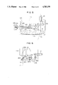
- FIG. 2 is a longitudinal cross-sectional view of the microscope of the present invention
- FIG. 3 is a cross-sectional view taken along lines III--III of FIG. 2,
- FIG. 4 is a cross-sectional view taken along lines IV--IV of FIG. 2,
- FIG. 5 is a longitudinal cross-sectional view showing a second embodiment of the present invention.
- FIG. 6 is a longitudinal cross-sectional view showing a third embodiment of the present invention.
- FIG. 1 is a perspective view of the optical arrangement of the microscope for surgical operation of the present invention.
- a first observation optical system 11 to be used by the operator is positioned above a single objective lens 10 used by both the left and right eyes of the operator.
- the first observation optical system 11 comprises a variable power zoom optical system 11a for the left eye, a variable power zoom optical system 11b for the right eye, erecting optical systems respectively for the left and right eyes, and eyepieces (not shown).
- Reflecting prisms 13a and 13b are disposed between the objective lens 10 and the first observation optical system 11 for the operator.
- a plane including incident optical axes O 3a and O 3b entering the reflecting prisms 13a and 13b and a plane including optical axes O 2a and O 2b of the first observation optical system 11 cross each other at a position through which an optical axis O 1 of the objective lens 10 passes.
- the incident optical axes O 3a O 3b entering the reflecting prisms 13a and 13b are refracted respectively by reflecting surfaces 130a and 130b of the reflecting prisms and exit optical axes O' 3a and O' 3b exiting from the reflecting prisms 13a and 13b are included in a plane perpendicular to the optical axis O 1 of the objective lens 10.
- These exit optical axes O' 3a and O' 3b are reflected by a reflecting mirror 20 and emitted as incident optical axes to a known assistant microscope which use a common objective lens with the objective lens of the operation microscope.
- An illumination optical system 15 is disposal at one side of the first observation optical system 11.
- the illumination optical system 15 comprises an optical fiber 19 for guiding rays from a light source (not shown), a variable power zoom optical system 16 for varying the illumination field, and a projection lens 17.
- the illumination rays passing through the projecting lens 17 pass through the objective lens 10 and illuminate a diseased tissue such as an eye E to be operated on.
- One part of the illumination rays from the projecting lens 17 enter a reflecting prism 18 and illuminate the eye E to be operated on through the objective lens 10 after having been reflected by two reflecting surfaces 18a and 18b of the prism 18.
- an exit optical axis O 4 from the reflecting prism 18 is in alignment with the optical axis O 1 of the objective lens 10 and passes through the optical axis O 1 . Accordingly, the illumination rays from the reflecting prism 18 pass along the optical axis O 1 of the objective lens 10 and make it possible to illuminate deep parts of the eye E to be operated on.
- FIGS. 2 through 4 shows the mechanical structure of the microscope embodying the above mentioned optical system of the present invention.
- the first observation optical system 11 and the illumination optical system 15 are disposed within a housing i.e. a barrel 30.
- the variable power zoom optical systems 11a and 11b (11b is not shown) of the first observation optical system and the variable power zoom optical system 16 of the illumination optical system 15 are driven by a cam cylinder 31.
- the upper inside surface of the cam cylinder 31 is provided with gear teeth 35 mating with a driving gear 34 which is driven by an electric motor 32 through a reduction means 33.
- a bottom plate 36 of the barrel 30 Formed on a bottom plate 36 of the barrel 30 are two left and right openings 37a and 37b (37b is not shown) for the first observation optical system 11.
- the projecting lens 17 of the illumination optical system 15 is fitted within an opening 38 formed on the bottom plate 36.
- the reflecting prism 18 is mounted on a seat base 41 formed on one end of a swing arm 40.
- the swing arm 40 is swingably mounted on a stepped pin 43 fixed on the bottom plate 36 of the barrel 30.
- a pin 44 is fixed on the other end of the swing arm 40, as shown in FIG. 3.
- the pin 44 engages with a fork shaped piece 51 inserted into a ring 50 which is mounted on the barrel 30 rotatably around the optical axis O 1 of the objective lens 10.
- Formed on the external end of the fork shaped piece 51 is a thread 52 on which a sterilizeable knob 53 is detachably mounted. Only to this structure, it is possible to put the reflecting prism 18 within the illumination ray path and retract the prism 18 therefrom by rotating the knob 53 in the direction of an arrow 54 and therefore rotating the swing arm 40 around the pin 43.
- Another ring 60 is further mounted on the barrel 30 at the lower end thereof rotatably around the optical axis O 1 of the objective ens 10 as shown in FIG. 2.
- mounted on the ring 60 are two diametrically opposed supporting arms 62a and 62b respectively having seat bases 64a and 64b on which openings 63a and 63b are respectively formed.
- the seat bases 64a and 64b respectively support the reflecting prisms 13a and 13b thereon.
- An opening 66 is formed on the side wall of the ring 60 and forms a passage for the exit optical axes O' 3a and O' 3b from the reflecting prisms 13a and 13b.
- a mount 67 having a dovetail flange 65 projects from the opening 66 and supports the microscope for assistance, which has a dovetail flange 90, through dovetail connection.
- the objective lens 10 is threadably mounted on the lower end of the ring 60 through a screw mount 61.
- the microscope for assistant By rotating the ring 60 by a small angle in the direction of the arrow 70, the microscope for assistant can be rotated around the optical axis O 1 within a range in which the reflecting prisms 13a and 13b on the seat bases 64a and 64b do not block off the optical axes of the first observation system 11.
- the exit optical axes O' 3a and O' 3b of the reflecting prisms 13a and 13b can be turned to the position shown by dotted lines in FIG. 4 by rotating the ring 60 by 180°. Accordingly, it is possible to selectively position the microscope for assistant either at the lefthand side or at the righthand side of the operator.
- FIG. 5 shows a second embodiment of the present invention wherein the reflecting prism 18 is mounted on a seat base 101 of a slider 100.
- the slider 100 has a shank 102 which is slidably inserted into a bearing 103 of the barrel 30 in a direction perpendicular to the optical axis O 1 of the objective lens 10.
- the shank 102 is provided with a thread 104 on the external end thereof on which a sterilizeable knob 105 is threadably mounted.
- the knob 105 By pushing the knob 105 in the direction of the arrow 106, the reflecting prism 18 is horizontally moved and the reflecting surface 18a thereof is shifted to a position beneath the projecting lens 17 as shown by a phantom line. In this condition, one part of the illumination rays are projected through the optical axis O 1 of the objective lens 10.
- FIG. 6 shows a third embodiment of the present invention wherein a swing arm 200 is mounted on a pin 201 fixed on the barrel 30 swingably around the pin 201 along an arrow 202.
- a reflecting mirror 204 is mounted on a flange 203 formed on one end of the swing arm 200.
- Formed on the other end of the swing arm 200 is a flange 207 having an opening 207a through which one end of an optical fiber having rounded ends is passed.
- the other end of the optical fiber 205 is supported by a bracket 206 beneath the projecting lens 17.
Landscapes
- Physics & Mathematics (AREA)
- Health & Medical Sciences (AREA)
- Life Sciences & Earth Sciences (AREA)
- Chemical & Material Sciences (AREA)
- Analytical Chemistry (AREA)
- General Physics & Mathematics (AREA)
- Optics & Photonics (AREA)
- Surgery (AREA)
- Biomedical Technology (AREA)
- Animal Behavior & Ethology (AREA)
- Veterinary Medicine (AREA)
- Heart & Thoracic Surgery (AREA)
- Medical Informatics (AREA)
- Molecular Biology (AREA)
- Public Health (AREA)
- Engineering & Computer Science (AREA)
- General Health & Medical Sciences (AREA)
- Biophysics (AREA)
- Ophthalmology & Optometry (AREA)
- Nuclear Medicine, Radiotherapy & Molecular Imaging (AREA)
- Oral & Maxillofacial Surgery (AREA)
- Pathology (AREA)
- Microscoopes, Condenser (AREA)
Applications Claiming Priority (2)
| Application Number | Priority Date | Filing Date | Title |
|---|---|---|---|
| JP1986047963U JPH0720652Y2 (ja) | 1986-03-31 | 1986-03-31 | 手術用顕微鏡 |
| JP61-47963[U] | 1986-03-31 |
Publications (1)
| Publication Number | Publication Date |
|---|---|
| US4783159A true US4783159A (en) | 1988-11-08 |
Family
ID=12789994
Family Applications (1)
| Application Number | Title | Priority Date | Filing Date |
|---|---|---|---|
| US07/031,523 Expired - Lifetime US4783159A (en) | 1986-03-31 | 1987-03-26 | Operation microscope |
Country Status (2)
| Country | Link |
|---|---|
| US (1) | US4783159A (enExample) |
| JP (1) | JPH0720652Y2 (enExample) |
Cited By (27)
| Publication number | Priority date | Publication date | Assignee | Title |
|---|---|---|---|---|
| US5007723A (en) * | 1987-05-15 | 1991-04-16 | Storz Instrument Company | Documentation illumination module for a microscope system |
| FR2664066A1 (fr) * | 1988-09-30 | 1992-01-03 | Storz Instr Co | Microscope pour utilisateurs multiples avec dispositif d'eclairage. |
| FR2664392A1 (fr) * | 1990-07-03 | 1992-01-10 | Storz Instr Co | Microscope pour utilisateurs multiples avec dispositif de reglage de l'orientation, et son procede de reglage. |
| DE4028605A1 (de) * | 1990-09-08 | 1992-03-12 | Zeiss Carl Fa | Beleuchtungseinrichtung fuer ein operationsmikroskop |
| DE9306412U1 (de) * | 1993-04-28 | 1993-06-24 | J.D. Möller Optische Werke GmbH, 2000 Wedel | Operationsmikroskop mit einer Beleuchtungseinrichtung |
| US5227914A (en) * | 1990-07-18 | 1993-07-13 | Olympus Optical Co., Ltd. | Stereomicroscope including a single variable magnification optical system |
| DE4331635A1 (de) * | 1992-12-22 | 1994-06-23 | Zeiss Carl Fa | Beleuchtungseinrichtung für ein Operationsmikroskop mit optisch-mechanisch gekoppelten Beobachtertuben |
| EP0793128A1 (en) * | 1996-03-01 | 1997-09-03 | Mitaka Kohki Co., Limited | Illumination structure in microscope |
| EP1019705A4 (en) * | 1996-08-16 | 2001-02-28 | Imaging Res Inc | DIGITAL IMAGING SYSTEM FOR WELL PLATES, GELS AND STAINS |
| EP1109046A1 (de) * | 1999-12-15 | 2001-06-20 | Möller-Wedel GmbH | Beleuchtungseinrichtung für ein Operationsmikroskop |
| DE19822255C2 (de) * | 1998-05-18 | 2001-07-05 | Zeiss Carl Jena Gmbh | Auflicht-Beleuchtungsanordnung für ein Stereomikroskop |
| DE4214445C2 (de) * | 1992-05-06 | 2003-03-27 | Zeiss Carl | Beleuchtungseinrichtung für ein Operationsmikroskop |
| US6563113B1 (en) * | 1997-09-05 | 2003-05-13 | Leica Microsystems (Schweiz) Ag | Microscope, especially a fluorescence microscope, particularly a stereo fluorescence microscope |
| WO2003023483A3 (de) * | 2001-09-05 | 2003-10-16 | Europ Lab Molekularbiolog | Mikroskop |
| US20040085627A1 (en) * | 2002-08-22 | 2004-05-06 | Kabushiki Kaisha Topcon | Operation microscope |
| US20080239473A1 (en) * | 2007-03-30 | 2008-10-02 | Kazutoshi Takagi | Operation microscope |
| DE202007012470U1 (de) | 2007-09-06 | 2009-01-08 | Möller-Wedel GmbH | Operationsmikroskop mit Beleuchtung |
| DE202007012472U1 (de) | 2007-09-06 | 2009-01-08 | Möller-Wedel GmbH | Operationsmikroskop mit Beleuchtungseinrichtung |
| DE202007012431U1 (de) | 2007-09-05 | 2009-01-08 | Möller-Wedel GmbH | Operationsmikroskop mit einer Beleuchtungseinrichtung |
| DE202007012432U1 (de) | 2007-09-05 | 2009-01-08 | Möller-Wedel GmbH | Beleuchtungsvorrichtung für ein Operationsmikroskop |
| DE202007012471U1 (de) | 2007-09-06 | 2009-01-08 | Möller-Wedel GmbH | Operationsmikroskop mit Beleuchtungseinrichtung |
| US20090116102A1 (en) * | 2007-11-07 | 2009-05-07 | Kabushiki Kaisha Topcon | Stereomicroscope |
| DE102008008875A1 (de) | 2008-02-12 | 2009-08-13 | Hartmut Feuerbacher | LED Auflichteinrichtung für Stereomikroskope |
| DE102013206839A1 (de) * | 2013-04-16 | 2014-10-16 | Möller-Wedel GmbH & Co. KG | Operationsmikroskop mit Rotreflex-Beleuchtung |
| DE102015103426A1 (de) | 2015-03-09 | 2016-09-15 | Carl Zeiss Meditec Ag | Mikroskopsystem und Verfahren zum automatisierten Ausrichten eines Mikroskops |
| US20170146780A1 (en) * | 2015-11-24 | 2017-05-25 | Mitaka Kohki Co., Ltd. | Surgical stereoscopic observation apparatus |
| CN110998407A (zh) * | 2017-07-31 | 2020-04-10 | 株式会社高永科技 | 立体显微镜、光学装置及利用其的光路形成方法 |
Citations (7)
| Publication number | Priority date | Publication date | Assignee | Title |
|---|---|---|---|---|
| US4232933A (en) * | 1978-02-17 | 1980-11-11 | Olympus Optical Co., Ltd. | Optical system of colposcope |
| US4329015A (en) * | 1978-09-25 | 1982-05-11 | Designs For Vision, Inc. | Apparatus for increasing the input light intensity to a microscope |
| US4361379A (en) * | 1979-08-10 | 1982-11-30 | Firma J. D. Moller Optische Werke GmbH | Surgery microscope with cut-through form lens with a light barrier |
| US4428035A (en) * | 1981-12-05 | 1984-01-24 | Carl-Zeiss-Stiftung | Electronic flashlight for ophthalmological examination instruments |
| US4479700A (en) * | 1981-06-22 | 1984-10-30 | Kuniomi Abe | Microscope |
| US4614411A (en) * | 1985-05-16 | 1986-09-30 | Carl-Zeiss-Stiftung, Heidenheim/Brenz | Microscope with correlatable fixation target |
| US4657357A (en) * | 1984-10-23 | 1987-04-14 | Tokyo Kogaku Kikai Kabushiki Kaisha | Illumination system for single objective lens binocular microscope |
Family Cites Families (2)
| Publication number | Priority date | Publication date | Assignee | Title |
|---|---|---|---|---|
| JPS5317353A (en) * | 1976-07-30 | 1978-02-17 | Tokyo Optical | Binocular solid microscope for multiple observers |
| JPS5973711U (ja) * | 1982-11-09 | 1984-05-18 | 株式会社トプコン | 手術用顕微鏡の照明装置 |
-
1986
- 1986-03-31 JP JP1986047963U patent/JPH0720652Y2/ja not_active Expired - Lifetime
-
1987
- 1987-03-26 US US07/031,523 patent/US4783159A/en not_active Expired - Lifetime
Patent Citations (7)
| Publication number | Priority date | Publication date | Assignee | Title |
|---|---|---|---|---|
| US4232933A (en) * | 1978-02-17 | 1980-11-11 | Olympus Optical Co., Ltd. | Optical system of colposcope |
| US4329015A (en) * | 1978-09-25 | 1982-05-11 | Designs For Vision, Inc. | Apparatus for increasing the input light intensity to a microscope |
| US4361379A (en) * | 1979-08-10 | 1982-11-30 | Firma J. D. Moller Optische Werke GmbH | Surgery microscope with cut-through form lens with a light barrier |
| US4479700A (en) * | 1981-06-22 | 1984-10-30 | Kuniomi Abe | Microscope |
| US4428035A (en) * | 1981-12-05 | 1984-01-24 | Carl-Zeiss-Stiftung | Electronic flashlight for ophthalmological examination instruments |
| US4657357A (en) * | 1984-10-23 | 1987-04-14 | Tokyo Kogaku Kikai Kabushiki Kaisha | Illumination system for single objective lens binocular microscope |
| US4614411A (en) * | 1985-05-16 | 1986-09-30 | Carl-Zeiss-Stiftung, Heidenheim/Brenz | Microscope with correlatable fixation target |
Cited By (46)
| Publication number | Priority date | Publication date | Assignee | Title |
|---|---|---|---|---|
| US5007723A (en) * | 1987-05-15 | 1991-04-16 | Storz Instrument Company | Documentation illumination module for a microscope system |
| FR2664066A1 (fr) * | 1988-09-30 | 1992-01-03 | Storz Instr Co | Microscope pour utilisateurs multiples avec dispositif d'eclairage. |
| EP0464236A1 (en) * | 1988-09-30 | 1992-01-08 | Global Surgical Corporation | Multi-user microscope with orientation adjustment and method |
| AU631178B2 (en) * | 1989-02-21 | 1992-11-19 | Storz Instrument Company | Documentation illumination module |
| FR2664392A1 (fr) * | 1990-07-03 | 1992-01-10 | Storz Instr Co | Microscope pour utilisateurs multiples avec dispositif de reglage de l'orientation, et son procede de reglage. |
| US5227914A (en) * | 1990-07-18 | 1993-07-13 | Olympus Optical Co., Ltd. | Stereomicroscope including a single variable magnification optical system |
| US5331457A (en) * | 1990-07-18 | 1994-07-19 | Olympus Optical Co., Ltd. | Stereomicroscope wherein the distance between a pair of beams remains unchanged when the magnification is changed |
| GB2249193A (en) * | 1990-09-08 | 1992-04-29 | Zeiss Stiftung | Illumination system for a surgical microscope |
| DE4028605A1 (de) * | 1990-09-08 | 1992-03-12 | Zeiss Carl Fa | Beleuchtungseinrichtung fuer ein operationsmikroskop |
| GB2249193B (en) * | 1990-09-08 | 1993-12-08 | Zeiss Stiftung | Illumination system for a surgical microscope |
| JP3008359B2 (ja) | 1990-09-08 | 2000-02-14 | カール・ツアイス・スティフツング | 手術用顕微鏡の照明手段 |
| DE4214445C2 (de) * | 1992-05-06 | 2003-03-27 | Zeiss Carl | Beleuchtungseinrichtung für ein Operationsmikroskop |
| DE4331635A1 (de) * | 1992-12-22 | 1994-06-23 | Zeiss Carl Fa | Beleuchtungseinrichtung für ein Operationsmikroskop mit optisch-mechanisch gekoppelten Beobachtertuben |
| DE4331635C2 (de) * | 1992-12-22 | 2001-03-15 | Zeiss Carl Fa | Beleuchtungseinrichtung für ein Operationsmikroskop mit optisch-mechanisch gekoppelten Beobachtertuben |
| DE9306412U1 (de) * | 1993-04-28 | 1993-06-24 | J.D. Möller Optische Werke GmbH, 2000 Wedel | Operationsmikroskop mit einer Beleuchtungseinrichtung |
| EP0793128A1 (en) * | 1996-03-01 | 1997-09-03 | Mitaka Kohki Co., Limited | Illumination structure in microscope |
| US5867311A (en) * | 1996-03-01 | 1999-02-02 | Mitaka Kohki Co., Ltd. | Illumination structure in microscope |
| EP1019705A4 (en) * | 1996-08-16 | 2001-02-28 | Imaging Res Inc | DIGITAL IMAGING SYSTEM FOR WELL PLATES, GELS AND STAINS |
| CN100356163C (zh) * | 1996-08-16 | 2007-12-19 | Ge保健尼亚加拉公司 | 用于分析井板、凝胶和斑点的数字成像系统 |
| US6563113B1 (en) * | 1997-09-05 | 2003-05-13 | Leica Microsystems (Schweiz) Ag | Microscope, especially a fluorescence microscope, particularly a stereo fluorescence microscope |
| DE19822255C2 (de) * | 1998-05-18 | 2001-07-05 | Zeiss Carl Jena Gmbh | Auflicht-Beleuchtungsanordnung für ein Stereomikroskop |
| EP1109046A1 (de) * | 1999-12-15 | 2001-06-20 | Möller-Wedel GmbH | Beleuchtungseinrichtung für ein Operationsmikroskop |
| WO2003023483A3 (de) * | 2001-09-05 | 2003-10-16 | Europ Lab Molekularbiolog | Mikroskop |
| EP1557708A3 (de) * | 2001-09-05 | 2005-08-10 | Europäisches Laboratorium Für Molekularbiologie (Embl) | Mikroskop mit evaneszenter Beleuchtung |
| US6987609B2 (en) | 2001-09-05 | 2006-01-17 | Europaisches Laboratorium Fur Mole Kularbiologie (Embl) | Microscope |
| US20040085627A1 (en) * | 2002-08-22 | 2004-05-06 | Kabushiki Kaisha Topcon | Operation microscope |
| US7072104B2 (en) * | 2002-08-22 | 2006-07-04 | Kabushiki Kaisha Topcon | Operation microscope |
| US20080239473A1 (en) * | 2007-03-30 | 2008-10-02 | Kazutoshi Takagi | Operation microscope |
| US7982949B2 (en) | 2007-03-30 | 2011-07-19 | Kabushiki Kaisha Topcon | Operation microscope having assistant's microscope |
| CN101273918B (zh) * | 2007-03-30 | 2010-06-09 | 株式会社拓普康 | 手术用显微镜 |
| EP1975670A3 (en) * | 2007-03-30 | 2009-06-03 | Kabushiki Kaisha TOPCON | Operation microscope |
| DE202007012432U1 (de) | 2007-09-05 | 2009-01-08 | Möller-Wedel GmbH | Beleuchtungsvorrichtung für ein Operationsmikroskop |
| DE202007012431U1 (de) | 2007-09-05 | 2009-01-08 | Möller-Wedel GmbH | Operationsmikroskop mit einer Beleuchtungseinrichtung |
| DE202007012471U1 (de) | 2007-09-06 | 2009-01-08 | Möller-Wedel GmbH | Operationsmikroskop mit Beleuchtungseinrichtung |
| DE202007012472U1 (de) | 2007-09-06 | 2009-01-08 | Möller-Wedel GmbH | Operationsmikroskop mit Beleuchtungseinrichtung |
| DE202007012470U1 (de) | 2007-09-06 | 2009-01-08 | Möller-Wedel GmbH | Operationsmikroskop mit Beleuchtung |
| US7990610B2 (en) * | 2007-11-07 | 2011-08-02 | Kabushiki Kaisha Topcon | Stereomicroscope with repositioning assistant's microscope |
| US20090116102A1 (en) * | 2007-11-07 | 2009-05-07 | Kabushiki Kaisha Topcon | Stereomicroscope |
| DE102008008875A1 (de) | 2008-02-12 | 2009-08-13 | Hartmut Feuerbacher | LED Auflichteinrichtung für Stereomikroskope |
| DE102013206839A1 (de) * | 2013-04-16 | 2014-10-16 | Möller-Wedel GmbH & Co. KG | Operationsmikroskop mit Rotreflex-Beleuchtung |
| DE102015103426A1 (de) | 2015-03-09 | 2016-09-15 | Carl Zeiss Meditec Ag | Mikroskopsystem und Verfahren zum automatisierten Ausrichten eines Mikroskops |
| DE102015103426B4 (de) | 2015-03-09 | 2020-07-02 | Carl Zeiss Meditec Ag | Mikroskopsystem und Verfahren zum automatisierten Ausrichten eines Mikroskops |
| US20170146780A1 (en) * | 2015-11-24 | 2017-05-25 | Mitaka Kohki Co., Ltd. | Surgical stereoscopic observation apparatus |
| US10527833B2 (en) * | 2015-11-24 | 2020-01-07 | Mitaka Kohki Co., Ltd. | Surgical stereoscopic observation apparatus |
| CN110998407A (zh) * | 2017-07-31 | 2020-04-10 | 株式会社高永科技 | 立体显微镜、光学装置及利用其的光路形成方法 |
| US11525992B2 (en) | 2017-07-31 | 2022-12-13 | Koh Young Technology Inc. | Stereo microscope, optical device, and method for forming optical path using same |
Also Published As
| Publication number | Publication date |
|---|---|
| JPS62158411U (enExample) | 1987-10-08 |
| JPH0720652Y2 (ja) | 1995-05-15 |
Similar Documents
| Publication | Publication Date | Title |
|---|---|---|
| US4783159A (en) | Operation microscope | |
| US4871245A (en) | Surgical microscope | |
| US4167302A (en) | Surgical microscopes with L-shaped mounting brackets | |
| US4991947A (en) | Two optomechanically coupled surgical microscopes with coaxial illumination | |
| US5282085A (en) | Stereoscopic microscope including a field-magnifying lens in front of the objective lens | |
| US5856883A (en) | Illuminating device for an operation microscope with optically-mechanically coupled observer tubes | |
| US7408705B2 (en) | Microscope for operation | |
| US4195904A (en) | Optical system of viewing-direction changing attachment for endoscopes | |
| JP5043604B2 (ja) | 実体顕微鏡 | |
| JPH0622502B2 (ja) | 第1と第2の観察者用の同時観察のための立体顕微鏡 | |
| US4657357A (en) | Illumination system for single objective lens binocular microscope | |
| US3434772A (en) | Stereoscopic and microscopic binocular | |
| US5434703A (en) | Binocular stereomicroscope | |
| US6196686B1 (en) | Optic system for viewing and for photographing the inside of an eye | |
| US5701197A (en) | Slit lamp microscope provided with a confocal scanning mechanism | |
| US20060250689A1 (en) | Objective for evanescent illumination and microscope | |
| US8482853B2 (en) | Stereo microscope system | |
| JPH10133122A (ja) | 手術用顕微鏡 | |
| US5270747A (en) | Stereomicroscope with first and second illuminating systems | |
| US4932774A (en) | Illuminating system of ophthalmological instrument | |
| JP3011950B2 (ja) | 手術用顕微鏡 | |
| JP2003202504A5 (enExample) | ||
| JP2938483B2 (ja) | 眼科手術用実体顕微鏡 | |
| US20040120031A1 (en) | Surgical microscope | |
| JPS627853B2 (enExample) |
Legal Events
| Date | Code | Title | Description |
|---|---|---|---|
| AS | Assignment |
Owner name: TOKYO KOGAKU KIKAI KABUSHIKI, 75-1, HASUNUMA-CHO, Free format text: ASSIGNMENT OF ASSIGNORS INTEREST.;ASSIGNORS:TAKAGI, KAZUTOSHI;KITAJIMA, NOBUAKI;REEL/FRAME:004702/0634 Effective date: 19870320 Owner name: TOKYO KOGAKU KIKAI KABUSHIKI, A CORP. OF JAPAN,JA Free format text: ASSIGNMENT OF ASSIGNORS INTEREST;ASSIGNORS:TAKAGI, KAZUTOSHI;KITAJIMA, NOBUAKI;REEL/FRAME:004702/0634 Effective date: 19870320 |
|
| STCF | Information on status: patent grant |
Free format text: PATENTED CASE |
|
| FEPP | Fee payment procedure |
Free format text: PAYOR NUMBER ASSIGNED (ORIGINAL EVENT CODE: ASPN); ENTITY STATUS OF PATENT OWNER: LARGE ENTITY |
|
| FPAY | Fee payment |
Year of fee payment: 4 |
|
| FEPP | Fee payment procedure |
Free format text: PAYOR NUMBER ASSIGNED (ORIGINAL EVENT CODE: ASPN); ENTITY STATUS OF PATENT OWNER: LARGE ENTITY Free format text: PAYER NUMBER DE-ASSIGNED (ORIGINAL EVENT CODE: RMPN); ENTITY STATUS OF PATENT OWNER: LARGE ENTITY |
|
| FPAY | Fee payment |
Year of fee payment: 8 |
|
| FPAY | Fee payment |
Year of fee payment: 12 |