US4680599A - Cathode ray tube display system and method having bidirectional line scanning - Google Patents
Cathode ray tube display system and method having bidirectional line scanning Download PDFInfo
- Publication number
- US4680599A US4680599A US06/728,387 US72838785A US4680599A US 4680599 A US4680599 A US 4680599A US 72838785 A US72838785 A US 72838785A US 4680599 A US4680599 A US 4680599A
- Authority
- US
- United States
- Prior art keywords
- ray tube
- cathode ray
- video information
- scan
- line
- Prior art date
- Legal status (The legal status is an assumption and is not a legal conclusion. Google has not performed a legal analysis and makes no representation as to the accuracy of the status listed.)
- Expired - Fee Related
Links
- 238000000034 method Methods 0.000 title claims abstract description 27
- 230000002457 bidirectional effect Effects 0.000 title claims abstract description 23
- 238000012937 correction Methods 0.000 claims abstract description 19
- 230000008878 coupling Effects 0.000 claims description 15
- 238000010168 coupling process Methods 0.000 claims description 15
- 238000005859 coupling reaction Methods 0.000 claims description 15
- 238000012360 testing method Methods 0.000 claims description 8
- 238000004804 winding Methods 0.000 claims description 7
- 230000005055 memory storage Effects 0.000 claims description 5
- 230000000694 effects Effects 0.000 claims 10
- 230000000063 preceeding effect Effects 0.000 claims 1
- 230000006870 function Effects 0.000 description 8
- 230000007812 deficiency Effects 0.000 description 3
- 230000008030 elimination Effects 0.000 description 2
- 238000003379 elimination reaction Methods 0.000 description 2
- 230000001360 synchronised effect Effects 0.000 description 2
- 230000008901 benefit Effects 0.000 description 1
- 230000008859 change Effects 0.000 description 1
- 238000010276 construction Methods 0.000 description 1
- 230000001934 delay Effects 0.000 description 1
- 238000013461 design Methods 0.000 description 1
- 238000010586 diagram Methods 0.000 description 1
- 238000010894 electron beam technology Methods 0.000 description 1
- 238000005259 measurement Methods 0.000 description 1
- 238000012544 monitoring process Methods 0.000 description 1
- 230000008569 process Effects 0.000 description 1
- 230000009467 reduction Effects 0.000 description 1
Images
Classifications
-
- H—ELECTRICITY
- H04—ELECTRIC COMMUNICATION TECHNIQUE
- H04N—PICTORIAL COMMUNICATION, e.g. TELEVISION
- H04N3/00—Scanning details of television systems; Combination thereof with generation of supply voltages
- H04N3/10—Scanning details of television systems; Combination thereof with generation of supply voltages by means not exclusively optical-mechanical
- H04N3/30—Scanning details of television systems; Combination thereof with generation of supply voltages by means not exclusively optical-mechanical otherwise than with constant velocity or otherwise than in pattern formed by unidirectional, straight, substantially horizontal or vertical lines
Definitions
- This invention relates to a cathode ray tube display system and method, and, more particularly, relates to a cathode ray tube display syste and method having bidirectional line scanning.
- Bidirectional line scanning of cathode ray tube displays has been heretofore suggested, but such scanning has heretofore required that the camera supplying the video information to the cathode ray tube for display also utilize bidirectional line scanning (see, for example, U.S. Pat. No. 3,662,102 showing bidirectional horizontal line scanning. and U.S Pat. Nos. 2,717,329 and 2,817,787 showing bidirectional angular line scanning).
- Such systems are not able to accept conventional video information and display the same utilizing bidirectional scanning without loss of intelligibility.
- Memory storage by scan lines has also been heretofore suggested for use in conjunction with a display (see, for example U.S. Pat. Nos. 4,205,310 and 4,203,102), but such suggested devices have been utilized for specialized purposes and not for bidirectional scanning of alternate lines of a cathode ray tube display.
- This invention provides a system and method for effecting bidirectional scanning of successive lines of a cathode ray tube without loss of intelligibility of received video information when displayed by the cathode ray tube.
- bidirectional scanning coupled with memory storage and alternating reversed readout from storage, retrace, or flyback, is eliminated, which reduces power dissipation by the deflection system, enables at least nearly doubling the line rate with respect to comparable systems where retrace is required, and enables enhancement of system performance through better linearity control utilizing active elements.
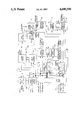
- Received video information is introduced into device 5 of this invention in conventional digital format (i.e., from a source such as a camera and/or computer generated video information, for example, providing conventional left to right serial readout of each scan line).
- a source such as a camera and/or computer generated video information, for example, providing conventional left to right serial readout of each scan line.
- Buffer memory unit 7 is at least a one line memory capable of receiving each scan line of received video information and coupling the same to storage memory unit 9 as a serial presentation thereto. This data base information is then latched into storage memory unit 9, which storage memory unit must have a capability of receiving and storing at least two complete scan lines so that as one line is being written into memory unit 9 from buffer unit 7, the inediately preceding line is being serially read out of memory unit 9.
- Sync processor 11 is connected with synchronizer network 13 to receive horizontal and vertical synchronized pulses therefron. Sync processor 11 performs the housekeeping function of line and field addressing, and pursuant thereto, provides a field address output on lead 15 and a line address output on lead 17, both of which are coupled to buffer memory unit 7 and to delay control network 19, which network is connected to storage memory unit 9 to control the readout therefrom.
- Delay control network 19 performs the function of reading out the storage memory unit in the proper order as needed (as brought out more fully hereinafter) and at the proper time with correct sequence based on the line and field addresses.
- Line and field address coding is also normally sent to a user for external monitoring, manipulation, etc. (as is a hand shake output from buffer unit 7), and such line and field addressing is also coupled on leads 21 and 22 to horizontal scan deflecting circuitry 23 and vertical scan deflecting circuitry 25, respectively, which units also receive line and field rate inputs from sync processor 11 on leads 26 and 27, respectively.
- delay control network 19 causes the first line and every other succeeding line thereafter (i.e., the odd numbered lines) occuring during each frame to be serially read out of memory unit 9 in the same order as written into memory unit 9 from buffer memory unit 7.
- delay control network 19 also causes the second line and every other succeeding line thereafter (i.e., the even numbered lines) occurring during each frame to be serially read out of memory unit 9 in reverse order as written into memory unit 9 from buffer memory unit 7.
- the first video line is received at buffer memory unit 7 and latched into storage memory unit 9.
- this line is latched into storage memory unit 9, and during this time, the first video line is read out of memory unit 9 in the same order as written into memory unit 9.
- the third line of video is serially presented to buffer memory unit 7.
- the second line of video (then stored in memory unit 9) is read out of storage memory unit 9 in reverse order with respect to the order the line was written into memory unit 9 (and hence in reverse order to the readout of the first video line from memory unit 9). This procedure is then continued throughout the frame.
- Each complete scan line read out from memory unit 9 is coupled through digital-to-analog (D/A) converter 29 (where utilized) and video amplifier 31 to the Z axis drive of raster scanned cathode ray tube (CRT) display 33.
- Amplifier 31 performs a final function of CRT-Z axis drive for beam intensity modulation.
- Converter 29 is utilized if the video is analog based in order to convert the incoming signal to an analog signal compatible for use as the analog input signal to a conventional raster scan cathode ray tube display. If the video is digitally based, converter 29 is not utilized and the output from storage memory unit 9 is coupled directly to amplifier 31.
- Vertical scan deflecting circuitry 25 includes a vertical step scan generator 35, a vertical deflection amplifier 37, and a vertical coil winding 39, with vertical position feedback being coupled from winding 39 to vertical step scan generator 35.
- vertical deflection amplifier 37 Based on the field address information sent to vertical step scan generator 35, vertical deflection amplifier 37 causes the cathode ray tube to start the display of the first line of video (which is normally scanned from left to right) at the upper left hand corner of the display.
- the step scan generator utilized in this invention generates a step function change in the vertical deflection (as indicated in the drawing) and avoids the horizontal scan tilt normally associated with raster scan displays.
- the vertical scan generator is readdressed for each field line.
- Horizontal scan deflecting circuitry 23 includes a horizontal scan generator 41, a horizontal deflection amplifier 43, and a horizontal coil winding 45, with horizontal position feedback being coupled from winding 45 to horizontal scan generator 41.
- Horizontal scan generator 41 performs the actual bidirectional sweep task along each scan line after the beam has been addressed vertically to the top of the cathode ray tube.
- the positive scan slope moves the beam from left to right. This scanning direction is synchronized with the presentation of each odd numbered line of video information.
- the negative scan slope (also indicated in the drawing) reverses the beam direction from right to left.
- the negative sweep deflection is associated with the presentation of video information on each even numbered line. This alternating horizontal scan cycle process is then repeated throughout the frame until all raster lines are displayed to the point of frame refresh.
- deflection power is conserved by utilizing energy already developed in the horizontal winding at the end of each scan line. Fast horizontal beam retrace is no longer needed, and this results in a reduction in power supply costs. Thus, deflection power is no longer lost to beam retrace and deflection components switching losses, and lower horizontal deflection supply voltage levels now result.
- Error correction is also provided for both horizontal scan deflection circuitry 23 and the vertical scan deflection scan circuitry 25.
- horizontal geometric profiler 47 receives a programmable correction input and provide outputs (least significant bit to most significant bit) to geometric error corrector 49 connected between horizontal scan generator 41 and horizontal deflection amplifier 43.
- vertical geometric profiler 51 receives a programmable correction input and provides outputs (least significant bit to most significant bit) to geometric error corrector 53 connected between the vertical step scan generator 35 and vertical deflection amplifier 37.
- Both the horizontal and vertical error corrections are derived by measurements extrapolated from the front face of the CRT displayed pattern. Deflection non-linearity or errors are recorded to determine the deviations of the display pattern geometry from the desired geometry. This recorded deviance can then be fit to a mathematical expression or algorithm which then becomes the programmable corrective input.
- the encoding of such information into digital memory can be accomplished by storage elements such as a programmable read only menory (PROM) chip.
- PROM programmable read only menory
- the stored data reflects the necessary corrective weighting function to be applied to the horizontal and vertical scan signals to modify the deflection, thereby providing the correct geometric profile to minimize deflection non-linearity and/or display pertibations or errors.
- the geometric profilers calibrate out CRT/Yoke deficiencies for a given display to achive geometric pattern integrity patterned for each CRT display manufactured. Since the algorithms developed are made a function of the raster line and field address, the geometric profilers provide a medium to maintain display geometry performance relatively independent of the operating line and field scan rates.
- test pattern unit 55 governing display positional accuracy, is utilized to provide user feedback with which to manipulate the display geometric performance attributes by programmable corrective inputs to correctors 49 and 53. As shown in the drawing, test pattern unit 55 receives the field and line addresses on lines 15 and 17, respectively.
- Another inherent design advantage of this invention allows an interlaced display operation to occur with superior scan registration because of less susceptibility to input signal scan noise, compared to the standard analog technique.
- each complete line of video information is coupled to buffer memory unit 7 and then latched into storage memory unit 9.
- the preceding line is then serially read out of storage memory unit 9 (as the next following line is being read into memory storage unit 9) and coupled through the coupling circuitry (digital-to-analog converter 29, if utilized, and video amplifier 31) to the cathode ray tube for display by modulating the beam intensity.
- the readout is caused to be in the same order as written into memory unit 9, and for each even numbered line, the readout is caused to be in reverse order as written into memory unit 9.
- the horizontal scan deflection unit is caused to deflect the beam from left to right (when the incoming video information is conventional with left to right readout of the camera originating the video information).
- the horizontal scan deflection unit is caused to deflect the beam from right to left (where the incoming video information is conventional with right to left readout of the camera originating the video information).
- Each line of each frame is then scanned with odd numbered lines being scanned left to right and even numbered lines being scanned from left to right, with each line being selected for scanning by the vertical step scan generator.
- the invention provides a device and method for bidirectional scanning of a cathode ray tube display without loss of intelligibility of received video information.
Landscapes
- Engineering & Computer Science (AREA)
- Multimedia (AREA)
- Signal Processing (AREA)
- Details Of Television Scanning (AREA)
- Controls And Circuits For Display Device (AREA)
- Television Systems (AREA)
Priority Applications (4)
| Application Number | Priority Date | Filing Date | Title |
|---|---|---|---|
| US06/728,387 US4680599A (en) | 1985-04-29 | 1985-04-29 | Cathode ray tube display system and method having bidirectional line scanning |
| CA000506102A CA1250975A (en) | 1985-04-29 | 1986-04-08 | Cathode ray tube display system and method having bidirectional line scanning |
| EP86105387A EP0200116A3 (de) | 1985-04-29 | 1986-04-18 | Kathodenstrahlröhrensichtgerät und Verfahren zur doppelgerichteten Zeilenabtastung |
| JP61097051A JPS61263371A (ja) | 1985-04-29 | 1986-04-28 | 陰極線管の両方向走査方法および両方向走査表示システム |
Applications Claiming Priority (1)
| Application Number | Priority Date | Filing Date | Title |
|---|---|---|---|
| US06/728,387 US4680599A (en) | 1985-04-29 | 1985-04-29 | Cathode ray tube display system and method having bidirectional line scanning |
Publications (1)
| Publication Number | Publication Date |
|---|---|
| US4680599A true US4680599A (en) | 1987-07-14 |
Family
ID=24926646
Family Applications (1)
| Application Number | Title | Priority Date | Filing Date |
|---|---|---|---|
| US06/728,387 Expired - Fee Related US4680599A (en) | 1985-04-29 | 1985-04-29 | Cathode ray tube display system and method having bidirectional line scanning |
Country Status (4)
| Country | Link |
|---|---|
| US (1) | US4680599A (de) |
| EP (1) | EP0200116A3 (de) |
| JP (1) | JPS61263371A (de) |
| CA (1) | CA1250975A (de) |
Cited By (13)
| Publication number | Priority date | Publication date | Assignee | Title |
|---|---|---|---|---|
| US4956585A (en) * | 1987-04-02 | 1990-09-11 | Deutsche Thomson-Brandt Gmbh | Line deflection circuit for a picture tube |
| US4988927A (en) * | 1988-09-14 | 1991-01-29 | Deutsche Thomson-Brandt Gmbh | Deflection circuit for a television picture tube |
| US4991023A (en) * | 1989-05-22 | 1991-02-05 | Hewlett-Packard Company | Microprocessor controlled universal video monitor |
| US6031557A (en) * | 1998-07-17 | 2000-02-29 | Sienna Imaging, Inc. | Bi-directional sweeping for color CRT printers |
| US6034709A (en) * | 1998-07-17 | 2000-03-07 | Sienna Imaging Inc. | Bi-directional sweeping for monochrome CRT printers |
| US6281947B1 (en) | 1997-03-21 | 2001-08-28 | Corning Incorporated | Mask-free, single gun, color television systems |
| US20020140818A1 (en) * | 2001-04-02 | 2002-10-03 | Pelco | System and method for generating raster video test patterns |
| WO2004004315A1 (en) * | 2002-06-27 | 2004-01-08 | Silicon Light Machines Corporation | Triangular bidirectional scan method for projection display |
| US6690339B2 (en) * | 1998-12-07 | 2004-02-10 | Siemens Aktiengesellschaft | Method and circuit arrangement for controlling the operating point of a cathode ray tube |
| US6839055B1 (en) | 2000-01-25 | 2005-01-04 | Dell Products L.P. | Video data error detection |
| US20050174071A1 (en) * | 2002-04-04 | 2005-08-11 | Simpson Theodore F. | Transposed bi-directional scanning in a cathode ray tube |
| US7830391B2 (en) | 2001-02-15 | 2010-11-09 | Sony Corporation | Checkerboard buffer using two-dimensional buffer pages |
| US20140285483A1 (en) * | 2013-03-25 | 2014-09-25 | Sony Corporation | Image processing apparatus, image processing method, and program |
Families Citing this family (4)
| Publication number | Priority date | Publication date | Assignee | Title |
|---|---|---|---|---|
| DE59309505D1 (de) * | 1992-02-20 | 1999-05-20 | Thomson Brandt Gmbh | Ablenkschaltung für einen Fernsehempfänger mit symmetrischer Ablenkung |
| DE4207350A1 (de) * | 1992-03-07 | 1993-09-09 | Thomson Brandt Gmbh | Ablenkschaltung fuer einen fernsehempfaenger mit symmetrischer ablenkung |
| FR2696306A1 (fr) * | 1992-09-29 | 1994-04-01 | Nokia Consumer Electronics Fra | Dispositif de pilotage d'un déviateur de faisceaux de balayage d'un écran d'un moniteur notamment de télévision à haute définition et moniteur comportant un tel dispositif. |
| GB2323232A (en) * | 1997-03-12 | 1998-09-16 | Alexander Laurence Paterson | Boustrophedal image display generation |
Citations (9)
| Publication number | Priority date | Publication date | Assignee | Title |
|---|---|---|---|---|
| US2717329A (en) * | 1950-09-19 | 1955-09-06 | Westinghouse Electric Corp | Television scan system |
| US3145378A (en) * | 1960-03-30 | 1964-08-18 | Jr William F Lyons | Retrace insertion system |
| US3164822A (en) * | 1960-08-29 | 1965-01-05 | Frank B Uphoff | Diode wave form generator for symbol generation during the retrace interval of a cathode ray tube |
| US3662102A (en) * | 1970-09-15 | 1972-05-09 | Us Navy | Bi-directional television scan system |
| US3757038A (en) * | 1969-09-04 | 1973-09-04 | Time Inc | Image analyzing apparatus |
| US3938105A (en) * | 1974-06-24 | 1976-02-10 | Honeywell Information Systems Inc. | Sequentially encoded data structures that support bidirectional scanning |
| US4203102A (en) * | 1977-11-16 | 1980-05-13 | International Business Machines Corporation | Character display system |
| US4205310A (en) * | 1978-05-22 | 1980-05-27 | Thomson-Csf Laboratories, Inc. | Television titling apparatus and method |
| US4491835A (en) * | 1982-03-24 | 1985-01-01 | Allied Corporation | Raster and stroke writing deflection amplifier arrangement |
Family Cites Families (9)
| Publication number | Priority date | Publication date | Assignee | Title |
|---|---|---|---|---|
| JPS5176930A (ja) * | 1974-12-27 | 1976-07-03 | Hitachi Ltd | Hyojisochi |
| JPS5176931A (ja) * | 1974-12-27 | 1976-07-03 | Hitachi Ltd | Mojihyojisochi |
| JPS53133333A (en) * | 1977-04-27 | 1978-11-21 | Toshiba Corp | Scanning system |
| DE2808224A1 (de) * | 1978-02-25 | 1979-09-06 | Koerting Radio Werke Gmbh | Energiesparendes zeilen- und bild- ablenkverfahren an einem sequentiellen fernseh-bildaufnahme- und wiedergabesystem |
| JPS56138785A (en) * | 1980-03-31 | 1981-10-29 | Shimadzu Corp | X-y monitor |
| JPS57211189A (en) * | 1981-06-23 | 1982-12-24 | Casio Computer Co Ltd | Crt display controller |
| GB2137844B (en) * | 1983-03-14 | 1987-03-25 | British Broadcasting Corp | Scan conversion circuit |
| JPS6070486A (ja) * | 1983-09-28 | 1985-04-22 | 株式会社日立製作所 | Crt画像表示装置 |
| JPS6093482A (ja) * | 1983-10-27 | 1985-05-25 | 富士通株式会社 | 表示装置 |
-
1985
- 1985-04-29 US US06/728,387 patent/US4680599A/en not_active Expired - Fee Related
-
1986
- 1986-04-08 CA CA000506102A patent/CA1250975A/en not_active Expired
- 1986-04-18 EP EP86105387A patent/EP0200116A3/de not_active Withdrawn
- 1986-04-28 JP JP61097051A patent/JPS61263371A/ja active Pending
Patent Citations (9)
| Publication number | Priority date | Publication date | Assignee | Title |
|---|---|---|---|---|
| US2717329A (en) * | 1950-09-19 | 1955-09-06 | Westinghouse Electric Corp | Television scan system |
| US3145378A (en) * | 1960-03-30 | 1964-08-18 | Jr William F Lyons | Retrace insertion system |
| US3164822A (en) * | 1960-08-29 | 1965-01-05 | Frank B Uphoff | Diode wave form generator for symbol generation during the retrace interval of a cathode ray tube |
| US3757038A (en) * | 1969-09-04 | 1973-09-04 | Time Inc | Image analyzing apparatus |
| US3662102A (en) * | 1970-09-15 | 1972-05-09 | Us Navy | Bi-directional television scan system |
| US3938105A (en) * | 1974-06-24 | 1976-02-10 | Honeywell Information Systems Inc. | Sequentially encoded data structures that support bidirectional scanning |
| US4203102A (en) * | 1977-11-16 | 1980-05-13 | International Business Machines Corporation | Character display system |
| US4205310A (en) * | 1978-05-22 | 1980-05-27 | Thomson-Csf Laboratories, Inc. | Television titling apparatus and method |
| US4491835A (en) * | 1982-03-24 | 1985-01-01 | Allied Corporation | Raster and stroke writing deflection amplifier arrangement |
Cited By (17)
| Publication number | Priority date | Publication date | Assignee | Title |
|---|---|---|---|---|
| US4956585A (en) * | 1987-04-02 | 1990-09-11 | Deutsche Thomson-Brandt Gmbh | Line deflection circuit for a picture tube |
| US4988927A (en) * | 1988-09-14 | 1991-01-29 | Deutsche Thomson-Brandt Gmbh | Deflection circuit for a television picture tube |
| US4991023A (en) * | 1989-05-22 | 1991-02-05 | Hewlett-Packard Company | Microprocessor controlled universal video monitor |
| US6281947B1 (en) | 1997-03-21 | 2001-08-28 | Corning Incorporated | Mask-free, single gun, color television systems |
| US6031557A (en) * | 1998-07-17 | 2000-02-29 | Sienna Imaging, Inc. | Bi-directional sweeping for color CRT printers |
| US6034709A (en) * | 1998-07-17 | 2000-03-07 | Sienna Imaging Inc. | Bi-directional sweeping for monochrome CRT printers |
| WO2000016368A1 (en) * | 1998-09-14 | 2000-03-23 | Sienna Imaging, Inc. | Bi-directional sweeping for color crt printers |
| US6690339B2 (en) * | 1998-12-07 | 2004-02-10 | Siemens Aktiengesellschaft | Method and circuit arrangement for controlling the operating point of a cathode ray tube |
| US6839055B1 (en) | 2000-01-25 | 2005-01-04 | Dell Products L.P. | Video data error detection |
| US7830391B2 (en) | 2001-02-15 | 2010-11-09 | Sony Corporation | Checkerboard buffer using two-dimensional buffer pages |
| US20020140818A1 (en) * | 2001-04-02 | 2002-10-03 | Pelco | System and method for generating raster video test patterns |
| US20050174071A1 (en) * | 2002-04-04 | 2005-08-11 | Simpson Theodore F. | Transposed bi-directional scanning in a cathode ray tube |
| US20040165069A1 (en) * | 2002-06-27 | 2004-08-26 | Webb Douglas A. | Triangular bidirectional scan method for projection display |
| US7053930B2 (en) | 2002-06-27 | 2006-05-30 | Silicon Light Machines Corporation | Triangular bidirectional scan method for projection display |
| WO2004004315A1 (en) * | 2002-06-27 | 2004-01-08 | Silicon Light Machines Corporation | Triangular bidirectional scan method for projection display |
| US20140285483A1 (en) * | 2013-03-25 | 2014-09-25 | Sony Corporation | Image processing apparatus, image processing method, and program |
| US9454794B2 (en) * | 2013-03-25 | 2016-09-27 | Sony Corporation | Image processing apparatus, image processing method, and program |
Also Published As
| Publication number | Publication date |
|---|---|
| JPS61263371A (ja) | 1986-11-21 |
| EP0200116A2 (de) | 1986-11-05 |
| CA1250975A (en) | 1989-03-07 |
| EP0200116A3 (de) | 1988-06-08 |
Similar Documents
| Publication | Publication Date | Title |
|---|---|---|
| US4680599A (en) | Cathode ray tube display system and method having bidirectional line scanning | |
| US4099092A (en) | Television display alignment system and method | |
| US3396377A (en) | Display data processor | |
| RU2108686C1 (ru) | Система управления сведением для множества вертикальных форматов | |
| KR100307108B1 (ko) | 투사텔레비젼에서레지스트레이션조정을향상하는보간방법및장치 | |
| EP0420568B1 (de) | Digitale Konvergenzvorrichtung | |
| US4687973A (en) | Digital waveform generator | |
| JPS6227710B2 (de) | ||
| US4992706A (en) | CRT raster distortion correction circuit | |
| EP0561043B1 (de) | Kissenverzeichnungskorrekturschaltung für den oberen/unteren Teil | |
| JPH0225594B2 (de) | ||
| US6525778B1 (en) | Image display unit for displaying undistorted images having different aspect ratios | |
| US5013978A (en) | Compensation arrangement for display systems | |
| WO1991003130A1 (en) | Convergence control system | |
| EP0110282A1 (de) | Verfahren und Schaltungsanordnung zur Korrektur der Bildverzerrung | |
| JP2005165346A (ja) | マトリクスディスプレイの制御装置 | |
| JP2822469B2 (ja) | テレビ受像機 | |
| KR100387000B1 (ko) | 화상 표시 장치 및 수평 속도 변조 장치 | |
| GB2101459A (en) | Television display correction | |
| JPS6163177A (ja) | デイジタルコンバ−ゼンス装置 | |
| JPH0750936B2 (ja) | デイジタルコンバ−ゼンス装置 | |
| JPH0583719A (ja) | デイジタルダイナミツクコンバーゼンス装置 | |
| JPH0514912A (ja) | デイジタルコンバーゼンス装置 | |
| SU813498A1 (ru) | Устройство дл отображени информа-ции HA эКРАНЕ элЕКТРОННО-лучЕВОйТРубКи | |
| JPH11122562A (ja) | 画像補正装置 |
Legal Events
| Date | Code | Title | Description |
|---|---|---|---|
| AS | Assignment |
Owner name: BALL CORPORATION, 345 SOUTH HIGH STREET, MUNCIE, I Free format text: ASSIGNMENT OF ASSIGNORS INTEREST.;ASSIGNORS:WERTZ, RONALD D.;ORSZULAK, JAMES H.;SWEENEY, CHRISTOPHER L.;REEL/FRAME:004402/0945 Effective date: 19850416 |
|
| FEPP | Fee payment procedure |
Free format text: PAYOR NUMBER ASSIGNED (ORIGINAL EVENT CODE: ASPN); ENTITY STATUS OF PATENT OWNER: LARGE ENTITY |
|
| FPAY | Fee payment |
Year of fee payment: 4 |
|
| AS | Assignment |
Owner name: ALLTRISTA CORPORATION, INDIANA Free format text: ASSIGNMENT OF ASSIGNORS INTEREST;ASSIGNOR:BALL CORPORATION;REEL/FRAME:006622/0001 Effective date: 19930402 |
|
| AS | Assignment |
Owner name: BALL CORPORATION, INDIANA Free format text: ASSIGNMENT OF ASSIGNORS INTEREST;ASSIGNOR:ALLTRISTA CORPORATION;REEL/FRAME:006942/0875 Effective date: 19940404 |
|
| REMI | Maintenance fee reminder mailed | ||
| LAPS | Lapse for failure to pay maintenance fees | ||
| FP | Lapsed due to failure to pay maintenance fee |
Effective date: 19950719 |
|
| STCH | Information on status: patent discontinuation |
Free format text: PATENT EXPIRED DUE TO NONPAYMENT OF MAINTENANCE FEES UNDER 37 CFR 1.362 |