US4638663A - Level indicating device for liquid containers - Google Patents
Level indicating device for liquid containers Download PDFInfo
- Publication number
- US4638663A US4638663A US06/807,809 US80780985A US4638663A US 4638663 A US4638663 A US 4638663A US 80780985 A US80780985 A US 80780985A US 4638663 A US4638663 A US 4638663A
- Authority
- US
- United States
- Prior art keywords
- container
- indicating device
- level indicating
- union
- piston
- Prior art date
- Legal status (The legal status is an assumption and is not a legal conclusion. Google has not performed a legal analysis and makes no representation as to the accuracy of the status listed.)
- Expired - Fee Related
Links
Images


Classifications
-
- G—PHYSICS
- G01—MEASURING; TESTING
- G01F—MEASURING VOLUME, VOLUME FLOW, MASS FLOW OR LIQUID LEVEL; METERING BY VOLUME
- G01F23/00—Indicating or measuring liquid level or level of fluent solid material, e.g. indicating in terms of volume or indicating by means of an alarm
- G01F23/30—Indicating or measuring liquid level or level of fluent solid material, e.g. indicating in terms of volume or indicating by means of an alarm by floats
- G01F23/303—Indicating or measuring liquid level or level of fluent solid material, e.g. indicating in terms of volume or indicating by means of an alarm by floats characterised by means to prevent fault-level readings due to turbulence of the fluid, e.g. special float housings
-
- G—PHYSICS
- G01—MEASURING; TESTING
- G01F—MEASURING VOLUME, VOLUME FLOW, MASS FLOW OR LIQUID LEVEL; METERING BY VOLUME
- G01F23/00—Indicating or measuring liquid level or level of fluent solid material, e.g. indicating in terms of volume or indicating by means of an alarm
- G01F23/30—Indicating or measuring liquid level or level of fluent solid material, e.g. indicating in terms of volume or indicating by means of an alarm by floats
- G01F23/32—Indicating or measuring liquid level or level of fluent solid material, e.g. indicating in terms of volume or indicating by means of an alarm by floats using rotatable arms or other pivotable transmission elements
Definitions
- the present invention relates to a level indicating device for containers holding liquids having a floating sensing element operatively connected with a signal device.
- Level indicating devices generally have a float arranged on a lever arm which is deflected in the container as the liquid level in the container rises or falls. This deflection in turn acts on a signal device, which, for example, may be an optical indicating device or a measuring device with a scale or the like. Also, the signal device may be designed in such a way that the indication responds only to preset limit values of the liquid content of a container, for example to a minimum volume of the liquid in the container.
- float of a level indicating device can be placed relatively accurately in the center of the container, such false level indications as described above will rarely occur when the tilt of the level of the liquid in the container changes.
- arranging a float in the center of a container cannot be done, particularly when such fluid containers are divided into compartments by separating walls, such as baffles, or when the container has an asymmetric shape.
- separating walls and similar installed elements as well as asymmetric shapes are quite commonly found particularly in brake fluid receptacles for motor vehicles and in fuel tanks. Therefore, floats installed in such containers must necessarily be installed in a decentralized position and accordingly indicate false or invalid fluid levels when the vehicle or container is in a tilted position.
- the object of the present invention to provide a level indicating device for liquid containers which cannot accommodate a float disposed in the center thereof, such that false or invalid fluid level readings do not occur, particularly when the container is in a tilted position.
- a sensing element having several and preferably three floats arranged on a single plane. These floats are supported on lever arms which are interconnected at a centrally disposed union or joint. This union is supported for free movement in a guide disposed approximately in the center of the container and aligned approximately perpendicularly or vertically with respect to the surface of the fluid when the fluid is in the resting position.
- any change in tilt of the surface of the fluid has no influence on the joint or union of the lever arms, which is disposed for free movement in the center of the container.
- the lever arm union or joint can be operatively connected with the signal device. In this way, tilted positions of the container and the like, which change the tilt of the surface of the fluid in the container, are compensated for, so that false or invalid fluid level readings do not occur.
- the design according to the present invention i.e., of the sensing element with a plurality of floats connected in a central union or joint, is particularly suitable for a level indicating device for containers which do not permit a central arrangement of a float due to installations such as separating walls and the like.
- the guide for the lever arm union is designed in such a way that it maintains the lever arm union in free movement in the center of the container.
- a transmitting element can be connected with the union and operatively connected with the signal device.
- the transmitting element is disposed in such a way that the signal device is influenced only by movement of the lever arm union along the directed guide. Pivoting movements of the lever arms around the union, for example when the tilt of the fluid level in the container changes, have no effect on the transmitting element.
- a hollow cylinder arranged in the container is provided as the guide. If, for example, a container for brake fluid is provided with separating walls, such a hollow cylinder can be readily integrated in one of the separating walls, or arranged in the center of a container in some other way.
- the hollow cylinder which guides the lever arm union is aligned in such a way that its longitudinal axis extends perpendicularly or vertically with respect to the level of the liquid in the rest position.
- the union is capable of freely rotating in the hollow cylinder following the tilting or swivelling movement of the floats and their lever arms caused by the changing tilt of the surface of the fluid.
- the union is adapted to only slide up and down in the longitudinal direction of the hollow cylinder.
- the wall of the hollow cylinder is provided with longitudinal slots, with a lever arm extending through each slot.
- an interconnection between the lever arm union and the transmitting element, in order to permit a controlled transmission of the motion of the union is designed in such a way that the union is in the form of a ball joint guided in the hollow cylinder and having a clearance or recess therein in the form of a socket joint, and the transmitting element includes a ball bearing supported in this socket joint.
- the socket of the ball joint and the ball bearing received therein prevent that pivoting or rotating motions of the union and thus of the socket, which motions are caused by changes in the tilt of the fluid level in the container by way of the floats, from being transmitted to the transmitting element.
- the socket freely rotates on the ball bearing.
- the socket of the lever arm union and the ball bearing associated therewith are capable of being lockingly engaged with each other by means of a snap connection.
- Such an assemblage facilitates the installation of the ball and socket.
- the components may be manufactured from plastic material by injection molding. This results in the advantage that a relatively high dimensional accuracy can be maintained, which is very important to assure smoothness of motion between the socket and ball as well as to assure the desired solid and firm seating of the locked snap connection.
- the transmitting element be a piston guided in the hollow cylinder and having a piston rod with the ball bearing mounted on the free end of the rod. Lifting and lowering motions of the central union of the floats within the guide provided in the form of a hollow cylinder thus effect a motion of the piston which, also, is preferably guided in the hollow cylinder.
- the piston may act on the signal device by having embedded therein a permanent magnet and the signal device may have a reed contact associated with the piston travel.
- this type of transmission of a change in level of the fluid in a container is particularly useful for brake fluid receptacles for motor vehicles, because such receptacles are normally made of plastic material.
- the magnetic field of the permanent magnet installed in the piston may penetrate walls, for example the wall of the hollow cylinder serving as the guide, or the separating walls or the outside walls of the container, which means that the reed contact may also be arranged outside of the container.
- the reed contact may be inserted in a hollow chamber of the container, which is accessible from the outside thereof.
- This arrangement has the advantage that the reed contact and thus the transmitting elements for transmission to the indicator and signal device do not in any way come into contact with the fluid contained in the container.
- receptacles made of plastic material, for example brake fluid containers such a hollow chamber or compartment can be readily shaped when such a container is molded, and the reed contact inserted and secured in the chamber like a cartridge, with the wires for the connection to a signal and indicating device, which, for example, may be instruments mounted on the dashboard of a motor vehicle, extending from the hollow chamber or compartment.
- a control pin associated with the lever arm union which projects from the hollow cylinder and protrudes from the container through an opening in the container.
- the control pin may extend up to beneath the lid or cover covering the filler tube of the fluid container.
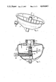
- FIG. 1 is a side elevational view of a brake fluid container for motor vehicles
- FIG. 2 is a cross-sectional view taken along line II--II of FIG. 1 showing the level indicating device of the present invention
- FIG. 3 is a cross-sectional view taken along line III--III of FIG. 2;
- FIG. 4 is a perspective side view of the bottom part of the container of FIG. 1;
- FIG. 5 is a cross-sectional view of the container of FIG. 1 similar to the view of FIG. 2 but turned 90° thereto.
- FIG. 1 a brake fluid container, designated 1, for motor vehicles.
- the container is made of plastic material and comprised of a bottom part 2 with fluid connections 3 on the bottom, and a top part 4 with a filler neck 5 adapted to be closed by means of a screw cap 6.
- Bottom part 2 and top part 4 are connected with each other by means of collar flanges 7.
- Bottom part 2 is provided with an external plug contact 38 for connecting the container to the indicating elements of a signal device such as measuring instruments or the like, which are not shown.
- the interior of container 1 is subdivided by a separating wall 8 extending approximately through the center of the container, so that a central float serving as the sensing element could not be arranged therein.
- the sensing element therefore, consists of three floats, of which only floats 9 and 10 are visible in FIG. 2. These floats are mounted on the ends of lever arms which converge in the center of the container and which are interconnected with each other. Only lever arms 11 and 12, having floats 9 and 10, respectively, mounted thereon, are visible in this figure.
- the central interconnection of the lever arms forms a junction or a center union 13 which, in the present embodiment, is provided in the form of a socket joint 14.
- a guide 15 is integrated in separating wall 8 and in the present embodiment is provided in the form of a hollow cylinder 16.
- the wall of hollow cylinder 16 is provided with longitudinal slots 17 (see FIG. 4).
- Each longitudinal slot is associated with a lever arm guiding its respective float, and each lever arm extends through the associated slot.
- guide 15 shaped as a hollow cylinder 16 in the center of the container. Since the floats are capable of free movement in guide 15 by means of union 13 provided in the form of socket joint 14, any change in inclination or tilt of surface 18 of the fluid in the container has no effect on the vertical motion of union 13, such motion taking place only in the longitudinal direction of hollow cylinder 16.
- the dashed lines of levers 11 and 12 and their respective floats 9 and 10 indicate a position of the floats with the container in a tilted position.
- a transmitting element, designated 19, is provided in the form of a piston 20.
- Piston 20 is guided with relative stability against tilting and thus free from jamming and is provided with a piston rod 21.
- a ball bearing 22 is seated at the free end of piston rod 21 and is inserted in the socket joint 14 of union 13 by means of a snap connection. Thus, ball bearing 22 is locked in socket 14 by the snap connection.
- a permanent magnet 23 is embedded in piston 20.
- a hollow compartment 24 is formed at the bottom of the hollow cylinder, the compartment being accessible from outside of the container.
- Filler neck 5 in top part 4 of the container is provided with an inserted mounting support 26 guiding a control pin 27 having a tip 28 resting on union 13.
- the function and operational safety of the level indicating device can be checked and controlled by manually depressing control pin 27, since reed contact 25 inserted in hollow compartment 24 responds when approached by permanent magnet 23 embedded in piston 20. Normally, this response is initiated when level 18 of the fluid in the container drops, followed by the floats. However, as described above, such response can be simulated by depressing control pin 27 by hand.
- FIG. 3 clearly shows how the three floats 9, 10 and 9a are supported in the center union 13 disposed between lever arms 11, 12 and 12a.
- the lever arms form between each other an angle of about 120 degrees.
- This junction in turn is supported for free movement in guide 15 provided in the form of hollow cylinder 16, guide 15 being integrated in separating wall 8 of the container.
- Separating wall 8 divides the interior space of the container into two compartments connected with each other by means of an overflow slot 29 provided in the separating wall. In this way, the fluid content of the container is capable of flowing from one compartment into the other. Consequently, the level of the surface of the fluid is always the same in the two compartments.
- FIG. 4 clearly shows that arrangement of separating wall 8 and guide 15 having the form of a hollow cylinder 16.
- Hollow cylinder 16 has longitudinal slots 17, 17' and 17", which are suggested also in FIG. 2.
- Reference numeral 29 identifies the overflow slot provided in the separating wall 8.
- FIG. 5 is a cross-sectional view of the container of FIG. 1, taken along a plane parallel to the plane of the drawing.
- the floats with their lever arms shown in FIGS. 2 and 3 are not shown in FIG. 5 in order to allow for a clearer view.
- FIG. 5 clearly illustrates the outwardly extending hollow compartment 24 with a reed contact 25 inserted therein and wired with plug contact 38.
Landscapes
- Physics & Mathematics (AREA)
- Fluid Mechanics (AREA)
- General Physics & Mathematics (AREA)
- Level Indicators Using A Float (AREA)
- Details Of Rigid Or Semi-Rigid Containers (AREA)
- Transmission Of Braking Force In Braking Systems (AREA)
Applications Claiming Priority (2)
| Application Number | Priority Date | Filing Date | Title |
|---|---|---|---|
| DE19843445475 DE3445475A1 (de) | 1984-12-13 | 1984-12-13 | Fuellstandsanzeige fuer fluessigkeitsbehaelter |
| DE3445475 | 1984-12-13 |
Publications (1)
| Publication Number | Publication Date |
|---|---|
| US4638663A true US4638663A (en) | 1987-01-27 |
Family
ID=6252673
Family Applications (1)
| Application Number | Title | Priority Date | Filing Date |
|---|---|---|---|
| US06/807,809 Expired - Fee Related US4638663A (en) | 1984-12-13 | 1985-12-11 | Level indicating device for liquid containers |
Country Status (4)
| Country | Link |
|---|---|
| US (1) | US4638663A (de) |
| EP (1) | EP0184687A3 (de) |
| JP (1) | JPS61203346A (de) |
| DE (1) | DE3445475A1 (de) |
Cited By (5)
| Publication number | Priority date | Publication date | Assignee | Title |
|---|---|---|---|---|
| US4840137A (en) * | 1987-07-01 | 1989-06-20 | Casco Products Corporation | Liquid level gauging apparatus |
| US5026954A (en) * | 1989-10-16 | 1991-06-25 | Hi-Stat Manufacturing Co., Inc. | Liquid level sensing switch assembly |
| US5279157A (en) * | 1992-08-03 | 1994-01-18 | Casco Products Corporation | Liquid level monitor |
| KR101240930B1 (ko) * | 2006-06-26 | 2013-03-08 | 현대자동차주식회사 | 자동차용 연료탱크 |
| US20140345977A1 (en) * | 2013-05-24 | 2014-11-27 | GM Global Technology Operations LLC | Fluid level detection device with stabilizer |
Families Citing this family (7)
| Publication number | Priority date | Publication date | Assignee | Title |
|---|---|---|---|---|
| IT1211347B (it) * | 1987-07-31 | 1989-10-18 | Fiat Auto Spa | Dispositivo di misura del quantitativo di liquido contenuto all interno di un serbatoio |
| FR2627583B1 (fr) * | 1988-02-18 | 1992-01-31 | Peugeot | Dispositif de mesure du niveau d'un liquide dans un reservoir notamment de vehicule automobile |
| FR2658909B1 (fr) * | 1990-02-23 | 1992-06-19 | Peugeot | Dispositif de mesure du niveau d'un liquide dans un reservoir notamment de vehicule automobile. |
| JP3166196B2 (ja) * | 1991-04-26 | 2001-05-14 | アイシン精機株式会社 | 液体リザーバ |
| DE19709738A1 (de) * | 1997-03-10 | 1998-09-17 | Bosch Gmbh Robert | Meßvorrichtung für den Füllstand eines Flüssigkeitsbehälters |
| DE10155085B4 (de) * | 2001-11-09 | 2011-07-21 | BSH Bosch und Siemens Hausgeräte GmbH, 81739 | Haushaltsgerät mit einem Flüssigkeitsbehälter und Füllstandsanzeige |
| GB2523816B (en) * | 2014-03-07 | 2018-11-21 | Jaguar Land Rover Ltd | Fuel level sensor apparatus and support structure therefor |
Citations (4)
| Publication number | Priority date | Publication date | Assignee | Title |
|---|---|---|---|---|
| US2939125A (en) * | 1957-10-11 | 1960-05-31 | William J Swanson | Tide indicator |
| US3935741A (en) * | 1973-08-15 | 1976-02-03 | Dresser Industries, Inc. | Level sensor |
| US4194396A (en) * | 1977-07-07 | 1980-03-25 | Nissan Shatai Co., Ltd. | Automobile fuel gauge system |
| US4500761A (en) * | 1982-06-01 | 1985-02-19 | Nissan Motor Company, Limited | Fluid reservoir with fluid-level sensor |
Family Cites Families (3)
| Publication number | Priority date | Publication date | Assignee | Title |
|---|---|---|---|---|
| DE2941347A1 (de) * | 1979-10-12 | 1981-04-23 | Vdo Adolf Schindling Ag, 6000 Frankfurt | Einrichtung zum messen des fuellstandes in grossbehaeltern |
| DE2944076A1 (de) * | 1979-10-31 | 1981-05-14 | Aral Ag, 4630 Bochum | Sonde |
| DE3124875C2 (de) * | 1981-06-25 | 1983-04-28 | Manfred Ing.(grad.) 4630 Bochum Templin | "Meßsonde" |
-
1984
- 1984-12-13 DE DE19843445475 patent/DE3445475A1/de not_active Withdrawn
-
1985
- 1985-11-16 EP EP85114599A patent/EP0184687A3/de not_active Withdrawn
- 1985-12-11 US US06/807,809 patent/US4638663A/en not_active Expired - Fee Related
- 1985-12-13 JP JP60279395A patent/JPS61203346A/ja active Pending
Patent Citations (4)
| Publication number | Priority date | Publication date | Assignee | Title |
|---|---|---|---|---|
| US2939125A (en) * | 1957-10-11 | 1960-05-31 | William J Swanson | Tide indicator |
| US3935741A (en) * | 1973-08-15 | 1976-02-03 | Dresser Industries, Inc. | Level sensor |
| US4194396A (en) * | 1977-07-07 | 1980-03-25 | Nissan Shatai Co., Ltd. | Automobile fuel gauge system |
| US4500761A (en) * | 1982-06-01 | 1985-02-19 | Nissan Motor Company, Limited | Fluid reservoir with fluid-level sensor |
Cited By (6)
| Publication number | Priority date | Publication date | Assignee | Title |
|---|---|---|---|---|
| US4840137A (en) * | 1987-07-01 | 1989-06-20 | Casco Products Corporation | Liquid level gauging apparatus |
| US5026954A (en) * | 1989-10-16 | 1991-06-25 | Hi-Stat Manufacturing Co., Inc. | Liquid level sensing switch assembly |
| US5279157A (en) * | 1992-08-03 | 1994-01-18 | Casco Products Corporation | Liquid level monitor |
| KR101240930B1 (ko) * | 2006-06-26 | 2013-03-08 | 현대자동차주식회사 | 자동차용 연료탱크 |
| US20140345977A1 (en) * | 2013-05-24 | 2014-11-27 | GM Global Technology Operations LLC | Fluid level detection device with stabilizer |
| US9175585B2 (en) * | 2013-05-24 | 2015-11-03 | GM Global Technology Operations LLC | Fluid level detection device with stabilizer |
Also Published As
| Publication number | Publication date |
|---|---|
| DE3445475A1 (de) | 1986-06-19 |
| EP0184687A2 (de) | 1986-06-18 |
| EP0184687A3 (de) | 1987-04-22 |
| JPS61203346A (ja) | 1986-09-09 |
Similar Documents
| Publication | Publication Date | Title |
|---|---|---|
| US4638663A (en) | Level indicating device for liquid containers | |
| US4532491A (en) | Liquid-level transmitter with bell jar housing for gasoline tanks | |
| US6408692B1 (en) | Liquid level sensor | |
| CA2137415C (en) | Remote indicating liquid level sensor | |
| US20100186246A1 (en) | Inclination sensor | |
| US3359799A (en) | Indicating device and method of filling containers | |
| WO2008047377A1 (en) | Fuel sender with reed switch and latching magnets | |
| US5333499A (en) | Liquid measuring float and float rod assembly | |
| US4194396A (en) | Automobile fuel gauge system | |
| US4442405A (en) | Float assembly for a sensor | |
| US4574631A (en) | Liquid level molded indicating gage portions | |
| US5435181A (en) | Electronic float gauge | |
| US4806902A (en) | Fluid level monitor and filler assembly | |
| EP0192282B1 (de) | Flüssigkeitszufuhrtank | |
| US7066024B2 (en) | Float adapted to track an interface between two liquids of differing density | |
| US3589191A (en) | Liquid level indicators | |
| WO2015132389A1 (en) | Fuel level sensor apparatus and support structure therefor | |
| EP0350185B1 (de) | Kraftstofftankschwimmer | |
| US4954724A (en) | Optical fuel gauge for vehicles | |
| US3726140A (en) | Liquid level indicating means | |
| US4752019A (en) | Combined dispensing head and level gauge | |
| EP0124401B1 (de) | Anzeiger für den Flüssigkeitsstand | |
| KR0168115B1 (ko) | 자동차 연료탱크의 연료량 측정장치 | |
| US3417615A (en) | Liquid level indicator | |
| JP3646701B2 (ja) | 液面計 |
Legal Events
| Date | Code | Title | Description |
|---|---|---|---|
| AS | Assignment |
Owner name: FIRMA RIESSELMANN & SOHN, BRANDSTRASSE, 2842 LOHNE Free format text: ASSIGNMENT OF ASSIGNORS INTEREST.;ASSIGNOR:SEELHORST, GOTTFRIED;REEL/FRAME:004495/0075 Effective date: 19851202 |
|
| REMI | Maintenance fee reminder mailed | ||
| LAPS | Lapse for failure to pay maintenance fees | ||
| STCH | Information on status: patent discontinuation |
Free format text: PATENT EXPIRED DUE TO NONPAYMENT OF MAINTENANCE FEES UNDER 37 CFR 1.362 |
|
| FP | Lapsed due to failure to pay maintenance fee |
Effective date: 19910127 |