US4588323A - Coupling device - Google Patents
Coupling device Download PDFInfo
- Publication number
- US4588323A US4588323A US06/572,576 US57257684A US4588323A US 4588323 A US4588323 A US 4588323A US 57257684 A US57257684 A US 57257684A US 4588323 A US4588323 A US 4588323A
- Authority
- US
- United States
- Prior art keywords
- drive shaft
- support arm
- coupling
- coupling device
- spring
- Prior art date
- Legal status (The legal status is an assumption and is not a legal conclusion. Google has not performed a legal analysis and makes no representation as to the accuracy of the status listed.)
- Expired - Fee Related
Links
- 230000008878 coupling Effects 0.000 title claims abstract description 63
- 238000010168 coupling process Methods 0.000 title claims abstract description 63
- 238000005859 coupling reaction Methods 0.000 title claims abstract description 63
- 238000004804 winding Methods 0.000 claims description 2
- 230000000295 complement effect Effects 0.000 claims 2
- 230000008901 benefit Effects 0.000 description 3
- 238000005452 bending Methods 0.000 description 2
- 230000000694 effects Effects 0.000 description 2
- 230000009471 action Effects 0.000 description 1
- 230000008859 change Effects 0.000 description 1
- 238000010276 construction Methods 0.000 description 1
- 230000007246 mechanism Effects 0.000 description 1
- 238000000034 method Methods 0.000 description 1
- 230000008569 process Effects 0.000 description 1
Images


Classifications
-
- F—MECHANICAL ENGINEERING; LIGHTING; HEATING; WEAPONS; BLASTING
- F16—ENGINEERING ELEMENTS AND UNITS; GENERAL MEASURES FOR PRODUCING AND MAINTAINING EFFECTIVE FUNCTIONING OF MACHINES OR INSTALLATIONS; THERMAL INSULATION IN GENERAL
- F16D—COUPLINGS FOR TRANSMITTING ROTATION; CLUTCHES; BRAKES
- F16D1/00—Couplings for rigidly connecting two coaxial shafts or other movable machine elements
- F16D1/10—Quick-acting couplings in which the parts are connected by simply bringing them together axially
-
- A—HUMAN NECESSITIES
- A01—AGRICULTURE; FORESTRY; ANIMAL HUSBANDRY; HUNTING; TRAPPING; FISHING
- A01B—SOIL WORKING IN AGRICULTURE OR FORESTRY; PARTS, DETAILS, OR ACCESSORIES OF AGRICULTURAL MACHINES OR IMPLEMENTS, IN GENERAL
- A01B71/00—Construction or arrangement of setting or adjusting mechanisms, of implement or tool drive or of power take-off; Means for protecting parts against dust, or the like; Adapting machine elements to or for agricultural purposes
- A01B71/06—Special adaptations of coupling means between power take-off and transmission shaft to the implement or machine
-
- F—MECHANICAL ENGINEERING; LIGHTING; HEATING; WEAPONS; BLASTING
- F16—ENGINEERING ELEMENTS AND UNITS; GENERAL MEASURES FOR PRODUCING AND MAINTAINING EFFECTIVE FUNCTIONING OF MACHINES OR INSTALLATIONS; THERMAL INSULATION IN GENERAL
- F16D—COUPLINGS FOR TRANSMITTING ROTATION; CLUTCHES; BRAKES
- F16D1/00—Couplings for rigidly connecting two coaxial shafts or other movable machine elements
- F16D1/10—Quick-acting couplings in which the parts are connected by simply bringing them together axially
- F16D1/101—Quick-acting couplings in which the parts are connected by simply bringing them together axially without axial retaining means rotating with the coupling
-
- F—MECHANICAL ENGINEERING; LIGHTING; HEATING; WEAPONS; BLASTING
- F16—ENGINEERING ELEMENTS AND UNITS; GENERAL MEASURES FOR PRODUCING AND MAINTAINING EFFECTIVE FUNCTIONING OF MACHINES OR INSTALLATIONS; THERMAL INSULATION IN GENERAL
- F16D—COUPLINGS FOR TRANSMITTING ROTATION; CLUTCHES; BRAKES
- F16D3/00—Yielding couplings, i.e. with means permitting movement between the connected parts during the drive
- F16D3/84—Shrouds, e.g. casings, covers; Sealing means specially adapted therefor
- F16D3/841—Open covers, e.g. guards for agricultural p.t.o. shafts
-
- F—MECHANICAL ENGINEERING; LIGHTING; HEATING; WEAPONS; BLASTING
- F16—ENGINEERING ELEMENTS AND UNITS; GENERAL MEASURES FOR PRODUCING AND MAINTAINING EFFECTIVE FUNCTIONING OF MACHINES OR INSTALLATIONS; THERMAL INSULATION IN GENERAL
- F16D—COUPLINGS FOR TRANSMITTING ROTATION; CLUTCHES; BRAKES
- F16D1/00—Couplings for rigidly connecting two coaxial shafts or other movable machine elements
- F16D1/10—Quick-acting couplings in which the parts are connected by simply bringing them together axially
- F16D2001/103—Quick-acting couplings in which the parts are connected by simply bringing them together axially the torque is transmitted via splined connections
-
- Y—GENERAL TAGGING OF NEW TECHNOLOGICAL DEVELOPMENTS; GENERAL TAGGING OF CROSS-SECTIONAL TECHNOLOGIES SPANNING OVER SEVERAL SECTIONS OF THE IPC; TECHNICAL SUBJECTS COVERED BY FORMER USPC CROSS-REFERENCE ART COLLECTIONS [XRACs] AND DIGESTS
- Y10—TECHNICAL SUBJECTS COVERED BY FORMER USPC
- Y10T—TECHNICAL SUBJECTS COVERED BY FORMER US CLASSIFICATION
- Y10T403/00—Joints and connections
- Y10T403/16—Joints and connections with adjunctive protector, broken parts retainer, repair, assembly or disassembly feature
- Y10T403/1608—Holding means or protector functioning only during transportation, assembly or disassembly
-
- Y—GENERAL TAGGING OF NEW TECHNOLOGICAL DEVELOPMENTS; GENERAL TAGGING OF CROSS-SECTIONAL TECHNOLOGIES SPANNING OVER SEVERAL SECTIONS OF THE IPC; TECHNICAL SUBJECTS COVERED BY FORMER USPC CROSS-REFERENCE ART COLLECTIONS [XRACs] AND DIGESTS
- Y10—TECHNICAL SUBJECTS COVERED BY FORMER USPC
- Y10T—TECHNICAL SUBJECTS COVERED BY FORMER US CLASSIFICATION
- Y10T403/00—Joints and connections
- Y10T403/59—Manually releaseable latch type
- Y10T403/591—Manually releaseable latch type having operating mechanism
- Y10T403/595—Lever
-
- Y—GENERAL TAGGING OF NEW TECHNOLOGICAL DEVELOPMENTS; GENERAL TAGGING OF CROSS-SECTIONAL TECHNOLOGIES SPANNING OVER SEVERAL SECTIONS OF THE IPC; TECHNICAL SUBJECTS COVERED BY FORMER USPC CROSS-REFERENCE ART COLLECTIONS [XRACs] AND DIGESTS
- Y10—TECHNICAL SUBJECTS COVERED BY FORMER USPC
- Y10T—TECHNICAL SUBJECTS COVERED BY FORMER US CLASSIFICATION
- Y10T403/00—Joints and connections
- Y10T403/70—Interfitted members
- Y10T403/7026—Longitudinally splined or fluted rod
- Y10T403/7031—Rod designed to be manipulable, e.g., twistable, within coupling for quick disconnect
Definitions
- the invention relates to a coupling device for connecting a drive shaft which forms a drive line for driving an agricultural implement or trailer through a tractor. More specifically, the invention relates to a coupling device consisting of a spring suspended drive shaft support wherein two coupling elements, axially lockable relative to each other and having a freewheeling device associated therewith, are adapted to be connected with each other to positively engage the drive shaft.
- a drive shaft coupler wherein both the drive shaft and the associated coupling device are attached to a fixed point in a spring suspended manner is known in the art in DE-OS No. 24 14 715.
- the rear of the tractor is provided with a hinged guiding part by means of which the drive shaft end to be coupled is guided towards the power take-off shaft.
- the present invention is intended to provide a coupling device which, after a single alignment operation relative to the respective tractor or implement, permits automatic recoupling of the drive shaft after, for example, a change of implement.
- the present invention may be described as a coupling device for connecting the drive shaft of an agricultural implement to a tractor comprising a supporting arm vertically pivotable around a first articulation point associated with the driven end of the drive shaft and designed as a fixed point connected to the free drive shaft end designed as a coupling sleeve, by means of a second articulation point and by means of a bearing.
- the two articulation points are each formed by a hinge which is tensioned in a friction locking manner by a spring and pivotable in the vertical direction.
- a pressure spring is arranged within the supporting arm formed of two profile tubes inserted into each other.
- the advantage of the coupling device in accordance with the invention is that after initial alignment of the free end of the drive shaft with respect to the tractor, the drive shaft, after disengagement, is held in a position which permits automatic recoupling simply by reversing the tractor. There is no need for the tractor driver to leave his seat or to ask for assistance.
- a further advantage is that, essentially, production drive shafts may be used, which merely require an outer joint yoke designed especially for the coupling operation.
- the second articulation point is arranged to be additionally swivable in the horizontal plane.
- This design is particularly advantageous if the drive shaft connection at the implement end is arranged away from the center, i.e., in cases where long connecting devices are used.
- the two ends of the pressure spring each are provided with an end piece screwed into a thread corresponding to the spring winding and passing through the hinges.
- the pressure spring for the supporting arm simultaneously limits the extension range, i.e., it prevents the supporting arm and thus the drive shaft from being pulled apart completely.
- the locking effect of the coupling elements designed as a coupling hub and a coupling sleeve can be offset by the action of the swivel lever in the direction opposite to the disengaging direction.
- a hydraulic motor is arranged in the supporting arm.
- This hydraulic motor is designed as a hydraulic cylinder cooperating with a piston and permits controlled manipulation of the drive shaft length.
- the supporting arm is supported towards the coupled end of the drive shaft by a hydraulic cylinder.
- the articulation points have been provided with two spring-loaded toothed discs. This measure ensures positive tensioning of the articulation points, which is particularly advantageous in the case of heavy drive shafts.
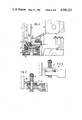
- FIG. 1 is a side view showing a coupling device before a coupling operation
- FIG. 2 is a side view illustrating the coupling device with a coupled drive shaft
- FIG. 3 is a side view showing the effect of the coupling device with an articulated drive shaft
- FIG. 4 is a sectional view showing the coupling parts in greater detail
- FIG. 5 is a sectional view taken through an articulation point
- FIG. 6 is a sectional view through an articulation point having a toothed disc support.
- the coupling device illustrated in the drawings essentially consists of a coupling hub 1 which can be attached to a power take-off shaft, into which a freewheeling unit has been incorporated and with which two bearings 22 are associated.
- a drive shaft 10 to be coupled is provided with an outer joint yoke 23 which ends in a coupling sleeve 2 corresponding to the coupling hub 1.
- a first articulation point 9 pivotally mounting a supporting arm 6 which is held by the force of a spring 8 and which is composed of two telescoping parts loaded outwardly by the force of a pressure spring 7.
- the coupling sleeve 2 corresponding to the coupling hub 1 is held from above through a bearing 4 by a holding device 12 connected to the supporting arm by means of an articulation point 5.
- the supporting arm 6 and the drive shaft 10 For initially coupling an implement to an agricultural tractor, the supporting arm 6 and the drive shaft 10 must be aligned manually so as to be in the coupling position.
- the locking mechanism between the coupling hub 1 and the coupling sleeve 2 is disengaged by operating the swivel lever 11 and the tractor is moved away from the implement.
- the supporting arm 6 and the drive shaft 10 will continue to extend until the maximum extended length of the supporting arm 6 has been achieved.
- the coupling sleeve 2 is pulled away from the coupling hub 1 and remains in this extended position as a result of the tensioned articulation points 5 and 9 of the supporting arm 6.
- the tractor is moved towards the implement until the coupling sleeve 2 is again connected to the coupling hub 1.
- the coupling points of a three point attaching device which is easy to observe from the tractor seat.
- FIG. 2 shows the coupling device with the drive shaft 10 being connected.
- FIG. 3 shows a coupling device in the case of which the drive shaft 10 and the supporting arm 6 are articulated due to the different power take-off shaft heights at the tractor and at the agricultural implement.
- FIG. 4 shows the cooperation between the coupling hub 1 and the coupling sleeve 2.
- the coupling hub 1 is attached to a power take-off shaft 24 and is locked by locking members 13 which are disengageable from their locked position by operation of the swivel lever 11 acting on a disengaging flange 14.
- the hub 1 is also provided with a freewheeling unit 21, with the two coupling hub parts being supported relative to each other by bearings 22.
- the bearing 4 connects the coupling sleeve 2 to the holding device 12 which is connected to the supporting arm 6 by the articulation point 5.
- FIG. 5 is a sectional view showing how the articulation points 5 or 9 may be structured.
- the compressed ends of the supporting arm 6, together with the end piece 15 connected to the pressure spring 7, are rotatably connected relative to another member by a screw 18.
- a friction disc 16 which, in connection with the tension of the spring 17, causes a certain stiffness of the articulation points 5 or 9, with the stiffness being adjustable via the screw 18.
- the supporting arm 6 is capable of handling these bending forces up to a certain extent.
- FIG. 6 shows an alternative construction for the articulation points 5 or 9 wherein, instead of the friction disc 16, provision is made for two corresponding toothed discs 19 and 20 which permit a step-wise adjustment of the articulation points (5 and 9).
- the drive shaft 10 is preferably firmly installed at the implement to be attached and coupled to the tractor take-off shaft at the tractor end.
- the invention operates to provide a coupling device which, for the farmer, facilitates frequent coupling and uncoupling of the drive shaft.
- the objective of the invention is achieved by providing, for example, the power take-off shaft of the tractor with a coupling part having an integrated freewheeling unit and by holding the drive shaft at the implement to be coupled by a supporting arm adjustable in the case of stiff bearing areas.
Landscapes
- Engineering & Computer Science (AREA)
- General Engineering & Computer Science (AREA)
- Mechanical Engineering (AREA)
- Life Sciences & Earth Sciences (AREA)
- Soil Sciences (AREA)
- Environmental Sciences (AREA)
- Agricultural Machines (AREA)
- Beverage Vending Machines With Cups, And Gas Or Electricity Vending Machines (AREA)
- Preliminary Treatment Of Fibers (AREA)
Applications Claiming Priority (2)
| Application Number | Priority Date | Filing Date | Title |
|---|---|---|---|
| DE3302379A DE3302379C2 (de) | 1983-01-25 | 1983-01-25 | Kuppelvorrichtung |
| DE3302379 | 1983-01-25 |
Publications (1)
| Publication Number | Publication Date |
|---|---|
| US4588323A true US4588323A (en) | 1986-05-13 |
Family
ID=6189146
Family Applications (1)
| Application Number | Title | Priority Date | Filing Date |
|---|---|---|---|
| US06/572,576 Expired - Fee Related US4588323A (en) | 1983-01-25 | 1984-01-20 | Coupling device |
Country Status (6)
| Country | Link |
|---|---|
| US (1) | US4588323A (fr) |
| JP (1) | JPS59140804A (fr) |
| DE (1) | DE3302379C2 (fr) |
| FR (1) | FR2539576B1 (fr) |
| GB (1) | GB2133963B (fr) |
| IT (3) | IT8305211A1 (fr) |
Cited By (9)
| Publication number | Priority date | Publication date | Assignee | Title |
|---|---|---|---|---|
| DE4000460A1 (de) * | 1988-11-14 | 1991-07-11 | Durotech Co | Schnelleinrueck- und -trennkupplung |
| US6354383B1 (en) | 2000-04-07 | 2002-03-12 | Harold D. Muilenburg | Attachment device for an implement |
| US20030060098A1 (en) * | 2001-09-18 | 2003-03-27 | Tomohiro Fuse | Coupler mounting structure for vessels |
| US6619686B1 (en) | 2001-08-07 | 2003-09-16 | Jerry Edwards | Folding towbar and lock mechanism |
| US20070177938A1 (en) * | 2006-01-31 | 2007-08-02 | Deere & Company, A Delaware Corporation | Automatic locking ball coupler for power take off |
| US20090103972A1 (en) * | 2007-09-11 | 2009-04-23 | Gkn Walterscheid Gmbh | Device for Coupling A Universal Joint Shaft With A Power Take-Off Shaft Of A Tractor |
| US20140371043A1 (en) * | 2012-03-21 | 2014-12-18 | Futura S.P.A. | Transmission device for embossing rollers |
| US9615502B1 (en) | 2016-06-29 | 2017-04-11 | Alamo Group Inc. | Adjustable agricultural implement driveshaft assembly holder and implement fitted with same |
| US10343518B2 (en) * | 2017-01-25 | 2019-07-09 | Deere & Company | Work implement PTO support assembly |
Families Citing this family (1)
| Publication number | Priority date | Publication date | Assignee | Title |
|---|---|---|---|---|
| JPS6420006A (en) * | 1987-07-15 | 1989-01-24 | Matsuyama Kk | Apparatus for transmitting power of tractor to working machine |
Citations (2)
| Publication number | Priority date | Publication date | Assignee | Title |
|---|---|---|---|---|
| US4157019A (en) * | 1976-09-25 | 1979-06-05 | Jean Walterscheid Gmbh | Releasable coupling device for a power transmission shaft |
| US4169686A (en) * | 1976-12-04 | 1979-10-02 | Jean Walterscheid Gmbh | Quick release coupling for connection between shafts |
Family Cites Families (5)
| Publication number | Priority date | Publication date | Assignee | Title |
|---|---|---|---|---|
| DE1159677B (de) * | 1956-11-30 | 1963-12-19 | Massey Harris Ferguson Inc | Einrichtung zum Anhaengen und Antreiben eines an einen Ackerschlepper anzuhaengendenlandwirtschaftlichen Geraetes |
| DE2414715C3 (de) * | 1974-03-27 | 1979-11-15 | Kloeckner-Humboldt-Deutz Ag, 5000 Koeln | Kupplungsvorrichtung |
| FR2365722A2 (fr) * | 1975-08-23 | 1978-04-21 | Walterscheid Gmbh Jean | Accouplement separable rapide pour reunir deux arbres |
| US4099594A (en) * | 1976-09-08 | 1978-07-11 | Sperry Rand Corporation | Tongue-mounted assembly for supporting an implement driveline |
| DE2743072C3 (de) * | 1977-09-24 | 1980-03-20 | Jean Walterscheid Gmbh, 5204 Lohmar | Entkupplungsvorrichtung |
-
1983
- 1983-01-25 DE DE3302379A patent/DE3302379C2/de not_active Expired
- 1983-10-26 IT IT1983A05211A patent/IT8305211A1/it unknown
- 1983-10-26 IT IT05211/83A patent/IT1195447B/it active
- 1983-10-26 IT IT8307060U patent/IT8307060V0/it unknown
-
1984
- 1984-01-04 GB GB08400113A patent/GB2133963B/en not_active Expired
- 1984-01-17 JP JP59004924A patent/JPS59140804A/ja active Pending
- 1984-01-20 US US06/572,576 patent/US4588323A/en not_active Expired - Fee Related
- 1984-01-25 FR FR8401145A patent/FR2539576B1/fr not_active Expired
Patent Citations (2)
| Publication number | Priority date | Publication date | Assignee | Title |
|---|---|---|---|---|
| US4157019A (en) * | 1976-09-25 | 1979-06-05 | Jean Walterscheid Gmbh | Releasable coupling device for a power transmission shaft |
| US4169686A (en) * | 1976-12-04 | 1979-10-02 | Jean Walterscheid Gmbh | Quick release coupling for connection between shafts |
Cited By (12)
| Publication number | Priority date | Publication date | Assignee | Title |
|---|---|---|---|---|
| DE4000460A1 (de) * | 1988-11-14 | 1991-07-11 | Durotech Co | Schnelleinrueck- und -trennkupplung |
| US6354383B1 (en) | 2000-04-07 | 2002-03-12 | Harold D. Muilenburg | Attachment device for an implement |
| US6619686B1 (en) | 2001-08-07 | 2003-09-16 | Jerry Edwards | Folding towbar and lock mechanism |
| US20030060098A1 (en) * | 2001-09-18 | 2003-03-27 | Tomohiro Fuse | Coupler mounting structure for vessels |
| US6729920B2 (en) * | 2001-09-18 | 2004-05-04 | Honda Giken Kogyo Kabushiki Kaisha | Coupler mounting structure for vessels |
| US20070177938A1 (en) * | 2006-01-31 | 2007-08-02 | Deere & Company, A Delaware Corporation | Automatic locking ball coupler for power take off |
| US7641415B2 (en) * | 2006-01-31 | 2010-01-05 | Deere & Company | Automatic locking ball coupler for power take off |
| US20090103972A1 (en) * | 2007-09-11 | 2009-04-23 | Gkn Walterscheid Gmbh | Device for Coupling A Universal Joint Shaft With A Power Take-Off Shaft Of A Tractor |
| US7997362B2 (en) | 2007-09-11 | 2011-08-16 | Gkn Walterscheid Gmbh | Device for coupling a universal joint shaft with a power take-off shaft of a tractor |
| US20140371043A1 (en) * | 2012-03-21 | 2014-12-18 | Futura S.P.A. | Transmission device for embossing rollers |
| US9615502B1 (en) | 2016-06-29 | 2017-04-11 | Alamo Group Inc. | Adjustable agricultural implement driveshaft assembly holder and implement fitted with same |
| US10343518B2 (en) * | 2017-01-25 | 2019-07-09 | Deere & Company | Work implement PTO support assembly |
Also Published As
| Publication number | Publication date |
|---|---|
| GB2133963A (en) | 1984-08-08 |
| DE3302379A1 (de) | 1984-07-26 |
| DE3302379C2 (de) | 1985-05-02 |
| IT8305211A1 (it) | 1985-04-26 |
| FR2539576A1 (fr) | 1984-07-27 |
| FR2539576B1 (fr) | 1987-02-27 |
| IT8307060V0 (it) | 1983-10-26 |
| GB2133963B (en) | 1985-10-23 |
| GB8400113D0 (en) | 1984-02-08 |
| IT1195447B (it) | 1988-10-19 |
| IT8305211A0 (it) | 1983-10-26 |
| JPS59140804A (ja) | 1984-08-13 |
Similar Documents
| Publication | Publication Date | Title |
|---|---|---|
| US5765851A (en) | Self-aligning towing apparatus | |
| US4588323A (en) | Coupling device | |
| US5303790A (en) | Quick attaching power take off | |
| WO2001040700A1 (fr) | Systeme de bras articule servant a fixer differents dispositifs d'imagerie medicale a des structures de support d'une maniere articulee | |
| US4560300A (en) | Disengageable coupling mechanism for a drive shaft assembly | |
| USRE35835E (en) | Device for attaching an agricultural implement to a tractor | |
| US5339907A (en) | Device for connecting an agricultural implement to a tractor | |
| CA2070786A1 (fr) | Caravane munie d'un dispositif de remorquage et de centrage | |
| US3889980A (en) | Three-point attachment device particularly for a tractor | |
| US4421340A (en) | Coupling means comprising a centering device and a locking mechanism for a motor driven utility unit having a complementary unit | |
| US3284098A (en) | Load-transferring and oscillation damping trailer hitch | |
| DE69101102T3 (de) | Kupplungssystem zwischen Schlepper und einem Halbanbau-Anhänger. | |
| DE102005035561A1 (de) | Gelenkfahrzeug, insbesondere Gelenkbus | |
| US4792006A (en) | Drive shaft coupling | |
| DE102010049167A1 (de) | Dreipunkt-Kuppelvorrichtung | |
| NZ209218A (en) | Winch assembly:shaped link component slidingly inter-fits aperture in winch body | |
| EP0171586B1 (fr) | Frein à friction pour couplages entre véhicule et remorque | |
| US6015016A (en) | Stowable driveline connection aid for power-driven farm implements | |
| US2749995A (en) | Tractor-implement hitch mechanism with power take-off and booster | |
| US5873229A (en) | Coupling arrangement | |
| DE19709431A1 (de) | Einrichtung zum Verstellen von Scheinwerfern bei Fahrzeugen | |
| CH675858A5 (fr) | ||
| DE930063C (de) | Automatische Anhaenger-Maulkupplung | |
| GB2186174A (en) | Telescopic automatic pickup hitch | |
| US3517492A (en) | Implement control assembly |
Legal Events
| Date | Code | Title | Description |
|---|---|---|---|
| AS | Assignment |
Owner name: JEAN WALTERSCHEID GMBH HAUPTSTRASSE 150, 5204 LOHM Free format text: ASSIGNMENT OF ASSIGNORS INTEREST.;ASSIGNORS:VOLLMER, JURGEN;HERCHENBACH, PAUL;REEL/FRAME:004220/0575 Effective date: 19840109 |
|
| FEPP | Fee payment procedure |
Free format text: PAYER NUMBER DE-ASSIGNED (ORIGINAL EVENT CODE: RMPN); ENTITY STATUS OF PATENT OWNER: LARGE ENTITY Free format text: PAYOR NUMBER ASSIGNED (ORIGINAL EVENT CODE: ASPN); ENTITY STATUS OF PATENT OWNER: LARGE ENTITY |
|
| REMI | Maintenance fee reminder mailed | ||
| LAPS | Lapse for failure to pay maintenance fees | ||
| STCH | Information on status: patent discontinuation |
Free format text: PATENT EXPIRED DUE TO NONPAYMENT OF MAINTENANCE FEES UNDER 37 CFR 1.362 |
|
| FP | Lapsed due to failure to pay maintenance fee |
Effective date: 19900513 |