US4475644A - Method and apparatus for feeding lumber - Google Patents
Method and apparatus for feeding lumber Download PDFInfo
- Publication number
- US4475644A US4475644A US06/389,105 US38910582A US4475644A US 4475644 A US4475644 A US 4475644A US 38910582 A US38910582 A US 38910582A US 4475644 A US4475644 A US 4475644A
- Authority
- US
- United States
- Prior art keywords
- boards
- conveyor
- transverse conveyor
- side boards
- lumber
- Prior art date
- Legal status (The legal status is an assumption and is not a legal conclusion. Google has not performed a legal analysis and makes no representation as to the accuracy of the status listed.)
- Expired - Fee Related
Links
- 238000000034 method Methods 0.000 title claims abstract description 24
- 230000001052 transient effect Effects 0.000 claims abstract description 6
- 230000001105 regulatory effect Effects 0.000 claims 1
- 238000010030 laminating Methods 0.000 abstract description 2
- 238000009966 trimming Methods 0.000 abstract 1
- 238000000926 separation method Methods 0.000 description 7
- 229910000831 Steel Inorganic materials 0.000 description 4
- 239000010959 steel Substances 0.000 description 4
- 230000007423 decrease Effects 0.000 description 1
- 230000003247 decreasing effect Effects 0.000 description 1
- 230000000694 effects Effects 0.000 description 1
- 238000010438 heat treatment Methods 0.000 description 1
- 238000004519 manufacturing process Methods 0.000 description 1
- 230000000630 rising effect Effects 0.000 description 1
Images


Classifications
-
- B—PERFORMING OPERATIONS; TRANSPORTING
- B23—MACHINE TOOLS; METAL-WORKING NOT OTHERWISE PROVIDED FOR
- B23Q—DETAILS, COMPONENTS, OR ACCESSORIES FOR MACHINE TOOLS, e.g. ARRANGEMENTS FOR COPYING OR CONTROLLING; MACHINE TOOLS IN GENERAL CHARACTERISED BY THE CONSTRUCTION OF PARTICULAR DETAILS OR COMPONENTS; COMBINATIONS OR ASSOCIATIONS OF METAL-WORKING MACHINES, NOT DIRECTED TO A PARTICULAR RESULT
- B23Q7/00—Arrangements for handling work specially combined with or arranged in, or specially adapted for use in connection with, machine tools, e.g. for conveying, loading, positioning, discharging, sorting
- B23Q7/16—Loading work on to conveyors; Arranging work on conveyors, e.g. varying spacing between individual workpieces
- B23Q7/18—Orienting work on conveyors
-
- B—PERFORMING OPERATIONS; TRANSPORTING
- B27—WORKING OR PRESERVING WOOD OR SIMILAR MATERIAL; NAILING OR STAPLING MACHINES IN GENERAL
- B27B—SAWS FOR WOOD OR SIMILAR MATERIAL; COMPONENTS OR ACCESSORIES THEREFOR
- B27B25/00—Feeding devices for timber in saw mills or sawing machines; Feeding devices for trees
- B27B25/02—Feeding devices for timber in saw mills or sawing machines; Feeding devices for trees with feed and pressure rollers
-
- B—PERFORMING OPERATIONS; TRANSPORTING
- B27—WORKING OR PRESERVING WOOD OR SIMILAR MATERIAL; NAILING OR STAPLING MACHINES IN GENERAL
- B27B—SAWS FOR WOOD OR SIMILAR MATERIAL; COMPONENTS OR ACCESSORIES THEREFOR
- B27B31/00—Arrangements for conveying, loading, turning, adjusting, or discharging the log or timber, specially designed for saw mills or sawing machines
- B27B31/08—Discharging equipment
-
- B—PERFORMING OPERATIONS; TRANSPORTING
- B65—CONVEYING; PACKING; STORING; HANDLING THIN OR FILAMENTARY MATERIAL
- B65G—TRANSPORT OR STORAGE DEVICES, e.g. CONVEYORS FOR LOADING OR TIPPING, SHOP CONVEYOR SYSTEMS OR PNEUMATIC TUBE CONVEYORS
- B65G47/00—Article or material-handling devices associated with conveyors; Methods employing such devices
- B65G47/74—Feeding, transfer, or discharging devices of particular kinds or types
- B65G47/88—Separating or stopping elements, e.g. fingers
- B65G47/8807—Separating or stopping elements, e.g. fingers with one stop
- B65G47/8823—Pivoting stop, swinging in or out of the path of the article
-
- B—PERFORMING OPERATIONS; TRANSPORTING
- B60—VEHICLES IN GENERAL
- B60W—CONJOINT CONTROL OF VEHICLE SUB-UNITS OF DIFFERENT TYPE OR DIFFERENT FUNCTION; CONTROL SYSTEMS SPECIALLY ADAPTED FOR HYBRID VEHICLES; ROAD VEHICLE DRIVE CONTROL SYSTEMS FOR PURPOSES NOT RELATED TO THE CONTROL OF A PARTICULAR SUB-UNIT
- B60W2510/00—Input parameters relating to a particular sub-units
- B60W2510/06—Combustion engines, Gas turbines
- B60W2510/0657—Engine torque
-
- B—PERFORMING OPERATIONS; TRANSPORTING
- B60—VEHICLES IN GENERAL
- B60W—CONJOINT CONTROL OF VEHICLE SUB-UNITS OF DIFFERENT TYPE OR DIFFERENT FUNCTION; CONTROL SYSTEMS SPECIALLY ADAPTED FOR HYBRID VEHICLES; ROAD VEHICLE DRIVE CONTROL SYSTEMS FOR PURPOSES NOT RELATED TO THE CONTROL OF A PARTICULAR SUB-UNIT
- B60W2710/00—Output or target parameters relating to a particular sub-units
- B60W2710/06—Combustion engines, Gas turbines
- B60W2710/0666—Engine torque
-
- B—PERFORMING OPERATIONS; TRANSPORTING
- B65—CONVEYING; PACKING; STORING; HANDLING THIN OR FILAMENTARY MATERIAL
- B65G—TRANSPORT OR STORAGE DEVICES, e.g. CONVEYORS FOR LOADING OR TIPPING, SHOP CONVEYOR SYSTEMS OR PNEUMATIC TUBE CONVEYORS
- B65G2205/00—Stopping elements used in conveyors to stop articles or arrays of articles
- B65G2205/04—Stopping elements used in conveyors to stop articles or arrays of articles where the stop device is not adaptable
Definitions
- the present invention relates to a method for feeding lumber, especially in connection with a four-band saw, in order to separate and feed side boards.
- the invention also relates to an apparatus for working the method.
- the problem is how to separate the pair of side boards, sawed off from both sides of the log, in order to be further processed--for example trimmed.
- the drawback of the above described method is that the side boards leave the sawing station along the transverse conveyor in disarray, wherefore it is necessary to employ manpower and clearing equipment--a separating pocket and a log hoist--in order to separate the boards from each other and to feed them one by one for further processing.
- the separating pocket the boards tend to turn the wrong side up, i.e. with their cant edge down, so that also swivelling equipment is required in the apparatus.
- the log hoist may break boards and thus cause interruptions in the process. As a whole this kind of apparatus is complicated and susceptible to disturbance. It can be regarded as a hindrance to utilizing the full capacity of the four-band saw.
- the Finnish patent application No. 800563 introduces a lumber feeding apparatus where it has been tried to eliminate the aforementioned drawbacks.
- This application relates to an apparatus where, for instance in the sawing position of a four-band saw, the side boards are transported between side supports along both sides of the block, in a trough on top of support rollers, until the sawing operation is completed.
- the support rollers are for a moment drawn out of the trough, so that the side boards fall into the two pockets located on both sides of the block between the side supports.
- both pockets the boards are pressed against the other stationary pocket and simultaneously against the wall of the trough by means of a moving wall operated by a bellow device filled with pressurized air.
- the purpose of the present invention is to eliminate the above mentioned drawbacks and to realize a simple method and apparatus for feeding lumber, which method and apparatus are suited for separating side boards.
- an object of the present invention is to provide a method of heating side boards that a cut from a piece of lumber, in particular a plurality of side boards that are cut from a log or block in a four-band saw, using a device including at least one side guard and preferably a pair of side guards, for holding the boards against the piece of lumber from which they were cut, a first conveyor for transferring the piece of lumber and side boards to the side guard, a transverse conveyor for conveying the side boards transversely of the first conveyor, stop means for holding the boards against movement on the transverse conveyor, and at least one, and preferably a pair of dropping flaps which are movable to direct boards onto the transverse conveyor, comprising opening the side guards to release the side boards from their piece of lumber, positioning the dropping flaps to direct the side board with their cant edges up, onto the transverse conveyor and moving the stop means into a path of the side boards on the transverse conveyor to shift the boards on the transverse conveyor and preferably into piles on the transverse conveyor.
- a further object of the invention is to provide an apparatus for achieving the aforementioned method.
- the greatest advantages of the feeding method of the invention are its simple structure and its reliability.
- An essential feature of the feeding method and apparatus of the invention is that the side boards are dropped in a controlled fashion onto the transverse conveyor on top of each other and kept there in couples or in similar fashion, and that the actual separation of the boards takes place further off from the log or block line.
- the actual separation of the side boards is carried out while shifting the boards from the transverse conveyor onto another conveyor situated on a lower level.
- the separation takes place on a sloping plane by utilizing specially arranged stopping means.
- FIG. 1 is a side elevational view which shows one preferred embodiment of the invention
- FIG. 2 is a top plan view which shows the embodiment of the invention of FIG. 1;
- FIG. 3 illustrates how the boards are dropped onto the transverse conveyor
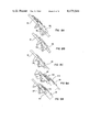
- FIGS. 4 and 5 illustrate how the boards are separated by shifting them from the upper conveyor to the lower conveyor
- FIGS. 6 and 7 illustrate one preferred embodiment of the invention, where boards coming in succession from the conveyor are separated
- FIGS. 8A, 8B, 8C, 9A and 9B illustrate different applications of the invention, which can be employed for separating more than two boards from each other.
- the transportation of the block from the four-band saw, which is not illustrated in the drawing, to the feeding station takes place by a generally known conveyor 10, which is operated for example by means of a gear assembly motor 101 and the chain gearing 102.
- One or several pairs of side guards 11 are arranged at suitable intervals from each other, symmetrically somewhat above the block or log conveyor 10, at both sides thereof.
- the side guards are movably attached to the frame 110 by means of the shafts 111. They are also connected to each other by means of bar 112, to the other end of which bar is also connected the piston of a hydraulic cylinder 113.
- the dropping flaps 12 are formed of shaft-like members attached to a commom axis 121 at suitable intervals, for instance 50 cm between each other.
- the axis 121 is suitably articulated adjacent the conveyor 10.
- the slope of the dropping flaps 12 can be adjusted by means of the hydraulic cylinder 122. They are located at either end of the dropping flap 12 outside the space required by the conveyors 13, 14.
- the cylinder part of the hydraulic cylinder 122 is attached for example to the frame of the conveyors 13, 14 and the piston to the shaft-like member of the dropping flap 12.
- the transverse conveyors 13, 14 are generally known chain or band conveyors, which are mounted on the frame 130 below the first conveyor 10. Both conveyors are operated by means of gear assembly motors 131, 141 and the chain gearing 132, 142.
- the folder wheels of the conveyors 13, 14 are geared to the same axis 133 so that each conveyor can be driven both forwards and backwards.
- transient stops 16, 17, 18 Associated with conveyors 13, 14 are transient stops 16, 17, 18.
- the stops for instance the stop 16, are formed of suitably bended shafts 162 attached to the axis 161.
- the axis is geared below the conveyor 13.
- the shafts 162 are located in the transverse direction of the conveyor 14 for example at one meter intervals.
- the stops 16, 17 and 18 have two positions: the upper position, where they hinder the boards from shifting on the conveyor, and the lower position, where they are turned aside and release the boards to move freely on the conveyor.
- the position of the stops is suitably adjusted by means of the hydraulic cylinders.
- the conveyors 13, 14 are connected to equivalent conveyors 21 located on a lower level, which conveyors are similarily provided with transient stops 22, 23.
- the sloping plane 19 is formed for example of steel bars 135 (FIG. 4) attached at definite intervals to the frame 130, which steel bars are covered by a steel plate 134. Below the steel bars are installed the supports 136, whereto the axis 201 of the stopping member 20 is suitably connected.
- the stopping members 20 are formed of hook-like or chape-like members 202, welded to the axis 201 at suitable intervals, for example at the distance of one meter between each other.
- To the stopping member 20 located near the end of the axis 201 is connected the piston of the hydraulic cylinder 203, which cylinder is attached to the frame.
- the stopping members have preferably one or several intermediate positions for separating the boards. In the lowermost position (B, FIG. 5) the stopping members 20 are completely under the sloping plane 19.
- the feeding apparatus of the invention functions in the following fashion.
- the block 1 together with its side boards is transported from the sawing station to the feeding station.
- the side boards 2, 3 are pressed against the block 1 with the side guards 11, until the conveyor 10 has transported the sawed log to the vicinity of the dropping flaps 12 and the transverse conveyors 13, 14.
- the side guards 11 are opened and the dropping flaps 12, the slope whereof is suitably adjusted, conduct the side boards 2, 3 onto the transverse conveyors 12, 13.
- FIG. 3 also shows how the side guards 11 are opened at the same time as the dropping flaps 12 are lowered to their lowermost position, and the boards 2 and 3 are directed onto the transverse conveyors 13 and 14 with their cant edge upwards.
- FIG. 4 illustrates a phase where the boards 6 and 7 have arrived at the transient stops 18 of the transverse conveyor 14, and the board 8 has stopped at the stopping members 20 located on the sloping plane 19, and the board 9 has continued to move against the stop 22 of the conveyor 21 located on the lower level.
- the stop 22 is turned aside and allows thus the board 9 to proceed against the stop 23.
- the stop 22 is lifted up and the stopping member 20 lets the board 8 to proceed against the stop 22.
- the stopping member 20 is lifted up by utilizing the hydraulic cylinder 203.
- the stop 18 is lowered and the boards 6 and 7 are released from the conveyor 14 to proceed into separation.
- the feeding process now continues in similar fashion.
- the sloping plane 19 of FIG. 4 has been replaced by an adjustable plane 28.
- an echelonment 30 and stopping members 20 there is arranged an echelonment 30 and stopping members 20.
- the echelonment 30, the plane 28 and the stopping means 20 together form an adjustable pocket or equivalent for separating the side boards.
- the slope of the plane and thus the depth of the pocket can be adjusted according to the thickness of the piece of lumber (FIG. 6).
- the lever 29 stepwise towards the direction c the plane 28 is lifted, and respectively when turning the lever in the direction d, the plane is lowered. Consequently the height of the stopping member 20 changes with respect to the plane 28.
- the echelonment 30 can be adjusted by means of a suitable controller such as the lever 31 (FIG. 7), according to the width of the lumber in process, for separating the boards 24, 25 which arrive in succession from the conveyor 14.
- a suitable controller such as the lever 31 (FIG. 7)
- the lever 31 stepwise towards the direction F
- the distance between the echelonment 30 and the stopping member increases, whereas when turning the lever in the direction E the distance decreases and the pocket becomes narrower.
- FIG. 6 shows how the first board 26 has stopped in the pocket and the second board 27 has proceeded over the first one and met the stop 22 of the lower conveyor 21.
- FIGS. 8 and 9 illustrate two more applications for the sloping plane and the stopping members.
- the stopping members are formed of plate-like or similar members 35, which are operated by the hydraulic cylinder 36 and are parallel to the plane 19 and roughly rectangular in cross-section, and which members are adjustably attached to the immediate neighbourhood of the plane 19.
- FIG. 8 illustrates the different working positions (FIGS. 8A, 8B and 8C of the stopping member.
- the stopping members are formed of stationary stops 33, arranged on the sloping plane 19, and of the hoisting apparatus 32 rising from under the plane 19, by means of which the side boards 34 are lifted and fed one by one or in suitable groups into further processing.
Landscapes
- Engineering & Computer Science (AREA)
- Mechanical Engineering (AREA)
- Life Sciences & Earth Sciences (AREA)
- Wood Science & Technology (AREA)
- Forests & Forestry (AREA)
- Attitude Control For Articles On Conveyors (AREA)
- Special Conveying (AREA)
- De-Stacking Of Articles (AREA)
Applications Claiming Priority (2)
| Application Number | Priority Date | Filing Date | Title |
|---|---|---|---|
| FI811893A FI68373C (fi) | 1981-06-17 | 1981-06-17 | Foerfarande och anordning foer dosering av saogvirke |
| FI811893 | 1981-06-17 |
Publications (1)
| Publication Number | Publication Date |
|---|---|
| US4475644A true US4475644A (en) | 1984-10-09 |
Family
ID=8514504
Family Applications (1)
| Application Number | Title | Priority Date | Filing Date |
|---|---|---|---|
| US06/389,105 Expired - Fee Related US4475644A (en) | 1981-06-17 | 1982-06-16 | Method and apparatus for feeding lumber |
Country Status (6)
| Country | Link |
|---|---|
| US (1) | US4475644A (fi) |
| AT (2) | AT377466B (fi) |
| DE (1) | DE3222824A1 (fi) |
| FI (1) | FI68373C (fi) |
| SE (1) | SE468081B (fi) |
| SU (1) | SU1238726A3 (fi) |
Cited By (6)
| Publication number | Priority date | Publication date | Assignee | Title |
|---|---|---|---|---|
| US6378793B1 (en) * | 2000-09-29 | 2002-04-30 | Stephen G. Lantz | Multi-purpose spreader |
| US20070144663A1 (en) * | 2005-12-23 | 2007-06-28 | Huber Engineered Woods L.L.C. | Process for manufacture of oriented strand lumber products |
| US20070151662A1 (en) * | 2005-12-23 | 2007-07-05 | Huber Engineered Woods L.L.C. | Integrated process for simultaneous manufacture of oriented strand lumber and board products |
| US8684652B2 (en) | 2010-10-15 | 2014-04-01 | Sanofi-Aventis U.S. Llc | Apparatus and method for loading and unloading containers |
| US9090411B2 (en) | 2010-10-15 | 2015-07-28 | Sanofi-Aventis U.S. Llc | Apparatus and method for loading and unloading containers |
| CN112281678A (zh) * | 2020-11-20 | 2021-01-29 | 苏州三佳交通工程有限公司 | 一种用于桥梁的木方储存装置 |
Families Citing this family (5)
| Publication number | Priority date | Publication date | Assignee | Title |
|---|---|---|---|---|
| DE3415932A1 (de) * | 1984-04-28 | 1985-11-07 | Gebrüder Linck Maschinenfabrik und Eisengießerei "Gatterlinck", 7602 Oberkirch | Vorrichtung zur spanenden bearbeitung der seiten von holzstaemmen |
| SE9101115L (sv) * | 1991-04-12 | 1992-09-07 | Eriksson Ab A K | Saett och anordning foer att vid en saagutrustning aastadkomma separation mellan flera samtidigt avskilda braedor |
| SE468633B (sv) * | 1991-04-22 | 1993-02-22 | Soederhamns Verkstaeder Ab | Anordning foer avskiljning av braedor fraan ett stamblock |
| DE102008063511B3 (de) * | 2008-12-10 | 2010-07-01 | Esterer Wd Gmbh | Vorrichtung zum Zerlegen von Baumstämmen |
| RU2703442C2 (ru) * | 2015-01-22 | 2019-10-16 | Логкон Хортинорр Аб | Обеспечивающее транспортную обработку дров устройство |
Citations (5)
| Publication number | Priority date | Publication date | Assignee | Title |
|---|---|---|---|---|
| US2468036A (en) * | 1945-10-02 | 1949-04-26 | Crown Zellerbach Corp | Mechanical off-bearing flared rolls |
| US2588484A (en) * | 1950-07-05 | 1952-03-11 | Crown Zellerbach Corp | Mechanical off-bearing means |
| US4240477A (en) * | 1979-05-29 | 1980-12-23 | Saab-Scania Aktiebolag | Movable support assembly for a board infeed system |
| US4286638A (en) * | 1980-02-13 | 1981-09-01 | Bruce Connolly | Apparatus for measuring, cutting and splitting logs |
| US4289180A (en) * | 1978-10-27 | 1981-09-15 | Frank Weinzierl | Bandsaw mill |
Family Cites Families (9)
| Publication number | Priority date | Publication date | Assignee | Title |
|---|---|---|---|---|
| US3209890A (en) * | 1962-10-18 | 1965-10-05 | Thomas R Miles | Feeding apparatus |
| US3486602A (en) * | 1966-05-26 | 1969-12-30 | Stetson Ross Machine Co Inc | Transfer system overdrop with lumber retarder |
| US3565236A (en) * | 1968-10-21 | 1971-02-23 | Us Plywood Champ Papers Inc | Feeder for veneer crowder |
| US3716084A (en) * | 1970-02-13 | 1973-02-13 | Hartzell Industries | Sawmill off bearer |
| SE337104B (fi) * | 1970-03-10 | 1971-07-26 | Kockum Soederhamn Ab | |
| US3812951A (en) * | 1972-05-16 | 1974-05-28 | Weyerhaeuser Co | Log handling apparatus |
| DE2428440A1 (de) * | 1974-06-12 | 1976-01-02 | Boehl Gmbh Maschf | Vorrichtung zur materialaustragung an holz-saegewerksmaschinen |
| FR2441469A2 (fr) * | 1977-03-18 | 1980-06-13 | Vigneau Jacques | Dispositif perfectionne de sciage de pieces de bois comportant au moins une face plane |
| SE415864B (sv) * | 1979-02-27 | 1980-11-10 | Kockums Ind Ab | Fordelningsanordning for sortering av sidobredor styckevis omedelbart efter sagning av stockar |
-
1981
- 1981-02-11 AT AT0063581A patent/AT377466B/de not_active IP Right Cessation
- 1981-06-17 FI FI811893A patent/FI68373C/fi not_active IP Right Cessation
-
1982
- 1982-06-15 SE SE8203701A patent/SE468081B/sv not_active IP Right Cessation
- 1982-06-16 SU SU823463757A patent/SU1238726A3/ru active
- 1982-06-16 US US06/389,105 patent/US4475644A/en not_active Expired - Fee Related
- 1982-06-17 AT AT0235582A patent/AT383983B/de active
- 1982-06-18 DE DE19823222824 patent/DE3222824A1/de not_active Ceased
Patent Citations (5)
| Publication number | Priority date | Publication date | Assignee | Title |
|---|---|---|---|---|
| US2468036A (en) * | 1945-10-02 | 1949-04-26 | Crown Zellerbach Corp | Mechanical off-bearing flared rolls |
| US2588484A (en) * | 1950-07-05 | 1952-03-11 | Crown Zellerbach Corp | Mechanical off-bearing means |
| US4289180A (en) * | 1978-10-27 | 1981-09-15 | Frank Weinzierl | Bandsaw mill |
| US4240477A (en) * | 1979-05-29 | 1980-12-23 | Saab-Scania Aktiebolag | Movable support assembly for a board infeed system |
| US4286638A (en) * | 1980-02-13 | 1981-09-01 | Bruce Connolly | Apparatus for measuring, cutting and splitting logs |
Cited By (6)
| Publication number | Priority date | Publication date | Assignee | Title |
|---|---|---|---|---|
| US6378793B1 (en) * | 2000-09-29 | 2002-04-30 | Stephen G. Lantz | Multi-purpose spreader |
| US20070144663A1 (en) * | 2005-12-23 | 2007-06-28 | Huber Engineered Woods L.L.C. | Process for manufacture of oriented strand lumber products |
| US20070151662A1 (en) * | 2005-12-23 | 2007-07-05 | Huber Engineered Woods L.L.C. | Integrated process for simultaneous manufacture of oriented strand lumber and board products |
| US8684652B2 (en) | 2010-10-15 | 2014-04-01 | Sanofi-Aventis U.S. Llc | Apparatus and method for loading and unloading containers |
| US9090411B2 (en) | 2010-10-15 | 2015-07-28 | Sanofi-Aventis U.S. Llc | Apparatus and method for loading and unloading containers |
| CN112281678A (zh) * | 2020-11-20 | 2021-01-29 | 苏州三佳交通工程有限公司 | 一种用于桥梁的木方储存装置 |
Also Published As
| Publication number | Publication date |
|---|---|
| FI68373B (fi) | 1985-05-31 |
| DE3222824A1 (de) | 1983-02-10 |
| SE8203701L (sv) | 1982-12-18 |
| SU1238726A3 (ru) | 1986-06-15 |
| ATA235582A (de) | 1987-02-15 |
| AT383983B (de) | 1987-09-10 |
| ATA63581A (de) | 1984-08-15 |
| FI811893L (fi) | 1982-12-18 |
| FI68373C (fi) | 1985-09-10 |
| AT377466B (de) | 1985-03-25 |
| SE468081B (sv) | 1992-11-02 |
Similar Documents
| Publication | Publication Date | Title |
|---|---|---|
| US5205705A (en) | Apparatus and process for feeding panels to a panel cutting saw | |
| US2228887A (en) | Stacker and unloader | |
| US4475644A (en) | Method and apparatus for feeding lumber | |
| CH671566A5 (fi) | ||
| CN110722359A (zh) | 变压器硅钢片剪叠机 | |
| DE3705169A1 (de) | Verfahren und vorrichtung zum verpacken von druckerzeugnissen | |
| EP0106019B1 (en) | Machine for stacking automatically packs of panels of different sizes on respective lifting platforms | |
| GB2060571A (en) | Device for stacking flat articles such as box blanks | |
| US3917078A (en) | Elongate-material transport system | |
| DE3414996C1 (de) | Vorrichtung zum Abschieben von auf einer Trageinrichtung abgelegten Stapeln oder Paketen | |
| US6155775A (en) | Destacking feeder | |
| US4413941A (en) | Machine tool support table and feeding device | |
| DE2702724C2 (de) | Einrichtung zum Sortieren und Ablegen von Zuschnitten bei Plattenaufteilanlagen | |
| US4776741A (en) | Stacking device for stacking elongated goods | |
| GB2134891A (en) | Apparatus for manipulating stacks of paper sheets or the like | |
| US3687260A (en) | Edging picker | |
| US3557952A (en) | Apparatus for handling sawn timber | |
| US3143344A (en) | Sheet stacker | |
| US4299149A (en) | Apparatus for removing and stacking of sheet metal strips cut by a plate shear | |
| US3595415A (en) | Elevator with a pivoted support deck | |
| US6086322A (en) | Automated circuit board tester | |
| US6386824B1 (en) | Apparatus for processing layers such as stack layers of paper | |
| US3224307A (en) | Method and apparatus for handling sheet materials | |
| US4157176A (en) | Apparatus for precisely stacking textile pieces of sheetlike form | |
| US3467253A (en) | Method and an apparatus for the sorting by length of sawn and planed timber and for the piling of the same |
Legal Events
| Date | Code | Title | Description |
|---|---|---|---|
| AS | Assignment |
Owner name: PLAN-SELL OY, MANNERHEIMINTIE 25 A 29, OO250 HELSI Free format text: ASSIGNMENT OF ASSIGNORS INTEREST.;ASSIGNOR:RAIPPO, JORMA;REEL/FRAME:004056/0452 Effective date: 19820603 |
|
| AS | Assignment |
Owner name: A. AHLSTROM OSAKEYHTIO 48601 KARHULA, FINLAND A CO Free format text: ASSIGNMENT OF ASSIGNORS INTEREST.;ASSIGNOR:PLAN-SELL OY;REEL/FRAME:004116/0884 Effective date: 19830411 |
|
| CC | Certificate of correction | ||
| FPAY | Fee payment |
Year of fee payment: 4 |
|
| FPAY | Fee payment |
Year of fee payment: 8 |
|
| REMI | Maintenance fee reminder mailed | ||
| LAPS | Lapse for failure to pay maintenance fees | ||
| FP | Lapsed due to failure to pay maintenance fee |
Effective date: 19961009 |
|
| STCH | Information on status: patent discontinuation |
Free format text: PATENT EXPIRED DUE TO NONPAYMENT OF MAINTENANCE FEES UNDER 37 CFR 1.362 |