US4452513A - Zoom lens capable of close range photography and method of focusing the same to a short distance - Google Patents
Zoom lens capable of close range photography and method of focusing the same to a short distance Download PDFInfo
- Publication number
- US4452513A US4452513A US06/387,677 US38767782A US4452513A US 4452513 A US4452513 A US 4452513A US 38767782 A US38767782 A US 38767782A US 4452513 A US4452513 A US 4452513A
- Authority
- US
- United States
- Prior art keywords
- sub
- group
- focusing
- lens
- represent
- Prior art date
- Legal status (The legal status is an assumption and is not a legal conclusion. Google has not performed a legal analysis and makes no representation as to the accuracy of the status listed.)
- Expired - Lifetime
Links
Images
Classifications
-
- G—PHYSICS
- G02—OPTICS
- G02B—OPTICAL ELEMENTS, SYSTEMS OR APPARATUS
- G02B15/00—Optical objectives with means for varying the magnification
- G02B15/14—Optical objectives with means for varying the magnification by axial movement of one or more lenses or groups of lenses relative to the image plane for continuously varying the equivalent focal length of the objective
- G02B15/144—Optical objectives with means for varying the magnification by axial movement of one or more lenses or groups of lenses relative to the image plane for continuously varying the equivalent focal length of the objective having four groups only
- G02B15/1441—Optical objectives with means for varying the magnification by axial movement of one or more lenses or groups of lenses relative to the image plane for continuously varying the equivalent focal length of the objective having four groups only the first group being positive
- G02B15/144113—Optical objectives with means for varying the magnification by axial movement of one or more lenses or groups of lenses relative to the image plane for continuously varying the equivalent focal length of the objective having four groups only the first group being positive arranged +-++
Definitions
- This invention relates to a zoom lens which can be continuously focused to objects from infinity to a very short distance.
- photographic lenses are designed with infinity object distance as the standard and therefore, when they are focused to a short distance object, their imaging performance is usually aggravated.
- various focusing methods for short distance photography have been proposed to enhance their multi-function, but the deterioration of their imaging performance at short distances is substantial and therefore, even in a lens having a good imaging performance for infinity object distance, aggravation of various aberrations is substantial during photographing of short distance objects and thus, such a lens has not been practical unless it is stopped down considerably.
- a zoom lens is basically much more bulky in construction than a fixed focus lens having the same focal length as the focal length on the wide side.
- the aperture of the first group must be made larger and this makes it necessary to give sufficient consideration to the compactness of the lens shape. If the aperture of the lens is made small, the quantity of marginal light is liable to become deficient particularly at short distances and, if the full length of the lens and the focal length of the first group are made short, correction of various aberrations will become difficult and therefore, it has been very difficult to maintain good imaging performance for short distances while keeping the shape of the entire lens system compact.
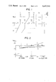
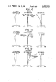
- FIG. 1 shows an example of the locus of movement of a second lens group and a third lens group for magnification change and an example of the locus of movement of a first lens group and the second group for focusing.
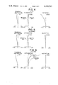
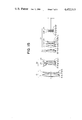
- FIG. 2 illustrates the relation between the object distance and the height of the principal ray incident on the first group in a first embodiment.
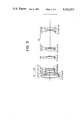
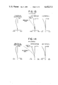
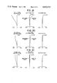
- FIG. 3 shows the lens arrangement of the first embodiment in the shortest focal length condition.
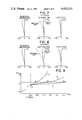
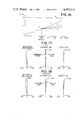
- FIG. 4 shows the aberrations in the first embodiment during infinity photography.
- FIG. 10 shows the aberrations in the second embodiment in the infinity photography condition.
- FIG. 16 like FIG. 2, shows a comparison between the incidence positions of the principal ray in a third embodiment.
- FIG. 17 shows the aberrations in the third embodiment at infinity.
- the zoom lens according to the present invention is a zoom lens which, as shown in FIG. 1, has, in sucession from the object side, a first lens group G 1 as a convergent focusing group, a second lens group G 2 as a divergent magnification changing group, a third lens group G 3 as a convergent correcting group, and a convergent fourth lens group G 4 as a relay system and in which the second group G 2 and the third group G 3 are movable relative to each other along the optical axis to thereby effect magnification change while keeping the image plane at a predetermined position and wherein focusing to objects at distances between infinity and a predetermined short distance is accomplished by movement of only the first group G 1 toward the object side and focusing to an object at a distance shorter than said predetermined short distance is accomplished by moving the first group G 1 and the second group G 2 at the same time along the optical axis while maintaining the third group at a predetermined position relative to the image plane.
- the second group G 2 and the third group G 3 are first moved to or near the shortest focal length condition (wide end).
- the first group G 1 is singly moved toward the object side by a predetermined amount to thereby accomplish focusing, and then in addition to the further movement of the first group G 1 toward the object side, the second group G 2 is also moved toward the object side to thereby accomplish focusing to an object at a distance shorter than the predetermined short distance.
- the focusing by solo movement of the first group G 1 will hereinafter be referred to as the first focusing
- the focusing by the first group G 1 and the second group G 2 will hereinafter be referred to as the second focusing.
- FIG. 1 shows an example of the locus of movement of the second group G 2 and the third group G 3 for magnification change and an example of the locus of movement of the first group G 1 and the second group G 2 for focusing.
- the area I shows the condition of the first focusing
- the area II shows the condition of the second focusing.
- the tendencies of astigmatism and curvature of image field are reversed by the first focusing, and up to a position whereat they return to the order of the values of aberration before the first group is axially moved or a position whereat they assume values slightly positive therefrom, the first group G 1 alone is moved and when focusing is to be effected to a distance shorter than this, the second focusing in which the second group G 2 is also moved is adopted, whereby focusing up to a very short distance can be accomplished without aggravating astigmatism and curvature of image field. It has been found that, according to this second focusing, spherical aberration does not vary so much and the aggravation of the various aberrations can be minimized.
- the construction of the present invention is advantageous in preventing the deficiency of the quantity of marginal light which is liable to occur during short distance photography.
- the first focusing in which focusing is accomplished by movement of the convergent first group toward the object side, the position at which a light ray of wide angle of view is incident on the first group gradually becomes more distant from the optical axis and at least deviated from the effective diameter of the first group, so that deficiency of quantity of light is caused in the marginal portion of the image. Therefore, in the case of the first focusing which has heretofore been usually practised, it is necessary to increase the lens aperture to prevent the deficiency of the quantity of marginal light.
- the refractive power of the first group is suitably increased and the second focusing in which the divergent second group in addition to the first group is moved toward the object side is effected, whereby the position at which a light ray of wide angle of view at the short distance is incident on the first group can be kept at a relatively short distance from the optical axis with the result that decrease in quantity of marginal light is prevented while the lens aperture of the first group is kept as small as possible, thereby enabling very close range photography having a good imaging performance.
- the vertical axis represents the incidence height of the principal ray of a maximum angle of view incident on the first group, the incidence height being expressed as a value standardized by the incidence height h ⁇ in the condition focused to an infinity object.
- the horizontal axis represents the shortness of the object distance, which is expressed as the value of the ratio of the shortest focal length fw of the entire system to the object distance R.
- straight line d shows the incidence position of the marginal ray from the infinity object on the axis and represents the magnitude of the minimum aperture of the first group necessary to maintain predetermined brightness of the lens system.
- ⁇ D 1 the amount of variation in the principal point spacing between the first group and the second group
- ⁇ D 2 the amount of variation in the principal point spacing between the second group and the third group
- Condition (1) prescribes the optimum range of amount of movement of the first and second groups during very close range photography.
- Condition (2) is the ratio of the refractive power of the first group to the refractive power of the entire system in the shortest focal length condition and prescribes the refractive power to be borne by the first group.
- the refractive power of the first group will become great and therefore it wil become difficult to correct the various aberrations in the first group.
- fluctuations of spherical aberration and astigmatism will become excessive on the long focal length side as compared with the infinity photography condition and this is unsuitable.
- a predetermined zoom ratio must be obtained and therefore, the narrowed principal point spacing between the respective groups must be compensated for by intensifying the refractive power of each group of the zoom portion and thus, correction of aberrations will again be difficult.
- condition (3) prescribes the amount corresponding to the incidence height at which the principal ray of a maximum angle of view at infinity crosses the first lens surface, and also prescribes an appropriate range of position of the entrance pupil.
- the second group G 2 comprise, in succession from the object side, a cemented lens component L 21 consisting of three negative, positive and negative lenses L 2a , L 2b and L 2c cemented together and having a composite negative refractive power, and a negative lens component L 22 and that the following conditions be satisfied: ##EQU2## where r 6 represents the radius of curvature of that surface in the second group which is most adjacent to the object side, f 2 represents the composite focal length of the second group, f 21 and f 22 represent the focal lengths of the cemented negative lens component L 21 and the negative lens component L 22 , respectively, in the second group, f 2a , f 2b , and f 2c represent the focal lengths of the negative, positive and negative lenses L 2a , L 2b and L 2c constituting the cemented negative lens component L 21 , and ⁇ 2a , ⁇ 2b and ⁇ 2c represent the Abbe numbers of these lenses.
- the various aberrations for the standard wavelength have been corrected to a certain degree, but the fluctuation of chromatic aberration by zooming could not be corrected perfectly, whereas the present invention has succeeded in well balancing the various aberrations for the standard wavelength and the fluctuation of chromatic aberration by zooming by forming the negative lens component in the second group which is adjacent to the objective side by three lenses cemented together.
- the difference in refractive index for the standard wavelength has not been made so great but the difference in dispersion has been made great on the opposite sides of the first cemented surface r 7 formed by the negative lens L 2a and the positive lens L 2b while, on the other hand, the difference in refractive index for the standard wavelength has been positively made great on the opposite sides of the second cemented surface r 8 formed by the positive lens L 2b and the negative lens L 2c .
- Condition (4) is for minimizing the bending of the best image plane when the second group is also moved toward the object side with the first group in the second focusing system according to the present invention and thereby always maintaining a stable image plane. If the lower limit of this condition is exceeded, the foremost lens surface r 6 in the second group will become convex toward the object side and therefore, aggravation of various aberrations will be substantial during short distance photography at the telephoto end and the bending of the image plane at the wide angle end will be substantial. Conversely, if the curvature of the foremost lens surface r 6 becomes sharper beyond the upper limit of this condition, distortion at the wide angle will become so noticeable that it will be difficult to correct the fluctuation of distortion resulting from zooming.
- Conditions (5) and (6) are for balancing the correction of chromatic aberration while well correcting the various aberrations for the standard wavelength, particularly the fluctuation of coma resulting from zooming, by the two cemented surfaces in the second group.
- Condition (5) is concerned with the first cemented surface r 7 convex toward the object side which is formed by the negative lens L 2a and the positive lens L 2b
- condition (6) is concerned with the second cemented surface r 8 convex toward the image side which is formed by the positive lens L 2b and the negative lens L 2c .
- the first cemented surface r 7 is convex toward the object side, it is advantageous for the correction of chromatic aberration but is not very effective for the correction of coma, and since the second cemented surface r 8 is convex toward the image side, it is liable to create chromatic aberration but is effective for the correction of coma. If the upper limits of conditions (5) and (6) are exceeded, on-axis chromatic aberration will become excessively positive particularly on the long focal length side and chromatic difference of magnification will become excessively negative on the short focal length side and these will both be under-corrected, with the second group having a negative refractive power.
- on-axis chromatic aberration and chromatic difference of magnification can be corrected only in the same sense and therefore, it is necessary that appropriate balance of the on-axis chromatic aberration and chromatic difference of magnification in the second group be maintained by conditions (5) and (6).
- Table 1 below shows the lens data thereof
- Table 2 below shows the focal length of the wide end of each lens group, the arrangement of each lens group relative to the principal point spacing during close range photography and very close range photography, and the basic lens construction parameters.
- the manner in which the incidence height of the principal ray is deteriorated during close range photography and during very close range photography is shown in the microfocus system, and the comparison between respective systems is as shown in FIG. 2.
- FIG. 3 shows the lens arrangement in the shortest focal length condition
- FIG. 4 shows the aberrations during infinity photography
- a second embodiment in a zoom lens of focal length f 71.8-204 mm and F-number 4.0, and its zoom ratio is about 3.
- Table 3 below shows the numerical data of each lens and Table 4 below, like Table 2 of the first embodiment, shows each value.
- the arrangement of the lens system is substantially identical to that of FIG. 3 and therefore is not shown.
- FIG. 9, like FIG. 2 shows the relation between the object distance and the height of the principal ray incident on the first group in the second embodiment. As can be seen from FIG.
- FIG. 10 shows the aberrations in the infinity photography condition.
- FIGS. 13 and 14 show the aberrations when the first and second groups have been moved toward the object side in the conditions of ##EQU3## respectively.
- Table 5 below shows the numerical data of each lens
- Table 6 below shows the parameters which prescribe the basic construction of the lens.
- FIG. 16 like FIGS. 2 and 9, shows a comparison between the incidence positions of the principal ray, and
- FIG. 17 shows the aberrations at infinity.
- FIG. 19 shows the aberrations when focusing has been accomplished by moving only the first group toward the object side, and FIGS.
- the decrease in quantity of marginal light is very small and this is very advantageous.
- a zoom lens which not only has an excellent imaging performance in ordinary photography but also can be continuously focused to objects from infinity to a short distance and in which the aperture of the foremost lens is small to make the entire lens system into a compact shape.
Landscapes
- Physics & Mathematics (AREA)
- General Physics & Mathematics (AREA)
- Optics & Photonics (AREA)
- Lenses (AREA)
Applications Claiming Priority (2)
| Application Number | Priority Date | Filing Date | Title |
|---|---|---|---|
| JP56093728A JPS57208522A (en) | 1981-06-19 | 1981-06-19 | Zoom lens capable of close-up photographing |
| JP56-93728 | 1981-06-19 |
Publications (1)
| Publication Number | Publication Date |
|---|---|
| US4452513A true US4452513A (en) | 1984-06-05 |
Family
ID=14090467
Family Applications (1)
| Application Number | Title | Priority Date | Filing Date |
|---|---|---|---|
| US06/387,677 Expired - Lifetime US4452513A (en) | 1981-06-19 | 1982-06-11 | Zoom lens capable of close range photography and method of focusing the same to a short distance |
Country Status (3)
| Country | Link |
|---|---|
| US (1) | US4452513A (de) |
| JP (1) | JPS57208522A (de) |
| DE (1) | DE3222899C2 (de) |
Cited By (4)
| Publication number | Priority date | Publication date | Assignee | Title |
|---|---|---|---|---|
| GB2281409A (en) * | 1991-12-25 | 1995-03-01 | Asahi Optical Co Ltd | Three group zoom lens system |
| US5418648A (en) * | 1992-05-26 | 1995-05-23 | Fuji Photo Optical Co., Ltd. | Varifocal lens system |
| US5543969A (en) * | 1991-12-25 | 1996-08-06 | Asahi Kogaku Kogyo Kabushiki Kaisha | Zoom lens system |
| US20140078598A1 (en) * | 2012-09-14 | 2014-03-20 | Canon Kabushiki Kaisha | Zoom lens and projector using the same |
Families Citing this family (3)
| Publication number | Priority date | Publication date | Assignee | Title |
|---|---|---|---|---|
| JPS59188611A (ja) * | 1983-04-09 | 1984-10-26 | Olympus Optical Co Ltd | ズ−ムレンズ |
| FR2626681B1 (fr) * | 1988-02-02 | 1992-11-20 | Angenieux P Ets | Objectif a focale variable permettant une mise au point tres rapprochee |
| JPH02150092A (ja) * | 1988-12-01 | 1990-06-08 | Canon Inc | プリント配線板相互の接続構造 |
Citations (2)
| Publication number | Priority date | Publication date | Assignee | Title |
|---|---|---|---|---|
| US3884555A (en) * | 1972-09-22 | 1975-05-20 | Canon Kk | Optical system capable of extreme close up photography |
| US4240699A (en) * | 1975-11-05 | 1980-12-23 | Canon Kabushiki Kaisha | Zoom lens having extended focusing range |
Family Cites Families (5)
| Publication number | Priority date | Publication date | Assignee | Title |
|---|---|---|---|---|
| JPS5132635A (en) * | 1974-09-14 | 1976-03-19 | Tokina Optical | Shikinkyorisatsueikanonazuumurenzukei |
| BR7607801A (pt) * | 1975-12-08 | 1977-10-11 | Xerox Corp | Aparelho manejador de documento e aparelho armazenador de documento |
| JPS5270848A (en) * | 1975-12-10 | 1977-06-13 | Tokina Optical | Zoom lens that can take very near objects |
| JPS5562422A (en) * | 1978-09-11 | 1980-05-10 | Optigon Res & Dev Corp | Zoom lens |
| US4230397A (en) * | 1978-09-21 | 1980-10-28 | Bell & Howell Company | Large aperture extended range zoom lens |
-
1981
- 1981-06-19 JP JP56093728A patent/JPS57208522A/ja active Granted
-
1982
- 1982-06-11 US US06/387,677 patent/US4452513A/en not_active Expired - Lifetime
- 1982-06-18 DE DE3222899A patent/DE3222899C2/de not_active Expired - Lifetime
Patent Citations (2)
| Publication number | Priority date | Publication date | Assignee | Title |
|---|---|---|---|---|
| US3884555A (en) * | 1972-09-22 | 1975-05-20 | Canon Kk | Optical system capable of extreme close up photography |
| US4240699A (en) * | 1975-11-05 | 1980-12-23 | Canon Kabushiki Kaisha | Zoom lens having extended focusing range |
Cited By (6)
| Publication number | Priority date | Publication date | Assignee | Title |
|---|---|---|---|---|
| GB2281409A (en) * | 1991-12-25 | 1995-03-01 | Asahi Optical Co Ltd | Three group zoom lens system |
| GB2281409B (en) * | 1991-12-25 | 1995-10-11 | Asahi Optical Co Ltd | Three group zoom lens system |
| US5543969A (en) * | 1991-12-25 | 1996-08-06 | Asahi Kogaku Kogyo Kabushiki Kaisha | Zoom lens system |
| US5418648A (en) * | 1992-05-26 | 1995-05-23 | Fuji Photo Optical Co., Ltd. | Varifocal lens system |
| US20140078598A1 (en) * | 2012-09-14 | 2014-03-20 | Canon Kabushiki Kaisha | Zoom lens and projector using the same |
| US8891174B2 (en) * | 2012-09-14 | 2014-11-18 | Canon Kabushiki Kaisha | Zoom lens and projector using the same |
Also Published As
| Publication number | Publication date |
|---|---|
| JPS57208522A (en) | 1982-12-21 |
| DE3222899A1 (de) | 1983-01-05 |
| DE3222899C2 (de) | 1994-09-29 |
| JPS6151772B2 (de) | 1986-11-10 |
Similar Documents
| Publication | Publication Date | Title |
|---|---|---|
| JP2538526B2 (ja) | ズ−ムレンズ | |
| US4787718A (en) | Zoom lens system | |
| US4830476A (en) | Compact zoom lens system | |
| US6246519B1 (en) | Zoom lens system with vibration reduction function | |
| US5585969A (en) | Zoom lens | |
| US5076677A (en) | Zoom lens | |
| JP2558138B2 (ja) | 変倍レンズ | |
| JPH05264902A (ja) | ズームレンズ | |
| US4506958A (en) | Compact zoom lens system | |
| US4871243A (en) | Photographic lens of improved near distance performance | |
| US5805351A (en) | High speed wide angle zoom lens system | |
| JPH07120677A (ja) | コンパクトな3群ズームレンズ | |
| US4266860A (en) | Wide angle zoom lens system having shortened closeup focal length | |
| JP3018723B2 (ja) | ズームレンズ | |
| JPH07107577B2 (ja) | ズ−ムレンズ | |
| US4025167A (en) | Telephoto-type zoom lens system | |
| JPH0634885A (ja) | ズームレンズ | |
| JPH0668575B2 (ja) | 小型のズ−ムレンズ | |
| JP3369689B2 (ja) | ズームレンズ | |
| JPH07120678A (ja) | 3群ズームレンズのフォーカシング方式 | |
| JP3369598B2 (ja) | 変倍レンズ | |
| US4452513A (en) | Zoom lens capable of close range photography and method of focusing the same to a short distance | |
| JPH085920A (ja) | ズームレンズ | |
| US4189213A (en) | Zoom lens system | |
| JP2546293B2 (ja) | 小型のズームレンズ |
Legal Events
| Date | Code | Title | Description |
|---|---|---|---|
| AS | Assignment |
Owner name: NIPPON KOGAKU K.K., 2-3, MARUNOUCHI 3-CHOME, CHIYO Free format text: ASSIGNMENT OF ASSIGNORS INTEREST.;ASSIGNOR:HAMANISHI, YOSHINARI;REEL/FRAME:004008/0356 Effective date: 19820609 |
|
| STCF | Information on status: patent grant |
Free format text: PATENTED CASE |
|
| FEPP | Fee payment procedure |
Free format text: PAYOR NUMBER ASSIGNED (ORIGINAL EVENT CODE: ASPN); ENTITY STATUS OF PATENT OWNER: LARGE ENTITY |
|
| FPAY | Fee payment |
Year of fee payment: 4 |
|
| AS | Assignment |
Owner name: NIKON CORPORATION, 2-3, MARUNOUCHI 3-CHOME, CHIYOD Free format text: CHANGE OF NAME;ASSIGNOR:NIPPON KOGAKU, K.K.;REEL/FRAME:004935/0584 |
|
| FPAY | Fee payment |
Year of fee payment: 8 |
|
| FPAY | Fee payment |
Year of fee payment: 12 |