US4258587A - Power transmission unit for an automotive vehicle - Google Patents
Power transmission unit for an automotive vehicle Download PDFInfo
- Publication number
- US4258587A US4258587A US05/877,767 US87776778A US4258587A US 4258587 A US4258587 A US 4258587A US 87776778 A US87776778 A US 87776778A US 4258587 A US4258587 A US 4258587A
- Authority
- US
- United States
- Prior art keywords
- shaft
- gear
- drive
- idler
- main shaft
- Prior art date
- Legal status (The legal status is an assumption and is not a legal conclusion. Google has not performed a legal analysis and makes no representation as to the accuracy of the status listed.)
- Expired - Lifetime
Links
Images


Classifications
-
- B—PERFORMING OPERATIONS; TRANSPORTING
- B60—VEHICLES IN GENERAL
- B60K—ARRANGEMENT OR MOUNTING OF PROPULSION UNITS OR OF TRANSMISSIONS IN VEHICLES; ARRANGEMENT OR MOUNTING OF PLURAL DIVERSE PRIME-MOVERS IN VEHICLES; AUXILIARY DRIVES FOR VEHICLES; INSTRUMENTATION OR DASHBOARDS FOR VEHICLES; ARRANGEMENTS IN CONNECTION WITH COOLING, AIR INTAKE, GAS EXHAUST OR FUEL SUPPLY OF PROPULSION UNITS IN VEHICLES
- B60K17/00—Arrangement or mounting of transmissions in vehicles
- B60K17/04—Arrangement or mounting of transmissions in vehicles characterised by arrangement, location, or kind of gearing
-
- B—PERFORMING OPERATIONS; TRANSPORTING
- B60—VEHICLES IN GENERAL
- B60K—ARRANGEMENT OR MOUNTING OF PROPULSION UNITS OR OF TRANSMISSIONS IN VEHICLES; ARRANGEMENT OR MOUNTING OF PLURAL DIVERSE PRIME-MOVERS IN VEHICLES; AUXILIARY DRIVES FOR VEHICLES; INSTRUMENTATION OR DASHBOARDS FOR VEHICLES; ARRANGEMENTS IN CONNECTION WITH COOLING, AIR INTAKE, GAS EXHAUST OR FUEL SUPPLY OF PROPULSION UNITS IN VEHICLES
- B60K5/00—Arrangement or mounting of internal-combustion or jet-propulsion units
- B60K5/02—Arrangement or mounting of internal-combustion or jet-propulsion units with the engine main axis, e.g. crankshaft axis, substantially in or parallel to the longitudinal centre line of the vehicle
Definitions
- the present invention relates to generally a power transmission unit for an automotive vehicle and more particularly to a compact arrangement of a clutch, a change speed gearing and a final drive suitable for use with a front-engine front-drive type and a rear-engine rear-drive type automotive vehicles.
- British Patent No. 1,084,452 discloses a power transmission unit for a motor vehicle including a change-speed gearing having a layshaft and an associated mainshaft which is supported in a pair of axially spaced journal bearings, a disengageable coupling or clutch having a power input member for connection to the crankshaft of the vehicle engine and a power output member having a driving gear, the axes of the layshaft and mainshaft being parallel to and spaced from the axis of rotation of the disengageable coupling, the driving gear being arranged to drive a power input gear for the change-speed gearing through an intermediate idler gear, which power input gear is arranged between the said mainshaft journal bearings.
- British Patent No. 1,084,453 also discloses a propulsion plant for a motor road vehicle in which a change-speed gearing and a differential gearing, for driving a pair of independently-suspended road wheels, are supported from a reciprocating type internal combustion engine such that the differential gearing is below the engine crankshaft, a disengageable coupling is adapted to be connected to the engine to drive a power transmission shaft coaxial with the engine crankshaft and drivingly connected to a driving gear, the change-speed gearing has a layshaft with a layshaft gears for selectively driving respective complementary gears on a mainshaft which is connected to drive the power input member of the differential gearing, the mainshaft is supported by two axially spaced bearings, and a power input gear for the change-speed gearing is journalled on the mainshaft between said bearings to mesh with one of said layshaft gears and is arranged to be driven from the transmission shaft by said driving gear which is arranged in a housing that is fast with the housing of the change-
- the change-speed gearing is disposed immediately below the clutch which has a relatively large diameter so that the automotive vehicle is inevitably high. Since the differential gearing is disposed closer to the front of the vehicle, the wheel base becomes longer so that the weight distributed on the front wheels is reduced. As a result, the slippage of the front wheels tends to occur very often when the vehicle is ascending a grade, and the maneuverability and stability are adversely affected especially in case of turning.
- the minimum turning radius is increased, and the front overhang becomes shorter so that the fender and the front portion of the wheel arch may not sufficiently cover the front wheels, the bumber may not have sufficient strength and the design of the vehicle is not satisfactory.
- one of the objects of the present invention is to provide a power transmission unit for an automotive vehicle which may reduce the overall height of the vehicle.
- Another object of the present invention is to provide a power transmission unit for an automotive vehicle which may be less extended rearward into the compartment so that the reduction in usable inner dimensions of the compartment may be avoided and the arrangement of various pedals within the compartment will not be adversely affected.
- a further object of the present invention is to provide a power transmission unit for an automotive vehicle which may define a suitable wheel base and a sufficiently long front overhang so that the weight distributed on the wheels may be increased and consequently the grade ability or the hill-climbing ability as well as the maneuverability and stability may be improved, the minimum turning radius may be reduced and the design of the fender and its associated parts may be much facilitated.
- a power transmission unit for an automotive vehicle comprising a disengageable coupling means having a power output shaft extending coaxially with and disengageably coupled to a crankshaft of an engine, a change speed gearing including a main shaft and a counter shaft both disposed downwardly from and in parallel with the power output shaft, and change speed gear trains carried on the main and counter shafts and arranged rearwardly downwardly from the coupling means, means for operatively coupling the power output shaft to the change speed gearing, a drive pinion shaft disposed immediately below the coupling means and having a front end and a rear end which is coupled to the main shaft, and a final drive including a drive pinion carried on the front end of the drive pinion shaft and a ring gear constantly in mesh with the drive pinion.
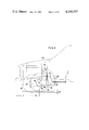
- FIG. 1 is a sectional view in elevation of a first embodiment of a power transmission unit of the present invention
- FIGS. 2 and 3 show the comparison in mounting on an automotive vehicle between the transmission unit in accordance with the present invention and the prior art transmission units;
- FIG. 4 is a sectional view in elevation of a second embodiment of the present invention.
- FIG. 5 is a schematic view illustrating a third embodiment of the present invention.
- a crankshaft of an engine 10 is drivingly connected to a flywheel 12A formed integral with a starter ring gear 12B and a clutch 12 which is a disengageable coupling means and which has a clutch output shaft 14.
- the axis of the clutch 12 is in parallel with the longitudinal axis of an automotive vehicle.
- An idler shaft 15 which is disposed below the clutch output shaft 14 in parallel therewith carries an idler gear 18 which is in constant mesh with a drive gear 16 carried by the clutch output shaft 14.
- a main shaft 22 is disposed immediately below the idler shaft 15 and in parallel with the clutch output shaft 14 and the main shaft 22 carries an input gear 20 which is in constant mesh with the idler gear 18 and which is not keyed or splined to the main shaft 22 so that it idlely rotates on the main shaft 22.
- the main shaft 22 is extended rearward away from the engine 10 and the clutch 12 and carries a third speed gear 24A, a second speed gear 24B and a first speed gear 24C.
- a fifth-speed gear (or an overdrive gear) 24D is formed integral with the main shaft 22 at the front end thereof for rotation in unison therewith.
- Synchronizing mechanisms 26A and 26B which constitute intertia type (Borg-Warner type) synchromesh mechanisms are interposed between the input gear 20 and the third speed gear 24A and between the second speed gear 24B and the first speed gear 24C. These synchronizing mechanisms 26A and 26B are keyed or splined to the main shaft 22 for slidable movement along the main shaft 22.
- the synchronizing mechanism 26A engages with either of a gear spline integral with the input gear 20 or a gear spline 25A formed integral with the third-speed gear 24A while the synchronizing mechanism 26B engages with either of a gear spline 25B formed integral with the second speed gear 24B or a gear spline 25C formed integral with the first speed gear 24C.
- Each of the synchronizing mechanisms 26A and 26B is caused to engage with the corresponding gear spline after the speeds of the synchronizing mechanism and the gear spline have been synchronized by a synchronizing ring and shifting keys (not shown).
- a countershaft 28 is disposed in parallel with the main shaft 22 and at the same height as the main shaft 22, but for the sake of simplicity in illustration the countershaft 28 is shown as being disposed below the main shaft 22 in FIG. 1.
- the countershaft 28 carries a countershaft drive gear 30 which is formed integral with the countershaft 28 and which is in constant mesh with the input gear 20 which rotates idlely on the main shaft 22.
- the countershaft 28 further carries a countershaft third-speed gear 32A in constant mesh with the main shaft third speed gear 24A, a countershaft second speed gear 32B in constant mesh with the main shaft second speed gear 24B and a countershaft first speed gear 32C in constant mesh with the main shaft first speed gear 24C.
- the countershaft 28 further carries a countershaft fifth speed gear 32D which is not keyed or splined to the countershaft 28 and is in constant mesh with the main shaft fifth speed gear 24D and is formed integral with a gear spline 25D.
- a synchronizing mechanism 26D is splined to the countershaft 28 for slidable movement therealong for engagement with the gear spline 25D of the fifth speed gear 32D, whereby the rotation of the countershaft 28 is transmitted to the main shaft 22.
- the front end of the main shaft 22 is connected through a spline joint 35 to the rear end of a drive pinion shaft 34 which is extended below the clutch 12 and which carries a drive pinion 36 at the front end.
- the drive pinion 36 is made in constant mesh with a ring gear 38 which in turn is drivingly coupled to a differential gear assembly 40 which in turn is coupled to front axles (not shown) so as to drive front wheels (not shown).
- the drive pinion 36 and the ring gear 38 constitute a final drive.
- a casing for enclosing the power transmission unit with the construction described above consists of a transaxle case 46, a transmission case 48 and an intermediate plate 50 sandwiched between the cases 46 and 48.
- the case 46 defines a first chamber 46A for enclosing the clutch 12, the flywheel 12A and the starter ring gear 12B, a second chamber 46B enclosing the fifth speed gearing and a third chamber 46C for enclosing the final drive (the drive pinion 36 and the ring gear 38) and the differential gear assembly 40.
- the first chamber 46A is securely fixed to the cylinder block of the engine 10 with bolts (not shown), whereby the case 46 is firmly attached to the engine 10.
- the intermediate plate 50 is attached to the rear end face of the first chamber 46A.
- the second chamber 46B is defined below the first chamber 46A and is partitioned therefrom by a partition wall 52.
- the rear end opening of the second chamber 46B is closed by the intermediate plate 50.
- the third chamber 46C is defined frontward of the second chamber 46B and is separated therefrom by a partition wall 54.
- the third chamber 46C is extended in the form of a cantilever below the engine 10 and is spaced apart therefrom by a suitable small distance.
- the front opening end of the third chamber 46C is closed with a cover 56.
- the transmission case 48 is securely mounted with a plurality of bolts on the transmission axle case 46 with the intermediate plate 50 interposed therebetween.
- the free end of the clutch output shaft 14 is supported by the intermediate plate 50, and the idler shaft 15, the main shaft 22 and the countershaft 28 are supported between the intermediate plate 50 and the transmission case 48.
- the main shaft cluster of gears and the countershaft cluster of gears are enclosed within the space defined by the intermediate plate 50 and the transmission case 48.
- An extension housing 58 is joined to the rear end of the transmission case 48 and supports a gearshift lever (not shown).
- the second synchronizing mechanism 26B on the main shaft 22 is caused to slide rearward for engagement with the gear spline 25C so that the main shaft first speed gear 24C is locked to the main shaft 22, whereby the power is transmitted to the main shaft 22 and consequently to the final drive (the drive pinion 36 in mesh with the ring gear 38).
- the gearshift to the second, third or fifth speed position may be accomplished.
- the first synchronizing mechanism 26A is moved to the left and engaged with the gear spline 23A of the input gear 20, whereby the input gear 20 is locked to the main shaft 22.
- an idle gear 15A carried by the idler shaft 15 is brought into mesh with a reverse gear 15B formed integral with the synchronizing mechanism 26A through an idle gear (not shown).
- the idler shaft 18, the main shaft 22 and the countershaft 28 are attached with the gears and bearings at both ends. Each shaft is held vertically such that the lower bearing may be fitted into a corresponding bearing hole in the intermediate plate 50 which is maintained horizontally.
- the upper bearings are fitted into the corresponding bearing holes in the transmission case 48.
- the subassembly consisting of the transmission case 48, the intermediate plate 50 and the idle, main and counter shafts 18, 22 and 28 is attached with the bolts to the rear end face of the transmission axle case 46 which is mounted on the cylinder block of the engine 10.
- the intermediate plate 50 may greatly simplify and facilitate the assembly. Furthermore in case of a transmission trouble, only the transmission may be readily removed. Furthermore when the automotive vehicle is ascending or descending a grade, the transmission unit is tilted, but the intermediate plate 50 effectively serves to prevent the flow of the lubrication oil from the transmission case 48 into the second chamber 46B or vice versa. Moreover, the intermediate plate 50 may serve to increase the rigidity of the transmission unit and to suppress the noise and vibration transmitted to the compartment.
- FIG. 3 there is shown the power transmission unit mounted on an automotive vehicle generally indicated by the reference numeral 60.
- the transmission unit in accordance with the present invention is very advantageous. That is, according to the present invention, only the main shaft 22 or the drive pinion shaft 34 is disposed immediately below the clutch 12 which has relatively a large diameter, while in the prior art transmission unit the transmission gears are disposed below the clutch. As a result, the height of vehicle in accordance with the present invention may be reduced by ⁇ H as compared with the vehicle equipped with the prior art power transmission unit.
- the transmission gears are disposed backwardly of the input gear 20 so that the final drive and the differential gear assembly 40 may be disposed immediately below the engine 10 adjacent to the rear end thereof.
- the wheel base may be reduced ⁇ L, and the front wheels 62 may bear more distributed weight of the vehicle 60 so that the slippage of the front wheel when the car is ascending a grade may be eliminated, the maneuverability and stability especially in case of turning may be remarkably improved and the minimum turning radius may be reduced.
- front overhang A may be considerably increased so that a front fender may be so designed and constructed as to sufficiently cover the front wheels 62 and the fender as well as its associated parts may be improved in mechanical strength.
- FIG. 3 illustrates the advantages of the transmission unit in accordance with the present invention over the prior art power transmission unit of the type described in the above Japanese Utility Model Publication and indicated by the two-dot chain lines. Since the final drive as well as the differential gear assembly 40 of the prior art transmission unit are disposed immediately below the clutch 12 which has a relatively large diameter, the height of the transmission unit is high, and the front wheels 62 must be attached backwardly of the engine 10 so that a pedal 64 must be displaced backwardly by ⁇ R, as compared with the unit of the invention. Consequently the usable interior dimensions of the compartment are decreased. Furthermore the countershaft 28 is further extended backward so that the usable interior dimensions of the compartment are further reduced.
- the clutch output shaft 14 has been described as being drivingly coupled through the idle gear 18 to the main shaft drive gear 20, but it is to be understood that the clutch output shaft 14 may be drivingly coupled to the input gear 20 through any suitable transmission mechanisms such as a combination of a chain and sprocket wheels. Furthermore, instead of the four speed transmission the transmissions having any number of speeds may be used.
- the second embodiment of the present invention shown in FIG. 4 is substantially similar in construction to the first embodiment described above except that a power transfer means generally designated by the reference numeral 70 is disposed within the extension housing 58 for four-wheel drive.
- the power transfer means 70 consists of a sleeve 72 splined to the main shaft 22 and a connecting rod 74 which in turn is connected drivingly to a propeller shaft connected to rear wheels. When the sleeve 72 is brought into engagement with splines 76 of the connecting rod 74, the power is transmitted not only to the front wheels but also to the rear wheels.
- the engine 10 and the power transmission unit are mounted on the automotive vehicle 60 nearly at the midpoint between the front and rear ends for driving the rear wheels 80.
- This type of the engine mounting is called the midship type engine.
- the height of the automotive vehicle 60 may be reduced, and the space indicated by 82 adjacent to the rear end may be advantageously utilized.
Applications Claiming Priority (2)
| Application Number | Priority Date | Filing Date | Title |
|---|---|---|---|
| JP1478877A JPS53100534A (en) | 1977-02-14 | 1977-02-14 | Automotive power transmitting system |
| JP52-14788 | 1977-02-14 |
Publications (1)
| Publication Number | Publication Date |
|---|---|
| US4258587A true US4258587A (en) | 1981-03-31 |
Family
ID=11870785
Family Applications (1)
| Application Number | Title | Priority Date | Filing Date |
|---|---|---|---|
| US05/877,767 Expired - Lifetime US4258587A (en) | 1977-02-14 | 1978-02-14 | Power transmission unit for an automotive vehicle |
Country Status (7)
| Country | Link |
|---|---|
| US (1) | US4258587A (de) |
| JP (1) | JPS53100534A (de) |
| AU (1) | AU500328B2 (de) |
| CA (1) | CA1077306A (de) |
| DE (1) | DE2805900C2 (de) |
| FR (1) | FR2380156A1 (de) |
| GB (1) | GB1594795A (de) |
Cited By (12)
| Publication number | Priority date | Publication date | Assignee | Title |
|---|---|---|---|---|
| US4335629A (en) * | 1979-04-11 | 1982-06-22 | Fiat Auto S.P.A. | Drive transmission unit incorporating expansible-pulley stepless speed changer |
| US4399717A (en) * | 1980-10-15 | 1983-08-23 | Toyota Jidosha Kogyo Kabushiki Kaisha | Change-speed transmission for wheeled vehicles |
| US4602526A (en) * | 1983-01-18 | 1986-07-29 | Honda Giken Kogyo Kabushiki Kaisha | Transmission/subtransmission mechanism |
| US4976668A (en) * | 1987-12-11 | 1990-12-11 | Honda Giken Kogyo Kabushiki Kaisha | Final reduction gear unit for an automobile |
| US5035682A (en) * | 1987-05-27 | 1991-07-30 | Honda Giken Kogyo Kabushiki Kaisha | Automotive transmission apparatus |
| US5039305A (en) * | 1989-12-18 | 1991-08-13 | Ford Motor Company | Multiple ratio compact transaxle assembly for automotive vehicles |
| US5062822A (en) * | 1987-12-11 | 1991-11-05 | Honda Giken Kogyo Kabushiki Kaisha | Drive system with intermediate shaft for automobiles |
| US5257962A (en) * | 1992-12-18 | 1993-11-02 | Chrysler Corporation | Output assembly for a north-south transaxle |
| EP1393956A1 (de) * | 2002-08-23 | 2004-03-03 | Audi Ag | Antriebsaggregat |
| US6832529B2 (en) * | 2000-01-28 | 2004-12-21 | Fuji Jukogyo Kabushiki Kaisha | Automobile transmission |
| EP1745972A1 (de) * | 2004-01-29 | 2007-01-24 | Yanmar Co. Ltd. | Zugmaschine |
| US20080223644A1 (en) * | 2005-07-14 | 2008-09-18 | Bayerische Motoren Werke Aktiengesellschaft | Vehicle in particular a motorcycle and engine/gearbox unit for a vehicle |
Families Citing this family (8)
| Publication number | Priority date | Publication date | Assignee | Title |
|---|---|---|---|---|
| US4151761A (en) * | 1977-10-03 | 1979-05-01 | Toyota Jidosha Kogyo Kabushiki Kaisha | Air breather for power transmission unit |
| JPS5938134A (ja) * | 1982-07-24 | 1984-03-01 | Honda Motor Co Ltd | 4輪駆動装置 |
| JPS60213526A (ja) * | 1984-04-06 | 1985-10-25 | Iseki & Co Ltd | トラクタの走行変速装置 |
| FR2630054A1 (fr) * | 1988-04-13 | 1989-10-20 | Voisin Marc | Procede de transformation d'un vehicule et transmission pour vehicule |
| JPH03258618A (ja) * | 1990-03-09 | 1991-11-18 | Mazda Motor Corp | 車両のパワートレイン構造 |
| GB9216310D0 (en) * | 1992-07-31 | 1992-09-16 | Mclaren Cars Nv | A transmission assembly for a vehicle |
| US5632354A (en) * | 1993-09-16 | 1997-05-27 | Fuji Jukogyo Kabushiki Kaisha | Motor vehicle with a continuously variable transmission |
| FR2735727B1 (fr) * | 1995-06-22 | 1997-08-14 | Peugeot | Groupe moto-propulseur pour vehicule a moteur dispose longitudinalement |
Citations (3)
| Publication number | Priority date | Publication date | Assignee | Title |
|---|---|---|---|---|
| US3318168A (en) * | 1963-09-25 | 1967-05-09 | Renault | Transmission mechanisms for vehicles having a power unit with built-in transmission and final drive |
| US3799000A (en) * | 1971-03-10 | 1974-03-26 | Peugeot | Transmission with gearbox output shaft and differential input shaft in different vertical planes |
| US4056988A (en) * | 1975-08-08 | 1977-11-08 | Toyota Jidosha Kogyo Kabushiki Kaisha | Driving system for use in motor vehicle |
Family Cites Families (14)
| Publication number | Priority date | Publication date | Assignee | Title |
|---|---|---|---|---|
| BE406472A (de) * | ||||
| BE473754A (de) * | ||||
| GB1011956A (en) * | 1963-05-01 | 1965-12-01 | Ford Motor Co | Motor vehicle drive arrangement |
| GB1008116A (en) * | 1963-08-09 | 1965-10-27 | Ford Motor Co | Motor vehicle transmission-drive line units |
| JPS4528729Y1 (de) * | 1966-05-09 | 1970-11-05 | ||
| GB1114756A (en) * | 1966-11-11 | 1968-05-22 | Vauxhall Motors Ltd | Power transmission systems for motor vehicles |
| FR1552935A (de) * | 1967-10-09 | 1969-01-10 | ||
| GB1165859A (en) * | 1968-06-25 | 1969-10-01 | Standard Triumph Motor Company | Improvements in or relating to a Transmission Unit for a Motor Vehicle |
| FR2028634A5 (de) * | 1969-01-08 | 1970-10-09 | Simca Automobiles Sa | |
| CA905651A (en) * | 1969-06-06 | 1972-07-25 | I. Aronoff Edward | Treating of tubular fabrics |
| FR2052219A5 (de) * | 1969-07-30 | 1971-04-09 | Simca Automobiles Sa | |
| FR2052222A5 (de) * | 1969-07-30 | 1971-04-09 | Simca Automobiles Sa | |
| FR2052221A5 (de) * | 1969-07-30 | 1971-04-09 | Simca Automobiles Sa | |
| DE2256150C3 (de) * | 1972-11-16 | 1979-03-29 | Volkswagenwerk Ag, 3180 Wolfsburg | Gehäuseanordnung mit zwei Gehäuseräumen |
-
1977
- 1977-02-14 JP JP1478877A patent/JPS53100534A/ja active Pending
-
1978
- 1978-02-13 DE DE2805900A patent/DE2805900C2/de not_active Expired
- 1978-02-13 GB GB5697/78A patent/GB1594795A/en not_active Expired
- 1978-02-14 AU AU33293/78A patent/AU500328B2/en not_active Expired
- 1978-02-14 CA CA296,926A patent/CA1077306A/en not_active Expired
- 1978-02-14 US US05/877,767 patent/US4258587A/en not_active Expired - Lifetime
- 1978-02-24 FR FR7805380A patent/FR2380156A1/fr active Granted
Patent Citations (3)
| Publication number | Priority date | Publication date | Assignee | Title |
|---|---|---|---|---|
| US3318168A (en) * | 1963-09-25 | 1967-05-09 | Renault | Transmission mechanisms for vehicles having a power unit with built-in transmission and final drive |
| US3799000A (en) * | 1971-03-10 | 1974-03-26 | Peugeot | Transmission with gearbox output shaft and differential input shaft in different vertical planes |
| US4056988A (en) * | 1975-08-08 | 1977-11-08 | Toyota Jidosha Kogyo Kabushiki Kaisha | Driving system for use in motor vehicle |
Cited By (16)
| Publication number | Priority date | Publication date | Assignee | Title |
|---|---|---|---|---|
| US4335629A (en) * | 1979-04-11 | 1982-06-22 | Fiat Auto S.P.A. | Drive transmission unit incorporating expansible-pulley stepless speed changer |
| US4399717A (en) * | 1980-10-15 | 1983-08-23 | Toyota Jidosha Kogyo Kabushiki Kaisha | Change-speed transmission for wheeled vehicles |
| US4602526A (en) * | 1983-01-18 | 1986-07-29 | Honda Giken Kogyo Kabushiki Kaisha | Transmission/subtransmission mechanism |
| US5035682A (en) * | 1987-05-27 | 1991-07-30 | Honda Giken Kogyo Kabushiki Kaisha | Automotive transmission apparatus |
| US4976668A (en) * | 1987-12-11 | 1990-12-11 | Honda Giken Kogyo Kabushiki Kaisha | Final reduction gear unit for an automobile |
| US5062822A (en) * | 1987-12-11 | 1991-11-05 | Honda Giken Kogyo Kabushiki Kaisha | Drive system with intermediate shaft for automobiles |
| US5039305A (en) * | 1989-12-18 | 1991-08-13 | Ford Motor Company | Multiple ratio compact transaxle assembly for automotive vehicles |
| US5257962A (en) * | 1992-12-18 | 1993-11-02 | Chrysler Corporation | Output assembly for a north-south transaxle |
| US6832529B2 (en) * | 2000-01-28 | 2004-12-21 | Fuji Jukogyo Kabushiki Kaisha | Automobile transmission |
| EP1393956A1 (de) * | 2002-08-23 | 2004-03-03 | Audi Ag | Antriebsaggregat |
| EP1745972A1 (de) * | 2004-01-29 | 2007-01-24 | Yanmar Co. Ltd. | Zugmaschine |
| EP1745972A4 (de) * | 2004-01-29 | 2008-05-28 | Yanmar Co Ltd | Zugmaschine |
| US20080173495A1 (en) * | 2004-01-29 | 2008-07-24 | Yanmar Co., Ltd. | Tractor |
| US8517139B2 (en) | 2004-01-29 | 2013-08-27 | Yanmar Co., Ltd. | Tractor |
| US20080223644A1 (en) * | 2005-07-14 | 2008-09-18 | Bayerische Motoren Werke Aktiengesellschaft | Vehicle in particular a motorcycle and engine/gearbox unit for a vehicle |
| US9260153B2 (en) * | 2005-07-14 | 2016-02-16 | Bayerische Motoren Werke Aktiengesellschaft | Vehicle in particular a motorcycle and engine/gearbox unit for a vehicle |
Also Published As
| Publication number | Publication date |
|---|---|
| CA1077306A (en) | 1980-05-13 |
| GB1594795A (en) | 1981-08-05 |
| AU500328B2 (en) | 1979-05-17 |
| DE2805900A1 (de) | 1978-08-17 |
| FR2380156B1 (de) | 1982-04-23 |
| JPS53100534A (en) | 1978-09-02 |
| DE2805900C2 (de) | 1983-09-15 |
| FR2380156A1 (fr) | 1978-09-08 |
Similar Documents
| Publication | Publication Date | Title |
|---|---|---|
| US4258587A (en) | Power transmission unit for an automotive vehicle | |
| US4193322A (en) | Casing for power transmission unit for automotive vehicle | |
| US4244242A (en) | Lubrication system for differential gear unit | |
| US4033200A (en) | Five speed overdrive transmission | |
| US4643045A (en) | Power transfer device for four wheel drive | |
| US4261219A (en) | Lubrication device for differential gear unit | |
| US4422520A (en) | Transmission apparatus for four-wheel drive motor vehicle | |
| US10138983B2 (en) | Transmission | |
| US4711136A (en) | Power transfer device for four-wheel drive | |
| JP4104091B2 (ja) | 4輪駆動車用手動変速機 | |
| US4399717A (en) | Change-speed transmission for wheeled vehicles | |
| US4669332A (en) | Power transfer device for four wheel drive | |
| KR0164253B1 (ko) | 변속기어유니트 | |
| US6832529B2 (en) | Automobile transmission | |
| US4867001A (en) | Output shaft assembly in power transfer device | |
| CA2211068C (en) | Compact manual transaxle | |
| EP0929761B1 (de) | Kompakte achseinheit mit getriebe | |
| JP2533554Y2 (ja) | 4輪駆動装置 | |
| US4915191A (en) | Transfer device for a four-wheel drive vehicle | |
| GB2345041A (en) | Motor vehicle transmission assembly | |
| US4805713A (en) | Power transmitting system for a four-wheel drive vehicle | |
| JP2802626B2 (ja) | 動力伝達装置のケース構造 | |
| RU2043214C1 (ru) | Трансмиссия полноприводного транспортного средства | |
| US4901590A (en) | Manual transmission for motor vehicle | |
| JP2533555Y2 (ja) | 4輪駆動装置 |
Legal Events
| Date | Code | Title | Description |
|---|---|---|---|
| STCF | Information on status: patent grant |
Free format text: PATENTED CASE |