US4252184A - Control of oil distribution in heated embossing rolls - Google Patents
Control of oil distribution in heated embossing rolls Download PDFInfo
- Publication number
- US4252184A US4252184A US06/128,408 US12840880A US4252184A US 4252184 A US4252184 A US 4252184A US 12840880 A US12840880 A US 12840880A US 4252184 A US4252184 A US 4252184A
- Authority
- US
- United States
- Prior art keywords
- apertures
- roll member
- fluid
- inner shell
- annular chamber
- Prior art date
- Legal status (The legal status is an assumption and is not a legal conclusion. Google has not performed a legal analysis and makes no representation as to the accuracy of the status listed.)
- Expired - Lifetime
Links
Images

Classifications
-
- B—PERFORMING OPERATIONS; TRANSPORTING
- B21—MECHANICAL METAL-WORKING WITHOUT ESSENTIALLY REMOVING MATERIAL; PUNCHING METAL
- B21G—MAKING NEEDLES, PINS OR NAILS OF METAL
- B21G1/00—Making needles used for performing operations
-
- B—PERFORMING OPERATIONS; TRANSPORTING
- B31—MAKING ARTICLES OF PAPER, CARDBOARD OR MATERIAL WORKED IN A MANNER ANALOGOUS TO PAPER; WORKING PAPER, CARDBOARD OR MATERIAL WORKED IN A MANNER ANALOGOUS TO PAPER
- B31F—MECHANICAL WORKING OR DEFORMATION OF PAPER, CARDBOARD OR MATERIAL WORKED IN A MANNER ANALOGOUS TO PAPER
- B31F1/00—Mechanical deformation without removing material, e.g. in combination with laminating
- B31F1/07—Embossing, i.e. producing impressions formed by locally deep-drawing, e.g. using rolls provided with complementary profiles
-
- B—PERFORMING OPERATIONS; TRANSPORTING
- B21—MECHANICAL METAL-WORKING WITHOUT ESSENTIALLY REMOVING MATERIAL; PUNCHING METAL
- B21F—WORKING OR PROCESSING OF METAL WIRE
- B21F5/00—Upsetting wire or pressing operations affecting the wire cross-section
-
- D—TEXTILES; PAPER
- D06—TREATMENT OF TEXTILES OR THE LIKE; LAUNDERING; FLEXIBLE MATERIALS NOT OTHERWISE PROVIDED FOR
- D06C—FINISHING, DRESSING, TENTERING OR STRETCHING TEXTILE FABRICS
- D06C15/00—Calendering, pressing, ironing, glossing or glazing textile fabrics
- D06C15/08—Rollers therefor
-
- D—TEXTILES; PAPER
- D21—PAPER-MAKING; PRODUCTION OF CELLULOSE
- D21G—CALENDERS; ACCESSORIES FOR PAPER-MAKING MACHINES
- D21G1/00—Calenders; Smoothing apparatus
- D21G1/02—Rolls; Their bearings
- D21G1/0253—Heating or cooling the rolls; Regulating the temperature
- D21G1/0266—Heating or cooling the rolls; Regulating the temperature using a heat-transfer fluid
-
- F—MECHANICAL ENGINEERING; LIGHTING; HEATING; WEAPONS; BLASTING
- F16—ENGINEERING ELEMENTS AND UNITS; GENERAL MEASURES FOR PRODUCING AND MAINTAINING EFFECTIVE FUNCTIONING OF MACHINES OR INSTALLATIONS; THERMAL INSULATION IN GENERAL
- F16C—SHAFTS; FLEXIBLE SHAFTS; ELEMENTS OR CRANKSHAFT MECHANISMS; ROTARY BODIES OTHER THAN GEARING ELEMENTS; BEARINGS
- F16C13/00—Rolls, drums, discs, or the like; Bearings or mountings therefor
-
- F—MECHANICAL ENGINEERING; LIGHTING; HEATING; WEAPONS; BLASTING
- F26—DRYING
- F26B—DRYING SOLID MATERIALS OR OBJECTS BY REMOVING LIQUID THEREFROM
- F26B13/00—Machines and apparatus for drying fabrics, fibres, yarns, or other materials in long lengths, with progressive movement
- F26B13/10—Arrangements for feeding, heating or supporting materials; Controlling movement, tension or position of materials
- F26B13/14—Rollers, drums, cylinders; Arrangement of drives, supports, bearings, cleaning
- F26B13/18—Rollers, drums, cylinders; Arrangement of drives, supports, bearings, cleaning heated or cooled, e.g. from inside, the material being dried on the outside surface by conduction
- F26B13/183—Arrangements for heating, cooling, condensate removal
-
- F—MECHANICAL ENGINEERING; LIGHTING; HEATING; WEAPONS; BLASTING
- F28—HEAT EXCHANGE IN GENERAL
- F28D—HEAT-EXCHANGE APPARATUS, NOT PROVIDED FOR IN ANOTHER SUBCLASS, IN WHICH THE HEAT-EXCHANGE MEDIA DO NOT COME INTO DIRECT CONTACT
- F28D11/00—Heat-exchange apparatus employing moving conduits
- F28D11/02—Heat-exchange apparatus employing moving conduits the movement being rotary, e.g. performed by a drum or roller
-
- B—PERFORMING OPERATIONS; TRANSPORTING
- B31—MAKING ARTICLES OF PAPER, CARDBOARD OR MATERIAL WORKED IN A MANNER ANALOGOUS TO PAPER; WORKING PAPER, CARDBOARD OR MATERIAL WORKED IN A MANNER ANALOGOUS TO PAPER
- B31F—MECHANICAL WORKING OR DEFORMATION OF PAPER, CARDBOARD OR MATERIAL WORKED IN A MANNER ANALOGOUS TO PAPER
- B31F2201/00—Mechanical deformation of paper or cardboard without removing material
- B31F2201/07—Embossing
- B31F2201/0707—Embossing by tools working continuously
- B31F2201/0715—The tools being rollers
- B31F2201/0723—Characteristics of the rollers
- B31F2201/073—Rollers having a multilayered structure
-
- B—PERFORMING OPERATIONS; TRANSPORTING
- B31—MAKING ARTICLES OF PAPER, CARDBOARD OR MATERIAL WORKED IN A MANNER ANALOGOUS TO PAPER; WORKING PAPER, CARDBOARD OR MATERIAL WORKED IN A MANNER ANALOGOUS TO PAPER
- B31F—MECHANICAL WORKING OR DEFORMATION OF PAPER, CARDBOARD OR MATERIAL WORKED IN A MANNER ANALOGOUS TO PAPER
- B31F2201/00—Mechanical deformation of paper or cardboard without removing material
- B31F2201/07—Embossing
- B31F2201/0756—Characteristics of the incoming material, e.g. creped, embossed, corrugated
-
- B—PERFORMING OPERATIONS; TRANSPORTING
- B31—MAKING ARTICLES OF PAPER, CARDBOARD OR MATERIAL WORKED IN A MANNER ANALOGOUS TO PAPER; WORKING PAPER, CARDBOARD OR MATERIAL WORKED IN A MANNER ANALOGOUS TO PAPER
- B31F—MECHANICAL WORKING OR DEFORMATION OF PAPER, CARDBOARD OR MATERIAL WORKED IN A MANNER ANALOGOUS TO PAPER
- B31F2201/00—Mechanical deformation of paper or cardboard without removing material
- B31F2201/07—Embossing
- B31F2201/0784—Auxiliary operations
-
- F—MECHANICAL ENGINEERING; LIGHTING; HEATING; WEAPONS; BLASTING
- F16—ENGINEERING ELEMENTS AND UNITS; GENERAL MEASURES FOR PRODUCING AND MAINTAINING EFFECTIVE FUNCTIONING OF MACHINES OR INSTALLATIONS; THERMAL INSULATION IN GENERAL
- F16C—SHAFTS; FLEXIBLE SHAFTS; ELEMENTS OR CRANKSHAFT MECHANISMS; ROTARY BODIES OTHER THAN GEARING ELEMENTS; BEARINGS
- F16C2340/00—Apparatus for treating textiles
-
- Y—GENERAL TAGGING OF NEW TECHNOLOGICAL DEVELOPMENTS; GENERAL TAGGING OF CROSS-SECTIONAL TECHNOLOGIES SPANNING OVER SEVERAL SECTIONS OF THE IPC; TECHNICAL SUBJECTS COVERED BY FORMER USPC CROSS-REFERENCE ART COLLECTIONS [XRACs] AND DIGESTS
- Y10—TECHNICAL SUBJECTS COVERED BY FORMER USPC
- Y10S—TECHNICAL SUBJECTS COVERED BY FORMER USPC CROSS-REFERENCE ART COLLECTIONS [XRACs] AND DIGESTS
- Y10S165/00—Heat exchange
- Y10S165/135—Movable heat exchanger
- Y10S165/139—Fully rotatable
- Y10S165/156—Hollow cylindrical member, e.g. drum
- Y10S165/159—Hollow cylindrical member, e.g. drum with particular flow path or defined fluid chamber, e.g. annulus, spiral
- Y10S165/16—Concentric shells define annular flow space
-
- Y—GENERAL TAGGING OF NEW TECHNOLOGICAL DEVELOPMENTS; GENERAL TAGGING OF CROSS-SECTIONAL TECHNOLOGIES SPANNING OVER SEVERAL SECTIONS OF THE IPC; TECHNICAL SUBJECTS COVERED BY FORMER USPC CROSS-REFERENCE ART COLLECTIONS [XRACs] AND DIGESTS
- Y10—TECHNICAL SUBJECTS COVERED BY FORMER USPC
- Y10S—TECHNICAL SUBJECTS COVERED BY FORMER USPC CROSS-REFERENCE ART COLLECTIONS [XRACs] AND DIGESTS
- Y10S165/00—Heat exchange
- Y10S165/918—Heated and cooled food cabinets and/or trays
- Y10S165/919—Wheeled
Definitions
- the present invention relates to machine rolls for making low basis weight webs, and more specifically to a roll heated with hot oil for use in the manufacture of cellulose webs or polymeric webs or films.
- One of the problem areas in providing a hot-oil heated roll is that with all currently available systems of which applicant is aware, localized hot or cold spots develop on the surface of the roll due to undesirable flow patterns and variable heat transfer from the hot oil, which results in nonuniform bonding patterns within the cellulose or polymeric web.
- One desirable method of distributing heat to the surface of the roll is by the use of an annular space between an outer and an inner roll, with the hot oil being distributed throughout this annular space between the rolls.
- the ultimate purpose of using a heated fluid, such as oil, is to approach a uniform temperature over a predetermined active width of the surface of the roll where embossing or calendering is to take place.
- Nearly uniform temperature is important not only for proper thermal conditions in embossing or calendering, but also to maintain a controlled roll profile and resulting pressure distribution across the roll width in the nip between the rolls.
- Local hot spots in a roll causes local expansion and result in areas of excessive nip pressure.
- a heated roll as envisioned herein typically has a somewhat greater width than the width of the web to be produced so that end conditions in the roll have minimal effect on the active length of the roll nip.
- variation in the level of turbulence has been found to produce differences in heat transfer from the heating medium to the roll. Therefore, the result is nonuniform temperature in many prior art devices where the heating medium is introduced at one end of the roll so that it may move axially to the opposite end.
- Other prior art suggestions include introducing the oil at regularly spaced intervals over the entire width of the roll causing local areas of high turbulence. In any case, the heated oil is introduced perpendicular to the inner surface of the roll to be heated. This results in a "hot spot" in the area where the oil impinges on the inner surface of the roll with "cold spots” therebetween.
- U.S. Pat. No. 4,050,510, Theysohn illustrates a roll heating configuration wherein an outer shell has a plurality of axial passages drilled therein beneath the outer surface of the shell.
- An end structure is provided with a plurality of radial passageways communicating with the axial passages so that steam supplied to the radial passageways will heat the roll surface through the axial passages.
- a heated roll member such as utilized in a papar machine, having coaxially-mounted outer and inner shells, defining an annular chamber between an inner surface of the outer roll and an outer surface of the inner roll.
- the surface of the inner roll is provided with a plurality of radially oriented apertures permitting a fluid to flow from within one end of the inner shell to the annular chamber.
- Each of the apertures is provided with a flow diverting means which partially overlies the aperture and deflects the fluid from flowing in a radial direction to circumferential and axial directions.
- Means are provided for introducing the fluid into one end of the inner shell and the annular chamber, and for removing the fluid from an opposite end of the annular chamber and the inner shell.
- the apertures are aligned in a common plane perpendicular to the longitudinal axis of the inner and outer shells, with one set of apertures at one end of the inner shell being inlet apertures and a second set of apertures at the outer end of the inner shell being outlet apertures.
- Each aperture is provided with a flow diverting means in the form of a circumferential band affixed to the outer surface of the inner shell or as an individual means associated with each aperture. Fluid flowing from the inlet aperture strikes the flow diverting means and is diverted circumferentially in both directions, whereupon it meets circumferential flow from adjacent apertures.
- the interaction of the aperture and the flow diverting means produces a control orifice which has a width approximately 75% the width of the annular chamber, so that fluid flowing from the control orifice to the annular chamber will undergo a reduction in velocity.
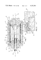
- FIG. 1 is a longitudinal sectional view of a heated roll of the present invention
- FIG. 2 is an enlarged partial sectional view of a portion of FIG. 1;
- FIG. 3 is a cross sectional view taken along lines 3--3 of FIG. 1, and
- FIG. 4 is a view of a typical PRIOR ART heated roll.
- a roll member generally designated at 10, being 1/2 of a roll couple, the other roll not being shown.
- Typical environments of the roll of the present invention are a steel surfaced embossing roll mating with a rubber covered roll for the embossing of a paper web, or as a hard surface calender roll mating with a similar roll for the production of polymeric films or webs. While the roll 10 of the present invention may advantageously be used in these environments, it will be understood that certain features of the invention may be utilized in other arrangements, or for other purposes (as, for cooling instead of heating). For purposes of this disclosure, the roll 10 will be described as used in an embossing operation of a polymeric web.
- the roll 10 is provided with an outer shell 12 having outer embossing surface 14, and an inner shell 16, the shells 12 and 16 being coaxially mounted for rotation about longitudinal axis 18.
- the shells 12 and 16 are tubular members enclosed at their ends by head members 20 and 22.
- Each of the head members 20, 22 carry journals 24 and 26 to be supported in bearings for rotatively carrying the roll 10.
- At least one of the head members 20, 22 is provided with conventional drive means (not shown herein) to rotate the roll member 10 about axis 18.
- Oil circulation means 28 may be advantageously connected to one head member 22, while the drive means may be affixed to the other head member 20. Alternatively, one of the oil circulation means 28 (either inlet or outlet) and the drive means may be affixed to the same head member.
- the outer shell 12 is provided with an inner surface 30 closely associated with an outer surface 40 of the inner shell 16.
- An annular chamber 42 is produced therebetween which extends the width of the roll member 10 between head members 20 and 22.
- the outer shell 12 is seated to the head members 20, 22 at 44, as with bolts, and the inner shell 16 is likewise affixed to the head members 20, 22 at 46.
- Heating fluid is supplied to the annular chamber 42 through inlet conduit 48, through an axial passageway 50 within inner shell 16, and through a radial inlet passageway 52 defined by the head member 20 and end portion 54 of inner shell 16. Fluid passing through passageway 50 impinges on head member 20 and is deflected radially in all directions within inlet passageway 52 toward the annular chamber 42 which surrounds inner shell 16.
- Fluid is returned to a heating member (not shown) from annular chamber 42 through radial outlet passageway 56 defined by head member 22 and the end portion 58 of inner shell 16 opposite end portion 54. Fluid is removed from the roll member 10 through outlet conduit 60, to be reheated and reintroduced to the roll 10.
- Heating fluid is directed into and out of the annular chamber 42 through apertures, here generally designated 62, which are formed through the inner shell 16 radially adjacent the passageways 52 and 56.
- apertures may take any convenient form, but a configuration found to have especially good performance characteristics is described hereinafter.
- the aperture 62 through inner shell 16 is a circular hole 64 drilled through the inner shell at the location of a circumferential groove 66 which is milled around the outer surface of shell 16.
- the groove 66 is preferably provided with sidewalls angled as shown in FIG. 2, with the radial axis of groove 66 offset from the radial axis of hole 64, so that oil may flow circumferentially in groove 66 between lip portion 68 and flow diverting means 70.
- Flow diverting means 70 is affixed to the inner shell 16, the means 70 being in the form of a circumferential band 72 as shown in FIG. 3, or as individual means associated with each aperture 62.
- the apertures 62 are aligned radially about the circumference of the inner shell 16 at the location of circumferential groove 66 at each end, radially adjacent passageways 52 and 56, so that the means 70 essentially encloses groove 66.
- a single pass, axial flow heated roll as in the present invention must be accomplished with a flow rate of heating fluid great enough to supply the total heat required by the roll without the fluid temperature being reduced at the outflow end by more than a predetermined allowable increment over the temperature at the inlet.
- a flow rate of heating fluid great enough to supply the total heat required by the roll without the fluid temperature being reduced at the outflow end by more than a predetermined allowable increment over the temperature at the inlet.
- a flow rate of heating fluid great enough to supply the total heat required by the roll without the fluid temperature being reduced at the outflow end by more than a predetermined allowable increment over the temperature at the inlet.
- the heating fluid 74 is contained within the inner shell 76, from which it flows through apertures 78 to the annulus 80 between the inner shell 76 and outer shell 82.
- the fluid 74 flows through an aperture 78 and impinges directly upon the inner surface of the outer shell 82, as at 84, resulting in heat transfer from the fluid to the roll surface being greatest where the fluid impinges on the outer shell (indicated by crosshatching).
- Areas of converging flow 88 produce adjacent "cold spots" 90 on the roll surface due to their low velocity and poor heat transfer characteristics. This pattern of hot and cold spots on the roll surface has obvious deleterious effects on web embossing or calendering.
- a further factor which may inhibit effective heat transfer from oil to roll surface is ineffective flow characteristics of the fluid upon entering the annulus. Optimal heat transfer will occur under fully turbulent flow, therefore the sooner this is obtained the more uniform will be the temperature profile across the roll width.
- Most heated rolls of which the applicant is aware have either inadequate turbulence upon entry to the heat distribution portion of the roll, or highly turbulent sites which transition toward a laminar state upon moving axially across the roll width. The former situation results in an increasing rate of heating across the roll width, and the latter results in a decreasing rate of heating or in local hot and cold zones as previously mentioned. Therefore, a roll having turbulent entry characteristics which develops and maintains uniform turbulence across the roll width is needed.
- a representative roll 10 embodying the present invention may be constructed with an outer shell 12 having a 24 inch outside diameter, a 118 inch width and a 3 inch thickness.
- the inner shell 16 is machined to provide a uniform annular chamber 42 of 0.25 inches, a dimension large enough so that deflection of the outer shell will have no significant effect on flow within the annulus.
- Aperture 62 is especially constructed to produce a desired level of turbulence in the heating fluid (oil) entering the annulus 42.
- a "control orifice" 92 is produced, as shown in FIG. 2, by a wall 94 of the portion 66 of aperture 62, and by flow diverting means 70. This control orifice 92 forces the oil to enter the annulus 42 at an acute angle to the outer shell 12, rather than impinging perpendicularly on the inner surface 30 of the outer shell 12.
- oil is provided with a design flow of 300 gallons per minute and a kinematic viscosity of 0.015 ft 2 /second.
- the Reynolds' number for the annular flow therefore is 17,500, considerably in excess of the lower critical of 2,000 needed for transition to turblulent flow. Therefore, a high coefficient of heat transfer will be obtained and maintained in the annulus.
- the throat of the control orifice 92 is made approximately 75% the width of the annular opening 42, producing an orifice velocity 1/3 greater than the mean velocity in the annulus 42. Oil flowing through the orifice undergoes an abrupt expansion as it enters the annulus, resulting in a loss of velocity. This loss of velocity is one indicator of the energy expended in turbulence and can be related to the corresponding friction loss in the annulus per unit distance.
- the energy expended in turbulent agitation at the orifice is equal to the energy expended in turbulence in a 1 inch length of the annulus, an appropriate level of initial turbulence at the orifice exit to assure nearly uniform heat transfer across the annulus
- the plurality of control orifices 92 distribute oil flowing into the annulus 42 evenly around the perimeter of the roll, oil velocity upstream from the orifice should be less than the oil velocity in the orifice, i.e., the area for flow should be larger upstream from the orifice. Therefore, for a roll with the dimensions as described above, 48 apertures 62 are provided with portion 64 having a 5/8 inch diameter and the circumferential groove 66 being 1/4 inch deep and having a 1 inch diameter.
- the passageway 50 may be provided with a 4 inch inside diameter and the passageways 52 and 56 with a flow area of 26 square inches each at the radius of the aperture 62.
- the first control in distributing flow uniformly results from the acceleration (and resulting pressure drop) from the inlet passageway 52 (which functions as a "stilling chamber") to the 48 apertures 64.
- the flow of oil is deflected from the radial direction to both circumferential (within groove 66) and axial, assuring uniform distribution circumferentially around the annulus 42.
- the corner 96 where flow "turns" to axial to enter the annulus 42 is preferably rounded (FIG. 2) to prevent flow separation, and causes the fluid to follow the outer surface 40 of the inner shell 16.
- Oil from apertures flow circumferentially within groove 66 in both directions and impinges on flow from adjacent apertures moving in the opposite direction, providing a continuous supply of oil to the control orifice where the direction of flow changes from circumferential to axial flow.
- outlet apertures 62A equal in number and dimension to inlet apertures 62, each aperture located in a circumferential groove 66A and being provided with a flow diverting means 70A.
- a heated roll as shown in FIG. 1 may be one roll of a mated couple, with the other roll being identical in all respects except the oil inlet and outlet means are reversed, so that oil flows into the roll through conduit 60, passageway 56 and apertures 62A. Axial flow is reversed and oil exits through apertures 62, passageway 52 and conduit 48. In this manner, the mated roll couple will expand equally on opposite ends for a more uniform fit.
Landscapes
- Engineering & Computer Science (AREA)
- Mechanical Engineering (AREA)
- General Engineering & Computer Science (AREA)
- Textile Engineering (AREA)
- Physics & Mathematics (AREA)
- Thermal Sciences (AREA)
- Rolls And Other Rotary Bodies (AREA)
- Paper (AREA)
- Yarns And Mechanical Finishing Of Yarns Or Ropes (AREA)
- Shaping Of Tube Ends By Bending Or Straightening (AREA)
Priority Applications (11)
| Application Number | Priority Date | Filing Date | Title |
|---|---|---|---|
| US06/128,408 US4252184A (en) | 1980-03-10 | 1980-03-10 | Control of oil distribution in heated embossing rolls |
| CA000372519A CA1171077A (en) | 1980-03-10 | 1981-03-09 | Control of oil distribution in heated embossing rolls |
| DE3108859A DE3108859C2 (de) | 1980-03-10 | 1981-03-09 | Beheizte Doppelmantelwalze |
| KR1019810000756A KR840000555B1 (ko) | 1980-03-10 | 1981-03-09 | 가열로울러 |
| BR8101361A BR8101361A (pt) | 1980-03-10 | 1981-03-09 | Rolo aquecido para ser usado em maquina de fabricar papel ou semelhante e processo para aquecer o dito rolo |
| GB8107346A GB2071276B (en) | 1980-03-10 | 1981-03-09 | Heated or cooled rollers |
| JP3447881A JPS56144291A (en) | 1980-03-10 | 1981-03-10 | Heat roller |
| AU68202/81A AU540985B2 (en) | 1980-03-10 | 1981-03-10 | Heated embossing roller |
| IT47991/81A IT1142763B (it) | 1980-03-10 | 1981-03-10 | Dispositivo di controllo della distribuzione dell'olio in cilindri riscaldati per goffratura |
| NL8101139A NL8101139A (nl) | 1980-03-10 | 1981-03-10 | Regeling van de olieverdeling in verwarmde drijfwerkrollen. |
| FR8104735A FR2477597A1 (fr) | 1980-03-10 | 1981-03-10 | Structure de rouleau pour machine a papier et son procede de chauffage |
Applications Claiming Priority (1)
| Application Number | Priority Date | Filing Date | Title |
|---|---|---|---|
| US06/128,408 US4252184A (en) | 1980-03-10 | 1980-03-10 | Control of oil distribution in heated embossing rolls |
Publications (1)
| Publication Number | Publication Date |
|---|---|
| US4252184A true US4252184A (en) | 1981-02-24 |
Family
ID=22435240
Family Applications (1)
| Application Number | Title | Priority Date | Filing Date |
|---|---|---|---|
| US06/128,408 Expired - Lifetime US4252184A (en) | 1980-03-10 | 1980-03-10 | Control of oil distribution in heated embossing rolls |
Country Status (11)
| Country | Link |
|---|---|
| US (1) | US4252184A (de) |
| JP (1) | JPS56144291A (de) |
| KR (1) | KR840000555B1 (de) |
| AU (1) | AU540985B2 (de) |
| BR (1) | BR8101361A (de) |
| CA (1) | CA1171077A (de) |
| DE (1) | DE3108859C2 (de) |
| FR (1) | FR2477597A1 (de) |
| GB (1) | GB2071276B (de) |
| IT (1) | IT1142763B (de) |
| NL (1) | NL8101139A (de) |
Cited By (39)
| Publication number | Priority date | Publication date | Assignee | Title |
|---|---|---|---|---|
| US4440214A (en) * | 1980-05-30 | 1984-04-03 | Beloit Corporation | Heat transfer roll and method |
| WO1984002573A1 (en) * | 1982-12-20 | 1984-07-05 | Skandinaviska Apparatind | A rotating heat exchanger |
| US4506727A (en) * | 1982-06-14 | 1985-03-26 | Usm Corporation | Converted temperature control roll |
| EP0158220A2 (de) * | 1984-04-06 | 1985-10-16 | Walzen Irle GmbH | Mittels eines Wärme übertragenden Mediums beheizbare Kalanderwalze |
| US4693015A (en) * | 1985-08-26 | 1987-09-15 | Hercules Incorporated | Direct fired cylinder dryer |
| US4710271A (en) * | 1986-04-08 | 1987-12-01 | Ray R. Miller | Belt and drum-type press |
| US4717338A (en) * | 1985-04-12 | 1988-01-05 | Cellier S.A. | Heater drum for manufacturing process |
| US4758310A (en) * | 1986-04-08 | 1988-07-19 | Miller Ray R | Belt and drum-type pressing apparatus |
| US4781795A (en) * | 1986-04-08 | 1988-11-01 | Ray R. Miller | Heated drum having high thermal flux and belt press using same |
| FR2628830A1 (fr) * | 1988-03-18 | 1989-09-22 | Beugras Herve | Dispositif diffuseur pour circuit d'echange a courants croises avec une paroi d'echange mobile ou fixe |
| US4899811A (en) * | 1988-01-28 | 1990-02-13 | J. M. Voith Gmbh | Cooling roll |
| US4949475A (en) * | 1989-12-20 | 1990-08-21 | Beloit Corporation | Temperature compensated ventilating roll |
| EP0411427A2 (de) * | 1989-08-01 | 1991-02-06 | Eduard Küsters Maschinenfabrik GmbH & Co. KG | Walze zur Druck- und Temperaturbehandlung von bahnförmigem Material |
| DE4022334A1 (de) * | 1990-07-13 | 1992-01-16 | Voith Gmbh J M | Walze mit gummi- oder kautschukelastischem mantel bei streich- oder sonstigen beschichtungseinrichtungen der papierindustrie |
| US5131323A (en) * | 1989-03-20 | 1992-07-21 | Hermann Siebert | Packing sheet calender |
| FR2685458A1 (fr) * | 1991-12-19 | 1993-06-25 | Darlet Marchante Tech Sa | Tambour pour le refroidissement de produits en feuille ou plaque. |
| US5271456A (en) * | 1989-05-22 | 1993-12-21 | Felix Baumann | Drying cylinders in plant for manufacturing cardboard, paper |
| WO1999031331A1 (de) * | 1997-12-12 | 1999-06-24 | Klöber, Johannes | Vorrichtung und verfahren zur herstellung einer diffusionsoffenen unterspannbahn |
| US5984658A (en) * | 1996-02-09 | 1999-11-16 | Modern Machinery Co., Ltd. | Thin sheet forming roll, sheet forming machine, and sheet forming method |
| EP0959257A1 (de) * | 1998-05-19 | 1999-11-24 | Voith Sulzer Papiertechnik Patent GmbH | Kalanderwalze |
| US6161302A (en) * | 1996-02-16 | 2000-12-19 | Rantala; Pekka | Dryer apparatus for fiber webs |
| US6675876B2 (en) * | 1999-12-01 | 2004-01-13 | Sasakura Engineering Co., Ltd. | Rotary cooling roller |
| US6683284B2 (en) | 2002-03-22 | 2004-01-27 | Metso Paper Karlstad Ab | Thermal roll for papermaking with a fluid circulation system and method therefor |
| US6810800B1 (en) * | 1999-10-08 | 2004-11-02 | Koenig & Bauer Aktiengesellschaft | Cylinder for a rotary press |
| US6913673B2 (en) | 2001-12-19 | 2005-07-05 | Kimberly-Clark Worldwide, Inc. | Heated embossing and ply attachment |
| US7025123B1 (en) | 1999-01-29 | 2006-04-11 | Kimberly-Clark Worldwide, Inc. | Fluid distribution system for thermal transfer rollers |
| US7031626B1 (en) * | 2003-03-28 | 2006-04-18 | Eastman Kodak Company | Fixing roller system and method |
| US20070062405A1 (en) * | 2005-09-10 | 2007-03-22 | Man Roland Druckmaschinen Ag | Press cylinder and method for compensating thermally induced deformation of a press cylinder |
| US20070294914A1 (en) * | 2005-01-05 | 2007-12-27 | Rainer Kloibhofer | Drying cylinder |
| US20080005921A1 (en) * | 2005-01-05 | 2008-01-10 | Thomas Gruber-Nadlinger | Device and method for producing and/or finishing a web of fibrous material |
| WO2009127399A1 (de) * | 2008-04-18 | 2009-10-22 | Leonhard Kurz Stiftung & Co. Kg | Beheizte prägewalze |
| US8211078B2 (en) | 2005-02-17 | 2012-07-03 | The Procter And Gamble Company | Sanitary napkins capable of taking complex three-dimensional shape in use |
| CN105328979A (zh) * | 2015-11-27 | 2016-02-17 | 佛山市南海区三简包装有限公司 | 一种新型模压版辊 |
| US9579238B2 (en) | 2005-02-17 | 2017-02-28 | The Procter & Gamble Company | Sanitary napkins capable of taking complex three-dimensional shape in use |
| CN106949762A (zh) * | 2017-03-20 | 2017-07-14 | 连云港鹰游工程技术研究院有限公司 | 一种热辊轴向传热技术 |
| CN109594400A (zh) * | 2019-01-24 | 2019-04-09 | 安徽紫竹林纸业有限公司 | 一种纸张加工过程中纸张平滑压光装置 |
| US10563299B2 (en) * | 2015-11-20 | 2020-02-18 | Sumitomo Chemical Company, Limited | Heating roller and film production method |
| CN111733468A (zh) * | 2020-07-16 | 2020-10-02 | 无锡中力科技有限公司 | 一种高速旋转梯度热管式热辊及其加工方法 |
| WO2023280722A1 (en) | 2021-07-05 | 2023-01-12 | Körber Tissue S.p.A. | Embossing device with at least one heated embossing roller, and method |
Families Citing this family (6)
| Publication number | Priority date | Publication date | Assignee | Title |
|---|---|---|---|---|
| JPS63136921U (de) * | 1987-03-02 | 1988-09-08 | ||
| DE3926918A1 (de) * | 1989-08-16 | 1991-02-21 | Wolfgang Wagner | Vorrichtung zum praegen von reliefmustern auf einem kontinuierlich zufuehrbaren informationstraeger |
| NO179727C (no) * | 1994-02-21 | 1996-12-04 | Kvaerner Eureka As | Fremgangsmåte ved oppvarming av en mantel-arbeidsflate på en roterende valse, samt en roterbar valse |
| DE19509863A1 (de) * | 1995-03-17 | 1996-04-11 | Peter H Meier | Verfahren und Vorrichtung zur Verformung von Papier und Karton |
| DE29510512U1 (de) * | 1995-06-29 | 1996-10-31 | Kuesters Eduard Maschf | Beheizbare Walze |
| KR102642399B1 (ko) | 2022-02-23 | 2024-03-04 | 주식회사 일진엠앤씨 | 열매체유 순환방식의 히팅롤러 장치 |
Citations (6)
| Publication number | Priority date | Publication date | Assignee | Title |
|---|---|---|---|---|
| GB503630A (en) * | 1937-10-30 | 1939-04-12 | William George Simon | Improvements in or relating to heating, cooling or drying cylinders or drums |
| US2677899A (en) * | 1951-05-16 | 1954-05-11 | Pusey & Jones Corp | Jacketed steam drier |
| US3838734A (en) * | 1973-01-22 | 1974-10-01 | Beloit Corp | Heat transfer roll body |
| US4050510A (en) * | 1973-04-27 | 1977-09-27 | Helmuth Theysohn | Calender heating roll |
| US4069594A (en) * | 1975-08-06 | 1978-01-24 | Sulzer Brothers Limited | Drying cylinder |
| US4077466A (en) * | 1974-10-23 | 1978-03-07 | Vepa Ag | Heated roll, such as a godet, in drawing units, for example |
-
1980
- 1980-03-10 US US06/128,408 patent/US4252184A/en not_active Expired - Lifetime
-
1981
- 1981-03-09 GB GB8107346A patent/GB2071276B/en not_active Expired
- 1981-03-09 CA CA000372519A patent/CA1171077A/en not_active Expired
- 1981-03-09 KR KR1019810000756A patent/KR840000555B1/ko active
- 1981-03-09 DE DE3108859A patent/DE3108859C2/de not_active Expired
- 1981-03-09 BR BR8101361A patent/BR8101361A/pt unknown
- 1981-03-10 NL NL8101139A patent/NL8101139A/nl not_active Application Discontinuation
- 1981-03-10 FR FR8104735A patent/FR2477597A1/fr not_active Withdrawn
- 1981-03-10 AU AU68202/81A patent/AU540985B2/en not_active Ceased
- 1981-03-10 IT IT47991/81A patent/IT1142763B/it active
- 1981-03-10 JP JP3447881A patent/JPS56144291A/ja active Pending
Patent Citations (6)
| Publication number | Priority date | Publication date | Assignee | Title |
|---|---|---|---|---|
| GB503630A (en) * | 1937-10-30 | 1939-04-12 | William George Simon | Improvements in or relating to heating, cooling or drying cylinders or drums |
| US2677899A (en) * | 1951-05-16 | 1954-05-11 | Pusey & Jones Corp | Jacketed steam drier |
| US3838734A (en) * | 1973-01-22 | 1974-10-01 | Beloit Corp | Heat transfer roll body |
| US4050510A (en) * | 1973-04-27 | 1977-09-27 | Helmuth Theysohn | Calender heating roll |
| US4077466A (en) * | 1974-10-23 | 1978-03-07 | Vepa Ag | Heated roll, such as a godet, in drawing units, for example |
| US4069594A (en) * | 1975-08-06 | 1978-01-24 | Sulzer Brothers Limited | Drying cylinder |
Cited By (51)
| Publication number | Priority date | Publication date | Assignee | Title |
|---|---|---|---|---|
| US4440214A (en) * | 1980-05-30 | 1984-04-03 | Beloit Corporation | Heat transfer roll and method |
| US4506727A (en) * | 1982-06-14 | 1985-03-26 | Usm Corporation | Converted temperature control roll |
| WO1984002573A1 (en) * | 1982-12-20 | 1984-07-05 | Skandinaviska Apparatind | A rotating heat exchanger |
| US4582128A (en) * | 1982-12-20 | 1986-04-15 | Skandinaviska Apparatindustri Ab | Rotating heat exchanger |
| EP0158220A2 (de) * | 1984-04-06 | 1985-10-16 | Walzen Irle GmbH | Mittels eines Wärme übertragenden Mediums beheizbare Kalanderwalze |
| EP0158220A3 (en) * | 1984-04-06 | 1986-03-12 | Walzen Irle Gmbh | Calander roll heated by a heat-transfer fluid |
| US4717338A (en) * | 1985-04-12 | 1988-01-05 | Cellier S.A. | Heater drum for manufacturing process |
| US4693015A (en) * | 1985-08-26 | 1987-09-15 | Hercules Incorporated | Direct fired cylinder dryer |
| US4710271A (en) * | 1986-04-08 | 1987-12-01 | Ray R. Miller | Belt and drum-type press |
| US4758310A (en) * | 1986-04-08 | 1988-07-19 | Miller Ray R | Belt and drum-type pressing apparatus |
| US4781795A (en) * | 1986-04-08 | 1988-11-01 | Ray R. Miller | Heated drum having high thermal flux and belt press using same |
| US4899811A (en) * | 1988-01-28 | 1990-02-13 | J. M. Voith Gmbh | Cooling roll |
| FR2628830A1 (fr) * | 1988-03-18 | 1989-09-22 | Beugras Herve | Dispositif diffuseur pour circuit d'echange a courants croises avec une paroi d'echange mobile ou fixe |
| US5131323A (en) * | 1989-03-20 | 1992-07-21 | Hermann Siebert | Packing sheet calender |
| US5271456A (en) * | 1989-05-22 | 1993-12-21 | Felix Baumann | Drying cylinders in plant for manufacturing cardboard, paper |
| EP0411427A2 (de) * | 1989-08-01 | 1991-02-06 | Eduard Küsters Maschinenfabrik GmbH & Co. KG | Walze zur Druck- und Temperaturbehandlung von bahnförmigem Material |
| EP0411427A3 (en) * | 1989-08-01 | 1991-09-11 | Eduard Kuesters Maschinenfabrik Gmbh & Co. Kg | Roll for heat and pressure treatment of web material |
| US4949475A (en) * | 1989-12-20 | 1990-08-21 | Beloit Corporation | Temperature compensated ventilating roll |
| DE4022334A1 (de) * | 1990-07-13 | 1992-01-16 | Voith Gmbh J M | Walze mit gummi- oder kautschukelastischem mantel bei streich- oder sonstigen beschichtungseinrichtungen der papierindustrie |
| FR2685458A1 (fr) * | 1991-12-19 | 1993-06-25 | Darlet Marchante Tech Sa | Tambour pour le refroidissement de produits en feuille ou plaque. |
| US5984658A (en) * | 1996-02-09 | 1999-11-16 | Modern Machinery Co., Ltd. | Thin sheet forming roll, sheet forming machine, and sheet forming method |
| US6161302A (en) * | 1996-02-16 | 2000-12-19 | Rantala; Pekka | Dryer apparatus for fiber webs |
| WO1999031331A1 (de) * | 1997-12-12 | 1999-06-24 | Klöber, Johannes | Vorrichtung und verfahren zur herstellung einer diffusionsoffenen unterspannbahn |
| EP0959257A1 (de) * | 1998-05-19 | 1999-11-24 | Voith Sulzer Papiertechnik Patent GmbH | Kalanderwalze |
| US7025123B1 (en) | 1999-01-29 | 2006-04-11 | Kimberly-Clark Worldwide, Inc. | Fluid distribution system for thermal transfer rollers |
| US6810800B1 (en) * | 1999-10-08 | 2004-11-02 | Koenig & Bauer Aktiengesellschaft | Cylinder for a rotary press |
| US6675876B2 (en) * | 1999-12-01 | 2004-01-13 | Sasakura Engineering Co., Ltd. | Rotary cooling roller |
| US20050241788A1 (en) * | 2001-12-19 | 2005-11-03 | Baggot James L | Heated embossing and ply attachment |
| US6913673B2 (en) | 2001-12-19 | 2005-07-05 | Kimberly-Clark Worldwide, Inc. | Heated embossing and ply attachment |
| US6683284B2 (en) | 2002-03-22 | 2004-01-27 | Metso Paper Karlstad Ab | Thermal roll for papermaking with a fluid circulation system and method therefor |
| US7031626B1 (en) * | 2003-03-28 | 2006-04-18 | Eastman Kodak Company | Fixing roller system and method |
| US7802377B2 (en) * | 2005-01-05 | 2010-09-28 | Voith Patent Gmbh | Drying cylinder |
| US20070294914A1 (en) * | 2005-01-05 | 2007-12-27 | Rainer Kloibhofer | Drying cylinder |
| US20080005921A1 (en) * | 2005-01-05 | 2008-01-10 | Thomas Gruber-Nadlinger | Device and method for producing and/or finishing a web of fibrous material |
| US8702668B2 (en) | 2005-02-17 | 2014-04-22 | The Procter And Gamble Company | Sanitary napkins capable of taking complex three-dimensional shape in use |
| US9579238B2 (en) | 2005-02-17 | 2017-02-28 | The Procter & Gamble Company | Sanitary napkins capable of taking complex three-dimensional shape in use |
| US10568781B2 (en) | 2005-02-17 | 2020-02-25 | The Procter & Gamble Company | Sanitary napkins capable of taking complex three-dimensional shape in use |
| US8211078B2 (en) | 2005-02-17 | 2012-07-03 | The Procter And Gamble Company | Sanitary napkins capable of taking complex three-dimensional shape in use |
| US20070062405A1 (en) * | 2005-09-10 | 2007-03-22 | Man Roland Druckmaschinen Ag | Press cylinder and method for compensating thermally induced deformation of a press cylinder |
| US7568428B2 (en) * | 2005-09-10 | 2009-08-04 | Man Roland Druckmaschinen Ag | Press cylinder and method for compensating thermally induced deformation of a press cylinder |
| WO2009127399A1 (de) * | 2008-04-18 | 2009-10-22 | Leonhard Kurz Stiftung & Co. Kg | Beheizte prägewalze |
| TWI467098B (zh) * | 2008-04-18 | 2015-01-01 | Leonhard Kurz Stiftung & Co Kg | 受加熱之鐫印滾子 |
| RU2486304C2 (ru) * | 2008-04-18 | 2013-06-27 | Леонхард Курц Штифтунг Унд Ко. Кг | Тиснильный валик с обогревом |
| US10563299B2 (en) * | 2015-11-20 | 2020-02-18 | Sumitomo Chemical Company, Limited | Heating roller and film production method |
| CN105328979A (zh) * | 2015-11-27 | 2016-02-17 | 佛山市南海区三简包装有限公司 | 一种新型模压版辊 |
| CN105328979B (zh) * | 2015-11-27 | 2017-11-14 | 佛山市南海区三简包装有限公司 | 一种新型模压版辊 |
| CN106949762A (zh) * | 2017-03-20 | 2017-07-14 | 连云港鹰游工程技术研究院有限公司 | 一种热辊轴向传热技术 |
| CN109594400A (zh) * | 2019-01-24 | 2019-04-09 | 安徽紫竹林纸业有限公司 | 一种纸张加工过程中纸张平滑压光装置 |
| CN111733468A (zh) * | 2020-07-16 | 2020-10-02 | 无锡中力科技有限公司 | 一种高速旋转梯度热管式热辊及其加工方法 |
| CN111733468B (zh) * | 2020-07-16 | 2024-02-09 | 无锡中力科技有限公司 | 一种高速旋转梯度热管式热辊及其加工方法 |
| WO2023280722A1 (en) | 2021-07-05 | 2023-01-12 | Körber Tissue S.p.A. | Embossing device with at least one heated embossing roller, and method |
Also Published As
| Publication number | Publication date |
|---|---|
| AU6820281A (en) | 1981-09-17 |
| NL8101139A (nl) | 1981-10-01 |
| CA1171077A (en) | 1984-07-17 |
| DE3108859A1 (de) | 1982-01-28 |
| KR840000555B1 (ko) | 1984-04-20 |
| BR8101361A (pt) | 1981-09-15 |
| IT1142763B (it) | 1986-10-15 |
| AU540985B2 (en) | 1984-12-13 |
| GB2071276B (en) | 1983-04-20 |
| JPS56144291A (en) | 1981-11-10 |
| GB2071276A (en) | 1981-09-16 |
| IT8147991A0 (it) | 1981-03-10 |
| DE3108859C2 (de) | 1985-05-15 |
| KR830005440A (ko) | 1983-08-13 |
| FR2477597A1 (fr) | 1981-09-11 |
Similar Documents
| Publication | Publication Date | Title |
|---|---|---|
| US4252184A (en) | Control of oil distribution in heated embossing rolls | |
| US4757582A (en) | Roll with heated mantle and method | |
| US4955268A (en) | Apparatus containing a work surface heated with a heat carrier medium | |
| US6039681A (en) | Heating roll | |
| US4282638A (en) | Controlled deflection roll | |
| JPH0217211A (ja) | 加熱可能なロール | |
| US4274210A (en) | Gas nozzle for use in treating material webs | |
| CA1240186A (en) | Fluid-medium-heated calender roll | |
| CA2002914C (en) | Heating or cooling roller | |
| FI82275C (fi) | Foerfarande och anordning foer reglering av tjockleken hos ett banmaterial som gaor genom en nip. | |
| CA1171078A (en) | Heat transfer roll and method | |
| US7452447B2 (en) | Steam distributor for steam showers | |
| US5383833A (en) | Roll for heating or cooling running webs | |
| US3838734A (en) | Heat transfer roll body | |
| USRE25927E (en) | Drying drum amd method | |
| JPH0337441B2 (de) | ||
| US5022965A (en) | Method and device in a head box of a paper machine for controlling distribution of fiber orientation in a paper web | |
| CA2191003C (en) | Lubrication of a roll jacket of a press roller | |
| US6413470B1 (en) | Device for guiding bands in a suspended manner | |
| US7025123B1 (en) | Fluid distribution system for thermal transfer rollers | |
| GB2226101A (en) | A press roll for treating web material, such as paper | |
| EP0362241A1 (de) | Strömungsregelung für kühlmittel. | |
| US4093023A (en) | Sheet mill table roll | |
| CA1286901C (en) | Air shower apparatus and method | |
| US4899811A (en) | Cooling roll |
Legal Events
| Date | Code | Title | Description |
|---|---|---|---|
| STCF | Information on status: patent grant |
Free format text: PATENTED CASE |