US4030652A - Equalizing device for movements in packing machines, especially machines for making bags and the like - Google Patents
Equalizing device for movements in packing machines, especially machines for making bags and the like Download PDFInfo
- Publication number
- US4030652A US4030652A US05/673,421 US67342176A US4030652A US 4030652 A US4030652 A US 4030652A US 67342176 A US67342176 A US 67342176A US 4030652 A US4030652 A US 4030652A
- Authority
- US
- United States
- Prior art keywords
- rollers
- roller
- withdrawing
- packing material
- equalizing
- Prior art date
- Legal status (The legal status is an assumption and is not a legal conclusion. Google has not performed a legal analysis and makes no representation as to the accuracy of the status listed.)
- Expired - Lifetime
Links
Images


Classifications
-
- B—PERFORMING OPERATIONS; TRANSPORTING
- B65—CONVEYING; PACKING; STORING; HANDLING THIN OR FILAMENTARY MATERIAL
- B65H—HANDLING THIN OR FILAMENTARY MATERIAL, e.g. SHEETS, WEBS, CABLES
- B65H20/00—Advancing webs
- B65H20/24—Advancing webs by looping or like devices
-
- B—PERFORMING OPERATIONS; TRANSPORTING
- B65—CONVEYING; PACKING; STORING; HANDLING THIN OR FILAMENTARY MATERIAL
- B65H—HANDLING THIN OR FILAMENTARY MATERIAL, e.g. SHEETS, WEBS, CABLES
- B65H23/00—Registering, tensioning, smoothing or guiding webs
- B65H23/04—Registering, tensioning, smoothing or guiding webs longitudinally
- B65H23/16—Registering, tensioning, smoothing or guiding webs longitudinally by weighted or spring-pressed movable bars or rollers
-
- B—PERFORMING OPERATIONS; TRANSPORTING
- B31—MAKING ARTICLES OF PAPER, CARDBOARD OR MATERIAL WORKED IN A MANNER ANALOGOUS TO PAPER; WORKING PAPER, CARDBOARD OR MATERIAL WORKED IN A MANNER ANALOGOUS TO PAPER
- B31B—MAKING CONTAINERS OF PAPER, CARDBOARD OR MATERIAL WORKED IN A MANNER ANALOGOUS TO PAPER
- B31B70/00—Making flexible containers, e.g. envelopes or bags
- B31B70/02—Feeding or positioning sheets, blanks or webs
- B31B70/10—Feeding or positioning webs
Definitions
- the present invention relates to a compensating device for compensating movements in packing machines, especially in machines for making bags and the like, which is arranged between a first continuously operating withdrawing device for foil-shaped wrapping materials, and a second intermittently operating withdrawing device and which comprises a spring urged pivot lever as well as a stationary carrier respectively equipped with a plurality of rotatably journalled guiding rollers arranged in spaced relationship to and one behind the other while the wrapping material is passed in loops respectively about guiding rollers of the pivot lever and a guiding roller of the carrier.
- Compensating devices of this type are described for instance in German Offenlegungsschrift Nos. 1,704,187 and 1,942,410.
- the paper, viscous foil (Zellglas) or metal foil is withdrawn continuously from a supply roll and is conveyed to a processing station intermittently or pulse-wise.
- a compensating device for compensating or equalizing movements is arranged between a first continuously operating withdrawing device and a second intermediately operating withdrawing device.
- the said compensating device with heretofore known wrapping machines as disclosed for instance in German Offenlegungsschrift Nos. 1,704,187 and 1,942,410 comprises a stationary roller arrangement and a roller arrangement which is mounted on a spring actuated oscillating or pivot lever.
- Said last mentioned roller arrangement comprises a plurality of serially arranged and mutually spaced guiding rollers which are rotatably journalled.
- an object of the present invention to improve a movement compensating device of the above mentioned general type so that also at higher withdrawing speeds of the wrapping material, especially during the starting phase of the wrapping machine, a jerk-free conveying movement of the wrapping material will be assured.
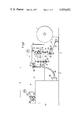
- FIG. 1 is a side view of a wrapping machine with a compensating device according to the invention.
- FIG. 2 is a diagrammatic illustration of a movement compensating device according to the invention with stroke and speed vectors for the wrapping material which in the form of loops passes through the movement compensating device.
- FIG. 3 represents a diagrammatic illustration similar to that of FIG. 2 but for a heretofore known movement compensating device.
- the compensating device is characterized primarily in that the distance between each two adjacent guiding rollers of the oscillating lever are different in length.
- the present invention is based on the finding that the arrangement of the rollers on the oscillating lever at equal distances from each other is the cause for the above mentioned jerky movements at higher withdrawing speeds. Based on this finding, with the movement compensating device according to the invention, the mutual distances of adjacent guiding rollers of the oscillating lever have been selected of different lengths. According to a preferred embodiment of the invention, the distance between adjacent guiding rollers increases in the withdrawing direction of the wrapping material.
- a ⁇ 2 n indicates the distance between the first and second guiding rollers of the oscillating lever when viewing in the direction of withdrawal of the wrapping material.
- the letter n indicates a whole number of the numbers 0,1,2,3,4, etc. which designates the order of the respective distance.
- the bag manufacturing machine 1 shown in FIG. 1 comprises a foundation 2 with a pair of lateral or side sections 3 and a pair of lateral sections 6 between which there is provided a chamber 4 and a bridge-like pair of side sections 5.
- the side sections 3 have rotatably mounted thereon a supply roller 7 for the wrapping material to be processed, especially a foil 8 of synthetic material.
- the foil 8 of synthetic material is by means of a first continuously operating withdrawing device 9 drawn off over rollers 10, 11 and 12.
- the withdrawing device 9 comprises a first roller 13 which is driven by M 1 , an electric motor or hydraulic motor in a continuous manner and furthermore comprises a roller 14 which follows said first roller 13 and is rotatably journalled on a spring urged pivotal lever 15.
- the withdrawing device 9 feeds the foil 8 to the movement compensating device 16 according to the invention from where the foil 8 is withdrawn by means of a second intermittently or pulse-like operating second withdrawing device 17.
- the withdrawing device 17 is connected to the frame section 6 and comprises a roller pair 18, 19 which is driven by an intermittently operating driving system M 2 .
- the first roller 18 of said roller pair 18, 19 is driven and its second roller 19 is taken along by said first roller.
- a cutting device 20 for cutting off the foil 8 into equally long sections.
- the movement compensating device 16 comprises a first roller arrangement 21 which is rotatably journalled on the frame section 2, and also comprises a second roller arrangement 23 which is rotatably journalled on an oscillating lever 22.
- the first roller arrangement 21, according to the illustrated embodiment of the invention includes four serially arranged guiding rollers 24-27 which are spaced from each other at equal distances.
- the second roller arrangement 23 according to the exemplary illustration shown in the drawings includes three serially arranged guiding rollers 28, 29 and 30 which, however, are unequally spaced from each other.
- the oscillating lever 22 has one of its ends rotatably pivotally connected to the bearing pin 31 and has its other end connected to a return spring 32 which is suspended in an opening of the perforated plate 33.
- the oscillating movement of the oscillating lever 22 about the bearing pivot 31 is limited by two abutments 34 and 35.
- the foil 8 of synthetic material is looped around one guiding roller for instance 24, of the first stationary roller arrangement 21 and about one guiding roller for instance 28, of the second pivotable roller arrangement 23.
- a suction roller 36 is nonpivotally journalled on the frame plate 5.
- the suction openings 37 of said suction roller 36 are through a hose 38 connected to a vacuum pump 39.
- FIG. 2 shows the pivotable lever 22 which is pivotally connected to the bearing pivot 31 and the return spring 32.
- Lever 22 is pivoted out of its rest position 40 indicated by dot-dash lines, by an angle ⁇ .
- the guiding rollers 28, 29 and 30 are rotatably journalled on the pivotable lever 20.
- the pivot points of the guiding rollers 28-30 are spaced from the bearing pin 31 by the distances r 3 , r 2 and r 1 respectively.
- the distance r 1 -r 2 between the guiding rollers 30 and 29 is greater than the distance r 2 -r 3 between the guiding rollers 29 and 28.
- the distance between adjacent guiding rollers of the pivotable lever 22 thus increases in the withdrawing direction 41 of the foil 8 of synthetic material.
- the foil 8 is looped around one roller 24-27 of the first roller arrangement 21 and is looped around a guiding roller 28-30 of the second roller arrangement 23 journalled on the pivotable lever 22.
- roller 26 is according to FIG. 1 divided into two rollers 26a and 26b for reason of assuring a better tangential guiding of the foil of synthetic material with regard to the guiding rollers.
- the distance between adjacent guiding rollers of the second roller arrangement 23 meets in a preferred manner the relationship a ⁇ 2 n , wherein a designates the distance r 2 -r 3 between the centers of rotation of the first guiding roller 28 and the second guiding roller 29 and n indicates a whole number designating the order of the respective contemplated distance and selected from the row of numbers 0,1,2,3,4, . . . . In the contemplated example, n equals 1 so that the first distance, i.e. the distance between the centers of rotation of the guiding rollers 30 and 29 equals 2a.
- the vectors s 1 , s' 1 , s 2 , s' 2 , s 3 and s' 3 represent the movement of the webs of the foil 8 of synthetic material according to which the pivotable lever 22 moves by the angle ⁇ ⁇ to the position 42 indicated by dash lines.
- the velocity factors v 1 , v 2 and v 3 indicate the amount and direction of the movement of the centers of rotation of the respective guiding rollers 30, 29; 28.
- the amounts of the velocity vectors v 1 -v 3 correspond to the stoke performed by the center of rotation of the associated guiding roller 30, 29, 28 at a rotation of the pivotable lever 22 by the angle ⁇ ⁇ to the position 42.
- the ascertainment of the stroke vectors s 1 -s 3 as well as s' 1 -s' 3 is effected in the following manner: starting from the assumption which has been proven in practice that during the first withdrawing jerk of the foil 8, the foil section between the rollers 24 and 28 is not yet moved, the stroke vector s' 3 equals zero.
- the tip of the stroke vector s' 3 is, therefore located at the contacting point between the guiding roller 28 and that section of foil 8 which is located between the rollers 24 and 28. If a straight line is drawn from the tip of the stroke vector s' 3 to the tip of the stroke vector v 3 , this straight line will intersect with the section of foil 8 between the rollers 25 and 28 at the tip of the stroke vector s 3 .
- the stroke vector s 3 is ascertained graphically. Inasmuch as the length of the stroke vector s 3 equals the length of the stroke vector s' 2 , also the stroke vector s' 2 is directly ascertained therefrom. If now from the tip of the stroke vector s' 2 a straight line is drawn to the tip of the velocity vector v 2 , the point of intersection between this straight line and the section of foil 8 between the rollers 26a and 29 furnishes the tip of the stroke vector s 2 . Since the length of the stroke vector s 2 equals the length of the stroke vector s' 1 , immediately also the stroke vector s' 1 is obtained. The straight line between the tips of the vectors s' 1 and v 1 will by means of its point of intersection with the section of foil 8 between the rollers 27 and 30 furnish the tip of the stroke vector s 1 .
- FIG. 3 illustrates in a similar diagrammatic illustration as FIG. 2 a heretofore known movement equalizing device with guiding rollers 28, 29 and 30 arranged at equal mutual distances, for comparison of the individual stroke vectors at the guiding rollers 28-30.
- the length of the stroke vector s 1 in FIG. 3 corresponds to the length of the stroke vector s 1 in FIG. 2.
- the stroke vector s' 1 is ascertained and thereby also the stroke vector s 2 , it will be found that the stroke vectors s' 1 and s 2 equal the corresponding stroke vectors in FIG. 2.
- the stroke vector s' 3 differ, however, due to the other distances between the guiding rollers 28, 29 and 30 from the corresponding stroke vectors in FIG. 2.
- the ascertainment of the stroke vector s' 2 and thereby of the stroke vector s 3 is again effected by connecting the tips of the vectors s 2 and v 2 .
- the stroke vector s' 3 is ascertained.
- the stroke vector s' 3 does, contrary to the condition in FIG. 2, not equal zero but is different from zero and directed toward the guiding roller 24.
- the suction roller 36 which is illustrated in FIG. 1 and which is non-displaceably journalled at the down stream located end of the movement equalizing device 16 cushions the oscillations caused by the elasticity of the foil 8 so that in cooperation with the distance measurement according to the invention of the guiding rollers 28-30, the foil 8 will within the distance s between the suction roller 37 and withdrawing device 17 be transported completely free of jerky movements.
- tools can be provided for the further processing or machining of the foil 8, for instance tools for providing perforations.
Landscapes
- Making Paper Articles (AREA)
- Advancing Webs (AREA)
- Folding Of Thin Sheet-Like Materials, Special Discharging Devices, And Others (AREA)
- Preliminary Treatment Of Fibers (AREA)
Applications Claiming Priority (2)
| Application Number | Priority Date | Filing Date | Title |
|---|---|---|---|
| DE2514600A DE2514600C2 (de) | 1975-04-03 | 1975-04-03 | Bewegungsausgleichsvorrichtung für Verpackungsmaschinen, insbesondere Beutelherstellungsmaschinen |
| DT2514600 | 1975-04-03 |
Publications (1)
| Publication Number | Publication Date |
|---|---|
| US4030652A true US4030652A (en) | 1977-06-21 |
Family
ID=5943025
Family Applications (1)
| Application Number | Title | Priority Date | Filing Date |
|---|---|---|---|
| US05/673,421 Expired - Lifetime US4030652A (en) | 1975-04-03 | 1976-04-05 | Equalizing device for movements in packing machines, especially machines for making bags and the like |
Country Status (4)
| Country | Link |
|---|---|
| US (1) | US4030652A (cg-RX-API-DMAC7.html) |
| DE (1) | DE2514600C2 (cg-RX-API-DMAC7.html) |
| FR (1) | FR2306076A1 (cg-RX-API-DMAC7.html) |
| GB (1) | GB1494596A (cg-RX-API-DMAC7.html) |
Cited By (3)
| Publication number | Priority date | Publication date | Assignee | Title |
|---|---|---|---|---|
| DE3410470A1 (de) * | 1984-03-22 | 1985-10-03 | Focke & Co, 2810 Verden | Vorrichtung zum transport von verpackungsmaterial-bahnen |
| US4913329A (en) * | 1987-02-27 | 1990-04-03 | Molins Plc | Cigarette paper feed |
| FR2778904A1 (fr) * | 1998-05-22 | 1999-11-26 | Windmoeller & Hoelscher | Dispositif de stockage de bandes a tirer vers l'avant par intermittence |
Families Citing this family (3)
| Publication number | Priority date | Publication date | Assignee | Title |
|---|---|---|---|---|
| DE2952750A1 (de) * | 1979-12-29 | 1981-07-02 | Karl-Heinz Dr. 4802 Halle Sengewald | Verfahren zum herstellen von beuteln fuer die medizinische oder sterilisierende industrie |
| DE3019929C2 (de) * | 1980-05-24 | 1995-10-26 | Ideal Geraete Und Maschinenbau | Verfahren und Vorrichtung zum Speichern und Zuführen von Wickelgut für Einwickelmaschinen |
| BE899260A (fr) * | 1984-03-27 | 1984-07-16 | Fmc Corp | Machine a fabriquer des sacs en matiere thermoplastique. |
Citations (4)
| Publication number | Priority date | Publication date | Assignee | Title |
|---|---|---|---|---|
| US2864176A (en) * | 1956-04-07 | 1958-12-16 | Svenska Flaektfabriken Ab | Web-guiding apparatus |
| US2964259A (en) * | 1957-04-29 | 1960-12-13 | Singer Fidelity Inc | Yarn tension device |
| DE1942410A1 (de) * | 1968-09-16 | 1970-03-26 | Fmc Corp | Maschine zum Fertigen von Beuteln |
| DE1704187A1 (de) * | 1968-03-15 | 1971-04-22 | Hans Lehmacher | Trenn- und Schweissvorrichtung zum Bearbeiten von Werkstoffbahnen,insbesondere aus thermoplastischen Kunststoffen |
Family Cites Families (1)
| Publication number | Priority date | Publication date | Assignee | Title |
|---|---|---|---|---|
| DE2253047B1 (de) * | 1972-10-28 | 1974-01-17 | M. Lehmacher & Sohn Gmbh Maschinenfabrik, 5216 Niederkassel | Bewegungsausgleichsvorrichtung fuer eine in einer trenn- und schweissvorrichtung von kunststoffoliensackoder dergleichen maschinen zu verarbeitende werkstoffbahn |
-
1975
- 1975-04-03 DE DE2514600A patent/DE2514600C2/de not_active Expired
-
1976
- 1976-04-02 GB GB13396/76A patent/GB1494596A/en not_active Expired
- 1976-04-02 FR FR7609723A patent/FR2306076A1/fr active Granted
- 1976-04-05 US US05/673,421 patent/US4030652A/en not_active Expired - Lifetime
Patent Citations (4)
| Publication number | Priority date | Publication date | Assignee | Title |
|---|---|---|---|---|
| US2864176A (en) * | 1956-04-07 | 1958-12-16 | Svenska Flaektfabriken Ab | Web-guiding apparatus |
| US2964259A (en) * | 1957-04-29 | 1960-12-13 | Singer Fidelity Inc | Yarn tension device |
| DE1704187A1 (de) * | 1968-03-15 | 1971-04-22 | Hans Lehmacher | Trenn- und Schweissvorrichtung zum Bearbeiten von Werkstoffbahnen,insbesondere aus thermoplastischen Kunststoffen |
| DE1942410A1 (de) * | 1968-09-16 | 1970-03-26 | Fmc Corp | Maschine zum Fertigen von Beuteln |
Cited By (5)
| Publication number | Priority date | Publication date | Assignee | Title |
|---|---|---|---|---|
| DE3410470A1 (de) * | 1984-03-22 | 1985-10-03 | Focke & Co, 2810 Verden | Vorrichtung zum transport von verpackungsmaterial-bahnen |
| US4913329A (en) * | 1987-02-27 | 1990-04-03 | Molins Plc | Cigarette paper feed |
| FR2778904A1 (fr) * | 1998-05-22 | 1999-11-26 | Windmoeller & Hoelscher | Dispositif de stockage de bandes a tirer vers l'avant par intermittence |
| DE19823041A1 (de) * | 1998-05-22 | 1999-12-02 | Windmoeller & Hoelscher | Vorrichtung zum Speichern von intermittierend vorzuziehenden Bahnen |
| DE19823041B4 (de) * | 1998-05-22 | 2005-06-30 | Windmöller & Hölscher Kg | Vorrichtung zum Speichern von intermittierend vorzuziehenden Bahnen |
Also Published As
| Publication number | Publication date |
|---|---|
| GB1494596A (en) | 1977-12-07 |
| FR2306076B3 (cg-RX-API-DMAC7.html) | 1978-12-22 |
| FR2306076A1 (fr) | 1976-10-29 |
| DE2514600A1 (de) | 1976-10-14 |
| DE2514600C2 (de) | 1986-09-11 |
Similar Documents
| Publication | Publication Date | Title |
|---|---|---|
| US4496407A (en) | Apparatus and process for ultrasonically cutting off predetermined widths of selvages and sealing the cut edges of textile fabric | |
| US4030652A (en) | Equalizing device for movements in packing machines, especially machines for making bags and the like | |
| JP2565957B2 (ja) | 組紐機の速度制御装置 | |
| ITFI970143A1 (it) | Dispositivo e metodo per il taglio di un materiale nastriforme e macchina taglia - cordona incorporante detto dispositivo | |
| US5595335A (en) | Infeed station for converting a continuously moving web-like sheet into an intermittently fed web-like sheet for a subsequent processing station | |
| US3274870A (en) | Means for cutting a web to produce overlapped sheets | |
| US6588641B2 (en) | Method and apparatus for handling web | |
| GB1106331A (en) | Mechanism and method for automatically producing pillow cases, bags and the like | |
| CN1373730A (zh) | 一种生产折叠物品的系统和方法 | |
| US4184392A (en) | Web cutting machines | |
| RO71212A (ro) | Dispozitiv pentru debitarea firelor la masinile textile,in spe ial decrosetat | |
| ES485857A1 (es) | Un dispositivo para guiar un tejido aplastado o doblado a medio ancho | |
| US3677207A (en) | Sewing machine for sewing patterns | |
| NL8902341A (nl) | Inrichting voor het naar een bewerkingsmachine voeren van een stroom voorwerpen. | |
| NL8400332A (nl) | Inrichting voor het maken van mouwen. | |
| WO1987004658A1 (en) | Improvement in the apparatus for carrying out cross perforations on a paper band | |
| KR102320620B1 (ko) | 스트립을 언롤링하기 위한 디바이스 및 시트 형태로 요소들을 스탬핑하기 위한 기계 | |
| US3676270A (en) | Machine for processing of web stock particularly of thermoplastic synthetic plastic material | |
| US3976254A (en) | Machine for granulating strands of material | |
| EP0839723A1 (en) | Device for feeding and cutting film in product packaging machines | |
| US2569364A (en) | Tape feeding and storage device | |
| EP0388192B1 (en) | Enclosing elastic in a fabric | |
| USRE21785E (en) | Napkin folding machine | |
| IT9067468A1 (it) | Impianto per lo smistamento di prodotti a macchine confezionatrici o inscatolatrici. | |
| US4007585A (en) | Tape type yarn feed system for a knitting machine |