US3929263A - Apparatus for portioning liquid metal - Google Patents
Apparatus for portioning liquid metal Download PDFInfo
- Publication number
- US3929263A US3929263A US516871A US51687174A US3929263A US 3929263 A US3929263 A US 3929263A US 516871 A US516871 A US 516871A US 51687174 A US51687174 A US 51687174A US 3929263 A US3929263 A US 3929263A
- Authority
- US
- United States
- Prior art keywords
- valve housing
- container
- portioning
- valve
- opening
- Prior art date
- Legal status (The legal status is an assumption and is not a legal conclusion. Google has not performed a legal analysis and makes no representation as to the accuracy of the status listed.)
- Expired - Lifetime
Links
Images

Classifications
-
- B—PERFORMING OPERATIONS; TRANSPORTING
- B22—CASTING; POWDER METALLURGY
- B22D—CASTING OF METALS; CASTING OF OTHER SUBSTANCES BY THE SAME PROCESSES OR DEVICES
- B22D17/00—Pressure die casting or injection die casting, i.e. casting in which the metal is forced into a mould under high pressure
- B22D17/20—Accessories: Details
- B22D17/30—Accessories for supplying molten metal, e.g. in rations
Definitions
- ABSTRACT An apparatus for portioning liquid metal from a holding apparatus using pressure gas to force metal therefrom into a mould. Includes a valve housing to be mounted in an opening in the bottom portion of a pouring container which during operation is submerged in the liquid metal of the holding furnace and provided with a pouring tube and gas supply means.
- valve housing extends through the opening with sufficient play or clearance to permit the valve housing to be tilted in relation to a vertical when being inserted into the opening, and the valve housing is provided with an outer, upwardly narrowing, generally conical flange having a contact surface area intended to contact a generally conically shaped seating area at the opening in the bottom portion of the container.
- the housing is pivoted to a lever adapted to force the contact area of the flange against the seating area at the inlet opening.
- the invention relates to a portioning apparatus, preferably intended for portioning molten magnesium, in the form of a portioning container to be submerged into the molten metal, which container is connected with a device for supplying pressurized gas and is provided with a metal outlet in the form of a pouring tube, the container being provided with removable valve means positioned at the bottom of the container.
- the pouring action is effected by means of a preferably inert pressurized gas which is supplied to the pouring container from an external pressure source.
- a gas pressure will of course force the metal from the pouring container back to the reservoir (the holding furnace) if no measures are taken to prevent such back-flow.
- valves to prevent such back-flow.
- so far useful results have not been obtained in practice using valves, the latter being susceptible to functioning defects. After having been in operation for some time unsatisfactory sealing occurs and, further, the back-flow through the valve opening can vary.
- the invention contemplates providing a valve-controlled pouring apparatus which does not have the disadvantages associated with the known apparatus, and it is a primary purpose of the invention to provide a pouring apparatus where the removal and insertion of the valve means can be carried out while the portioning equipment is maintained within the holding furnace, without it being necessary to even move the pouring container or the gas supply tube. In the attempt to solve this problem, a series of difficulties will present themselves.
- the pouring apparatus of the invention consists of a pouring container having an inlet valve for molten metal provided in the bottom portion of the container, means for supplying pressure gas from a source of pressure gas, and a pouring tube which is connected to the container to deliver portioned amounts of molten metal, for instance to a die-casting machine.
- the valve means includes a preferably cylindrical valve housing the upper portion of which extends through an opening in the bottom portion of the container with sufficient play or clearance to permit the valve housing to be tilted in relation to the vertical when being inserted into the opening.
- the valve housing is provided with an outer, upward narrowing, generally conical flange having a contact area intended to contact a generally conically shaped seating area at the opening in the bottom portion of the container, and the valve housing is pivoted to a lever.
- the lever is adapted to force the contact area of the flange against the seating area of the inlet opening when the valve means has been attached to the container.
- valve means self-centering so that it can be directed into position from the outside. This will always provide contact area sealing between the flange of the valve housing and the seating area of the container opening, which surprisingly provides satisfactory sealing during a pressure pouring operation.
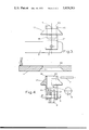
- FIG. 1 shows a section through a holding furnace with the portioning pump inserted therein and the valve means fixed into position.
- FIG. 2 shows the holding furnace including equipment viewed from above.
- FIG. 3 shows a magnified detail of the valve means in a lateral view.
- FIG. 4 shows a section through the bottom cover plate of the pouring container the valve means parts disassembled and partially shown in section.
- FIG. 1 is a section through the holding furnace and shows the pouring equipment inserted therein with the new valve means mounted in position.
- the valve means is designed with an upward open valve housing (FIG. 3 and 4), in which a valve bead, i.e., steel ball 6, has been provided.
- the valve ball 6 is maintained in position by a cotter 7 or the like.
- a lever 2 is rotatably connected with the valve housing 15, and its upper portion merges into an elongated shaft which extends above the melt and is fastened to a plate 8 by means of fastening means in the form of a wing nut 9 or the like, the plate 8 being rigidly connected with two suspension struts 19 which maintain the portioning container, designated by 5, in the proper depth in the melt.
- the lower portion of the lever 2 extends into a groove 21 in the lower portion of the valve housing, which groove forms the metal inlet to the portioning container.
- the lever 2 is pivoted to the valve housing 15 by means of a pin or bolt 3 which extends through coaxial holes through the lower part of the lever and the walls defining the groove 21. Good clearance is provided between the bolt 3 and such coaxial holes and a similar clearance is provided between the walls defining the groove 21 and the portion of lever 2 extending therein. In this way a simple and efficient articulated joint is achieved which is operative in all planes.
- the valve housing 15 is shown as being cylindrical and consists of an upper, open portion 16 having a sufficient clearance relative to a corresponding cylindrical portion of the peripheral wall defining the opening 22 in the bottom cover plate of the portioning container, which plate is designated by 4, to permit the valve housing 15 to be tilted relative to the vertical when inserted into the opening 22, i.e., relative to a normal to the bottom cover plate 4.
- the cylindrical valve housing further comprises an upwardly narrowing, conical flange 17 having an outer contact area designed to contact a conically shaped seating area 14 which is formed by the lower portion of the wall defining the opening 22 in the bottom cover plate 4.
- the contact area of the flange 17 and the seating area 14 are shown as being simple conical surfaces. However, it will be appreciated that one or both of these areas can very well be double-curved, for instance so as to form part of a sphere.
- the conicity or tapering angle of the flange 17, and of the seating area of the bottom plate, is of importance to ensure a self-centering insertion of the valve housing 15. If the angle with the horizontal plane is too small, one will not be able to make the valve housing slip into position, while, however, too great of an angle will not provide satisfactory sealing when operating with the clearance required to hit" when inserting the valve housing 15 into operating position. It has been found in practical tests that the best results are obtained when the angle of conicity of the flange 17 relative to the horizontal plane is from about 45 to about 60, corresponding to an angle relative to the axis of the valve housing of 3045. Even when the valve housing is 4 inserted obliquely into the opening 22 in the bottom cover plate 4, its conical contact surface will make it slip into position.
- the lever 2 can be lifted and lowered by means of a handle 11. This operation can readily be performed with one hand.
- lever 2 is moved into position and secured to the plate 8. The joint at the bolt 3 permits these movements.
- the plate 8 is rigidly connected with two struts 19 which maintain the portioning container submerged to a suitable depth in the melt.
- the entire portioning equipment including the lever 2 and the plate 8 can be moved back and forth along rack arms designated by 10.
- the wing nut 9 need only be tightened manually. Theoretically the upward pull power serves only to counteract the excess pressure on the valve means during portioning plus the weight of the lever 2 and the valve means. If the nut 9 is tightened too much, the lever 2 can be strained too much and permanently deformed, which of course is not desirable. Practical tests have shown that the valve provides satisfactory sealing when the wing nut 9 is tightened manually. It is important that the pull power is then acting along the longitudinal axis of the portioning container, so that the valve is pulled towards the center of the opening 22 to finally be centered therein.
- the lower portion of the valve housing 15 is constructed so that there will be ample passage for the metal to flow through the valve.
- the opening 22 in the bottom cover plate 4 is made wide enough to permit inspection as required on cleaning the interior of the portioning container 5.
- the lever 2, which is fastened to the plate 8, is mounted or located so as not to prevent the portioning tube, which has been designated by 13, from being moved as desired during portioning operations.
- the portioning tube 13 must be adjustable into various sloping angles and must be revolvable to either side.
- the portioning equipment is so constructed that the portioning tube 13 can be taken out of the melt without it being necessary to move any other part of the equipment.
- the lever 2 including the ball valve is first placed on the rim of the furnace to be preheated.
- the lever 2 can then be introduced either on the left-hand side or on the right-hand side of the gas supply tube, which has been designated by 12, and the valve means is inserted under the bottom cover plate 4.
- the valve means is self-centered as it slips upward along the contact area 14.
- the lever is then fastened to the plate 8. After about 5 minutes the lever will be hot and will have acquired maximum length extension.
- the wing nut 9 is then tightened manually and the pouring apparatus is ready for use.
- the ball valve After about 1 week of continual operation the ball valve must be renewed. The valve must be dismounted immediately after being removed from the melt. The cotter 7 is pulled out and the ball 6 is decanted through the opening 20 before getting stuck due to freezing of the metal residues in the valve. The bolt 3 is then pulled out and the ball valve can be replaced by a new valve. The oxidized (oxide coated) ball valve is cleaned by treatment in dilute nitric acid and can be reused.
- portion ing container 5 After a prolonged time of operation also the portion ing container 5 must be removed for cleaning and inspection.
- the valve body In the case of the prior art screwed-on valves, the valve body will prevent the metal from running out of the portioning container when the latter is lifted out of the melt. Often also the problem of oxide clogging of the inlet of the valve means arises, and it may be very difficult to drain the container.
- an apparatus for portioning liquid metal comprising a portioning container intended to be submerged into a reservoir of molten metal, means for supplying pressure gas to said container and a metal outlet therein to be connected with a mould, such as a die-casting machine, said container being provided with a demountable valve means positioned at a bottom portion thereof to permit liquid metal to flow into said container when gas pressure is relieved, the improvement wherein: said valve means comprises a valve housing having an upper portion which during operations extends through an opening in the bottom portion of said container with sufficient clearance to permit the valve housing to be tilted in relation to a vertical when 6 being inserted into said opening, said valve housing being provided with an outer, upward narrowing, generally conical flange having a contact area intended to contact a generally conically shaped seating area at said opening in the bottom portion of said container, said valve housing being pivoted to a lever.
- valve housing has a movable valve ball provided therein, is upwardly open, and is provided in its upper portion with a replaceable cotter to prevent said ball from moving out of said valve housing.
Landscapes
- Engineering & Computer Science (AREA)
- Mechanical Engineering (AREA)
- Casting Support Devices, Ladles, And Melt Control Thereby (AREA)
- Measuring Volume Flow (AREA)
- Valve Housings (AREA)
- Lift Valve (AREA)
Applications Claiming Priority (1)
| Application Number | Priority Date | Filing Date | Title |
|---|---|---|---|
| NO04065/73A NO130221B (de) | 1973-10-19 | 1973-10-19 |
Publications (1)
| Publication Number | Publication Date |
|---|---|
| US3929263A true US3929263A (en) | 1975-12-30 |
Family
ID=19880046
Family Applications (1)
| Application Number | Title | Priority Date | Filing Date |
|---|---|---|---|
| US516871A Expired - Lifetime US3929263A (en) | 1973-10-19 | 1974-10-21 | Apparatus for portioning liquid metal |
Country Status (8)
| Country | Link |
|---|---|
| US (1) | US3929263A (de) |
| JP (1) | JPS5223856B2 (de) |
| DE (1) | DE2449685C3 (de) |
| FR (1) | FR2248104B1 (de) |
| GB (1) | GB1473195A (de) |
| IT (1) | IT1021841B (de) |
| NO (1) | NO130221B (de) |
| SE (1) | SE7413034L (de) |
Cited By (1)
| Publication number | Priority date | Publication date | Assignee | Title |
|---|---|---|---|---|
| US5487496A (en) * | 1994-08-24 | 1996-01-30 | Gnb Battery Technologies, Inc. | Lead delivery system for casting straps in the manufacture and assembly of lead-acid batteries |
Families Citing this family (6)
| Publication number | Priority date | Publication date | Assignee | Title |
|---|---|---|---|---|
| DE2914810C2 (de) * | 1979-04-11 | 1983-05-05 | Institut problem lit'ja Akademii Nauk Ukrainskoj SSR, Kiev | Pneumatische Wiege-Eintauch-Dosiervorrichtung für schmelzflüssige Metalle |
| DE3012047C2 (de) * | 1980-03-28 | 1983-01-05 | Norsk Hydro Magnesiumgesellschaft mbH, 4300 Essen | Dosiereinrichtung zum Fördern von flüssigem Metall |
| DE3050183C2 (de) * | 1980-03-28 | 1983-09-15 | Norsk Hydro Magnesiumgesellschaft mbH, 4300 Essen | Dosiereinrichtung zum Fördern von flüssigem Metall |
| DE3023261C2 (de) * | 1980-06-21 | 1983-01-13 | Norsk Hydro Magnesiumgesellschaft mbH, 4300 Essen | Mundstück für das Ende einer Förderleitung einer Dosiereinrichtung zum Fördern von flüssigem Metall |
| DE3023262C2 (de) * | 1980-06-21 | 1982-12-23 | Norsk Hydro Magnesiumgesellschaft mbH, 4300 Essen | Mundstück zu Anschluß einer Förderleitung einer Dosiereinrichtung zum Fördern von flüssigem Metall an den Anguß einer Gießform |
| DE4322264C1 (de) * | 1993-07-05 | 1994-09-29 | Werner Kluge | Füllvorrichtung zur Flüssigmetallbeschickung von Aluminium |
Citations (1)
| Publication number | Priority date | Publication date | Assignee | Title |
|---|---|---|---|---|
| US2609575A (en) * | 1949-05-12 | 1952-09-09 | Louis H Morin | Apparatus for pressure injecting casting material by diaphragm pumps |
-
1973
- 1973-10-19 NO NO04065/73A patent/NO130221B/no unknown
-
1974
- 1974-10-16 SE SE7413034A patent/SE7413034L/xx unknown
- 1974-10-17 IT IT53594/74A patent/IT1021841B/it active
- 1974-10-18 DE DE2449685A patent/DE2449685C3/de not_active Expired
- 1974-10-18 JP JP49119465A patent/JPS5223856B2/ja not_active Expired
- 1974-10-18 FR FR7435119A patent/FR2248104B1/fr not_active Expired
- 1974-10-21 GB GB4545674A patent/GB1473195A/en not_active Expired
- 1974-10-21 US US516871A patent/US3929263A/en not_active Expired - Lifetime
Patent Citations (1)
| Publication number | Priority date | Publication date | Assignee | Title |
|---|---|---|---|---|
| US2609575A (en) * | 1949-05-12 | 1952-09-09 | Louis H Morin | Apparatus for pressure injecting casting material by diaphragm pumps |
Cited By (1)
| Publication number | Priority date | Publication date | Assignee | Title |
|---|---|---|---|---|
| US5487496A (en) * | 1994-08-24 | 1996-01-30 | Gnb Battery Technologies, Inc. | Lead delivery system for casting straps in the manufacture and assembly of lead-acid batteries |
Also Published As
| Publication number | Publication date |
|---|---|
| SE7413034L (de) | 1975-04-21 |
| JPS5078527A (de) | 1975-06-26 |
| GB1473195A (en) | 1977-05-11 |
| DE2449685B2 (de) | 1977-10-13 |
| JPS5223856B2 (de) | 1977-06-27 |
| DE2449685A1 (de) | 1975-04-24 |
| FR2248104B1 (de) | 1977-03-25 |
| DE2449685C3 (de) | 1978-06-15 |
| FR2248104A1 (de) | 1975-05-16 |
| IT1021841B (it) | 1978-02-20 |
| NO130221B (de) | 1974-07-29 |
Similar Documents
| Publication | Publication Date | Title |
|---|---|---|
| US3929263A (en) | Apparatus for portioning liquid metal | |
| US4468172A (en) | Jet pump plug | |
| US2625720A (en) | Pump for type casting | |
| WO1982003875A1 (en) | Immersion and vaporization chamber | |
| JPH0667549B2 (ja) | 容器の出口バルブ | |
| DE20010305U1 (de) | Einrichtung zum Versetzen von Flüssigkeiten mit Kohlensäure | |
| US2216921A (en) | Method and apparatus for introducing solids into a pressure system | |
| DE69837365T2 (de) | Hochintensitätsmischer | |
| US2073925A (en) | Portable agitator | |
| JP3317585B2 (ja) | 非鉄金属溶湯の定量注湯装置 | |
| US2944626A (en) | Degassing fluids | |
| DE2130933A1 (de) | Vorrichtung und Verfahren zum kontinuierlichen Giessen von Metall | |
| US964126A (en) | Etching-machine. | |
| US3103718A (en) | Apparatus for producing seamless pipe | |
| AU4305400A (en) | Improved method and device for degasing and separation of inclusions in a liquidmetal bath by injection of gas bubbles | |
| JPS5913010A (ja) | 冶金容器の排出方法と装置 | |
| EP0281508B1 (de) | Vorrichtung für die Entgasung von geschmolzenem Metall | |
| DE535563C (de) | Verfahren und Vorrichtung zur Herstellung von Schleudergusshohlkoerpern | |
| DE2950676C2 (de) | Vorrichtung zum gleichmäßigen Mischen und Spritzen von mit festen Stoffen angereicherten Flüssigkeiten | |
| DE1508560C (de) | Verfahren und Vorrichtung zum Entlee ren von Schmelz oder Warmhalteofen | |
| DE605637C (de) | Befestigung von Aufnehmern fuer Rohr- und Strangpressen | |
| DE19963216A1 (de) | Verfahren und Vorrichtung zum Gießen von Rohlingen aus Leichtmetall | |
| DE703387C (de) | Vorrichtung zum gleichzeitigen Ausscheiden von Hopfenharz und zum Mischen des Bieres beim Schlauchen | |
| SU707691A1 (ru) | Установка дл торкретировани металлургических емкостей | |
| RU17537U1 (ru) | Устройство для нанесения покрытия |