US2077458A - Tie case - Google Patents
Tie case Download PDFInfo
- Publication number
- US2077458A US2077458A US51306A US5130635A US2077458A US 2077458 A US2077458 A US 2077458A US 51306 A US51306 A US 51306A US 5130635 A US5130635 A US 5130635A US 2077458 A US2077458 A US 2077458A
- Authority
- US
- United States
- Prior art keywords
- tie
- case
- sheet
- ties
- sheets
- Prior art date
- Legal status (The legal status is an assumption and is not a legal conclusion. Google has not performed a legal analysis and makes no representation as to the accuracy of the status listed.)
- Expired - Lifetime
Links
Images
Classifications
-
- B—PERFORMING OPERATIONS; TRANSPORTING
- B65—CONVEYING; PACKING; STORING; HANDLING THIN OR FILAMENTARY MATERIAL
- B65D—CONTAINERS FOR STORAGE OR TRANSPORT OF ARTICLES OR MATERIALS, e.g. BAGS, BARRELS, BOTTLES, BOXES, CANS, CARTONS, CRATES, DRUMS, JARS, TANKS, HOPPERS, FORWARDING CONTAINERS; ACCESSORIES, CLOSURES, OR FITTINGS THEREFOR; PACKAGING ELEMENTS; PACKAGES
- B65D85/00—Containers, packaging elements or packages, specially adapted for particular articles or materials
- B65D85/18—Containers, packaging elements or packages, specially adapted for particular articles or materials for wearing apparel, headwear or footwear
Definitions
- the principal object of my invention is to provide a tie case for holding a plurality of ties that successfully preserves the ties placed in it against wrinkling.
- a further object of this invention is to provide a tie case that permits the ties to be easily and quickly removed from it or properly placed in it.
- a still further object of this invention is to provide a tie case that requires little room in the suit case, grip, bureau drawer or like.
- My invention consists in the construction, ar-
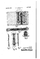
- Fig. 1 is a top plan view.o1' my case-in open condition showing ties held therein.l
- Fig. 2 is a bottom view of my case and more fully illustrates its construction.
- Fig. 3 is a side view of one of the tie holding sheets removed from the case housing.
- Fig. 4 is a frontplan view of a modiiied form of construction for holding a tie on a tie holdingA sheet.
- Fig. 5 is a longitudinal-sectional view of the construction shown in Fig. 4 and is taken on line 5-5 oi' that gure.
- Fig. 6 is a sectional view of the construction employedfor securing the tie holding sheets in the case proper.
- I have used the numeral I0 to designate the tie case housing consisting chiey of a back cover and a front cover capable of folding over the back cover, as shown in Fig. 2.
- the back cover portion may have a flap portion II on its free marginal edge capable of being folded over the free marginal side edge portion of 'the front cover.
- This flap II and front cover may be detachably secured together by glove snap fasteners I 2.
- I have used the numeral I3 to designate the detachable tie holding sheets.
- These sheets I3 andthe case housing may be made of any suitable sheet material such as leather, fabricoid, or like.'4
- the sheets I3 may be secured by any suitable means to the inside of the Acase housing.
- I show these sheets detachably secured at their side marginal ledge portions to the center fold portion of the 'case,housing. I accomplish this by providing a short-double fold designed by the numerals I4 and I5, respectively, and located between the back and front cover as shown in Fig. 2 and Fig. 6. This provides a receiving channel between the two folds I4 and I5 for the reception of the edge portions of the sheets I3.
- the sheets I3 are detachably held between these two short folds by removable bolts I6 that pass through the two folds and the sheets I3. y
- tie engaging loops I 8 are each in the form of a bar secured at each of its end portions to the sheet I3 by suitable means such as sewing, rivets, etc. By being secured at each end, these elements I8 provide a loop around which the tie to be held is looped as shown in Fig. 3.
- tie engaging loops are located near the top or bottom of the sheet to which they are secured and the ties being supported thereon extend over the face of the sheet, as shown in Fig. 1.
- the tie engaging clasps I 9 extend over the two end portions of the ties.
- 'I'hese engaging clasps are in the form of bars, each secured at one of its ends by a rivet, sewing, or like, to the sheetV I3 and its other end detachably secured to the sheet.
- Various methods may be used to detachably secure the free ends of these elements I9 to its sheet I3.
- I show glove snap fasteners 20.
- a tie to be held is looped around one of ends of substantially equal length from the member I8. 'I'he tie is then straightened out on the sheet I3 and the tie holding clasp I9 placed over it. Lastly, the free end of the member I9 is snapped on or otherwise attachably secured to the sheet. To remove l to detach the free end of the member I9 from the sheet and pull the tie from around the loop member I9.
- Themembers I8 and I9 may be of any suitable pliable material such as that used for the sheets I3 or case III. The number of ties placed on a sheet will depend on the si'zc of the sheet. From one to many of these sheets I3 may be detachably placedin a case housing I0.
- FIGs. 4 and 5 show a modified form of constructing the tie holding loops and tie holding clasps.
- I have used the numeral I3' to designate the tie holding loop and the numeral I9" to designate the tie holding clasp.
- 'I'he loop I8' isformed by'cutting two spaced apart parallel slits 2I and 22 in the sheet I3.
- the tie holding clasp I9' is secured at one end by any suitable means such as a rivet, sewing, or like.
- the loop I8' serves the same purpose as the tie holding loop I8 shown in Fig. 1.
- the tieholding clasp I9 is similar to the tie holding clasp I9, but instead of being secured at its free end to the sheet I3 by a glove snap fastener, its free end a tie it is merely necessary portion is inserted into and through the slot opening 23, as shown in Fig. 4.
- a ilexible sheet member In a tie case, a ilexible sheet member, an elongated exible loop member having its two ends rigidly secured on the upper portion of said flexible sheet member extending transversally of the longitudinal length of the said iiexible sheet member and ⁇ designed to have the center portion of a necktie looped around it with the major portion ofthe outer length portion of the tie resting on the major portion of the under length portion of the tie and both under and outer portions of the tie extendingl downwardly over the uuper surface of said exible sheet member, a exible bar member rigidly secured at one of its ends to the lower portion of said flexible sheet member ⁇ and designed to extend transversally across the lower end portions Vof said tie, and a means for detachably securing the other end of said bar member to said ilexible sheet member.
Landscapes
- Engineering & Computer Science (AREA)
- Mechanical Engineering (AREA)
- Holders For Apparel And Elements Relating To Apparel (AREA)
Description
April 2o,` 1937.
G. E. CHESNUT,` JR
TIE CASE.
Filed Nov. 25, 1935 INVENTOR. GuyE .Chesnut'jn BY vi4 y are the most diiilcult to keep in Patented Apr. 20, 1937 UNITED STATES PATENT OFFICE 1 Claim.
The principal object of my invention is to provide a tie case for holding a plurality of ties that successfully preserves the ties placed in it against wrinkling. I
A further object of this invention is to provide a tie case that permits the ties to be easily and quickly removed from it or properly placed in it.
A still further object of this invention is to provide a tie case that requires little room in the suit case, grip, bureau drawer or like.
A still further object of my invention is to provide a tie holding case that permits the ready inspection or selection of the ties in the case. l5' A still further object of my invention is to provide a tie case that is rened in appearance, economical in manufacture, and durable in use.`
These and other objects will be apparent to those skilled in the art.
My invention consists in the construction, ar-
rangement, and combination of the various parts of the device, whereby the objects contemplated are attained as hereinafter more fully set forth, pointed out in my claims and4 illustrated in the accompanying drawing, in which:
Fig. 1 is a top plan view.o1' my case-in open condition showing ties held therein.l
Fig. 2 is a bottom view of my case and more fully illustrates its construction. l
Fig. 3 is a side view of one of the tie holding sheets removed from the case housing.
Fig. 4 is a frontplan view of a modiiied form of construction for holding a tie on a tie holdingA sheet.
Fig. 5 is a longitudinal-sectional view of the construction shown in Fig. 4 and is taken on line 5-5 oi' that gure. f Fig. 6 is a sectional view of the construction employedfor securing the tie holding sheets in the case proper.
0f all wearing apparel for men, perhaps ties suitable condition for wear. 'I'he reason for this is that more than one tie is necessary in ones wardrobe and the ties not being worn are usually placed in loose, drawer, or like. This is especially true when traveling. Obviously, under such conditions not only do the ties become badly soiled and wrinkled, but are dimcult to und-inasmuch as they are usually all mixed upwith other effects in the traveling bag, grip, drawer, or like. I have .overcome such objections by providing a tie case that detachably holds and displays the ties in ilat condisarranged order inthe grip, Suit case,
dition as well as protecting them from dust, dirt, and other foreign' matter.
Referring to the drawing, I have used the numeral I0 to designate the tie case housing consisting chiey of a back cover and a front cover capable of folding over the back cover, as shown in Fig. 2. The back cover portion may have a flap portion II on its free marginal edge capable of being folded over the free marginal side edge portion of 'the front cover. This flap II and front cover may be detachably secured together by glove snap fasteners I 2. I have used the numeral I3 to designate the detachable tie holding sheets. These sheets I3 andthe case housing may be made of any suitable sheet material such as leather, fabricoid, or like.'4 The sheets I3 may be secured by any suitable means to the inside of the Acase housing. In the drawing, I show these sheets detachably secured at their side marginal ledge portions to the center fold portion of the 'case,housing. I accomplish this by providing a short-double fold designed by the numerals I4 and I5, respectively, and located between the back and front cover as shown in Fig. 2 and Fig. 6. This provides a receiving channel between the two folds I4 and I5 for the reception of the edge portions of the sheets I3. The sheets I3 are detachably held between these two short folds by removable bolts I6 that pass through the two folds and the sheets I3. y
On the sheets I3 I mount my ties to beheld and which I have designated by the numeral I1. Each tie is held on its sheet I3 by a tie engaging loop I8 and a tie engaging clasp I9. These tie engaging loops I 8 are each in the form of a bar secured at each of its end portions to the sheet I3 by suitable means such as sewing, rivets, etc. By being secured at each end, these elements I8 provide a loop around which the tie to be held is looped as shown in Fig. 3.
Obviously, these tie engaging loops are located near the top or bottom of the sheet to which they are secured and the ties being supported thereon extend over the face of the sheet, as shown in Fig. 1. The tie engaging clasps I 9 extend over the two end portions of the ties. 'I'hese engaging clasps are in the form of bars, each secured at one of its ends by a rivet, sewing, or like, to the sheetV I3 and its other end detachably secured to the sheet. Various methods may be used to detachably secure the free ends of these elements I9 to its sheet I3. In'Figs. l, 2, and 3, I show glove snap fasteners 20.
The practical operation of my device is as fol'- lows: A tie to be held is looped around one of ends of substantially equal length from the member I8. 'I'he tie is then straightened out on the sheet I3 and the tie holding clasp I9 placed over it. Lastly, the free end of the member I9 is snapped on or otherwise attachably secured to the sheet. To remove l to detach the free end of the member I9 from the sheet and pull the tie from around the loop member I9. Themembers I8 and I9 may be of any suitable pliable material such as that used for the sheets I3 or case III. The number of ties placed on a sheet will depend on the si'zc of the sheet. From one to many of these sheets I3 may be detachably placedin a case housing I0.
In Figs. 4 and 5, I show a modified form of constructing the tie holding loops and tie holding clasps. In these Figures I have used the numeral I3' to designate the tie holding loop and the numeral I9" to designate the tie holding clasp. 'I'he loop I8' isformed by'cutting two spaced apart parallel slits 2I and 22 in the sheet I3. The tie holding clasp I9' is secured at one end by any suitable means such as a rivet, sewing, or like.
The loop I8' serves the same purpose as the tie holding loop I8 shown in Fig. 1. The tieholding clasp I9 is similar to the tie holding clasp I9, but instead of being secured at its free end to the sheet I3 by a glove snap fastener, its free end a tie it is merely necessary portion is inserted into and through the slot opening 23, as shown in Fig. 4.
Some changes may be made in the construction and arrangement of my improved tie case without departing from the real spirit and purpose of my invention, and it is my intention to cover by my claim any modiiled forms o1' structure or use of mechanical equivalents which'may be reasonabiy included within its scope.
I claim:
In a tie case, a ilexible sheet member, an elongated exible loop member having its two ends rigidly secured on the upper portion of said flexible sheet member extending transversally of the longitudinal length of the said iiexible sheet member and `designed to have the center portion of a necktie looped around it with the major portion ofthe outer length portion of the tie resting on the major portion of the under length portion of the tie and both under and outer portions of the tie extendingl downwardly over the uuper surface of said exible sheet member, a exible bar member rigidly secured at one of its ends to the lower portion of said flexible sheet member `and designed to extend transversally across the lower end portions Vof said tie, and a means for detachably securing the other end of said bar member to said ilexible sheet member. f
GUY E. CHESNUT, Jn.
Priority Applications (1)
| Application Number | Priority Date | Filing Date | Title |
|---|---|---|---|
| US51306A US2077458A (en) | 1935-11-23 | 1935-11-23 | Tie case |
Applications Claiming Priority (1)
| Application Number | Priority Date | Filing Date | Title |
|---|---|---|---|
| US51306A US2077458A (en) | 1935-11-23 | 1935-11-23 | Tie case |
Publications (1)
| Publication Number | Publication Date |
|---|---|
| US2077458A true US2077458A (en) | 1937-04-20 |
Family
ID=21970468
Family Applications (1)
| Application Number | Title | Priority Date | Filing Date |
|---|---|---|---|
| US51306A Expired - Lifetime US2077458A (en) | 1935-11-23 | 1935-11-23 | Tie case |
Country Status (1)
| Country | Link |
|---|---|
| US (1) | US2077458A (en) |
Cited By (5)
| Publication number | Priority date | Publication date | Assignee | Title |
|---|---|---|---|---|
| US2488973A (en) * | 1947-04-22 | 1949-11-22 | Phyllis W Hall | Cravat carrier and conditioner |
| US2659643A (en) * | 1950-08-30 | 1953-11-17 | Eugene G Friesz | Tie rack |
| FR2642047A1 (en) * | 1989-01-26 | 1990-07-27 | Sepaic | Device for retaining thin articles on a standard support |
| US6102216A (en) * | 1999-03-11 | 2000-08-15 | Frank; Monty S | Attire organizer |
| US20120048816A1 (en) * | 2010-08-30 | 2012-03-01 | Shatikwa Brown | Shoe Hanging Rack System |
-
1935
- 1935-11-23 US US51306A patent/US2077458A/en not_active Expired - Lifetime
Cited By (6)
| Publication number | Priority date | Publication date | Assignee | Title |
|---|---|---|---|---|
| US2488973A (en) * | 1947-04-22 | 1949-11-22 | Phyllis W Hall | Cravat carrier and conditioner |
| US2659643A (en) * | 1950-08-30 | 1953-11-17 | Eugene G Friesz | Tie rack |
| FR2642047A1 (en) * | 1989-01-26 | 1990-07-27 | Sepaic | Device for retaining thin articles on a standard support |
| US6102216A (en) * | 1999-03-11 | 2000-08-15 | Frank; Monty S | Attire organizer |
| US20120048816A1 (en) * | 2010-08-30 | 2012-03-01 | Shatikwa Brown | Shoe Hanging Rack System |
| US8657124B2 (en) * | 2010-08-30 | 2014-02-25 | Shatikwa Brown | Shoe hanging rack system |
Similar Documents
| Publication | Publication Date | Title |
|---|---|---|
| US2754532A (en) | Sportsman's towel | |
| US2474495A (en) | Belt purse | |
| US2717390A (en) | One piece folded garment | |
| US1411562A (en) | Apron | |
| US2753569A (en) | Shoulder strap for women's undergarments | |
| US2868371A (en) | Display package | |
| US2077458A (en) | Tie case | |
| US1877697A (en) | Detachable bath robe belt | |
| US3184759A (en) | Handkerchief holder | |
| US1388073A (en) | Cigarette-case | |
| US2671219A (en) | Garment | |
| US2551184A (en) | Handkerchife holder | |
| US1895074A (en) | Article holster | |
| US2076925A (en) | Adjustable waist band or belt | |
| US1604090A (en) | Necktie holder | |
| US1524457A (en) | Apron | |
| US2275682A (en) | Necktie and necktie fastener | |
| US1772298A (en) | Combination garment | |
| US1897090A (en) | Shirt retaining device | |
| US1676291A (en) | Tie | |
| US1896681A (en) | Retaining device | |
| US2123436A (en) | Hair cutting cloth | |
| US2061293A (en) | Lady's handbag | |
| US2823384A (en) | Shoulder strap clasp | |
| US2315161A (en) | Detachable belt loop |