US20180098789A1 - Devices and methods for providing surgical access - Google Patents
Devices and methods for providing surgical access Download PDFInfo
- Publication number
- US20180098789A1 US20180098789A1 US15/786,858 US201715786858A US2018098789A1 US 20180098789 A1 US20180098789 A1 US 20180098789A1 US 201715786858 A US201715786858 A US 201715786858A US 2018098789 A1 US2018098789 A1 US 2018098789A1
- Authority
- US
- United States
- Prior art keywords
- tube
- access device
- inner tube
- outer tube
- length
- Prior art date
- Legal status (The legal status is an assumption and is not a legal conclusion. Google has not performed a legal analysis and makes no representation as to the accuracy of the status listed.)
- Granted
Links
Images


Classifications
-
- A—HUMAN NECESSITIES
- A61—MEDICAL OR VETERINARY SCIENCE; HYGIENE
- A61B—DIAGNOSIS; SURGERY; IDENTIFICATION
- A61B1/00—Instruments for performing medical examinations of the interior of cavities or tubes of the body by visual or photographical inspection, e.g. endoscopes; Illuminating arrangements therefor
- A61B1/00002—Operational features of endoscopes
- A61B1/00043—Operational features of endoscopes provided with output arrangements
- A61B1/00045—Display arrangement
-
- A—HUMAN NECESSITIES
- A61—MEDICAL OR VETERINARY SCIENCE; HYGIENE
- A61B—DIAGNOSIS; SURGERY; IDENTIFICATION
- A61B1/00—Instruments for performing medical examinations of the interior of cavities or tubes of the body by visual or photographical inspection, e.g. endoscopes; Illuminating arrangements therefor
- A61B1/00064—Constructional details of the endoscope body
- A61B1/00071—Insertion part of the endoscope body
- A61B1/0008—Insertion part of the endoscope body characterised by distal tip features
- A61B1/00089—Hoods
-
- A—HUMAN NECESSITIES
- A61—MEDICAL OR VETERINARY SCIENCE; HYGIENE
- A61B—DIAGNOSIS; SURGERY; IDENTIFICATION
- A61B1/00—Instruments for performing medical examinations of the interior of cavities or tubes of the body by visual or photographical inspection, e.g. endoscopes; Illuminating arrangements therefor
- A61B1/00064—Constructional details of the endoscope body
- A61B1/00071—Insertion part of the endoscope body
- A61B1/0008—Insertion part of the endoscope body characterised by distal tip features
- A61B1/00091—Nozzles
-
- A—HUMAN NECESSITIES
- A61—MEDICAL OR VETERINARY SCIENCE; HYGIENE
- A61B—DIAGNOSIS; SURGERY; IDENTIFICATION
- A61B1/00—Instruments for performing medical examinations of the interior of cavities or tubes of the body by visual or photographical inspection, e.g. endoscopes; Illuminating arrangements therefor
- A61B1/00064—Constructional details of the endoscope body
- A61B1/00071—Insertion part of the endoscope body
- A61B1/0008—Insertion part of the endoscope body characterised by distal tip features
- A61B1/00094—Suction openings
-
- A—HUMAN NECESSITIES
- A61—MEDICAL OR VETERINARY SCIENCE; HYGIENE
- A61B—DIAGNOSIS; SURGERY; IDENTIFICATION
- A61B1/00—Instruments for performing medical examinations of the interior of cavities or tubes of the body by visual or photographical inspection, e.g. endoscopes; Illuminating arrangements therefor
- A61B1/00064—Constructional details of the endoscope body
- A61B1/00071—Insertion part of the endoscope body
- A61B1/0008—Insertion part of the endoscope body characterised by distal tip features
- A61B1/00096—Optical elements
-
- A—HUMAN NECESSITIES
- A61—MEDICAL OR VETERINARY SCIENCE; HYGIENE
- A61B—DIAGNOSIS; SURGERY; IDENTIFICATION
- A61B1/00—Instruments for performing medical examinations of the interior of cavities or tubes of the body by visual or photographical inspection, e.g. endoscopes; Illuminating arrangements therefor
- A61B1/00064—Constructional details of the endoscope body
- A61B1/00103—Constructional details of the endoscope body designed for single use
-
- A—HUMAN NECESSITIES
- A61—MEDICAL OR VETERINARY SCIENCE; HYGIENE
- A61B—DIAGNOSIS; SURGERY; IDENTIFICATION
- A61B1/00—Instruments for performing medical examinations of the interior of cavities or tubes of the body by visual or photographical inspection, e.g. endoscopes; Illuminating arrangements therefor
- A61B1/00112—Connection or coupling means
- A61B1/00121—Connectors, fasteners and adapters, e.g. on the endoscope handle
- A61B1/00128—Connectors, fasteners and adapters, e.g. on the endoscope handle mechanical, e.g. for tubes or pipes
-
- A—HUMAN NECESSITIES
- A61—MEDICAL OR VETERINARY SCIENCE; HYGIENE
- A61B—DIAGNOSIS; SURGERY; IDENTIFICATION
- A61B1/00—Instruments for performing medical examinations of the interior of cavities or tubes of the body by visual or photographical inspection, e.g. endoscopes; Illuminating arrangements therefor
- A61B1/00131—Accessories for endoscopes
- A61B1/00133—Drive units for endoscopic tools inserted through or with the endoscope
-
- A—HUMAN NECESSITIES
- A61—MEDICAL OR VETERINARY SCIENCE; HYGIENE
- A61B—DIAGNOSIS; SURGERY; IDENTIFICATION
- A61B1/00—Instruments for performing medical examinations of the interior of cavities or tubes of the body by visual or photographical inspection, e.g. endoscopes; Illuminating arrangements therefor
- A61B1/00131—Accessories for endoscopes
- A61B1/00135—Oversleeves mounted on the endoscope prior to insertion
-
- A—HUMAN NECESSITIES
- A61—MEDICAL OR VETERINARY SCIENCE; HYGIENE
- A61B—DIAGNOSIS; SURGERY; IDENTIFICATION
- A61B1/00—Instruments for performing medical examinations of the interior of cavities or tubes of the body by visual or photographical inspection, e.g. endoscopes; Illuminating arrangements therefor
- A61B1/00147—Holding or positioning arrangements
- A61B1/00154—Holding or positioning arrangements using guiding arrangements for insertion
-
- A—HUMAN NECESSITIES
- A61—MEDICAL OR VETERINARY SCIENCE; HYGIENE
- A61B—DIAGNOSIS; SURGERY; IDENTIFICATION
- A61B1/00—Instruments for performing medical examinations of the interior of cavities or tubes of the body by visual or photographical inspection, e.g. endoscopes; Illuminating arrangements therefor
- A61B1/012—Instruments for performing medical examinations of the interior of cavities or tubes of the body by visual or photographical inspection, e.g. endoscopes; Illuminating arrangements therefor characterised by internal passages or accessories therefor
- A61B1/018—Instruments for performing medical examinations of the interior of cavities or tubes of the body by visual or photographical inspection, e.g. endoscopes; Illuminating arrangements therefor characterised by internal passages or accessories therefor for receiving instruments
-
- A—HUMAN NECESSITIES
- A61—MEDICAL OR VETERINARY SCIENCE; HYGIENE
- A61B—DIAGNOSIS; SURGERY; IDENTIFICATION
- A61B1/00—Instruments for performing medical examinations of the interior of cavities or tubes of the body by visual or photographical inspection, e.g. endoscopes; Illuminating arrangements therefor
- A61B1/04—Instruments for performing medical examinations of the interior of cavities or tubes of the body by visual or photographical inspection, e.g. endoscopes; Illuminating arrangements therefor combined with photographic or television appliances
- A61B1/05—Instruments for performing medical examinations of the interior of cavities or tubes of the body by visual or photographical inspection, e.g. endoscopes; Illuminating arrangements therefor combined with photographic or television appliances characterised by the image sensor, e.g. camera, being in the distal end portion
- A61B1/051—Details of CCD assembly
-
- A—HUMAN NECESSITIES
- A61—MEDICAL OR VETERINARY SCIENCE; HYGIENE
- A61B—DIAGNOSIS; SURGERY; IDENTIFICATION
- A61B1/00—Instruments for performing medical examinations of the interior of cavities or tubes of the body by visual or photographical inspection, e.g. endoscopes; Illuminating arrangements therefor
- A61B1/04—Instruments for performing medical examinations of the interior of cavities or tubes of the body by visual or photographical inspection, e.g. endoscopes; Illuminating arrangements therefor combined with photographic or television appliances
- A61B1/055—Instruments for performing medical examinations of the interior of cavities or tubes of the body by visual or photographical inspection, e.g. endoscopes; Illuminating arrangements therefor combined with photographic or television appliances having rod-lens arrangements
-
- A—HUMAN NECESSITIES
- A61—MEDICAL OR VETERINARY SCIENCE; HYGIENE
- A61B—DIAGNOSIS; SURGERY; IDENTIFICATION
- A61B1/00—Instruments for performing medical examinations of the interior of cavities or tubes of the body by visual or photographical inspection, e.g. endoscopes; Illuminating arrangements therefor
- A61B1/06—Instruments for performing medical examinations of the interior of cavities or tubes of the body by visual or photographical inspection, e.g. endoscopes; Illuminating arrangements therefor with illuminating arrangements
- A61B1/07—Instruments for performing medical examinations of the interior of cavities or tubes of the body by visual or photographical inspection, e.g. endoscopes; Illuminating arrangements therefor with illuminating arrangements using light-conductive means, e.g. optical fibres
-
- A—HUMAN NECESSITIES
- A61—MEDICAL OR VETERINARY SCIENCE; HYGIENE
- A61B—DIAGNOSIS; SURGERY; IDENTIFICATION
- A61B1/00—Instruments for performing medical examinations of the interior of cavities or tubes of the body by visual or photographical inspection, e.g. endoscopes; Illuminating arrangements therefor
- A61B1/12—Instruments for performing medical examinations of the interior of cavities or tubes of the body by visual or photographical inspection, e.g. endoscopes; Illuminating arrangements therefor with cooling or rinsing arrangements
- A61B1/126—Instruments for performing medical examinations of the interior of cavities or tubes of the body by visual or photographical inspection, e.g. endoscopes; Illuminating arrangements therefor with cooling or rinsing arrangements provided with means for cleaning in-use
-
- A—HUMAN NECESSITIES
- A61—MEDICAL OR VETERINARY SCIENCE; HYGIENE
- A61B—DIAGNOSIS; SURGERY; IDENTIFICATION
- A61B1/00—Instruments for performing medical examinations of the interior of cavities or tubes of the body by visual or photographical inspection, e.g. endoscopes; Illuminating arrangements therefor
- A61B1/233—Instruments for performing medical examinations of the interior of cavities or tubes of the body by visual or photographical inspection, e.g. endoscopes; Illuminating arrangements therefor for the nose, i.e. nasoscopes, e.g. testing of patency of Eustachian tubes
-
- A—HUMAN NECESSITIES
- A61—MEDICAL OR VETERINARY SCIENCE; HYGIENE
- A61B—DIAGNOSIS; SURGERY; IDENTIFICATION
- A61B1/00—Instruments for performing medical examinations of the interior of cavities or tubes of the body by visual or photographical inspection, e.g. endoscopes; Illuminating arrangements therefor
- A61B1/267—Instruments for performing medical examinations of the interior of cavities or tubes of the body by visual or photographical inspection, e.g. endoscopes; Illuminating arrangements therefor for the respiratory tract, e.g. laryngoscopes, bronchoscopes
- A61B1/2676—Bronchoscopes
-
- A—HUMAN NECESSITIES
- A61—MEDICAL OR VETERINARY SCIENCE; HYGIENE
- A61B—DIAGNOSIS; SURGERY; IDENTIFICATION
- A61B1/00—Instruments for performing medical examinations of the interior of cavities or tubes of the body by visual or photographical inspection, e.g. endoscopes; Illuminating arrangements therefor
- A61B1/313—Instruments for performing medical examinations of the interior of cavities or tubes of the body by visual or photographical inspection, e.g. endoscopes; Illuminating arrangements therefor for introducing through surgical openings, e.g. laparoscopes
- A61B1/3132—Instruments for performing medical examinations of the interior of cavities or tubes of the body by visual or photographical inspection, e.g. endoscopes; Illuminating arrangements therefor for introducing through surgical openings, e.g. laparoscopes for laparoscopy
-
- A—HUMAN NECESSITIES
- A61—MEDICAL OR VETERINARY SCIENCE; HYGIENE
- A61B—DIAGNOSIS; SURGERY; IDENTIFICATION
- A61B1/00—Instruments for performing medical examinations of the interior of cavities or tubes of the body by visual or photographical inspection, e.g. endoscopes; Illuminating arrangements therefor
- A61B1/313—Instruments for performing medical examinations of the interior of cavities or tubes of the body by visual or photographical inspection, e.g. endoscopes; Illuminating arrangements therefor for introducing through surgical openings, e.g. laparoscopes
- A61B1/3135—Instruments for performing medical examinations of the interior of cavities or tubes of the body by visual or photographical inspection, e.g. endoscopes; Illuminating arrangements therefor for introducing through surgical openings, e.g. laparoscopes for examination of the epidural or the spinal space
-
- A—HUMAN NECESSITIES
- A61—MEDICAL OR VETERINARY SCIENCE; HYGIENE
- A61B—DIAGNOSIS; SURGERY; IDENTIFICATION
- A61B1/00—Instruments for performing medical examinations of the interior of cavities or tubes of the body by visual or photographical inspection, e.g. endoscopes; Illuminating arrangements therefor
- A61B1/313—Instruments for performing medical examinations of the interior of cavities or tubes of the body by visual or photographical inspection, e.g. endoscopes; Illuminating arrangements therefor for introducing through surgical openings, e.g. laparoscopes
- A61B1/317—Instruments for performing medical examinations of the interior of cavities or tubes of the body by visual or photographical inspection, e.g. endoscopes; Illuminating arrangements therefor for introducing through surgical openings, e.g. laparoscopes for bones or joints, e.g. osteoscopes, arthroscopes
-
- A—HUMAN NECESSITIES
- A61—MEDICAL OR VETERINARY SCIENCE; HYGIENE
- A61B—DIAGNOSIS; SURGERY; IDENTIFICATION
- A61B1/00—Instruments for performing medical examinations of the interior of cavities or tubes of the body by visual or photographical inspection, e.g. endoscopes; Illuminating arrangements therefor
- A61B1/32—Devices for opening or enlarging the visual field, e.g. of a tube of the body
-
- A—HUMAN NECESSITIES
- A61—MEDICAL OR VETERINARY SCIENCE; HYGIENE
- A61B—DIAGNOSIS; SURGERY; IDENTIFICATION
- A61B17/00—Surgical instruments, devices or methods
- A61B17/00234—Surgical instruments, devices or methods for minimally invasive surgery
-
- A—HUMAN NECESSITIES
- A61—MEDICAL OR VETERINARY SCIENCE; HYGIENE
- A61B—DIAGNOSIS; SURGERY; IDENTIFICATION
- A61B17/00—Surgical instruments, devices or methods
- A61B17/02—Surgical instruments, devices or methods for holding wounds open, e.g. retractors; Tractors
- A61B17/025—Joint distractors
-
- A—HUMAN NECESSITIES
- A61—MEDICAL OR VETERINARY SCIENCE; HYGIENE
- A61B—DIAGNOSIS; SURGERY; IDENTIFICATION
- A61B17/00—Surgical instruments, devices or methods
- A61B17/02—Surgical instruments, devices or methods for holding wounds open, e.g. retractors; Tractors
- A61B17/0293—Surgical instruments, devices or methods for holding wounds open, e.g. retractors; Tractors with ring member to support retractor elements
-
- A—HUMAN NECESSITIES
- A61—MEDICAL OR VETERINARY SCIENCE; HYGIENE
- A61B—DIAGNOSIS; SURGERY; IDENTIFICATION
- A61B17/00—Surgical instruments, devices or methods
- A61B17/32—Surgical cutting instruments
- A61B17/320068—Surgical cutting instruments using mechanical vibrations, e.g. ultrasonic
-
- A—HUMAN NECESSITIES
- A61—MEDICAL OR VETERINARY SCIENCE; HYGIENE
- A61B—DIAGNOSIS; SURGERY; IDENTIFICATION
- A61B17/00—Surgical instruments, devices or methods
- A61B17/34—Trocars; Puncturing needles
- A61B17/3417—Details of tips or shafts, e.g. grooves, expandable, bendable; Multiple coaxial sliding cannulas, e.g. for dilating
- A61B17/3421—Cannulas
- A61B17/3423—Access ports, e.g. toroid shape introducers for instruments or hands
-
- A—HUMAN NECESSITIES
- A61—MEDICAL OR VETERINARY SCIENCE; HYGIENE
- A61B—DIAGNOSIS; SURGERY; IDENTIFICATION
- A61B17/00—Surgical instruments, devices or methods
- A61B17/34—Trocars; Puncturing needles
- A61B17/3417—Details of tips or shafts, e.g. grooves, expandable, bendable; Multiple coaxial sliding cannulas, e.g. for dilating
- A61B17/3421—Cannulas
- A61B17/3439—Cannulas with means for changing the inner diameter of the cannula, e.g. expandable
-
- A—HUMAN NECESSITIES
- A61—MEDICAL OR VETERINARY SCIENCE; HYGIENE
- A61B—DIAGNOSIS; SURGERY; IDENTIFICATION
- A61B17/00—Surgical instruments, devices or methods
- A61B17/34—Trocars; Puncturing needles
- A61B17/3462—Trocars; Puncturing needles with means for changing the diameter or the orientation of the entrance port of the cannula, e.g. for use with different-sized instruments, reduction ports, adapter seals
-
- A—HUMAN NECESSITIES
- A61—MEDICAL OR VETERINARY SCIENCE; HYGIENE
- A61B—DIAGNOSIS; SURGERY; IDENTIFICATION
- A61B17/00—Surgical instruments, devices or methods
- A61B17/56—Surgical instruments or methods for treatment of bones or joints; Devices specially adapted therefor
-
- A—HUMAN NECESSITIES
- A61—MEDICAL OR VETERINARY SCIENCE; HYGIENE
- A61B—DIAGNOSIS; SURGERY; IDENTIFICATION
- A61B17/00—Surgical instruments, devices or methods
- A61B17/56—Surgical instruments or methods for treatment of bones or joints; Devices specially adapted therefor
- A61B17/58—Surgical instruments or methods for treatment of bones or joints; Devices specially adapted therefor for osteosynthesis, e.g. bone plates, screws or setting implements
- A61B17/60—Surgical instruments or methods for treatment of bones or joints; Devices specially adapted therefor for osteosynthesis, e.g. bone plates, screws or setting implements for external osteosynthesis, e.g. distractors, contractors
-
- A—HUMAN NECESSITIES
- A61—MEDICAL OR VETERINARY SCIENCE; HYGIENE
- A61B—DIAGNOSIS; SURGERY; IDENTIFICATION
- A61B17/00—Surgical instruments, devices or methods
- A61B17/56—Surgical instruments or methods for treatment of bones or joints; Devices specially adapted therefor
- A61B17/58—Surgical instruments or methods for treatment of bones or joints; Devices specially adapted therefor for osteosynthesis, e.g. bone plates, screws or setting implements
- A61B17/68—Internal fixation devices, including fasteners and spinal fixators, even if a part thereof projects from the skin
- A61B17/70—Spinal positioners or stabilisers, e.g. stabilisers comprising fluid filler in an implant
- A61B17/7001—Screws or hooks combined with longitudinal elements which do not contact vertebrae
- A61B17/7032—Screws or hooks with U-shaped head or back through which longitudinal rods pass
-
- A—HUMAN NECESSITIES
- A61—MEDICAL OR VETERINARY SCIENCE; HYGIENE
- A61B—DIAGNOSIS; SURGERY; IDENTIFICATION
- A61B17/00—Surgical instruments, devices or methods
- A61B17/56—Surgical instruments or methods for treatment of bones or joints; Devices specially adapted therefor
- A61B17/58—Surgical instruments or methods for treatment of bones or joints; Devices specially adapted therefor for osteosynthesis, e.g. bone plates, screws or setting implements
- A61B17/68—Internal fixation devices, including fasteners and spinal fixators, even if a part thereof projects from the skin
- A61B17/70—Spinal positioners or stabilisers, e.g. stabilisers comprising fluid filler in an implant
- A61B17/7074—Tools specially adapted for spinal fixation operations other than for bone removal or filler handling
- A61B17/7076—Tools specially adapted for spinal fixation operations other than for bone removal or filler handling for driving, positioning or assembling spinal clamps or bone anchors specially adapted for spinal fixation
- A61B17/7077—Tools specially adapted for spinal fixation operations other than for bone removal or filler handling for driving, positioning or assembling spinal clamps or bone anchors specially adapted for spinal fixation for moving bone anchors attached to vertebrae, thereby displacing the vertebrae
- A61B17/708—Tools specially adapted for spinal fixation operations other than for bone removal or filler handling for driving, positioning or assembling spinal clamps or bone anchors specially adapted for spinal fixation for moving bone anchors attached to vertebrae, thereby displacing the vertebrae with tubular extensions coaxially mounted on the bone anchors
-
- A—HUMAN NECESSITIES
- A61—MEDICAL OR VETERINARY SCIENCE; HYGIENE
- A61B—DIAGNOSIS; SURGERY; IDENTIFICATION
- A61B18/00—Surgical instruments, devices or methods for transferring non-mechanical forms of energy to or from the body
- A61B18/18—Surgical instruments, devices or methods for transferring non-mechanical forms of energy to or from the body by applying electromagnetic radiation, e.g. microwaves
- A61B18/1815—Surgical instruments, devices or methods for transferring non-mechanical forms of energy to or from the body by applying electromagnetic radiation, e.g. microwaves using microwaves
-
- A—HUMAN NECESSITIES
- A61—MEDICAL OR VETERINARY SCIENCE; HYGIENE
- A61B—DIAGNOSIS; SURGERY; IDENTIFICATION
- A61B5/00—Measuring for diagnostic purposes; Identification of persons
- A61B5/06—Devices, other than using radiation, for detecting or locating foreign bodies ; Determining position of diagnostic devices within or on the body of the patient
- A61B5/065—Determining position of the probe employing exclusively positioning means located on or in the probe, e.g. using position sensors arranged on the probe
- A61B5/068—Determining position of the probe employing exclusively positioning means located on or in the probe, e.g. using position sensors arranged on the probe using impedance sensors
-
- A—HUMAN NECESSITIES
- A61—MEDICAL OR VETERINARY SCIENCE; HYGIENE
- A61B—DIAGNOSIS; SURGERY; IDENTIFICATION
- A61B5/00—Measuring for diagnostic purposes; Identification of persons
- A61B5/40—Detecting, measuring or recording for evaluating the nervous system
- A61B5/4029—Detecting, measuring or recording for evaluating the nervous system for evaluating the peripheral nervous systems
- A61B5/4041—Evaluating nerves condition
-
- A—HUMAN NECESSITIES
- A61—MEDICAL OR VETERINARY SCIENCE; HYGIENE
- A61B—DIAGNOSIS; SURGERY; IDENTIFICATION
- A61B5/00—Measuring for diagnostic purposes; Identification of persons
- A61B5/40—Detecting, measuring or recording for evaluating the nervous system
- A61B5/4058—Detecting, measuring or recording for evaluating the nervous system for evaluating the central nervous system
- A61B5/407—Evaluating the spinal cord
-
- A—HUMAN NECESSITIES
- A61—MEDICAL OR VETERINARY SCIENCE; HYGIENE
- A61B—DIAGNOSIS; SURGERY; IDENTIFICATION
- A61B90/00—Instruments, implements or accessories specially adapted for surgery or diagnosis and not covered by any of the groups A61B1/00 - A61B50/00, e.g. for luxation treatment or for protecting wound edges
- A61B90/03—Automatic limiting or abutting means, e.g. for safety
-
- A—HUMAN NECESSITIES
- A61—MEDICAL OR VETERINARY SCIENCE; HYGIENE
- A61B—DIAGNOSIS; SURGERY; IDENTIFICATION
- A61B90/00—Instruments, implements or accessories specially adapted for surgery or diagnosis and not covered by any of the groups A61B1/00 - A61B50/00, e.g. for luxation treatment or for protecting wound edges
- A61B90/36—Image-producing devices or illumination devices not otherwise provided for
- A61B90/361—Image-producing devices, e.g. surgical cameras
-
- A—HUMAN NECESSITIES
- A61—MEDICAL OR VETERINARY SCIENCE; HYGIENE
- A61B—DIAGNOSIS; SURGERY; IDENTIFICATION
- A61B90/00—Instruments, implements or accessories specially adapted for surgery or diagnosis and not covered by any of the groups A61B1/00 - A61B50/00, e.g. for luxation treatment or for protecting wound edges
- A61B90/50—Supports for surgical instruments, e.g. articulated arms
- A61B90/57—Accessory clamps
-
- A—HUMAN NECESSITIES
- A61—MEDICAL OR VETERINARY SCIENCE; HYGIENE
- A61F—FILTERS IMPLANTABLE INTO BLOOD VESSELS; PROSTHESES; DEVICES PROVIDING PATENCY TO, OR PREVENTING COLLAPSING OF, TUBULAR STRUCTURES OF THE BODY, e.g. STENTS; ORTHOPAEDIC, NURSING OR CONTRACEPTIVE DEVICES; FOMENTATION; TREATMENT OR PROTECTION OF EYES OR EARS; BANDAGES, DRESSINGS OR ABSORBENT PADS; FIRST-AID KITS
- A61F2/00—Filters implantable into blood vessels; Prostheses, i.e. artificial substitutes or replacements for parts of the body; Appliances for connecting them with the body; Devices providing patency to, or preventing collapsing of, tubular structures of the body, e.g. stents
- A61F2/02—Prostheses implantable into the body
- A61F2/30—Joints
- A61F2/44—Joints for the spine, e.g. vertebrae, spinal discs
- A61F2/4455—Joints for the spine, e.g. vertebrae, spinal discs for the fusion of spinal bodies, e.g. intervertebral fusion of adjacent spinal bodies, e.g. fusion cages
-
- A—HUMAN NECESSITIES
- A61—MEDICAL OR VETERINARY SCIENCE; HYGIENE
- A61F—FILTERS IMPLANTABLE INTO BLOOD VESSELS; PROSTHESES; DEVICES PROVIDING PATENCY TO, OR PREVENTING COLLAPSING OF, TUBULAR STRUCTURES OF THE BODY, e.g. STENTS; ORTHOPAEDIC, NURSING OR CONTRACEPTIVE DEVICES; FOMENTATION; TREATMENT OR PROTECTION OF EYES OR EARS; BANDAGES, DRESSINGS OR ABSORBENT PADS; FIRST-AID KITS
- A61F2/00—Filters implantable into blood vessels; Prostheses, i.e. artificial substitutes or replacements for parts of the body; Appliances for connecting them with the body; Devices providing patency to, or preventing collapsing of, tubular structures of the body, e.g. stents
- A61F2/02—Prostheses implantable into the body
- A61F2/30—Joints
- A61F2/46—Special tools for implanting artificial joints
- A61F2/4603—Special tools for implanting artificial joints for insertion or extraction of endoprosthetic joints or of accessories thereof
- A61F2/4611—Special tools for implanting artificial joints for insertion or extraction of endoprosthetic joints or of accessories thereof of spinal prostheses
-
- A—HUMAN NECESSITIES
- A61—MEDICAL OR VETERINARY SCIENCE; HYGIENE
- A61B—DIAGNOSIS; SURGERY; IDENTIFICATION
- A61B1/00—Instruments for performing medical examinations of the interior of cavities or tubes of the body by visual or photographical inspection, e.g. endoscopes; Illuminating arrangements therefor
- A61B1/00147—Holding or positioning arrangements
- A61B1/00149—Holding or positioning arrangements using articulated arms
-
- A—HUMAN NECESSITIES
- A61—MEDICAL OR VETERINARY SCIENCE; HYGIENE
- A61B—DIAGNOSIS; SURGERY; IDENTIFICATION
- A61B17/00—Surgical instruments, devices or methods
- A61B17/02—Surgical instruments, devices or methods for holding wounds open, e.g. retractors; Tractors
- A61B17/0206—Surgical instruments, devices or methods for holding wounds open, e.g. retractors; Tractors with antagonistic arms as supports for retractor elements
-
- A—HUMAN NECESSITIES
- A61—MEDICAL OR VETERINARY SCIENCE; HYGIENE
- A61B—DIAGNOSIS; SURGERY; IDENTIFICATION
- A61B17/00—Surgical instruments, devices or methods
- A61B17/02—Surgical instruments, devices or methods for holding wounds open, e.g. retractors; Tractors
- A61B17/0218—Surgical instruments, devices or methods for holding wounds open, e.g. retractors; Tractors for minimally invasive surgery
-
- A—HUMAN NECESSITIES
- A61—MEDICAL OR VETERINARY SCIENCE; HYGIENE
- A61B—DIAGNOSIS; SURGERY; IDENTIFICATION
- A61B17/00—Surgical instruments, devices or methods
- A61B17/16—Instruments for performing osteoclasis; Drills or chisels for bones; Trepans
- A61B17/1637—Hollow drills or saws producing a curved cut, e.g. cylindrical
-
- A—HUMAN NECESSITIES
- A61—MEDICAL OR VETERINARY SCIENCE; HYGIENE
- A61B—DIAGNOSIS; SURGERY; IDENTIFICATION
- A61B17/00—Surgical instruments, devices or methods
- A61B17/16—Instruments for performing osteoclasis; Drills or chisels for bones; Trepans
- A61B17/1662—Instruments for performing osteoclasis; Drills or chisels for bones; Trepans for particular parts of the body
- A61B17/1671—Instruments for performing osteoclasis; Drills or chisels for bones; Trepans for particular parts of the body for the spine
-
- A—HUMAN NECESSITIES
- A61—MEDICAL OR VETERINARY SCIENCE; HYGIENE
- A61B—DIAGNOSIS; SURGERY; IDENTIFICATION
- A61B17/00—Surgical instruments, devices or methods
- A61B17/16—Instruments for performing osteoclasis; Drills or chisels for bones; Trepans
- A61B17/17—Guides or aligning means for drills, mills, pins or wires
- A61B17/1703—Guides or aligning means for drills, mills, pins or wires using imaging means, e.g. by X-rays
-
- A—HUMAN NECESSITIES
- A61—MEDICAL OR VETERINARY SCIENCE; HYGIENE
- A61B—DIAGNOSIS; SURGERY; IDENTIFICATION
- A61B17/00—Surgical instruments, devices or methods
- A61B17/16—Instruments for performing osteoclasis; Drills or chisels for bones; Trepans
- A61B17/17—Guides or aligning means for drills, mills, pins or wires
- A61B17/1739—Guides or aligning means for drills, mills, pins or wires specially adapted for particular parts of the body
- A61B17/1757—Guides or aligning means for drills, mills, pins or wires specially adapted for particular parts of the body for the spine
-
- A—HUMAN NECESSITIES
- A61—MEDICAL OR VETERINARY SCIENCE; HYGIENE
- A61B—DIAGNOSIS; SURGERY; IDENTIFICATION
- A61B17/00—Surgical instruments, devices or methods
- A61B17/32—Surgical cutting instruments
- A61B17/320016—Endoscopic cutting instruments, e.g. arthroscopes, resectoscopes
-
- A—HUMAN NECESSITIES
- A61—MEDICAL OR VETERINARY SCIENCE; HYGIENE
- A61B—DIAGNOSIS; SURGERY; IDENTIFICATION
- A61B17/00—Surgical instruments, devices or methods
- A61B17/32—Surgical cutting instruments
- A61B17/3205—Excision instruments
- A61B17/32053—Punch like cutting instruments, e.g. using a cylindrical or oval knife
-
- A—HUMAN NECESSITIES
- A61—MEDICAL OR VETERINARY SCIENCE; HYGIENE
- A61B—DIAGNOSIS; SURGERY; IDENTIFICATION
- A61B17/00—Surgical instruments, devices or methods
- A61B17/34—Trocars; Puncturing needles
- A61B17/3403—Needle locating or guiding means
-
- A—HUMAN NECESSITIES
- A61—MEDICAL OR VETERINARY SCIENCE; HYGIENE
- A61B—DIAGNOSIS; SURGERY; IDENTIFICATION
- A61B17/00—Surgical instruments, devices or methods
- A61B17/56—Surgical instruments or methods for treatment of bones or joints; Devices specially adapted therefor
- A61B17/58—Surgical instruments or methods for treatment of bones or joints; Devices specially adapted therefor for osteosynthesis, e.g. bone plates, screws or setting implements
- A61B17/68—Internal fixation devices, including fasteners and spinal fixators, even if a part thereof projects from the skin
- A61B17/70—Spinal positioners or stabilisers, e.g. stabilisers comprising fluid filler in an implant
- A61B17/7074—Tools specially adapted for spinal fixation operations other than for bone removal or filler handling
- A61B17/7083—Tools for guidance or insertion of tethers, rod-to-anchor connectors, rod-to-rod connectors, or longitudinal elements
-
- A—HUMAN NECESSITIES
- A61—MEDICAL OR VETERINARY SCIENCE; HYGIENE
- A61B—DIAGNOSIS; SURGERY; IDENTIFICATION
- A61B17/00—Surgical instruments, devices or methods
- A61B17/00234—Surgical instruments, devices or methods for minimally invasive surgery
- A61B2017/00238—Type of minimally invasive operation
- A61B2017/00261—Discectomy
-
- A—HUMAN NECESSITIES
- A61—MEDICAL OR VETERINARY SCIENCE; HYGIENE
- A61B—DIAGNOSIS; SURGERY; IDENTIFICATION
- A61B17/00—Surgical instruments, devices or methods
- A61B17/00234—Surgical instruments, devices or methods for minimally invasive surgery
- A61B2017/00292—Surgical instruments, devices or methods for minimally invasive surgery mounted on or guided by flexible, e.g. catheter-like, means
- A61B2017/003—Steerable
- A61B2017/00305—Constructional details of the flexible means
- A61B2017/00314—Separate linked members
-
- A—HUMAN NECESSITIES
- A61—MEDICAL OR VETERINARY SCIENCE; HYGIENE
- A61B—DIAGNOSIS; SURGERY; IDENTIFICATION
- A61B17/00—Surgical instruments, devices or methods
- A61B17/00234—Surgical instruments, devices or methods for minimally invasive surgery
- A61B2017/00292—Surgical instruments, devices or methods for minimally invasive surgery mounted on or guided by flexible, e.g. catheter-like, means
- A61B2017/0034—Surgical instruments, devices or methods for minimally invasive surgery mounted on or guided by flexible, e.g. catheter-like, means adapted to be inserted through a working channel of an endoscope
-
- A—HUMAN NECESSITIES
- A61—MEDICAL OR VETERINARY SCIENCE; HYGIENE
- A61B—DIAGNOSIS; SURGERY; IDENTIFICATION
- A61B17/00—Surgical instruments, devices or methods
- A61B17/00234—Surgical instruments, devices or methods for minimally invasive surgery
- A61B2017/00345—Micromachines, nanomachines, microsystems
-
- A—HUMAN NECESSITIES
- A61—MEDICAL OR VETERINARY SCIENCE; HYGIENE
- A61B—DIAGNOSIS; SURGERY; IDENTIFICATION
- A61B17/00—Surgical instruments, devices or methods
- A61B2017/00367—Details of actuation of instruments, e.g. relations between pushing buttons, or the like, and activation of the tool, working tip, or the like
- A61B2017/00407—Ratchet means
-
- A—HUMAN NECESSITIES
- A61—MEDICAL OR VETERINARY SCIENCE; HYGIENE
- A61B—DIAGNOSIS; SURGERY; IDENTIFICATION
- A61B17/00—Surgical instruments, devices or methods
- A61B2017/00477—Coupling
-
- A—HUMAN NECESSITIES
- A61—MEDICAL OR VETERINARY SCIENCE; HYGIENE
- A61B—DIAGNOSIS; SURGERY; IDENTIFICATION
- A61B17/00—Surgical instruments, devices or methods
- A61B2017/00535—Surgical instruments, devices or methods pneumatically or hydraulically operated
- A61B2017/00557—Surgical instruments, devices or methods pneumatically or hydraulically operated inflatable
-
- A—HUMAN NECESSITIES
- A61—MEDICAL OR VETERINARY SCIENCE; HYGIENE
- A61B—DIAGNOSIS; SURGERY; IDENTIFICATION
- A61B17/00—Surgical instruments, devices or methods
- A61B2017/00681—Aspects not otherwise provided for
- A61B2017/00738—Aspects not otherwise provided for part of the tool being offset with respect to a main axis, e.g. for better view for the surgeon
-
- A—HUMAN NECESSITIES
- A61—MEDICAL OR VETERINARY SCIENCE; HYGIENE
- A61B—DIAGNOSIS; SURGERY; IDENTIFICATION
- A61B17/00—Surgical instruments, devices or methods
- A61B2017/00831—Material properties
-
- A—HUMAN NECESSITIES
- A61—MEDICAL OR VETERINARY SCIENCE; HYGIENE
- A61B—DIAGNOSIS; SURGERY; IDENTIFICATION
- A61B17/00—Surgical instruments, devices or methods
- A61B2017/00831—Material properties
- A61B2017/00858—Material properties high friction or non-slip
-
- A—HUMAN NECESSITIES
- A61—MEDICAL OR VETERINARY SCIENCE; HYGIENE
- A61B—DIAGNOSIS; SURGERY; IDENTIFICATION
- A61B17/00—Surgical instruments, devices or methods
- A61B2017/00831—Material properties
- A61B2017/00867—Material properties shape memory effect
- A61B2017/00871—Material properties shape memory effect polymeric
-
- A—HUMAN NECESSITIES
- A61—MEDICAL OR VETERINARY SCIENCE; HYGIENE
- A61B—DIAGNOSIS; SURGERY; IDENTIFICATION
- A61B17/00—Surgical instruments, devices or methods
- A61B2017/00831—Material properties
- A61B2017/00946—Material properties malleable
-
- A—HUMAN NECESSITIES
- A61—MEDICAL OR VETERINARY SCIENCE; HYGIENE
- A61B—DIAGNOSIS; SURGERY; IDENTIFICATION
- A61B17/00—Surgical instruments, devices or methods
- A61B2017/00982—General structural features
- A61B2017/00991—Telescopic means
-
- A—HUMAN NECESSITIES
- A61—MEDICAL OR VETERINARY SCIENCE; HYGIENE
- A61B—DIAGNOSIS; SURGERY; IDENTIFICATION
- A61B17/00—Surgical instruments, devices or methods
- A61B17/02—Surgical instruments, devices or methods for holding wounds open, e.g. retractors; Tractors
- A61B17/025—Joint distractors
- A61B2017/0256—Joint distractors for the spine
- A61B2017/0262—Joint distractors for the spine with a provision for protecting nerves
-
- A—HUMAN NECESSITIES
- A61—MEDICAL OR VETERINARY SCIENCE; HYGIENE
- A61B—DIAGNOSIS; SURGERY; IDENTIFICATION
- A61B17/00—Surgical instruments, devices or methods
- A61B17/16—Instruments for performing osteoclasis; Drills or chisels for bones; Trepans
- A61B2017/1602—Mills
-
- A—HUMAN NECESSITIES
- A61—MEDICAL OR VETERINARY SCIENCE; HYGIENE
- A61B—DIAGNOSIS; SURGERY; IDENTIFICATION
- A61B17/00—Surgical instruments, devices or methods
- A61B17/32—Surgical cutting instruments
- A61B17/320068—Surgical cutting instruments using mechanical vibrations, e.g. ultrasonic
- A61B2017/320072—Working tips with special features, e.g. extending parts
- A61B2017/320074—Working tips with special features, e.g. extending parts blade
- A61B2017/320075—Working tips with special features, e.g. extending parts blade single edge blade, e.g. for cutting
-
- A—HUMAN NECESSITIES
- A61—MEDICAL OR VETERINARY SCIENCE; HYGIENE
- A61B—DIAGNOSIS; SURGERY; IDENTIFICATION
- A61B17/00—Surgical instruments, devices or methods
- A61B17/34—Trocars; Puncturing needles
- A61B17/3417—Details of tips or shafts, e.g. grooves, expandable, bendable; Multiple coaxial sliding cannulas, e.g. for dilating
- A61B17/3421—Cannulas
- A61B2017/3443—Cannulas with means for adjusting the length of a cannula
-
- A—HUMAN NECESSITIES
- A61—MEDICAL OR VETERINARY SCIENCE; HYGIENE
- A61B—DIAGNOSIS; SURGERY; IDENTIFICATION
- A61B17/00—Surgical instruments, devices or methods
- A61B17/34—Trocars; Puncturing needles
- A61B17/3417—Details of tips or shafts, e.g. grooves, expandable, bendable; Multiple coaxial sliding cannulas, e.g. for dilating
- A61B17/3421—Cannulas
- A61B2017/3445—Cannulas used as instrument channel for multiple instruments
- A61B2017/3447—Linked multiple cannulas
-
- A—HUMAN NECESSITIES
- A61—MEDICAL OR VETERINARY SCIENCE; HYGIENE
- A61B—DIAGNOSIS; SURGERY; IDENTIFICATION
- A61B17/00—Surgical instruments, devices or methods
- A61B17/34—Trocars; Puncturing needles
- A61B17/3417—Details of tips or shafts, e.g. grooves, expandable, bendable; Multiple coaxial sliding cannulas, e.g. for dilating
- A61B17/3421—Cannulas
- A61B2017/345—Cannulas for introduction into a natural body opening
-
- A—HUMAN NECESSITIES
- A61—MEDICAL OR VETERINARY SCIENCE; HYGIENE
- A61B—DIAGNOSIS; SURGERY; IDENTIFICATION
- A61B17/00—Surgical instruments, devices or methods
- A61B17/34—Trocars; Puncturing needles
- A61B17/3417—Details of tips or shafts, e.g. grooves, expandable, bendable; Multiple coaxial sliding cannulas, e.g. for dilating
- A61B2017/3454—Details of tips
-
- A—HUMAN NECESSITIES
- A61—MEDICAL OR VETERINARY SCIENCE; HYGIENE
- A61B—DIAGNOSIS; SURGERY; IDENTIFICATION
- A61B17/00—Surgical instruments, devices or methods
- A61B17/34—Trocars; Puncturing needles
- A61B2017/347—Locking means, e.g. for locking instrument in cannula
-
- A—HUMAN NECESSITIES
- A61—MEDICAL OR VETERINARY SCIENCE; HYGIENE
- A61B—DIAGNOSIS; SURGERY; IDENTIFICATION
- A61B17/00—Surgical instruments, devices or methods
- A61B17/34—Trocars; Puncturing needles
- A61B2017/348—Means for supporting the trocar against the body or retaining the trocar inside the body
- A61B2017/3482—Means for supporting the trocar against the body or retaining the trocar inside the body inside
- A61B2017/3484—Anchoring means, e.g. spreading-out umbrella-like structure
- A61B2017/3488—Fixation to inner organ or inner body tissue
-
- A—HUMAN NECESSITIES
- A61—MEDICAL OR VETERINARY SCIENCE; HYGIENE
- A61B—DIAGNOSIS; SURGERY; IDENTIFICATION
- A61B17/00—Surgical instruments, devices or methods
- A61B17/56—Surgical instruments or methods for treatment of bones or joints; Devices specially adapted therefor
- A61B2017/564—Methods for bone or joint treatment
-
- A—HUMAN NECESSITIES
- A61—MEDICAL OR VETERINARY SCIENCE; HYGIENE
- A61B—DIAGNOSIS; SURGERY; IDENTIFICATION
- A61B18/00—Surgical instruments, devices or methods for transferring non-mechanical forms of energy to or from the body
- A61B2018/00315—Surgical instruments, devices or methods for transferring non-mechanical forms of energy to or from the body for treatment of particular body parts
- A61B2018/00339—Spine, e.g. intervertebral disc
-
- A—HUMAN NECESSITIES
- A61—MEDICAL OR VETERINARY SCIENCE; HYGIENE
- A61B—DIAGNOSIS; SURGERY; IDENTIFICATION
- A61B18/00—Surgical instruments, devices or methods for transferring non-mechanical forms of energy to or from the body
- A61B2018/00315—Surgical instruments, devices or methods for transferring non-mechanical forms of energy to or from the body for treatment of particular body parts
- A61B2018/00565—Bone
-
- A—HUMAN NECESSITIES
- A61—MEDICAL OR VETERINARY SCIENCE; HYGIENE
- A61B—DIAGNOSIS; SURGERY; IDENTIFICATION
- A61B18/00—Surgical instruments, devices or methods for transferring non-mechanical forms of energy to or from the body
- A61B2018/00571—Surgical instruments, devices or methods for transferring non-mechanical forms of energy to or from the body for achieving a particular surgical effect
- A61B2018/00577—Ablation
-
- A—HUMAN NECESSITIES
- A61—MEDICAL OR VETERINARY SCIENCE; HYGIENE
- A61B—DIAGNOSIS; SURGERY; IDENTIFICATION
- A61B18/00—Surgical instruments, devices or methods for transferring non-mechanical forms of energy to or from the body
- A61B18/18—Surgical instruments, devices or methods for transferring non-mechanical forms of energy to or from the body by applying electromagnetic radiation, e.g. microwaves
- A61B18/1815—Surgical instruments, devices or methods for transferring non-mechanical forms of energy to or from the body by applying electromagnetic radiation, e.g. microwaves using microwaves
- A61B2018/1861—Surgical instruments, devices or methods for transferring non-mechanical forms of energy to or from the body by applying electromagnetic radiation, e.g. microwaves using microwaves with an instrument inserted into a body lumen or cavity, e.g. a catheter
-
- A—HUMAN NECESSITIES
- A61—MEDICAL OR VETERINARY SCIENCE; HYGIENE
- A61B—DIAGNOSIS; SURGERY; IDENTIFICATION
- A61B18/00—Surgical instruments, devices or methods for transferring non-mechanical forms of energy to or from the body
- A61B18/18—Surgical instruments, devices or methods for transferring non-mechanical forms of energy to or from the body by applying electromagnetic radiation, e.g. microwaves
- A61B18/1815—Surgical instruments, devices or methods for transferring non-mechanical forms of energy to or from the body by applying electromagnetic radiation, e.g. microwaves using microwaves
- A61B2018/1869—Surgical instruments, devices or methods for transferring non-mechanical forms of energy to or from the body by applying electromagnetic radiation, e.g. microwaves using microwaves with an instrument interstitially inserted into the body, e.g. needles
-
- A—HUMAN NECESSITIES
- A61—MEDICAL OR VETERINARY SCIENCE; HYGIENE
- A61B—DIAGNOSIS; SURGERY; IDENTIFICATION
- A61B34/00—Computer-aided surgery; Manipulators or robots specially adapted for use in surgery
- A61B34/20—Surgical navigation systems; Devices for tracking or guiding surgical instruments, e.g. for frameless stereotaxis
- A61B2034/2046—Tracking techniques
- A61B2034/2055—Optical tracking systems
-
- A—HUMAN NECESSITIES
- A61—MEDICAL OR VETERINARY SCIENCE; HYGIENE
- A61B—DIAGNOSIS; SURGERY; IDENTIFICATION
- A61B34/00—Computer-aided surgery; Manipulators or robots specially adapted for use in surgery
- A61B34/20—Surgical navigation systems; Devices for tracking or guiding surgical instruments, e.g. for frameless stereotaxis
- A61B2034/2068—Surgical navigation systems; Devices for tracking or guiding surgical instruments, e.g. for frameless stereotaxis using pointers, e.g. pointers having reference marks for determining coordinates of body points
-
- A—HUMAN NECESSITIES
- A61—MEDICAL OR VETERINARY SCIENCE; HYGIENE
- A61B—DIAGNOSIS; SURGERY; IDENTIFICATION
- A61B90/00—Instruments, implements or accessories specially adapted for surgery or diagnosis and not covered by any of the groups A61B1/00 - A61B50/00, e.g. for luxation treatment or for protecting wound edges
- A61B90/03—Automatic limiting or abutting means, e.g. for safety
- A61B2090/033—Abutting means, stops, e.g. abutting on tissue or skin
- A61B2090/034—Abutting means, stops, e.g. abutting on tissue or skin abutting on parts of the device itself
-
- A—HUMAN NECESSITIES
- A61—MEDICAL OR VETERINARY SCIENCE; HYGIENE
- A61B—DIAGNOSIS; SURGERY; IDENTIFICATION
- A61B90/00—Instruments, implements or accessories specially adapted for surgery or diagnosis and not covered by any of the groups A61B1/00 - A61B50/00, e.g. for luxation treatment or for protecting wound edges
- A61B90/03—Automatic limiting or abutting means, e.g. for safety
- A61B2090/033—Abutting means, stops, e.g. abutting on tissue or skin
- A61B2090/036—Abutting means, stops, e.g. abutting on tissue or skin abutting on tissue or skin
-
- A—HUMAN NECESSITIES
- A61—MEDICAL OR VETERINARY SCIENCE; HYGIENE
- A61B—DIAGNOSIS; SURGERY; IDENTIFICATION
- A61B90/00—Instruments, implements or accessories specially adapted for surgery or diagnosis and not covered by any of the groups A61B1/00 - A61B50/00, e.g. for luxation treatment or for protecting wound edges
- A61B90/03—Automatic limiting or abutting means, e.g. for safety
- A61B2090/037—Automatic limiting or abutting means, e.g. for safety with a frangible part, e.g. by reduced diameter
-
- A—HUMAN NECESSITIES
- A61—MEDICAL OR VETERINARY SCIENCE; HYGIENE
- A61B—DIAGNOSIS; SURGERY; IDENTIFICATION
- A61B90/00—Instruments, implements or accessories specially adapted for surgery or diagnosis and not covered by any of the groups A61B1/00 - A61B50/00, e.g. for luxation treatment or for protecting wound edges
- A61B90/08—Accessories or related features not otherwise provided for
- A61B2090/0801—Prevention of accidental cutting or pricking
- A61B2090/08021—Prevention of accidental cutting or pricking of the patient or his organs
-
- A—HUMAN NECESSITIES
- A61—MEDICAL OR VETERINARY SCIENCE; HYGIENE
- A61B—DIAGNOSIS; SURGERY; IDENTIFICATION
- A61B90/00—Instruments, implements or accessories specially adapted for surgery or diagnosis and not covered by any of the groups A61B1/00 - A61B50/00, e.g. for luxation treatment or for protecting wound edges
- A61B90/30—Devices for illuminating a surgical field, the devices having an interrelation with other surgical devices or with a surgical procedure
- A61B2090/306—Devices for illuminating a surgical field, the devices having an interrelation with other surgical devices or with a surgical procedure using optical fibres
-
- A—HUMAN NECESSITIES
- A61—MEDICAL OR VETERINARY SCIENCE; HYGIENE
- A61B—DIAGNOSIS; SURGERY; IDENTIFICATION
- A61B90/00—Instruments, implements or accessories specially adapted for surgery or diagnosis and not covered by any of the groups A61B1/00 - A61B50/00, e.g. for luxation treatment or for protecting wound edges
- A61B90/36—Image-producing devices or illumination devices not otherwise provided for
- A61B90/37—Surgical systems with images on a monitor during operation
- A61B2090/371—Surgical systems with images on a monitor during operation with simultaneous use of two cameras
-
- A—HUMAN NECESSITIES
- A61—MEDICAL OR VETERINARY SCIENCE; HYGIENE
- A61B—DIAGNOSIS; SURGERY; IDENTIFICATION
- A61B90/00—Instruments, implements or accessories specially adapted for surgery or diagnosis and not covered by any of the groups A61B1/00 - A61B50/00, e.g. for luxation treatment or for protecting wound edges
- A61B90/39—Markers, e.g. radio-opaque or breast lesions markers
- A61B2090/3983—Reference marker arrangements for use with image guided surgery
-
- A—HUMAN NECESSITIES
- A61—MEDICAL OR VETERINARY SCIENCE; HYGIENE
- A61B—DIAGNOSIS; SURGERY; IDENTIFICATION
- A61B2218/00—Details of surgical instruments, devices or methods for transferring non-mechanical forms of energy to or from the body
- A61B2218/001—Details of surgical instruments, devices or methods for transferring non-mechanical forms of energy to or from the body having means for irrigation and/or aspiration of substances to and/or from the surgical site
- A61B2218/002—Irrigation
-
- A—HUMAN NECESSITIES
- A61—MEDICAL OR VETERINARY SCIENCE; HYGIENE
- A61B—DIAGNOSIS; SURGERY; IDENTIFICATION
- A61B2218/00—Details of surgical instruments, devices or methods for transferring non-mechanical forms of energy to or from the body
- A61B2218/001—Details of surgical instruments, devices or methods for transferring non-mechanical forms of energy to or from the body having means for irrigation and/or aspiration of substances to and/or from the surgical site
- A61B2218/007—Aspiration
-
- A—HUMAN NECESSITIES
- A61—MEDICAL OR VETERINARY SCIENCE; HYGIENE
- A61B—DIAGNOSIS; SURGERY; IDENTIFICATION
- A61B34/00—Computer-aided surgery; Manipulators or robots specially adapted for use in surgery
- A61B34/30—Surgical robots
-
- A—HUMAN NECESSITIES
- A61—MEDICAL OR VETERINARY SCIENCE; HYGIENE
- A61B—DIAGNOSIS; SURGERY; IDENTIFICATION
- A61B34/00—Computer-aided surgery; Manipulators or robots specially adapted for use in surgery
- A61B34/70—Manipulators specially adapted for use in surgery
-
- A—HUMAN NECESSITIES
- A61—MEDICAL OR VETERINARY SCIENCE; HYGIENE
- A61B—DIAGNOSIS; SURGERY; IDENTIFICATION
- A61B90/00—Instruments, implements or accessories specially adapted for surgery or diagnosis and not covered by any of the groups A61B1/00 - A61B50/00, e.g. for luxation treatment or for protecting wound edges
- A61B90/30—Devices for illuminating a surgical field, the devices having an interrelation with other surgical devices or with a surgical procedure
-
- A—HUMAN NECESSITIES
- A61—MEDICAL OR VETERINARY SCIENCE; HYGIENE
- A61F—FILTERS IMPLANTABLE INTO BLOOD VESSELS; PROSTHESES; DEVICES PROVIDING PATENCY TO, OR PREVENTING COLLAPSING OF, TUBULAR STRUCTURES OF THE BODY, e.g. STENTS; ORTHOPAEDIC, NURSING OR CONTRACEPTIVE DEVICES; FOMENTATION; TREATMENT OR PROTECTION OF EYES OR EARS; BANDAGES, DRESSINGS OR ABSORBENT PADS; FIRST-AID KITS
- A61F2/00—Filters implantable into blood vessels; Prostheses, i.e. artificial substitutes or replacements for parts of the body; Appliances for connecting them with the body; Devices providing patency to, or preventing collapsing of, tubular structures of the body, e.g. stents
- A61F2/02—Prostheses implantable into the body
- A61F2/30—Joints
- A61F2/46—Special tools for implanting artificial joints
- A61F2002/4635—Special tools for implanting artificial joints using minimally invasive surgery
Definitions
- the present application relates to devices and methods for providing surgical access, e.g., using adjustable length surgical access devices.
- incisions are made into a patient's body in order to access a patient's surgical region. Often, these incisions are made large enough to accommodate the insertion and removal of various implants, instruments and other objects. Such incisions provide unrestricted access through the patient's skin, and to the patient's anatomy at and around the surgical region. Such free access to and movement within the patient's body may provide certain advantages, but can increase the invasiveness of the procedure and can expose the patient to additional risks, for example, due to the various moving objects during surgery undesirably making contact with the patient, for example, at areas other than the surgical site.
- access systems such as tubular access ports have been developed to provide enhanced targeting and accuracy to the patient's surgical region of interest.
- These ports can be used in minimally-invasive or percutaneous surgical procedures. For instance, microsurgical spinal bone resections and spinal decompressions, to name a few surgical procedures, are performed under microscopic view through openings in miniature percutaneous tubular access ports.
- the tubular access port is inserted through the incision and stabilized at or near the patient's surgical region, leaving a proximal end of the tubular access port accessible from above the patient's skin.
- the tubular access port provides a working channel from the patient's skin to the surgical site and protects and prevents trauma to, for example, bone, tissue, and nerves by objects being moved to and from the surgical site through the access port.
- tubular access ports are designed to have lengths capable of reaching the surgical region while being accessible from outside of the patient's skin or incision. Because the tubular access port is used for various surgeries, in order to access a number of surgical regions located at varying depths in the patient's body, traditional tubular access ports are manufactured in many sizes to achieve the desired surgical objective. Manufacturers of these access ports are thus tasked with developing and maintaining adequate supplies of a large variety of access tubes, each of which can have varying specifications (e.g., lengths). Adequate machinery and human supervision is required to oversee the manufacturing of a large and diverse portfolio of access ports. Likewise, traditional surgical centers such as hospitals are left with the burden of purchasing and storing a large and diverse inventory of access ports, in order to be prepared to use the adequate-length access port for any surgery at any given time.
- Adjustable-length surgical access devices are disclosed herein, which can advantageously allow an overall length of the access device to be quickly and easily changed by the user.
- the access devices herein can reduce or eliminate the need to maintain an inventory of many different length access devices.
- the length of the access device can be adjusted while the access device is inserted into the patient. This can reduce or eliminate the need to swap in and out several different access devices before arriving at an optimal length access device. This can also reduce or eliminate the need to change the access device that is inserted into a patient as the depth at which a surgical step is performed changes over the course of a procedure. Rather, the length of the access device can be adjusted in situ and on-the-fly as needed or desired to accommodate different surgical depths.
- an access device can include an upper tube having an opening formed therethrough, the upper tube including: a proximal end configured to prevent proximal movement of a spring, the spring forming an opening through which the upper tube is disposed; and one or more fingers formed at a distal end of the upper tube and extending toward a proximal end of the upper tube, the one or more fingers having ribs formed on an inner surface thereof; a middle tube having an opening formed therethrough for slidably receiving the upper tube, the middle tube including a proximal end configured to apply force on the spring; and a lower tube slidably disposed at least in part within the distal end of the upper tube and having an opening formed therethrough, the lower tube including grooves disposed on at least a portion of an outer surface of the lower tube and configured to engage with the ribs on the inner surface of the one or more fingers of the upper tube; wherein the middle tube is biased away from the upper tube in a configuration in which the spring is uncompressed, causing the distal
- the openings formed through one or more of the upper tube, the middle tube and the lower tube can be round, square or rectangular openings.
- One or more of the upper tube, middle tube and lower tube can have round, square or rectangular shapes formed by their outer surfaces.
- the proximal end of the upper tube can include a stop portion having an outer surface with a circumference larger than a circumference of an adjacent portion of the upper tube. The stop portion can be configured to prevent proximal movement of the spring relative to the distal end of the upper tube, and to cause the spring to compress when force is applied thereto in a proximal direction by the proximal end of the middle tube.
- the middle tube can include one or more handles extending away from an outer surface of the proximal end of the middle tube.
- the proximal movement of the middle tube can be caused by the application of force, in a proximal direction, on the one or more handles.
- the one or more fingers can be defined by slits formed through the outer and inner surfaces of the upper tube at its distal end.
- the grooves on the inner surface of the fingers of the upper tube can be configured to mate with the grooves on the outer surface of the lower tube, to restrict the proximal and distal movement of the lower tube relative to the upper tube.
- the size of the opening of the upper tube at its distal end when the fingers of the upper tube are compressed can be smaller than or equal to the size of the lower tube at its proximal end.
- the size of the opening of the upper tube at its distal end when the fingers of upper tube are flanged can be larger than the size lower tube at its proximal end.
- the size of the opening of the middle tube can be: (i) larger than the size of the upper tube at its distal end; (ii) larger than the size of the lower tube; and (iii) smaller than the size of the spring.
- a length of the access device can be adjustably set by the locked position of the lower tube in which its proximal and distal movement relative to the upper tube is restricted by the engagement of the grooves on the inner surface of the fingers with the grooves on the outer surface of the lower tube.
- a method for operating an access device can include identifying a target depth required to access a surgical site in a patient's body; adjusting the length of a surgical access device based on the identified target depth; and advancing a distal end of the surgical access device toward the surgical site in the patient's body.
- Adjusting of the length of the surgical access device can include advancing the surgical access device from a biased configuration to an actuated configuration, to allow distal and proximal sliding of a lower tube of the access device relative to an upper tube of the access device; sliding the lower tube to a target position relative to the upper tube; and advancing the surgical access device from the actuated configuration to the biased configuration, to lock the target position of the lower tube relative to the upper tube.
- the advancing of the surgical access device from the biased configuration to the actuated configuration can include causing one or more fingers disposed on the distal end of the lower tube to flange by applying one or more of (i) distal force on the upper tube, and (ii) proximal force on the middle tube, against the bias of a spring positioned between a proximal end of the upper tube and a proximal end of the middle tube, causing the middle tube to slide proximally toward the proximal end of the upper tube, wherein, in the actuated configuration, the flanged fingers have an opening configured to enable the lower tube to slide distally and proximally therein.
- the advancing of the surgical access device from the actuated configuration to the biased configuration can include releasing the distal force on the upper tube or the proximal force on the middle tube, causing the spring to bias to its uncompressed configuration and driving the middle tube distally away from the proximal end of the upper tube, such that the fingers of the upper tube are compressed by the inner surface of the middle tube, and causing grooves disposed on an inner surface of the fingers of the upper tube to mate with grooves disposed on an outer surface of the lower tube to prevent the distal and proximal movement of the lower tube relative to the upper tube.
- the method can include delivering a material to the surgical site through an opening formed through the surgical access device, the material including one or more of: (i) a flowable material selected from the group consisting of hemostat and gelatin, and (ii) a powdered material selected from the group consisting of powdered pig bladder, pixie dust, and pixie power.
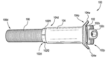
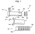
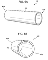
- a surgical access device can include an inner tube; and an outer tube having a distal end and a proximal end, and a hole formed therethrough, the hole being configured to receive the inner tube, wherein an external surface of the inner tube generates friction with the internal surface of the outer tube, and wherein movement of the inner tube distally and proximally relative to the outer tube is restricted by the friction generated by the external surface of the inner tube with the internal surface of the outer tube.
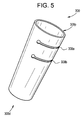
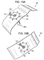
- an access device can include a tube having an opening formed therethrough from a distal end to a proximal end of the tube, the tube comprising one or more sets of cut regions along an external surface of the tube for separating the tube into a useable portion and a disposable portion, wherein the useable portion has a length configured to surgically access an area of a patient's body.
- the sets of cut regions can include one or more perforations.
- the sets of cut regions can be provided at fixed intervals along a portion of the length of the tube.
- Each of the sets of cut regions can be provided around the circumference of the external surface of the tube.
- Each of the sets of cut regions can be provided around less than the entire circumference of the external surface of the tube.
- Each of the perforations can penetrate through the tube from the external surface to the internal surface.
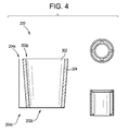
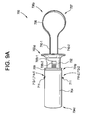
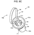
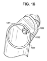
- the access device can include a ring portion comprising two or more concentric walls extending from a proximal end to a distal end of the ring portion, the two or more concentric walls being separated by a space configured to receive the proximal end of the tube.
- One of the two or more concentric walls can include one or more teeth features angled facing the proximal end of the ring portion. The one or more teeth can be configured to penetrate the external surface of the proximal end of the tube when the ring portion is in a mounted configuration.
- the ring portion can be placed in the mounted configuration by (i) sliding the tube between two of the two or more concentric walls, one of which includes the one or more teeth features, from the distal end of the ring portion toward the proximal end of the ring portion, and (ii) pulling the tube from the proximal end of the ring portion toward the distal end of the ring portion, causing the penetration of the one or more teeth into the external surface of the tube.
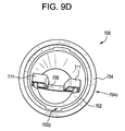
- the one of the two or more walls including the one or more teeth features can have the one or more teeth features disposed on a surface facing another of the two or more concentric walls.
- the two or more concentric walls can include an exterior wall, an interior wall and a middle wall provided between the exterior wall and the interior wall.
- the middle wall can be the one of the two or more concentric walls that includes the one or more teeth features.
- the one or more teeth features can be provided on an internal surface of the middle wall.
- a method of operating an access device can include identifying a target depth required to access a surgical site in a patient's body; adjusting the length of a surgical access device based on the identified target depth; and advancing a distal end of the surgical access device toward the surgical site in the patient's body.
- the adjusting the length of the surgical device can include removing a disposable portion of a tube of the surgical access device, by separating the disposable portion from the rest of the tube.
- the separating of the disposable portion can include twisting, bending or applying force against opposite sides of the tube of the surgical access device relative to a fixed pivot point.
- the fixed pivot point can be located at one of a set of cut regions disposed on the external surface of the tube.
- the set of cut regions can include one or more perforations. Each of the sets of cut regions can be provided around the circumference of the external surface of the tube. Each of the perforations can penetrate through the tube from the external surface to the internal surface.
- the method can include mounting a tube of the adjusted-length surgical device onto a ring portion.
- the mounting of the tube onto the ring portion can include sliding the proximal end of the tube in a distal end of the ring portion, toward a proximal end of the ring portion, the proximal end of the tube being slid between two walls of the ring portion; pulling the tube in a direction from the proximal end of the ring portion toward the distal end of the ring portion, wherein the pulling of the tube causes the teeth features disposed on a surface of a first wall among the two walls to grip the tube by penetrating into an external surface of the tube, the teeth features being disposed on the surface of the first wall facing a second wall among the two walls.
- the method can include stabilizing the surgical access device advanced into the surgical site of the patient's body by connecting a stabilizing feature of the ring portion to a corresponding stabilizing feature on an anchor device.
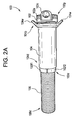
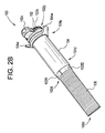
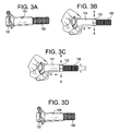
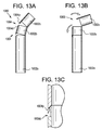
- a surgical access device can include an inner tube having an opening formed therethrough and a knob protruding from an external surface of the inner tube; and an outer tube having an opening formed therethrough and one or more slots connected by a path, the one or more slots and the path penetrating through an external and internal surface of the outer tube and being operable to receive the knob of the inner tube, wherein rotating the inner tube in a first direction relative to the outer tube causes the inner tube to be positioned in an adjustable-length configuration, in which the knob of the inner tube is slidably disposed along the path of the outer tube, and wherein rotating the inner tube in a second direction opposite the first direction relative to the outer tube causes the inner tube to be positioned in a fixed-length configuration, in which the knob of the inner tube is fixedly engaged within one of the one or more slots of the outer tube.
- a proximal end of the inner tube can include a handle, the handle being operable to control the rotating of the inner tube in the first and second directions.
- the opening of the outer tube can be configured to receive a first surgical tool.
- the outer tube can include a sub-tube protruding from the external surface thereof, the sub-tube being configured to receive a second surgical tool.
- the inner tube in the adjustable-length configuration can be advanced distally and proximally such that the knob slides along the path of the outer tube. Fixing the knob of the inner tube in each of the slots of the outer tube can cause the length of the surgical access device to be altered.
- a method for operating a surgical access device can include identifying a target depth required to access a surgical site in a patient's body; adjusting the length of a surgical access device based on the identified target depth; and advancing a distal end of the surgical access device toward the surgical site in the patient's body.
- the adjusting the length of the surgical access device can include rotating an inner tube of the surgical access device in first direction relative to an outer tube of the surgical access device, to position a knob protruding from an external surface of the inner tube within a path formed along the length of an outer tube, the inner tube being slidably engaged within the outer tube; advancing the inner tube distally or proximally relative to the outer tube, such that the knob of the inner tube slides along the path of the outer tube; rotating the inner tube in a second direction opposite the first direction relative to the outer tube, to position the knob of the inner tube within one of a plurality of slots formed along the length of the outer tube and extending from the path, wherein the positioning of the knob of the inner tube within one of the plurality of slots causes the proximal and distal position of the inner tube relative to the outer tube to be fixed.
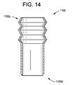
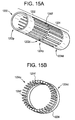
- a surgical access device can include an inner tube including one or more engagement features of a first type disposed on an outer surface thereof; and an outer tube telescopically mated with the inner tube, and including one or more engagement features of a second type formed at least on the inner surface thereof; wherein the first type of engagement features and the second type of engagement features are complementary to each other, and wherein a length of the surgical access device is adjusted by one of: (i) rotating the inner tube relative to the outer tube such that the one or more engagement features of the inner tube slide along the corresponding one or more engagement features of the outer tube, and (ii) applying opposite proximal or distal forces on the inner tube and outer tube, thereby causing engagement features of the inner tube to slip from the corresponding one or more engagement features of the outer tube to adjacent others of the one or more engagement feature of the outer tube.
- the one or more engagement features of the inner tube and the outer tube can form oblique angles relative to a longitudinal axis of the inner tube and/or the outer tube.
- the one or more engagement features of the inner tube and the outer tube can be formed of a deformable material enabling their slipping therebetween.
- the one or more engagement features of the inner tube and the outer tube can be formed around part or all of the circumference of the inner tube and the outer tube, respectively.
- a surgical access device can include an inner tube having a distal end, a proximal end, and an opening formed therethrough, the inner tube comprising one or more ratchet features disposed along part of a length of an exterior surface of the inner tube, the one or more ratchet features comprising one or more tooth features; and an outer tube having a distal end, a proximal end, and an opening formed therethrough, the opening at the proximal end of the outer tube being configured to receive the distal end of the inner tube, and the outer tube comprising a lip feature formed around the circumference of the proximal end of the outer tube, the lip feature being configured to engage with one or more of the tooth features of the one or more ratchet features of the inner tube, wherein a length of the surgical access device is adjusted by applying opposite proximal and distal forces on the inner and outer tubes causing the lip feature of the outer tube to slip over one or more of the tooth features of the one or more ratchet features of the inner tube
- Engaging the lip feature of the outer tube with one or more of the tooth features of the inner tube can cause the distal and proximal movement of the inner and outer tube, relative to each other, to be restricted.
- the proximal end of the inner tube can be cone-shaped and can flange proximally and externally relative to the rest of the of the inner tube.
- the external surface of the cone shaped portion of the inner tube can be configured to contact a surface of skin of a patient's body when the surgical access device is inserted in the patient's body.
- a circumference of the internal surface of the outer tube at the lip feature can be smaller than a circumference of the external surface of the inner tube at the one or more tooth features.
- the access device can include an auxiliary tool comprising a handle portion formed at a proximal end thereof, two or more prongs, and two or more tabs formed at corresponding distal ends of the two or more prongs, and the two or more prongs biased apart from one another, wherein the inner tube comprises one or more slots formed along part of the length of the inner tube, through the external and internal surfaces of the inner tube, wherein the outer tube comprises one or more slots formed along part of the length of the outer tube, through the external and internal surface of the outer tube, the one or more slots of the outer tube being shorter than the one or more slots of the inner tube, and wherein the auxiliary tool is engaged with the inner and outer tubes by squeezing the two or more prongs against their bias, proximally and distally moving the auxiliary tool along the opening of the inner tube, and releasing the two or more prongs causing their tabs to extend through the one or more slots of the inner tube and the one or more slots of the outer tube.
- the inner tube comprises one or
- the length of the surgical access device can be adjusted by proximally pulling or distally pushing the auxiliary tool when the tabs are extending through the one or more slots, causing distal or proximal force to be applied on the one or more slots of the outer tube and the distal and proximal position of the outer tube relative to the inner tube to change as the tabs slide along the one or more slots of the inner tube.
- the proximal pulling or the distal pushing of the auxiliary tool can cause the lip feature of the outer tube to slip over one or more of the tooth features of the inner tube.
- a method for adjusting a length of a surgical access device can include applying opposite distal and proximal forces on an inner tube and an outer tube of the surgical access device, the inner tube being slidably disposed within an opening of the outer tube, wherein the applying of the opposite distal and proximal forces causes a lip feature on an internal surface of a proximal end of the outer tube to slip past one or more tooth features of one or more ratchet features formed on an external surface of the inner tube; and terminating the opposite distal and proximal forces on the inner tube and the outer tube when the lip feature of the outer tube is engaged with one or more of the tooth features at a position in which the length of the surgical access device is equal to a desired length.
- a method for adjusting a length of a surgical access device can include applying distal or proximal force on an auxiliary tool positioned within an opening formed through an inner tube, the auxiliary tool comprising two or more prongs and or two or more corresponding tabs extending outwardly from distal ends of the two or more prongs through two or more slots formed through the inner tube and two or more slots formed through the outer tube, the two or more slots formed through the outer tube being shorter than the two or more slots formed through the inner tube, wherein applying the distal or proximal force on the auxiliary tool causes the two or more tabs to push or pull, respectively, against distal or proximal edges of the slots, such that the outer tube slides distally or proximally relative to the inner tube as the two or more tabs move distally or proximally along the one or more slots of the inner tube.
- the applying the distal or proximal force on the auxiliary tool can further cause a lip feature formed on an internal surface of a proximal end of the outer tube to skip over one or more tooth features of one or more ratchet features formed on an external surface of the inner tube.
- the distal and proximal movement of the outer tube relative to the inner tube can be restricted when the lip feature of the outer tube is engaged with one or more of the tooth features of the inner tube.
- the auxiliary tool can be positioned within the opening of the inner tube by: inwardly squeezing the two or more prongs against their bias, such that the distance between the two or more prongs is less than the diameter of the opening of the inner tube; distally or proximally moving the auxiliary tool within the opening of the inner tube; and releasing the two or more prongs such that their bias causes the two or more tabs of the two or more prongs to separate and extend through the two or more slots formed in the inner tube and the two or more slots formed in the outer tube.
- a surgical access device can include a tube-shaped body having an external surface and an internal surface, the internal surface forming an opening through the surgical access device from a distal end to a proximal end; a plurality of longitudinal slits formed through the body, extending distally from the proximal end; and a plurality of bendable arms formed longitudinally through the body of the surgical access device, extending distally from the proximal end, each of the plurality of bendable arms being defined by two of the plurality of slits, wherein the plurality of bendable arms are configured to be externally bent relative to a pivot point to adjust the length of the access device.
- the access device can include a ring wrapped around the external surface of the body, wherein the plurality of bendable arms are bent over a proximal end of the ring.
- the access device can include a stabilization material for fixing the position of the plurality of bendable arms on skin of a patient, the stabilization material comprising one or more of sutures, adhesive or tape.
- At least one of the plurality of bendable arms can engage with one or more posts having a fixed position relative to the body of a patient, the posts restricting the rotation of the one of the plurality of bendable arms.
- a method for adjusting a length of a surgical access device can include inserting a distal end of a surgical access device into a body of a patient, the surgical access device having a tube-shaped body; sliding a support ring distally along the body of the surgical access device such that a proximal end of the support ring is positioned above the surface of the skin of the patient; and bending one or more bendable arms against the proximal end of the support ring such that external surfaces of the one or more bendable arms are placed in contact with the skin of the patient, wherein the one or more bendable arms are formed longitudinally along the body of the surgical access device, extending distally from the proximal end of the surgical access device, the one or more bendable arms being separated by slits penetrating through the body of the surgical access device.
- the one or more bendable arms can be secured to skin using a stabilization object including one or more of an adhesive, tape and sutures. At least one of the one or more bendable arms can be positioned between two or more posts having a fixed position relative to the body of the patient, such that rotation of the at least one of the one or more bendable arms is prevented.
- a surgical access device can include an inner tube having a distal end and a proximal end, a hole formed therethrough from the distal end to the proximal end, and one or more first ribbed features wrapped around the circumference of at least part of an external surface of the inner tube; and an outer tube having a distal end and a proximal end, a hole formed therethrough from the distal end to the proximal end, and one or more second ribbed features wrapped around the circumference of at least part of an internal surface of the outer tube, the outer tube having the inner tube slidably engaged therein, wherein the one or more first ribbed features are configured to engage with the one or more second ribbed features, and wherein a length of the surgical access device is adjusted by applying opposite distal and proximal forces on the inner and outer tubes such that at least one of the one or more first ribbed features slips over at least one of the one or more second ribbed features.
- the distal and proximal positions of the inner and outer tube, relative to each other, can be fixed when the one or more first ribbed features are engaged with the one or more second ribbed features.
- the one or more first ribbed features and the one or more second ribbed features can be convex or concave structures.
- the access device can include a collar feature operable to connect to a stabilization object having a fixed position relative to a body of a patient or an object.
- a method for adjusting the length of a surgical access device can include applying a force to a first tube of the surgical access device, the force being a distal or proximal force relative to a second tube of the surgical access device; causing one or more ribbed features of the first tube to slide past one or more ribbed features of the second tube; and releasing the force applied to the first tube when the first tube has reached a position, relative to the second tube, in which a length of the surgical access device is equal to a target length.
- the first tube can be an inner tube having the one or more ribbed features formed on an external surface thereof.
- the second tube can be an outer tube having the one or more ribbed features formed on an internal surface thereof, the outer tube having the inner tube slidably engaged therein.
- the one or more ribbed features of the inner tube can be complimentary to the one or more ribbed features of the outer tube, such that distal and proximal movement of the inner and outer tubes relative to each other is prevented when the one or more ribbed features of the inner tube are engaged with the one or more ribbed features of the outer tube.
- a surgical access device can include a tube including a plurality of tube segments connected by interlocking snap features, the snap features including a protruding feature and a depression feature, wherein each of the plurality of tube segments includes at least one of a protruding feature and a depression feature, wherein at least one of the plurality of tube segment includes a protruding feature, and another of the plurality of tube segments adjacent to the one of the plurality of tube segments includes a depression feature, and wherein the one of the plurality of tube features and the adjacent tube feature are attached to one another by the protruding feature of the one tube segment being engaged with the depression feature of the adjacent tube segment.
- One tube segment can be detachable from the adjacent tube segment by disengaging the protruding feature of the one tube segment from the depression feature of the adjacent tube segment.
- the protruding feature of the one tube segment can be disengaged from the depression feature of the adjacent tube segment by applying a force to the protruding feature in a direction away from the depression feature.
- a surgical access device can include a tube having a distal end and a proximal end, and corrugated features along a portion of a length of the tube, the corrugated features being configured to be pulled and pushed to extend and retract the length of the tube.
- the corrugated features can be provided adjacent to the proximal end of the tube.
- a surgical access device can include a first tube having a proximal end and a distal end, the first tube including fingers extending from the proximal end to the distal end; a second tube having a proximal end and a distal end, the second tube including fingers extending from the distal end to the proximal end, wherein the fingers of the first tube and the fingers of the second tube being are spaced part from each other, and wherein the fingers of the first tube are configured to engage with the fingers of the second tube to fix the position of the first tube relative to the second tube.
- the size, shape and position of the fingers of the first tube can be equal to the size, shape and position of the fingers of the second tube.
- the fingers of the first tube can distally and proximally slide between the fingers of the second tube.
- the circumference of the first tube can be equal to the circumference of the second tube.
- FIG. 1 is a side view of one exemplary embodiment of a surgical access device, shown in a disassembled state;
- FIG. 2A is a side view of the surgical access device of FIG. 1 , shown in an assembled state;
- FIG. 2B is a perspective view of the surgical access device of FIG. 1 ;
- FIG. 2C is another perspective view of the surgical access device of FIG. 1 ;
- FIG. 3A is side view of the surgical access device of FIG. 1 in a locked position
- FIG. 3B is side view of the surgical access device of FIG. 1 in an unlocked position
- FIG. 3C is side view of the surgical access device of FIG. 1 , schematically illustrating a length adjustment of the access device;
- FIG. 3D is side view of the surgical access device of FIG. 1 in a locked position
- FIG. 4 is a sectional side view of another exemplary embodiment of a surgical access device
- FIG. 5 is a perspective view of another exemplary embodiment of a surgical access device
- FIG. 6A is a perspective view of an exemplary tube of another exemplary embodiment of a surgical access device
- FIG. 6B is another perspective view the tube of FIG. 6A ;
- FIG. 6C is a top view of an exemplary embodiment of a ring of the surgical access device of FIG. 6A ;
- FIG. 6D is a perspective view of the ring of FIG. 6C ;
- FIG. 6E is a another perspective view of the ring of FIG. 6C ;
- FIG. 7A is a perspective view of another exemplary embodiment of a surgical access device
- FIG. 7B is another perspective view of the surgical access device of FIG. 7A ;
- FIG. 7C is a bottom view of the surgical access device of FIG. 7A ;
- FIG. 7D is another perspective view of the surgical access device of FIG. 7A ;
- FIG. 8 is a perspective view of another exemplary embodiment of a surgical access device
- FIG. 9A is a side view of another exemplary embodiment of a surgical access device.
- FIG. 9B is a perspective view of the surgical access device of FIG. 9A ;
- FIG. 9C is another perspective view of the surgical access device of FIG. 9A ;
- FIG. 9D is another perspective view of the surgical access device of FIG. 9A ;
- FIG. 9E is an exploded perspective view of the surgical access device of FIG. 9A ;
- FIG. 10A is a perspective view of another exemplary embodiment of an access device, shown inserted through a skin surface of a patient and secured to a remote anchor point;
- FIG. 10B is another perspective view of the access device of FIG. 10A ;
- FIG. 10C is another perspective view of the access device of FIG. 10A ;
- FIG. 11A is another perspective view of the access device of FIG. 10A in a placement state
- FIG. 11B is another perspective view of the access device of FIG. 11A in a support ring placement state
- FIG. 11C is another perspective view of the access device of FIG. 11A in a state of bending the bendable arms;
- FIG. 11D is another perspective view of the access device of FIG. 11A in a state of attaching the bendable arms to the patient;
- FIG. 11E is another perspective view of the access device of FIG. 11A in a state of attaching a bendable arm to a remote anchor point;
- FIG. 12 is a sectional side view of another exemplary embodiment of a surgical access device
- FIG. 13A is a side view of another exemplary embodiment of a surgical access device, in a snapped-in configuration
- FIG. 13B is another side view of the surgical access device of FIG. 13A in an unsnapping configuration
- FIG. 13C is a sectional side view of a snap feature of the surgical access device of FIG. 13A ;
- FIG. 14 is a side view of another exemplary embodiment of a surgical access device
- FIG. 15A is a perspective view of another exemplary embodiment of a surgical access device
- FIG. 15B is a perspective view of an unattached tube of the surgical access device of FIG. 15A ;
- FIG. 16 is a perspective view of an exemplary connection feature of a surgical access device.
- Adjustable-length surgical access devices are disclosed herein, which can advantageously allow an overall length of the access device to be quickly and easily changed by the user.
- the access devices herein can reduce or eliminate the need to maintain an inventory of many different length access devices.
- the length of the access device can be adjusted while the access device is inserted into the patient. This can reduce or eliminate the need to swap in and out several different access devices before arriving at an optimal length access device. This can also reduce or eliminate the need to change the access device that is inserted into a patient as the depth at which a surgical step is performed changes over the course of a procedure. Rather, the length of the access device can be adjusted in situ and on-the-fly as needed or desired to accommodate different surgical depths.
- the present disclosure includes some illustrations and descriptions that include prototypes or bench models. A person skilled in the art will recognize how to rely upon the present disclosure to integrate the techniques, devices, and methods provided for into a product, such as a consumer ready, warehouse-ready, or operating room ready surgical device.
- Exemplary embodiments of the present disclosure provide surgical access devices, and more specifically, adjustable-length surgical access devices.
- the surgical access device can include one or more tubes or portions that can be manipulated to obtain a surgical access device of a desired length that is optimal or desirable to access a patient's surgical site of interest. Examples of such manipulations can include pulling, pushing, twisting, rotating, pivoting, folding, sliding, and/or combinations thereof.
- Engagement features provided on the surgical access device including, for example, on inner and outer surfaces thereof, can prevent, limit or restrict the lengthening and shortening of the surgical access device in certain circumstances, such as when the manipulations described above are performed with minimal or incidental force, e.g., below an identified force threshold.
- Such features can include grooves, threads, slots, protrusions, depressions, lips, and the like. Thus, the features can limit or prevent inadvertent lengthening and shortening of the surgical access device once the surgical access device has been configured to its desired length.
- the surgical access device can be or can include an enclosed tubular structure, a slotted or bladed retractor, a cannula, and so forth.
- the surgical access device can include a proximal end, proximate to a user of the surgical access device, and a distal end, proximate to the patient or the patient's surgical region.
- Formed through the surgical access device can be a hole or opening, extending from the proximal end to the distal end, defining a working channel through which implants, instruments, or other objects can be inserted to or removed from the patient's body.
- the surgical access device can include a body, which can refer to the structure that makes up the external and internal surfaces of the surgical access device.
- the internal surface of the body can define the working channel through the surgical access device.
- the surgical access device can be round, square, rectangular, or any other shape, as deemed necessary or desirable to access a patient's surgical region.
- the working channel formed through the surgical access device can be round, square, rectangular or any other shape, as deemed necessary or desirable to enable the insertion and removal of implants, instruments, or other objects for surgery.
- the thickness of the body of the surgical access device can vary, so long as the aspects described herein enabling length adjustment are retained.
- FIGS. 1, 2A to 2C, and 3A to 3D illustrate one exemplary embodiment of a surgical access device 100 configured to provide operative access to a patient's anatomy.
- the surgical access device 100 may be described with reference to its use to access a patient's intervertebral disc during spinal surgery, it should be understood that the surgical access device 100 can be configured and used in accordance with other surgical procedures to access to other surgical regions within a patient.
- the surgical access device 100 can include an upper tube 102 , a middle tube 104 , a lower tube 106 , and a spring 108 .
- FIG. 1 illustrates the disassembled parts or components of the access device 100 , namely the upper tube 102 , middle tube 104 , lower tube 106 , and spring 108 .
- the access device 100 is referred to as a “telescoping tube,” due to its being configured so that the upper, middle and lower tubes 102 , 104 , and 106 fit within one another in a way that allows them to slidably engage to enable the length of the access tube 100 to be extended and retracted.
- the upper tube 102 , middle tube 104 , and lower tube 106 can be referred to as a first inner tube, outer tube, and second inner tube, respectively, to describe their inner and outer positions in the assembled surgical access device 100 .
- the upper tube 102 , the middle tube 104 , the lower tube 106 , and the spring 108 can each include at least a portion that is substantially tubular or cylindrical.
- the upper tube 102 , the middle tube 104 , the lower tube 106 , and the spring 108 can be assembled into a length-adjustable surgical access device 100 that can be used to access the patient's anatomy during surgery.
- the distal end 102 d of the upper tube 102 can be inserted through the spring 108 .
- the distal end 102 d of the upper tube 102 once inserted through the spring 108 , can be inserted into the proximal end 104 p of the middle tube 104 .
- the proximal end 106 p of the lower tube 106 can be inserted into or within the distal end 102 d of the upper tube 102 .
- the middle tube 104 can be axially translated in a proximal direction relative to the upper tube 102 , against the bias of the spring 108 .
- one or more resilient fingers 102 f formed at the distal end of the upper tube 102 can expand radially-outward to disengage from the lower tube 106 , thereby allowing the lower tube 106 to translate axially relative to the upper tube 102 to set an overall length of the access device 100 .
- the middle tube 104 can be released, such that it returns distally under the bias of the spring 108 .
- the middle tube 104 can urge the fingers 102 f radially-inward into engagement with the lower tube 106 to fix the length of the access device 100 .
- the upper tube 102 can include a proximal end 102 p .
- the proximal end 102 p can include or can have formed thereon a stop 102 s configured to abut the proximal end 104 p of the middle tube 104 , to stop or prevent the middle tube 104 from excessive proximal movement relative to the upper tube 102 .
- the stop 102 s can extend radially about the proximal end 102 p of the upper tube 102 .
- the outer surface of the stop 102 s can have a circumference that is larger than (1) the circumference of the outer surface of the adjacent proximal end 102 p of the upper tube 102 , and (2) the circumference of the inner surface of the proximal end 104 p of the middle tube 104 .
- the outer surface of the stop 102 s can be textured with grooves and/or ridges to enhance its gripping qualities, thereby allowing the access device 100 to be more easily manipulated by a user, for example, to stabilize or twist the access device 100 .
- the stop 102 s can include a connector interface 102 c which can allow the position and/or orientation of the access device 100 to be fixed via a connector or other support (not illustrated).
- the connector interface 102 c can be built in to or can protrude outwardly from the stop 102 s .
- a connector can be used to connect the connector interface 102 c of the access device 100 to an ipsilateral or contralateral pedicle anchor or anatomical support, operating table, or other support or stabilizing feature (not illustrated).
- the connector interface 102 c can be used as a stabilizer portion during actuation of the access device 100 .
- the stop 102 s and/or the connector interface 102 c can be formed integrally with the upper tube 102 p , or can be manufactured as a separate component that is attachable to the upper tube 102 p.
- the upper tube 102 can include a distal end 102 d .
- the distal end 102 d can have formed thereon flexible fingers 102 f 1 and 102 f 2 (collectively “ 102 f ”) configured to engage with the lower tube 106 and limit or prevent the distal or proximal movement of the lower tube 106 relative to the upper tube 102 .
- the flexible fingers 102 f can be formed by slits (or cuts) formed in the body of the upper tube 102 , starting from the distal end 102 d toward the proximal end 102 p .
- the proximal end of the slits can include a circle or hole of larger diameter than the slits, to enable the fingers to more easily, and/or more widely, expand or deflect as explained below.
- the flexible fingers 102 f can include any number of fingers and can be created by one or more slits.
- the length of the slits on the body of the upper tube 102 can be the same or can vary.
- the length of the slits forming the fingers 102 f can be determined based on the length of the middle tube 104 and/or the lower tube 106 , on the amount of engagement that is desired between the upper tube 102 and the lower tube 106 , and/or on the amount of deflection or expansion of the fingers 102 f that is desired or to be allowed.
- the length of the slits forming the fingers 102 f can be equal to or greater than the difference in length between the upper tube 102 and the middle tube 104 .
- the length of the slits forming the fingers 102 f can be equal to or greater than the length of the outer surface of the upper tube 102 at the distal end 102 d that is exposed when the middle tube 104 is fully retracted.
- the length of the slits can be in the range of 1% to 33% of the length of the upper tube 102 (e.g., 1%, 5%, 10%, 15%, 20%, 25%, 30%, 33%).
- the inner surface of the upper tube 102 can include grooves or ridges that are congruent with, complementary to, or that mate with counterpart grooves or ridges on the outer surface of the lower tube 106 .
- the ridges or grooves can be spiral, circular or otherwise shaped to engage with counterpart features to limit or prevent movement of the upper and lower tubes 102 and 106 , relative to one another, in a lengthwise, proximal and distal direction.
- the grooves or ridges on the inner surface of the upper tube 102 can be formed on the distal end 102 d , e.g., on the fingers 102 f .
- the grooves and/or ridges can be referred to as complementary engagement features.
- the fingers 102 f can be actuated (e.g., expand, deflect, flare) by proximally retracting the middle tube 104 relative to the upper tube 102 , allowing the fingers 102 f to expand or flare outward in the direction A illustrated in FIGS. 3B and 3C , thereby increasing or enlarging the diameter of the opening of the upper tube 102 at the distal end 102 d where the fingers 102 f are formed.
- actuated e.g., expand, deflect, flare
- the increased diameter of the distal end 102 d can allow the lower tube 106 to slide or be moved distally and proximally relative to the upper tube 102 .
- a desired total length of the access device 100 can be set by releasing the middle tube 104 from its retracted position, causing the middle tube 104 to move distally relative to the upper tube 102 as a result of the bias of the spring 108 , and causing the fingers 102 f to retract (e.g., opposite of direction A) and the diameter of the opening of the distal end 102 d to decrease.
- the lower tube 106 can include a distal end 106 d and a proximal end 106 p .
- the diameter of the opening of the tube 106 formed by the inner surface can be the same at the distal end 106 d and at the proximal end 106 p .
- the external surface of the lower tube 106 can include or have formed thereon grooves (or ridges) that are configured to engage with matching, mating, or complementary grooves on the internal surface of the upper tube 102 .
- the grooves on the lower tube 106 can be provided at various regions along the length of the tube, as needed to achieve the desired length and stability characteristics of the access device 100 for its use in surgery.
- the outer surface of the lower tube 106 can have markings, writing and/or other indications thereon. Markings provided along the length of the outer surface of the lower tube 106 can indicate lengths or other measurements (e.g., of the access device 100 , of the lower tube 106 , etc.) when the upper tube 102 is fixedly engaged with the lower tube 106 .
- the length of the access device 100 can be the measurement marked on the external surface of the lower tube 106 at the position where the distal end 102 d of the upper tube 102 extends to.
- the middle tube 104 can be operated by proximal retraction and distal extension movements.
- the middle tube 104 can include a proximal end 104 p and a distal end 104 d.
- the proximal end 104 p of the middle tube 104 can include or can have formed thereon wings 104 w (or rings, handles, ears, or another similar structure) that allow a user of the access device 100 to retract, pull or otherwise move or slide the middle tube 104 toward the proximal end 102 p of the upper tube 102 .
- the wings 104 w can protrude or can be formed away from the external surface of the middle tube 104 .
- the wings 104 w or a portion thereof can extend away from the external surface of the middle tube 104 such that the wings 104 w form a right angle or an oblique angle with the outer surface of the middle tube 104 .
- the wings 104 w can form a curve away from the external surface of the middle tube 104 , such that the distal-most end of the wings 104 w are formed away from the distal end 104 d of the middle tube 104 .
- the dimensions, shape and other attributes of the wings 104 w can vary as needed to provide an area where the user's fingers (e.g., middle and pointer fingers) can engage and pull the middle tube 104 toward the proximal end 102 p of the upper tube 102 .
- the curvature and length of the wings 104 w can be determined and/or configured according to the average or maximum size of a human's index and/or middle fingers.
- other configurations of the wings 104 w such as rings, can be rings that are formed external to or protruding from the outer surface of the middle tube 104 and that have an opening with a circumference larger than the average or maximum size of a human's index and/or middle fingers.
- the access device 100 can include one or more wings 104 w.
- the spring 108 that is disposed between the middle tube 104 and the upper tube 102 can be compressed.
- the size (compressed and uncompressed) and amount of force needed to compress the spring 108 can be determined based on various factors including the typical user's preference, the amount of time and speed at which the spring decompresses from the compressed state, the length of the tubes 102 , 104 , and 106 , the material of the spring 108 , and/or the thickness of the spring 108 .
- the length of the spring 108 or the amount of lengthwise space that the uncompressed spring 108 covers when engaged with the upper tube 102 can be less than or equal to the difference in the length of the upper tube 102 and the middle tube 104 .
- the spring 108 can be configured such that the amount of force needed to compress the spring 108 is (1) high enough so that the spring 108 returns towards a resting state to drive the middle tube 104 distally relative to the proximal end 102 p of the upper tube 102 and maintain the set length of the access device 100 ; and (2) low enough so that the driving of the middle tube 104 distally relative to the proximal end 102 p of the upper tube 102 is slow and controlled enough to not significantly alter the position of the access device 100 (e.g., relative to a patient) or the position of the tubes 102 , 104 , and 106 relative to one another.
- the access device 100 can provide access to a patient's anatomy during surgery. Accordingly, the length of the access device 100 at its longest configuration can be large enough to reach an anatomical point of interest.
- each of the tubes 102 , 104 , and 106 can have a respective length such that, when the tubes 102 , 104 , and 106 are assembled together with the spring 108 to form the access device 100 , the desired total length of the access device 100 can be achieved.
- the length of the upper tube 102 can be greater than the length of the middle tube 104 and the lower tube 106 .
- the length of the middle tube 104 can be less than the length of the upper tube 102 and the lower tube 106 .
- the length of the lower tube 106 can be greater than the length of the middle tube 104 , and less than, equal to or greater than the length of the upper tube 102 .
- the length of the lower tube 106 and/or the length of the grooved portion of the outer surface of the lower tube 106 can be equal to or greater than the distance from a patient's skin (e.g., where an incision is made and the access device 100 inserted) to the part or area of the patient's anatomy to which access is required, such that when the lower tube 106 is the only one of the tubes 102 , 104 , and 106 that is inserted into the incision, the lower tube 106 can reach and access that part or area of the patient's anatomy.
- the openings or working channel created by the inner surfaces of the tubes 102 , 104 , and 106 can be large enough to enable objects (e.g., implants, instruments, or other objects) to be moved therethrough, to and from the distal end 100 d and the proximal end 100 p of the access device 100 .
- the diameter and/or circumference of the opening of each of the tubes 102 , 104 , and/or 106 can vary from their distal ends to their proximal ends
- the upper tube 102 can be configured such that the diameter or circumference of the opening at the proximal end 102 p is larger than the diameter or circumference, respectively, of the opening at the distal end 102 d .
- the openings of the tubes 102 , 104 , and/or 106 can gradually narrow or expand along their lengths.
- the circumference of the opening of the middle tube 104 (at the proximal end 104 p and the distal end 104 d ) can be larger than the circumference of the outer surface of the upper tube 102 (at the distal end 102 d and the proximal end 102 p ), such that the distal end 102 d of the upper tube 102 can be inserted through the opening at the proximal end 104 p of the middle tube 104 and through the entirety of the length of the middle tube 104 , exiting at the distal end 104 d .
- the circumference of the opening of the middle tube 104 can be larger than the circumference of the outer surface of the lower tube 106 .
- the circumference of the opening of the upper tube 102 at the distal end 102 d and/or along the length of the fingers 102 f , when the fingers 102 f are in a radially-inward position, can be equal to or smaller than the circumference of the outer surface of the lower tube 106 ; and the circumference of the opening of the upper tube 102 at the distal end 102 d and/or along at least a portion of the length of the fingers 102 f , when the fingers 102 f are at an expanded or radially-outward position, can be larger than the circumference of the outer surface of the lower tube 106 .
- the circumference of the opening of the spring 108 can be larger than the circumference of the outer surface of the upper tube 102 .
- FIGS. 3A to 3D illustrate a process for using and/or adjusting the length of the access device 100 according to an exemplary embodiment.
- the access device 100 can be actuated by (1) retracting the middle tube 104 relative to the upper tube 102 , similar to a syringe; (2) adjusting the exposed length of the lower tube 106 ; and (3) releasing the middle tube 104 .
- FIG. 3A illustrates the access device 100 in a default or locked state in which the length of the access device is fixed.
- the spring 108 (not shown in FIG. 3A ) can urge the middle tube 104 distally relative to the upper tube 102 . That is, the proximal end 104 p of the middle tube 104 can be forced to its furthest position from the proximal end 102 p of the upper tube 102 by the bias of the spring 108 . In this position, the internal surface of the middle tube 104 can maintain the fingers 102 f of the upper tube 102 in a radially-inward position in which they engage with the grooves or other engagement features of the lower tube 106 .
- a small part e.g., 1%, 2%, 5%, 10%, 15%
- a small part e.g., 1%, 2%, 5%, 10%, 15%
- the access device 100 can be actuated by pulling, retracting or otherwise proximally moving or sliding, relative to the upper tube 102 , in the direction B, the middle tube 104 toward the proximal end 102 p of the upper tube 102 , as shown in FIG. 3B .
- the actuation of the access device 100 can be performed by applying a pushing pressure or force on the proximal end 102 p (or stop 102 s ) of the upper tube 102 (e.g., by a user's thumb), and applying an opposite pulling pressure or force on the wings 104 w of the middle tube 104 (e.g., by the user's index and middle finger), against the bias of the spring 108 .
- the middle tube 104 When the middle tube 104 is in the retracted position, as shown in FIGS. 3B and 3C , the distal end 104 d of the middle tube 104 is moved toward the proximal end 102 p of the upper tube 102 . Because the upper tube 102 is longer than the middle tube 104 , such a proximal retraction of the middle tube 104 can cause the fingers 102 f of the upper tube 102 to become exposed. When the fingers 102 f are exposed and no longer compressed by the inner surface of the middle tube 104 , the fingers 102 f can be free to expand in the direction A.
- the flaring or expanding of the fingers 102 f can cause the diameter of the opening at the distal end of the upper tube 102 and/or the circumference of the inner surface of the upper tube at the fingers 102 f to increase in size (e.g., to a size larger than the diameter or circumference of the lower tube 106 ). This can cause the fingers 102 f and the lower tube 106 to no longer be engaged or fixedly positioned, thereby allowing the lower tube 106 to be slid or translated proximally or distally relative to the distal end 102 d of the upper tube 102 , as shown in FIG. 3C .
- the lower tube 106 can continue to be moved proximally and distally so long as the access device 100 is actuated (e.g., the middle tube 104 remains in the retracted position).
- the proximal or pulling force on the middle tube 104 and/or the distal or pushing force on the upper tube 102 can be released, causing the upper tube 102 and the middle tube 104 to return towards their default positions, and the fingers 102 f to be compressed by the internal surface of the middle tube 104 , such that the position of the lower tube 106 relative to the upper tube 102 becomes fixed.
- the spring 108 can expand, causing the middle tube 104 to move distally, away from the proximal end 102 p of the upper tube 102 .
- the previously exposed fingers 102 f can become unexposed by sliding within the inner surface of the distal end 104 d of the middle tube 104 .
- the fingers 102 f can compress, causing the ridges or grooves on the inner surface of the fingers 102 f to engage with the ridges or grooves on the outer surface of the lower tube 106 , thereby locking or preventing the distal or proximal movement of the lower tube 106 relative to the upper tube 102 .
- the resulting access device 100 can have a length that is determined based on the selected amount of exposed area of the lower tube 106 , as set by the position where the lower tube 106 is locked.
- the access device 100 can then be used to access a target or desired area of the patient's anatomy located at a distance that is reachable by the access device 100 having been set at a desired length.
- FIG. 4 illustrates another exemplary embodiment of a surgical access device 200 .
- the surgical access device 200 can include an inner tube 202 and an outer tube 204 .
- the inner tube and the outer tube can have respective proximal ends ( 202 p , 204 p ) and distal ends ( 202 d , 204 d ), and holes or openings formed therethrough from their distal ends to the proximal ends to define a working channel through the access device.
- the inner tube 202 can be slidably disposed within the outer tube 204 —e.g., within the opening of the outer tube 204 to define a telescoping access device.
- the inner tube 202 and the outer tube 204 can be configured such that sufficient friction is created between the external surface of the inner tube 202 and the internal surface of the outer tube 204 to maintain a relative longitudinal position of the inner and outer tubes.
- the inner tube 202 can have an external surface with a circumference equal to or substantially equal to the circumference of the opening or internal surface of the outer tube 204 .
- opposite pulling and pushing forces can be applied to the tubes 202 and 204 to overcome the frictional force and axially translate the tubes relative to one another to shorten or lengthen the access device.
- the friction between the tubes 202 and 204 can be effective to restrict the proximal and distal movement of the tubes 202 and 204 and to maintain the device 200 at the adjusted length.
- the inner and outer tubes 202 , 204 can be rotationally fixed relative to one another, e.g., such that they inner and outer tubes cannot rotated with respect to one another about a central longitudinal axis of the device 200 .
- the tubes 202 , 204 can be rotationally fixed in various ways, such as by engagement between counterpart longitudinal rails and grooves, a pin-in-slot arrangement, or the like.
- FIG. 5 illustrates another exemplary embodiment of a surgical access device 300 configured to provide operative access to a patient's anatomy.
- the surgical access device 300 can include a tube or body having an opening or working channel formed therethrough from a distal end 300 d to a proximal end 300 p .
- the working channel can be defined by an inner surface of the surgical access device 300 .
- the working channel can be round, square, rectangular, and/or various other shapes, and can have a diameter or circumference of any size, so long as objects (e.g., implants, instruments, or other objects) can be moved to and from the proximal end 300 p and the distal end 300 d .
- objects e.g., implants, instruments, or other objects
- the shape, diameter, and/or circumference of the working channel can change between the distal end 300 d and the proximal end 300 p .
- the opening at the distal end 300 d can be smaller or narrower than the opening at the proximal end 300 p of the surgical access device 300 .
- the shape of the access device 300 which is defined by its external surface, can match the shape of the opening (e.g., circle, rectangle, square), or can have a shape that is different than that of the opening.
- the surgical access device 300 can be manufactured at a single maximum length determined to reach the deepest area of interest of a patient's body to be accessed during surgery. However, to enable the surgical access device 300 to be used at various lengths as needed to optimally or desirable access shallower regions in a patient's body, the access device 300 can include one or more slits or perforations 308 around at least part of the circumference of the external surface of the access device 300 , which facilitate the breaking (e.g., splitting, tearing, separating) of the access device 300 into multiple parts.
- the perforations 308 can have regions (e.g., circular perforations) that are larger in diameter than the rest of the slits of the perforations, to provide for easier breaking thereat.
- Breaking the access device 300 into multiple parts can be achieved in various ways, such as by twisting the access device 300 at opposite sides of the selected perforation 308 , or bending, folding or applying force to the access device at opposite sides of the selected perforation 308 , e.g., about a fixed pivot point equal to the position of the selected perforation 308 on the access device 300 .
- the access device 300 can include a plurality of perforations 308 a and 308 b formed around part of the circumference of the access device at various positions along the length of the access device 300 . Although only two perforations ( 308 a and 308 b ) are illustrated in FIG. 5 , any number of perforations can be provided on the access device 300 .
- the perforations can be provided at regular or irregular intervals along the length of the access device 300 .
- the perforations can be provided starting at the distal end or at the proximal end of the access device 300 .
- the perforations 308 can be provided around less than the entire circumference of the access device 300 (e.g., 10%, 25%, 33%, 50%, 75%).
- the perforations can be provided around a part of the circumference of the access device 300 that sufficient to allow for manual breakage of the access device 300 into multiple parts, preferably without any machine or tool assistance.
- the length, depth, and width of the perforations 308 can vary between individual perforations on the access device 300 , or between different access devices, as deemed necessary or desirable to enable manual breakage.
- the length, depth, and width of the perforations 308 can be based on the properties of the material used to manufacture the access device 300 , the thickness of the body of the access device 300 , the circumference of the access device 300 , or other parameters.
- the perforations 308 can have a length or other measurement associated therewith and marked on the external surface of the access device 300 . These markings can allow a user to identify the resulting length of the access device 300 when the access device is broken at the respective perforation 308 .
- the access device 300 can be configured such that, when it is broken into multiple parts, either the distal end or the proximal end of the original full-length access device 300 can be the resulting access device 300 to be used to access a part of a patient's body.
- the access device 300 can be provided without perforations, such that the access device 300 is instead cut at a desired region or length using a machine or tool.
- the access device 300 can include lines or markings indicating different measurements or lengths at which the access device can be cut using a machine or tool, thereby enabling identification of the resulting length of the access device 300 after it is cut into multiple parts.
- FIGS. 6A to 6E illustrate another exemplary embodiment of a surgical access device 400 .
- the access device 400 can include a main body or tube 402 and a ring portion 404 .
- the main body 402 can be cut, torn, or broken to the desired length, and the ring portion 404 can be attached thereto, e.g., to provide an anchoring point for stabilizing the main body or to cover the broken end of the main body.
- the tube 402 can be the access device 300 described above, for example, after having been split or cut into multiple parts to obtain a tube of a resulting optimal or desirable size for accessing a patient's target area.
- the tube 402 can include an opening or working channel formed therethrough, from a proximal end 402 p to the distal end 402 d .
- the shape and size of the opening defined by the inner surfaces of the tube 402 , can vary, as described herein.
- the shape and size of the opening can vary throughout the length of the tube 402 .
- the size of the opening can narrow from the proximal end 402 p to the distal end 402 d .
- the shape and size of the access device 400 as defined by its external surfaces, can also vary as described herein.
- the ring portion 404 of the access device 400 can be attached or mounted onto the proximal end 402 p of the tube 402 .
- the proximal end 402 p of the tube 402 can be the cut end of a tube after being cut or divided as described above in connection with FIG. 5 .
- the ring 404 when attached to the tube 402 , can provide enhanced handling and stabilizing of the access device 400 as explained in further detail below.
- the ring 404 can include a proximal side 404 p and a distal side 404 d .
- the ring 404 can include one or more concentric walls, e.g., an exterior wall 404 e , an interior wall 404 i , and a middle wall 404 m as shown.
- the exterior, interior and middle walls 404 e , 404 i , and 404 m can extend distally from the proximal end 404 p , lengthwise, to a length deemed sufficient to stabilize the tube 402 and the ring 404 when they are engaged.
- the length of the walls 404 e , 404 i and/or 404 m can be based on the length of the tube 402 . That is, the walls 404 e , 404 i and 404 m can have a length proportional to the length of the tube 402 .
- the length of the walls 404 e , 404 i , and 404 m can vary in size between each other.
- the proximal side 404 p of the ring 404 can be covered or sealed between the external wall 404 e and the internal wall 404 , such that the spaces between the walls 404 e , 404 i and 404 m cannot be accessed from a proximal-to-distal direction.
- the part of the proximal side 404 p that is internal or within the internal wall 404 i can be open, such that an opening is created through the proximal end 404 p to the distal end 404 d of the ring 404 .
- the distal side 404 d of the ring 404 can be exposed, allowing the spaces between the walls 404 e , 404 i , and 404 m to be accessed or entered from a distal-to-proximal direction, for example, to mount the ring 404 onto the tube 402 as explained in further detail below.
- the interior wall 404 i can have a smaller circumference than the middle wall 404 m and the exterior wall 404 e .
- the middle wall 404 m can have a circumference smaller than that of the exterior wall 404 e and larger than that of the interior wall 404 i .
- the middle wall 404 m can be a fully-closed circle.
- the middle wall 404 m can be made up of or can include intermittent or spaced apart wall portions (e.g., 404 m - 1 , 404 m - 2 , etc.) that extend distally from the underside of the ring 404 , and that form the wall 404 m .
- the wall portions can be referred to as “fingers” that extend distally from the distal-facing side of the proximal end 404 p of the ring 404 .
- the wall portions of the wall 404 m can be flexible and/or resilient such that their distal ends can move radially-inward or radially-outward.
- the wall portions can flex or deflect away from the interior wall 404 i and toward the external wall 404 e when pressure is applied thereto as a tube 402 is inserted into the space between the middle wall 404 m and the internal wall 404 i .
- Such flexibility of the wall portions can enable insertion of a tube 402 having a thickness equal to or larger than the space between the middle wall 404 m and the interior wall 404 i , when the wall portions are not deflected from their resting position, to be inserted therebetween.
- An internal surface of the middle wall 404 m (e.g., the surface of the middle wall 404 m facing the internal wall 404 i ), and or an outer surface of the internal wall can include one or more slits, teeth, or other surface features for engaging the tube 402 .
- the surface features can be directional, e.g., unidirectional, such that the surface features allow insertion of the tube 402 in a proximal direction but resist or prevent removal of the tube 402 in a distal direction.
- the surface features can include teeth that are angled facing toward the proximal side 404 p of the ring 404 .
- the distal-most ends of the teeth of the middle wall 404 can contact and slide along the external surface of the proximal end 402 p of the tube 402 .
- pulling the tube 402 in a distal direction away from the ring 404 can cause the teeth of the wall 404 m to penetrate the body of the tube 402 , thereby creating or increasing a grip of the ring 404 on the tube 402 .
- the space between the middle wall 404 m and the internal wall 404 i can be measured from the distal end of the teeth of the middle wall 404 m to the external surface of the internal wall 404 i .
- the ring 404 can include only an external wall 404 e and an internal wall 404 i , without a middle wall 404 m .
- the teeth of the middle wall 404 m described above can be provided in the internal surface of the external wall 404 e
- the space between the external wall 404 e and the internal wall 404 i can be configured similar to the space between the middle wall 404 m and the internal wall 404 i described above, to receive the proximal end 402 p of the tube 402 .
- the access device 400 can be more easily gripped by virtue of the larger size of the ring 404 compared to the tube 402 .
- the access device 400 can be stabilized using a stabilization feature 405 provided on the ring 404 .
- the stabilization feature 405 can be a structure extending away from the external-facing side of the external wall 404 e , and can be shaped in various ways.
- the stabilization feature 405 can be used to connect or attach the access device 400 to an ipsilateral or contralateral pedicle anchor or anatomical support, to a connector, operating table, or other support feature, which can provide stabilization of the access device.
- the stabilization feature 405 can be shaped like a ball, e.g., in order to connect with a support via a ball and socket joint configuration.
- FIGS. 7A to 7D illustrate another exemplary embodiment of a surgical access device 500 .
- the surgical access device 500 can include an inner tube 502 and an outer tube 504 .
- the inner tube 502 and the outer tube 504 can include openings or working channels formed to and from their respective proximal and distal ends.
- the openings of the inner and outer tubes 502 and 504 defined by their respective inner surfaces, can vary in size and shape, as described above.
- the size and shape of the inner and outer tubes 502 and 504 as defined by their external surfaces, can likewise vary in size and shape, as described above.
- the inner and outer tube 502 and 504 can have similar shapes, and can be sized such that the internal surface of the outer tube 504 has a circumference slightly larger than the circumference of the external surface of the inner tube 502 , such that the inner tube 502 can slide within the opening of the outer tube 504 without allowing any or a substantial amount of movement of the inner tube 502 other than along distal and proximal directions.
- the access device 500 can includes a turn-advance-turn-lock mechanism having a plurality of slots 506 - 1 , 506 - 2 , etc. (collectively “ 506 ”) formed on the outer tube 504 and a knob 508 or a similar protrusion formed on the inner tube 502 .
- the slots 506 can be formed in the inner tube 502 and the knob 508 can be formed on the outer tube 504 .
- the knob 508 can be a feature protruding from an external surface of the inner tube 502 .
- the knob 508 can have a shape and size that matches the shape and size of the slots 506 , such that the knob 508 can be slid into one of the slots 506 to prevent or resist relative distal and proximal movement between the inner and outer tubes.
- the thickness of the knob e.g., the distance which the knob protrudes from the external surface of the inner tube 502
- the thickness of the knob can be at least equal to the thickness of the body of the outer tube 504 , as measured from its external surface to its internal surface. While the knob 508 can be provided in any position on the tube, in some embodiments, the knob 508 can be provided on or proximate to the distal end of the inner tube 502 , enabling the length of the access device 500 to be maximized.
- the access device 500 can include a handle 512 for controlling the sliding and rotation of the inner tube 502 in the manner described in further detail below, and/or for securing the access device 500 to a support in the manner described herein.
- the slots 506 of the access device 500 can be formed as holes or perforations through the external and internal surfaces of the outer tube 504 .
- the slots 506 can be formed at regular or irregular intervals along the length of the outer tube 504 .
- the slots 506 can be disposed in the same line as the proximal and distal length of the outer tube 504 .
- the slots 506 can be connected by a path 507 , which can enable movement of the knob 508 between the slots 506 .
- eight slots 506 are shown in FIGS. 7A to 7D , the outer tube 504 can include any number of slots.
- the path 507 can be an elongate slot having a longitudinal axis that is parallel or substantially parallel to the longitudinal axis of the access device 500 .
- the slots 506 can be defined as lateral or circumferential extensions of the path 507 , and can extend perpendicular to or obliquely from the path 507 .
- the outer tube 504 can include a sub-tube 510 , which can be a tube that is formed on the external surface of the outer tube 504 .
- the sub-tube 510 can be of a smaller size (e.g., length, circumference, and/or other dimensions) and/or shape as the outer tube 504 .
- the size and shape of the sub-tube 510 can change from its distal end 510 d to its proximal end 510 p .
- An opening or working channel can be formed through the sub-tube 510 , to and from its proximal and distal ends 510 p and 510 d .
- the opening can be configured to provide supplemental access to the patient's surgical area.
- the supplemental access provided by the opening can be used to insert an object or tool different than the object or tool inserted through the opening of the outer tube 504 .
- Such separation of openings can be used when it is optimal to maintain the tools or objects separate from one another during surgery.
- a camera system can be inserted through the sub-tube 510 .
- the inner tube 502 can be inserted into the outer tube 504 .
- the inner and outer tubes 502 and 504 can be manufactured or produced such that the inner tube 502 is pre-inserted into the outer tube 504 .
- the inner and outer tubes 502 and 504 can be moved or positioned relative to each other, and the desired length locked or fixed by inserting the knob 508 into one of the slots 506 .
- the inner tube 502 can be rotated about its central longitudinal axis relative to the outer tube 504 (in a clockwise direction C when viewed from a proximal vantage point) until the knob 508 is positioned on the path 507 and/or adjacent to the edge of the path 507 that is opposite the slots 506 . With the knob 508 positioned on the path 507 , the inner tube 502 can be moved distally or proximally, relative to the outer tube 504 , along illustrated directions D and P.
- the inner tube 502 When the inner and outer tubes 502 and 504 are positioned such that the access device 500 is of a desired length, the inner tube 502 can be rotated about its central longitudinal axis relative to the outer tube 504 (in a counterclockwise direction C′ when viewed from a proximal vantage point). Rotation of the inner tube 502 in a counterclockwise direction can cause the knob 508 of the inner tube 502 to slide from the path 507 into an adjacent one of the slots 506 .
- the inner tube 506 can be further moved distally or proximally to slide the knob 508 into one of the those two slots 506 (e.g., the slot closest to the knob 508 ).
- the inner tube 502 can be moved and rotated along directions C, C′, P, and D using the handle 512 .
- the distal end of the access device 500 can be inserted into a patient's body to reach a desired surgical region, without causing the length of the access device 500 to be modified. That is, the shape of the slots 506 can prevent the distal, proximal, and counterclockwise movement of the inner tube 502 and/or its knob 508 relative to the outer tube 504 .
- the length of the access device 500 can be adjusted in the same fashion, by rotating (e.g., clockwise) the inner tube 502 , sliding it proximally or distally to achieve a desired length, and rotating the inner tube in the opposite direction (e.g., counterclockwise) to lock its position in another one of the slots 506 .
- the illustrated access device 500 is configured such that the outer tube 504 is generally distal to the inner tube 502 . In other arrangements, the inner tube 502 can be generally distal to the outer tube 504 .
- FIG. 8 illustrates another exemplary embodiment of a surgical access device 600 .
- the surgical access device 600 can include an inner tube 602 and an outer tube 604 that are telescopically mated to one another and that define a working channel therethrough.
- the inner and outer tubes 602 , 604 can include engagement features configured to maintain a relative longitudinal position of the inner and outer tubes.
- the engagements features can be threads that allow an overall length of the access device 600 to be adjusted by threading the inner tube 602 into or out of the outer tube 604 .
- the engagement features can be configured to slip or skip when sufficient force is applied thereto. Accordingly, gross length adjustment can be achieved by simply pushing or pulling the inner and outer tubes with sufficient force to overcome the engagement features. Fine length adjustment can be achieved by threading the tubes into or out of one another.
- An external surface of the inner tube 602 and an internal surface of the outer tube 604 can include complementary threads or similar engagement features.
- the threads can spiral around all or a part of the circumference of the external surface of the inner tube 602 and the internal surface of the outer tube 604 .
- the threads can be formed as an interrupted spiral thread, as shown, having a plurality of gaps between thread segments.
- the threads can be complementary to each other, such that a male or external thread on one of the tubes 602 or 604 engages with a female or internal thread on the other of the tubes 602 or 604 .
- the threads can be provided on any amount of length on the tubes 602 and 604 .
- the length of the surgical access device 600 can be adjusted in one or more ways.
- one way to adjust the length of the surgical access device 600 can be by pulling or pushing, in opposite proximal and distal directions, the inner tube 602 and the outer tube 604 , with sufficient force to cause the thread of one of the tubes 602 or 604 to skip or slip over the thread of the other of the tubes 602 or 604 .
- the pulling or pushing can be repeated in order to skip or slip as many threads as needed to place the inner and outer tubes 602 and 604 in a position relative to one another that results in the desired length of the access device 600 .
- One or both tubes 602 , 604 , or the engagement features thereof can be formed from a flexible or deformable material to facilitate such slipping.
- the dimensions or material properties of the tubes 602 and 604 , or the engagement features thereof, can be selected to ensure that threads are not slipped or skipped when minimal or incidental force or pressure is applied on the tubes 602 and 604 .
- Another way to adjust the length of the surgical device can be to rotate the inner tube 602 clockwise or counterclockwise relative to the outer tube 604 , e.g., about a central longitudinal axis of the access device 600 .
- Rotating the inner tube 602 relative to the outer tube 604 can cause the threads of the inner and outer tubes 602 and 604 to advance into or out from one another to adjust an overall length of the access device 600 .
- This manner of adjusting the length of the access device 600 can be more controlled and/or can allow for more precise small incremental length adjustment as compared with the above described thread skipping or sliding.
- the tubes 602 and 604 can be mated in a slight interference fit to resist or prevent relative rotation of the inner and outer tubes 602 and 604 when minimal or incidental rotational force is applied thereto.
- the access device 600 When the access device 600 has been adjusted to have a desired length, the access device can be inserted into a patient's body to access a surgical region. The length of the access device 600 can also be adjusted while the access device is inserted into a patient.
- FIGS. 9A to 9E illustrate another exemplary embodiment of a surgical access device 700 .
- the access device 700 can include an inner tube 702 , an outer tube 704 , and an auxiliary tool 706 .
- the length of the surgical access device 700 can be adjusted by moving the inner tube 702 proximally and distally relative to the outer tube 704 , and locking the position of the inner tube 702 relative to the outer tube using the auxiliary tool 706 .
- the inner tube 702 and the outer tube 704 can include openings or working channels formed therethrough, to and from their distal and proximal ends 702 d and 704 d , and 702 p and 704 p , respectively.
- the circumference of the opening of the outer tube 704 at the proximal end 704 p can be larger than the circumference of an external wall of the inner tube 702 at the proximal end 702 p , such that the inner tube 702 can be disposed within the outer tube 704 to form a telescoping, slidable engagement therebetween.
- the proximal end 702 p of the inner tube 702 can include or can be formed into a cone-shaped portion or flange.
- the flange can serve as a stop portion to prevent the distal movement of the inner tube 702 , relative to the outer tube 704 , beyond the inner tube's proximal end 702 p .
- Such a flanging structure of the proximal end 702 p of the inner tube 702 can also allow the proximal end of the inner tube 702 to be positioned tightly on the surface of the skin of a patient when the access device 700 is inserted into the patient's body.
- the inner tube 702 can include one or more ratchet features 705 disposed or formed on the length of the external surface of the inner tube 702 .
- the ratchet features 705 can be disposed on diametrically opposed sides of the external surface of the inner tube 702 .
- the ratchet features 705 can include a plurality of tooth features ( 705 t - 1 , 705 t - 2 , etc.; collectively referred to as “ 705 - t ”), which can define male engagement features protruding from the external surface of the inner tube 702 .
- the tooth features 705 t of the ratchet 705 can be configured to engage with or be received within a lip, groove, gap or other like structure 709 formed in the internal surface of the outer tube 704 , as described in further detail below.
- the tooth features 705 t can be formed along part or the entire length of the inner tube 702 .
- the tooth features 705 t can be formed along part of the external surface of the inner tube 702 starting at a lengthwise position proximate to the proximal end 702 p of the inner tube 702 .
- the size and shape of the tooth features 705 t can vary.
- the distance or spacing between tooth features 705 t can be the same or vary between each of the tooth features 705 t .
- the shape (e.g., curve, square, triangle), thickness (e.g., amount of protrusion away from the external surface), spacing and/or height (e.g., distance spanned across the length of the external surface of the inner tube 702 by each tooth) of the tooth features 705 t can depend on the shape, thickness, distance and/or height of the lip 709 formed on the internal surface of the outer tube 704 and vice versa.
- the width of the tooth features 705 t can be the same or vary between each of the tooth features, and they can spread over part or the entire circumference of the external surface of the inner tube 702 .
- the outer tube 704 can include an annular groove or lip 709 for engaging with the ratchet 705 and/or its tooth features 705 t .
- the lip 709 can be provided around part or the entire circumference of the internal surface of the outer tube 704 .
- the lip 709 can be formed at or proximate to the proximal end 704 p of the outer tube 704 , such that, when engaged with the inner tube 702 , the resulting length of the access device 700 can benefit from the rest of the length of the outer tube (e.g., from the lip 709 at the proximal end 704 p to the distal end 704 d ).
- the lip 709 can engage with the tooth features 705 t to limit or prevent distal and proximal movement of the inner tube and the outer tube 702 and 704 relative to each other.
- the lip 709 can be a concave feature such as a groove or gap formed on the internal surface of the outer tube 704 , extending from the internal surface toward the external surface of the outer tube 704 such that the groove or gap is of sufficient depth to accommodate part or all of a tooth feature 705 t .
- the lip 709 can be formed by the shape of the proximal end 704 p of the outer tube 704 .
- the internal surface of the outer tube 704 where the cone shape ends and meets the rest of the internal surface of the outer tube can be convex and/or have a smaller circumference than the rest of the outer tube 704 .
- This narrower or convex portion of the internal surface of the outer tube 704 can be configured to have a circumference smaller than the circumference of the outer-most portion of the tooth features 705 t and larger than the circumference of the external surface of the inner tube 702 at the regions between the tooth features 705 t .
- Such a configuration can allow the narrower portion of the internal surface of the outer tube 704 to be received between two of the tooth features 705 t , fixing the position of the outer tube 704 and limiting or preventing the distal and proximal movement of the inner and outer tubes 702 and 704 relative to one another when minimal or incidental force is applied in a proximal or distal direction to the inner and/or outer tubes 702 , 704 .
- force can be applied to the inner tube 702 and the outer tube 704 in opposite distal or proximal directions.
- pulling the inner tube 702 away from the outer tube 704 pulling the inner tube 702 proximally and the outer tube 704 distally, or pushing the inner tube 704 distally toward the outer tube 704 , with sufficient force, can cause the lip 709 on the internal surface of the outer tube 704 to skip or slip past one or more of the tooth features 705 t .
- the pulling and/or pushing of the tubes 702 and/or 704 can be repeated until the lip is fixedly engaged with one or more of the tooth features 705 t at a position where the access device 700 is at a desired length.
- the amount of force needed to slip or skip the lip 709 past a tooth feature 705 t can depend on various factors, including the size and/or shape of the lip 709 and/or tooth features 705 t , and/or the material of the inner and outer tubes 702 and 704 .
- An auxiliary tool 706 can be included in the access device 700 to facilitate extension or retraction of the tubes 702 , 704 relative to one another.
- the auxiliary tool 706 can be provided as a length-adjustment feature in addition or alternative to the ratchet 705 .
- the auxiliary tool 706 can include a handle portion 707 on the proximal end 706 p of the auxiliary tool 706 .
- the auxiliary tool 706 can include two prongs 710 ( 710 - 1 , 710 - 2 ) that extend distally from the handle 707 .
- the distal end of the prongs 710 can include or can be formed as tabs 711 that curve or bend away from one another in a radially-outward direction.
- the length of the tabs e.g., the distance that the tabs 711 extend away from their respective prongs 710
- other of their dimensions e.g., width, thickness
- the tabs 711 can be configured such that they can penetrate through the slots 712 and 714 .
- the auxiliary tool 706 can be designed such that it is self-spreading, meaning that the prongs 710 are biased apart, e.g., by forming the auxiliary tool from a flexible and resilient material.
- the distal ends of the tabs 711 can be separated, in their resting state, by a distance that is larger than the diameter of the internal and external surfaces of the inner and outer tubes 702 and 704 .
- the prongs 710 can be squeezed or compressed, against their bias, to narrow the distance separating the prongs 710 and/or the distal ends of the tabs 711 .
- the prongs 710 and tabs 711 When squeezed, the prongs 710 and tabs 711 can be separated by a distance smaller than the diameter of the inner tube 702 , such that the prongs 710 and 711 can be moved through the inner tube 702 (and/or the outer tube 704 ), to be inserted through the slots 712 and 714 .
- the inner tube 702 can include one or more slots 712 ( 712 - 1 , 712 - 2 ) that penetrate through the external surface and internal surface of the inner tube 702 .
- the number of slots 712 can correspond to the number of prongs 710 or tabs 711 provided on the auxiliary tool 706 .
- the slots 712 can be provided on diametrically opposed sides of the inner tube 702 , or otherwise to align with the tabs 711 —e.g., so that when one of the tabs 711 is positioned through one of the slots 712 , another of the tabs 711 can also extend through another of the slots 712 without manipulating the shape of the auxiliary tool 706 .
- the slots 712 can be provided along part of the length of the inner tube 702 .
- the slots 712 can extend from a region proximate to the proximal end 702 p toward the distal end 702 d .
- the width of the slots 712 can be at least as large as the width of the tab
- the outer tube 704 can include one or more slots 714 ( 714 - 1 , 714 - 2 ) that penetrate through the external surface and internal surface of the outer tube 704 .
- the number of slots 714 can correspond to the number of prongs 710 or tabs 711 provided on the auxiliary tool 706 .
- the slots 714 can be provided on diametrically opposed sides of the outer tube 704 , or otherwise to align with the tabs 711 —e.g., so that when one of the tabs 711 is positioned through one of the slots 714 , another of the tabs 711 can also extend through another of the slots 714 without manipulating the shape of the auxiliary tool 706 .
- the width of the slots 714 can be the same as or similar to that of the slots 712 , meaning at least as large as the width of the tabs 711 .
- the length of the slots 714 (e.g., the distance measured in a proximal to distal direction) can be smaller than the length of the slots 712 .
- the length of the slots 714 can be equal to or slightly larger than the thickness of the tabs 711 (e.g., 200%, 300%, 500%). While the slots 714 can be disposed anywhere along the length of the outer tube 704 , in some embodiments, the slots 714 can be formed proximate to the proximal end 704 p of the outer tube 704 , such that the length of the access device 700 can be optimized.
- the distal end 702 d of the inner tube 702 can be inserted within the opening at the proximal end 704 p of the outer tube 704 .
- the auxiliary tool 706 can be inserted within the inner tube 702 .
- the slots 712 and 714 of the inner and outer tubes 702 and 704 can be aligned with one another, such that the openings formed by the slots 712 and 714 extend through the inner and outer tubes 702 and 704 .
- the prongs and tabs 710 and 711 can be biased apart to a distance that exceeds the diameter of the opening of the inner tube, the prongs of the auxiliary tube 706 can be squeezed or compressed toward one another in order to insert the auxiliary tool 706 into the opening of the inner tube 702 .
- the prongs 710 can then released from their squeezed state, causing the prongs 710 and tabs 711 to spread apart, such that the tabs 711 extend or penetrate through the slots 712 and 714 .
- the auxiliary tool 706 can be pulled or pushed proximally and distally, using the handle 707 , to adjust the length of the access device 700 . Because the slots 714 are shorter than the slots 712 , pulling or pushing the auxiliary tool 706 causes the proximal or distal surfaces, respectively, of the tabs 711 to engage with the proximal or distal surfaces of the slots 714 of the outer tube 706 . Applying a pulling or pushing force on the proximal or distal surfaces of the slots 714 using the tabs 711 can cause the outer tube 704 to move proximally or distally, respectively, relative to the inner tube 702 along the length of the slots 712 .
- the auxiliary tool 706 can thus be used to remotely or indirectly apply a distally-directing pushing force or a proximally-directing pulling force to the outer tube 704 to move the outer tube axially relative to the inner tube 702 . This can be particularly useful when adjusting the length of the access device 700 while it is inserted into a patient, when the outer tube 704 may be disposed deep within the patient, may be surrounded with tissue, or may otherwise be in a position that makes it difficult to manipulate directly.
- the access device 700 can be adjusted to a first length and can be inserted through an incision formed in the skin of the patient and advanced distally until the flange on the proximal end of the inner tube 702 abuts the skin surface.
- the auxiliary tool 706 can then be used to apply a distally-directed force to the outer tube 704 to extend the length of the access device 700 to a second length that is greater than the first length.
- the outer tube 704 can be advanced distally until it bottoms out against a bone surface or other target location.
- the auxiliary tool 706 can be removed from the access device 700 to provide clear access through the working channel of the access device, or can remain in place during the surgery.
- the ratchet features can limit or prevent distal and proximal movement of the inner and outer tubes 702 and 704 relative to one another.
- the tabs of the auxiliary tool can engage ratchet teeth on the outer tube. Pulling the tabs radially-inward can disengage them from the ratchet teeth, allowing for length adjustment. Releasing the tabs can allow them spring into engagement with the teeth to limit or prevent length adjustment.
- FIGS. 10A to 10C, and 11A to 11E illustrate another exemplary embodiment of a surgical access device 800 .
- the access device 800 can include a tube or main body having an opening or working channel formed from a proximal end 800 p to a distal end 800 d .
- Slits 802 can be formed longitudinally through the body of the access device 800 .
- the slits can penetrate through the external and internal surfaces of the access device 800 .
- the slits 802 can extend from the proximal end 800 p distally along the length of the access device 800 to an area prior to the distal end 800 d .
- Bendable arms 804 can be formed longitudinally by the body of the access device 800 positioned between two of the slits 802 .
- the bendable arms 804 can extend longitudinally along the length of the access device 800 , from the proximal end 800 p and parallel to the slits 802 . While the width of the slits 802 and the bendable arms 804 can vary, the width of the bendable arms 804 can be larger than the width of the slits 802 . The bendable arms 804 can allow the length of the access device 800 to be adjusted to a desired or optimal length to reach or provide access to a surgical area in the patient's body, as explained in further detail below.
- the distal end 800 d of the access device can be inserted into the patient's body to a depth sufficient or optimal to access the surgical area in the patient's body, as shown in FIG. 11A .
- the bendable arms 804 extending from the proximal end 800 p of the access device 800 can be bent at or relative to a pivot point at or proximal to the surface of the patient's skin, as shown in FIG. 11C .
- the access device 800 can include a support ring 806 .
- the support ring 806 can be slidably disposed around the external surface of the access device 800 , e.g., with sufficient friction such that the ring 806 cannot be proximally or distally moved relative to the access device 800 without applying force thereto.
- the ring can be inserted over the access device 800 and slid along an exterior surface thereof to position the ring in contact with the skin surface, as shown in FIG. 11B , or at any other desired longitudinal position along the access device.
- the ring 806 can be positioned such that its distal end is below the surface of the patient's skin, and its proximal end is above the surface of the patient's skin.
- the ring 806 can be positioned entirely beneath the skin, or can be spaced proximally from the skin.
- the bendable arms 804 can be folded over the ring, allowing the arms to be more easily and evenly bent against the edge of the proximal side of the ring 806 , as shown in FIG. 11C . With the arms 804 bent at or proximate to the surface of the patient's skin, distal movement of the access device 800 relative to the patient's body can be prevented.
- one or more of the arms can be attached or affixed to the patient, e.g., to the skin of the patient.
- an adhesive, tape, sutures, or other fixing tools or techniques can be applied over one or more of the bendable arms 800 , as shown in FIG. 11D .
- a circular adhesive disc 808 can be placed over the bendable arms 800 , such that an adhesive side of the disc 808 contacts the bendable arms 800 and the surface of the patient's skin, thereby fixing them to one another.
- the adhesive 808 can prevent distal or proximal movement, or rotation, of the access device 800 relative to the patient.
- the adhesive disc 808 can include a central opening to allow access to the working channel of the access device 800 .
- the access device 800 can be stabilized to the patient, for example by securing the access device 800 to an anatomical structure of the patient or an implant implanted in the patient.
- the anchor point can be remote from the access device.
- the anchor point can be a bone anchor, such as a pedicle or lateral mass screw.
- the anchor point can be an extension tab or post 810 extending proximally from a bone anchor implanted in the patient to a position outside the patient.
- the anchor point can be on an ipsilateral or contralateral side of the spine from the access device 800 .
- the anchor point can be a post 810 fixed to a patient's pedicle or other bone and that penetrates through the patient's skin at a region sufficiently close to the access device 800 that the post can receive one or more of the bendable arms 804 .
- the post 810 can be positioned such that a bendable arm 804 can be folded over and positioned between opposed arms of the post, as shown in FIG. 10A .
- Securing the access device 800 can preventing its radial movement or rotation, and otherwise maintain the access device at a fixed position and/or orientation with respect to the patient.
- the opposed arms of the post 810 can be spaced apart from one another a distance that is larger than the width of the bendable arm 804 , such that the bendable arm 804 can be positioned in the space between the arms.
- a set screw, fastener, or other closure mechanism can be applied to the post 810 to secure the bendable arm therein. With the bendable arms 804 stabilized, the access device 800 can be operated with minimal or no movement or rotation relative
- FIG. 12 illustrates another exemplary embodiment of a surgical access device 900 .
- the surgical access device 900 can include an inner tube 902 and an outer tube 904 .
- the inner tube can include proximal and distal ends 902 p and 902 d ; and the outer tube can include proximal and distal ends 904 p and 904 d .
- the inner tube 902 and the outer tube 904 can have respective holes or working channels formed therethrough, from their distal to their proximal ends.
- the inner tube 902 can be slidably engaged within the outer tube 904 , such that the two are telescopically mated.
- the external surface of the inner tube 902 can include ribs or other engagement features 906 wrapping around all or a part of the circumference of the external surface of the inner tube 902 .
- the internal surface of the outer tube 904 can include counterpart ribs or other engagement features 908 that wrap around all or a part of the circumference of the internal surface of the outer tube 904 .
- the ribbed features 906 and 908 can be convex or concave structures, and the ribbed features of the inner tube 902 can engage with the ribbed features of the outer tube 902 .
- convex ribbed features can engage with two opposing convex features (e.g., by being positioned between the two convex features), or can engage with an opposing and complementary concave feature (e.g., by being positioned within the concave feature).
- the shape and size of the ribbed features 906 or 908 can be based on the shape and size of the opposite and complementary ribbed features 906 and 908 .
- convex features can protrude, away from the external surface of the inner or outer tube 902 and 904 , a distance equal to the depth of a complementary concave feature, or a distance equal to the amount of protrusion of the complementary convex features.
- the shape, size, and/or material properties of the ribbed features can be selected to allow the ribbed features 906 and 908 to skip or slip past or over each other as the inner and outer tubes 902 and 904 are moved proximally and distally relative to one another when opposite distal and proximal forces are applied to the inner tube 902 and the outer tube 904 .
- the ribbed features 906 and 908 can function like a ratchet by allowing the ribbed features to skip or slip one another when proximal and/or distal force is applied to the inner and outer tubes 902 and 904 .
- the proximal end 904 p of the outer tube can include attached thereto or formed thereon a collar or handle 910 portion that can enable the access device 900 to be connected to an anchor or similar stabilization device.
- the anchor or stabilization device can have a fixed position relative to on object or the patient's body.
- the length of the access device 900 can be adjusted prior to or during the access device 900 being inserted into the patient's body.
- FIGS. 13A to 13C illustrate another exemplary embodiment of a surgical access device 1000 .
- the surgical access device 1000 can include a tube having a distal end and a proximal end 1000 d and 1000 p , respectively.
- a part of the tube can be formed from or can include a plurality of segments, such as segments 1002 a , 1002 b and 1002 c (collectively “ 1002 ”).
- the segments 1002 can be attached and/or detached from one another to achieve a tube of a desired or optimal length for surgery.
- the segment at the distal end 1000 d namely segment 1002 a in FIG. 13A , can be the longest of the segments and the one that is to be inserted into the patient's body for surgery.
- the segments 1002 can be attachable and detachable using film joint and/or snap fit features 1004 that connect two of the segments 1002 .
- the snap fit features 1004 can include a protruding part 1004 p (e.g., hook, stud, bead) on one segment and a mating depression part (e.g., undercut) 1004 d on the other segment.
- the protruding part and depression parts can be provided on either a distal or a proximal one of two segments. Two segments can be connected by one or more snap fit features 1004 .
- the length of the protruding part can be configured to be long enough to reach the corresponding depression.
- the depth of the depression can be large enough to accommodate the protruding part.
- Two segments can be detached by pulling the two segments apart from each other.
- the snap fit features 1004 can be configured such that a predetermined amount of force allows the two segments to be separated without extreme or machine force being needed.
- the force to be applied to separate two segments can be a pulling force away from the two parts of the snap features 1004 , while pivoting at a diametrically opposed end of the two segments.
- Two segments can be attached by pushing the two segments toward each other, such that the two parts of the snap fit features 1004 can snap within one another.
- the snap fit features can be configured to create or maintain a smooth, constant external surface of the access device 1000 .
- Segments can be detached or attached as described above until a desired length of the access tube 1000 for surgery is achieved.
- the segments can be formed from a flexible or bendable material, such that the snap fit features are deformable during assembly or disassembly to allow the segments to be attached or detached.
- the segments can be formed from a rigid material and can be permanently broken when separated from one another.
- FIG. 14 illustrates another exemplary embodiment of a surgical access device 1100 .
- the surgical access device 1100 can include a tube having a distal end 1100 d and a proximal end 1100 p .
- Part of the access device 1100 proximate to the proximal end 1100 p can be circumferentially corrugated with bellows or accordion features 1102 similar to those of a drinking straw.
- the length of the access device 1100 that is corrugated can vary as needed to achieve a desired stability and length of the access device 1000 .
- the inward depth and/or protrusion of the corrugations can vary in order to achieve a desired strength of each corrugated feature, and/or to adjust the force needed to shorten and lengthen the access device 1000 .
- the access device 1000 can be lengthened by applying axial tension or pulling force to opposite sides of the corrugated features.
- the access device 1000 can be shortened by applying axial compression or pushing force to opposite sides of the corrugated features. The pulling and pushing forces can be repeated until the desired length of the access device 1000 is achieved.
- FIGS. 15A and 15B illustrate another exemplary embodiment of a surgical access device 1200 .
- the access device 1200 can include two or more tubes 1202 and 1204 .
- the tubes 1202 and 1204 can be connected via interdigitating fins or fingers 1202 f and 1204 f , respectively, as described below.
- the fingers can engage one another with sufficient friction to maintain the access device 1200 at a fixed overall length when subjected to forces typically associated with surgery through an access device.
- the length of the access device 1200 can be adjusted by sliding the proximal and distal tubes 1202 , 1204 relative to one another to increase the engaged length of the fingers (and reduce the overall length of the access device) or to decrease the engaged length of the fingers (and increase the overall length of the access device).
- the tubes 1202 and 1204 can have respective distal ends ( 1202 d , 1204 d ) and proximal ends ( 1204 p , 1204 p ).
- One or more of the ends of the tubes 1202 and 1204 can include cantilevered fingers 1202 f and 1204 f that extend from the other end of the tube.
- the distal end 1204 d can define a fully closed ring, from which the fingers 1204 f extend toward and/or to the proximal end 1204 p .
- the fingers 1204 f can extend from the distal end 1204 d or from an area between the distal end 1204 d and the proximal end 1204 p.
- the fingers 1204 f have a same size and shape as one another, and can have the same size and shape as the spaces or gaps separating them. Likewise, the size and shape of the fingers 1202 f , and of the gaps separating the fingers 1202 f , can match each other and the fingers 1204 f . The fingers 1202 f and 1204 f can have a slightly different size than the gaps separating them, allowing the fingers of one of the tubes 1202 and 1204 to slide within or between the gaps of the other tube 1202 and 1204 .
- the sizes and shapes can be configured such that a sufficient amount of surface area and associated friction between fingers of one tube and fingers of another tube can be achieved, to prevent the distal and proximal movement of the tubes 1202 and 1204 relative to one another when minimal or incidental force is applied thereto.
- the fingers and gaps of the tubes 1202 and 1204 can be designed such that they can engage with each other by sliding therebetween.
- the fingers 1202 f of one tube 1202 can slide between the fingers 1204 f of the other tube 1204 .
- the two tubes can be pulled from and pushed toward one another to engage a shorter or larger length of the fingers 1202 f and 1204 f , until the desired length of the access device 1200 is achieved.
- the inner diameters or circumferences of the tubes 1202 and 1204 can be the same. Thus, when the fingers 1202 f and 1204 f are engaged, the inner diameter or circumference of the access device 1200 can remain constant throughout its length, forming a continuous and smooth internal surface of the access device 1200 .
- the outer diameters or circumferences of the tubes 1202 and 1204 can be the same. Thus, when the fingers 1202 f and 1204 f are engaged, the outer diameter or circumference of the access device 1200 can remain constant throughout its length, forming a continuous and smooth external surface of the access device 1200 .
- the access device 1200 can advantageously maximize the working channel inside diameter available for a given external diameter and wall thickness of the access device.
- the proximal and distal tubes can have the same internal diameter and the same external diameter, space that would be otherwise occupied by one of the tubes in a telescoping-type access device is free to be used as part of the working channel.
- connection feature can be used to secure the access device relative to the patient or another reference.
- the connection feature can be a spherical body connected to the access device by a cantilevered beam.
- the connection feature can be disposed adjacent a proximal end of the access device.
- the connection feature can be an external surface of the access device configured to be received between opposed jaws of a connector or clamp.
- the connection feature can be a recess or cut-out formed in a sidewall of the access device.
- FIG. 16 illustrates an exemplary embodiment of a connection feature 1302 and counterpart connector. Any of the access devices described herein can include the connection feature 1302
- the connection feature can be defined by a cutout 1302 formed in a sidewall of an access device 1300 .
- the cutout 1302 can be open to a proximal end 1300 p of the access device and can extend toward a distal end of the access device.
- the cutout 1302 can penetrate from an external surface of the tube 1300 to the internal surface.
- the cutout 1302 can include a path or slot portion extending from the proximal end 1300 p , and a circular resting portion at the distal most end of the cutout.
- the distal portion of the cutout 1302 can have a chamfered or conical bearing surface.
- the cutout 1302 can be configured to receive a counterpart mating feature of a connector or other support.
- the counterpart mating feature can include a cone 1304 protruding from a cap 1306 .
- the cone 1304 can have a size and shape that enables the cone or a portion of the cone to slide within the cutout 1302 .
- the cone 1304 can protrude from cap 1306 a length equal to the thickness of the body of the tube of the surgical access device 1300 .
- the cone 1304 can be extendable and retractable from the cap 1306 , to allow the cone to be extended when being inserted into the cutout 1302 , and retracted to form a tight connection with the tube 1300 .
- the cone 1304 can be coupled to a wire or cable, and tension can be applied to the cable to pull the cone 1304 towards the cap 1306 and into firm engagement with the bearing surface of the cutout 1302 .
- the cone 1304 can taper at an angle that matches that of the chamfered portion of the cutout 1302 .
- the cap 1306 can define a semi-cylindrical recess sized to receive at least a portion of the exterior surface of the access device 1300 therein.
- the connection feature can form a “zero-profile” connection, such that no portion of the connection feature protrudes from an internal or external surface of the access device 1300 .
- the cutout 1302 can be provided on one or more tubes of the access devices described herein.
- the cone and cap 1304 and 1306 can be adjusted to engage with multiple tubes simultaneously.
- Any of the devices described herein can include access tubes that vary in structure or operation from what is shown. Any of the devices herein can include an access tube in the form of a closed tubular body. Any of the devices herein can include an access tube in the form of a multi-bladed retractor. The retractor can be configured to radially expand and/or contract. The retractor can include blades that can be toed inward or outward. Exemplary access devices that can be used with, or having features that can be included in, any of the devices herein are described in U.S. Pat. No. 7,491,168, titled “Surgical Retractor Systems and Illuminated Cannulae,” issued on Feb. 17, 2009 which is incorporated herein by reference in its entirety. Any of the devices herein can include an access tube that forms less than a full/closed circle, or that has a non-circular transverse cross-section.
- the devices herein can be used to deliver flowable material to a site within a patient.
- the flowable material can be a hemostat.
- the flowable material can be a gelatin.
- the flowable material can be SURGIFLO hemostat matrix available from ETHICON.
- the devices herein can be used to deliver a powdered material to a site within a patient.
- the powdered material can be a powdered antibiotic, such as vancomycin.
- the powdered material can be powdered pig bladder.
- the powdered material can be so-called “pixie dust” or “pixie powder.”
- the devices disclosed herein can be constructed from any of a variety of known materials. Exemplary materials include those which are suitable for use in surgical applications, including metals such as stainless steel, titanium, nickel, cobalt-chromium, or alloys and combinations thereof, polymers such as PEEK, ceramics, carbon fiber, and so forth.
- the various components of the devices disclosed herein can be rigid or flexible. One or more components or portions of the device can be formed from a radiopaque material to facilitate visualization under fluoroscopy and other imaging techniques, or from a radiolucent material so as not to interfere with visualization of other structures. Exemplary radiolucent materials include carbon fiber and high-strength polymers.
- the devices and methods disclosed herein can be used in minimally-invasive surgery and/or open surgery. While the devices and methods disclosed herein are generally described in the context of spinal surgery on a human patient, it will be appreciated that the methods and devices disclosed herein can be used in any type of surgery on a human or animal subject, in non-surgical applications, on non-living objects, and so forth.
Landscapes
- Health & Medical Sciences (AREA)
- Life Sciences & Earth Sciences (AREA)
- Surgery (AREA)
- Engineering & Computer Science (AREA)
- Biomedical Technology (AREA)
- General Health & Medical Sciences (AREA)
- Animal Behavior & Ethology (AREA)
- Veterinary Medicine (AREA)
- Public Health (AREA)
- Heart & Thoracic Surgery (AREA)
- Medical Informatics (AREA)
- Molecular Biology (AREA)
- Nuclear Medicine, Radiotherapy & Molecular Imaging (AREA)
- Pathology (AREA)
- Physics & Mathematics (AREA)
- Biophysics (AREA)
- Orthopedic Medicine & Surgery (AREA)
- Optics & Photonics (AREA)
- Radiology & Medical Imaging (AREA)
- Neurology (AREA)
- Oral & Maxillofacial Surgery (AREA)
- Neurosurgery (AREA)
- Physiology (AREA)
- Mechanical Engineering (AREA)
- Otolaryngology (AREA)
- Transplantation (AREA)
- Physical Education & Sports Medicine (AREA)
- Vascular Medicine (AREA)
- Cardiology (AREA)
- Pulmonology (AREA)
- Dentistry (AREA)
- Human Computer Interaction (AREA)
- Electromagnetism (AREA)
- Surgical Instruments (AREA)
- Endoscopes (AREA)
- Memory System Of A Hierarchy Structure (AREA)
- Aerials With Secondary Devices (AREA)
- Prostheses (AREA)
Abstract
Description
- The present application claims priority to U.S. Provisional Application No. 62/468,475 filed on Mar. 8, 2017, which is hereby incorporated by reference herein. The present application is also a continuation-in-part of U.S. application Ser. No. 15/437,792 filed on Feb. 21, 2017, which is a continuation-in-part of U.S. application Ser. No. 15/254,877 filed on Sep. 1, 2016, which claims priority to U.S. Provisional Application No. 62/214,297 filed on Sep. 4, 2015, each of which is hereby incorporated by reference herein.
- The present application relates to devices and methods for providing surgical access, e.g., using adjustable length surgical access devices.
- Traditionally, incisions are made into a patient's body in order to access a patient's surgical region. Often, these incisions are made large enough to accommodate the insertion and removal of various implants, instruments and other objects. Such incisions provide unrestricted access through the patient's skin, and to the patient's anatomy at and around the surgical region. Such free access to and movement within the patient's body may provide certain advantages, but can increase the invasiveness of the procedure and can expose the patient to additional risks, for example, due to the various moving objects during surgery undesirably making contact with the patient, for example, at areas other than the surgical site.
- To this end, access systems such as tubular access ports have been developed to provide enhanced targeting and accuracy to the patient's surgical region of interest. These ports can be used in minimally-invasive or percutaneous surgical procedures. For instance, microsurgical spinal bone resections and spinal decompressions, to name a few surgical procedures, are performed under microscopic view through openings in miniature percutaneous tubular access ports. Rather than inserting implants, instruments, objects, and even body parts (e.g., surgeon's hands) freely into the patient's body via the incision, the tubular access port is inserted through the incision and stabilized at or near the patient's surgical region, leaving a proximal end of the tubular access port accessible from above the patient's skin. Once inserted, the tubular access port provides a working channel from the patient's skin to the surgical site and protects and prevents trauma to, for example, bone, tissue, and nerves by objects being moved to and from the surgical site through the access port.
- These tubular access ports are designed to have lengths capable of reaching the surgical region while being accessible from outside of the patient's skin or incision. Because the tubular access port is used for various surgeries, in order to access a number of surgical regions located at varying depths in the patient's body, traditional tubular access ports are manufactured in many sizes to achieve the desired surgical objective. Manufacturers of these access ports are thus tasked with developing and maintaining adequate supplies of a large variety of access tubes, each of which can have varying specifications (e.g., lengths). Adequate machinery and human supervision is required to oversee the manufacturing of a large and diverse portfolio of access ports. Likewise, traditional surgical centers such as hospitals are left with the burden of purchasing and storing a large and diverse inventory of access ports, in order to be prepared to use the adequate-length access port for any surgery at any given time.
- Adjustable-length surgical access devices are disclosed herein, which can advantageously allow an overall length of the access device to be quickly and easily changed by the user. The access devices herein can reduce or eliminate the need to maintain an inventory of many different length access devices. In some embodiments, the length of the access device can be adjusted while the access device is inserted into the patient. This can reduce or eliminate the need to swap in and out several different access devices before arriving at an optimal length access device. This can also reduce or eliminate the need to change the access device that is inserted into a patient as the depth at which a surgical step is performed changes over the course of a procedure. Rather, the length of the access device can be adjusted in situ and on-the-fly as needed or desired to accommodate different surgical depths.
- In some embodiments, an access device can include an upper tube having an opening formed therethrough, the upper tube including: a proximal end configured to prevent proximal movement of a spring, the spring forming an opening through which the upper tube is disposed; and one or more fingers formed at a distal end of the upper tube and extending toward a proximal end of the upper tube, the one or more fingers having ribs formed on an inner surface thereof; a middle tube having an opening formed therethrough for slidably receiving the upper tube, the middle tube including a proximal end configured to apply force on the spring; and a lower tube slidably disposed at least in part within the distal end of the upper tube and having an opening formed therethrough, the lower tube including grooves disposed on at least a portion of an outer surface of the lower tube and configured to engage with the ribs on the inner surface of the one or more fingers of the upper tube; wherein the middle tube is biased away from the upper tube in a configuration in which the spring is uncompressed, causing the distal end of the middle tube to compress the one or more fingers of the upper tube and lock the position of the lower tube by engaging the ribs on the inner surface of the fingers with the grooves on the outer surface of the lower tube, restricting the proximal and distal movement of the lower tube relative to the upper tube, and wherein the access device is actuated by proximally moving the middle tube relative to the upper tube against the bias of the spring, causing the one or more fingers to become exposed and move away from the lower tube, and enabling proximal and distal movement of the lower tube relative to the upper tube.
- The openings formed through one or more of the upper tube, the middle tube and the lower tube can be round, square or rectangular openings. One or more of the upper tube, middle tube and lower tube can have round, square or rectangular shapes formed by their outer surfaces. To prevent the proximal movement of the spring, the proximal end of the upper tube can include a stop portion having an outer surface with a circumference larger than a circumference of an adjacent portion of the upper tube. The stop portion can be configured to prevent proximal movement of the spring relative to the distal end of the upper tube, and to cause the spring to compress when force is applied thereto in a proximal direction by the proximal end of the middle tube. The middle tube can include one or more handles extending away from an outer surface of the proximal end of the middle tube. The proximal movement of the middle tube can be caused by the application of force, in a proximal direction, on the one or more handles. The one or more fingers can be defined by slits formed through the outer and inner surfaces of the upper tube at its distal end. The grooves on the inner surface of the fingers of the upper tube can be configured to mate with the grooves on the outer surface of the lower tube, to restrict the proximal and distal movement of the lower tube relative to the upper tube. The size of the opening of the upper tube at its distal end when the fingers of the upper tube are compressed can be smaller than or equal to the size of the lower tube at its proximal end. The size of the opening of the upper tube at its distal end when the fingers of upper tube are flanged can be larger than the size lower tube at its proximal end. The size of the opening of the middle tube can be: (i) larger than the size of the upper tube at its distal end; (ii) larger than the size of the lower tube; and (iii) smaller than the size of the spring. A length of the access device can be adjustably set by the locked position of the lower tube in which its proximal and distal movement relative to the upper tube is restricted by the engagement of the grooves on the inner surface of the fingers with the grooves on the outer surface of the lower tube.
- In some embodiments, a method for operating an access device can include identifying a target depth required to access a surgical site in a patient's body; adjusting the length of a surgical access device based on the identified target depth; and advancing a distal end of the surgical access device toward the surgical site in the patient's body.
- Adjusting of the length of the surgical access device can include advancing the surgical access device from a biased configuration to an actuated configuration, to allow distal and proximal sliding of a lower tube of the access device relative to an upper tube of the access device; sliding the lower tube to a target position relative to the upper tube; and advancing the surgical access device from the actuated configuration to the biased configuration, to lock the target position of the lower tube relative to the upper tube. The advancing of the surgical access device from the biased configuration to the actuated configuration can include causing one or more fingers disposed on the distal end of the lower tube to flange by applying one or more of (i) distal force on the upper tube, and (ii) proximal force on the middle tube, against the bias of a spring positioned between a proximal end of the upper tube and a proximal end of the middle tube, causing the middle tube to slide proximally toward the proximal end of the upper tube, wherein, in the actuated configuration, the flanged fingers have an opening configured to enable the lower tube to slide distally and proximally therein. The advancing of the surgical access device from the actuated configuration to the biased configuration can include releasing the distal force on the upper tube or the proximal force on the middle tube, causing the spring to bias to its uncompressed configuration and driving the middle tube distally away from the proximal end of the upper tube, such that the fingers of the upper tube are compressed by the inner surface of the middle tube, and causing grooves disposed on an inner surface of the fingers of the upper tube to mate with grooves disposed on an outer surface of the lower tube to prevent the distal and proximal movement of the lower tube relative to the upper tube.
- The method can include delivering a material to the surgical site through an opening formed through the surgical access device, the material including one or more of: (i) a flowable material selected from the group consisting of hemostat and gelatin, and (ii) a powdered material selected from the group consisting of powdered pig bladder, pixie dust, and pixie power.
- In some embodiments, a surgical access device can include an inner tube; and an outer tube having a distal end and a proximal end, and a hole formed therethrough, the hole being configured to receive the inner tube, wherein an external surface of the inner tube generates friction with the internal surface of the outer tube, and wherein movement of the inner tube distally and proximally relative to the outer tube is restricted by the friction generated by the external surface of the inner tube with the internal surface of the outer tube.
- In some embodiments, an access device can include a tube having an opening formed therethrough from a distal end to a proximal end of the tube, the tube comprising one or more sets of cut regions along an external surface of the tube for separating the tube into a useable portion and a disposable portion, wherein the useable portion has a length configured to surgically access an area of a patient's body.
- The sets of cut regions can include one or more perforations. The sets of cut regions can be provided at fixed intervals along a portion of the length of the tube. Each of the sets of cut regions can be provided around the circumference of the external surface of the tube. Each of the sets of cut regions can be provided around less than the entire circumference of the external surface of the tube. Each of the perforations can penetrate through the tube from the external surface to the internal surface.
- The access device can include a ring portion comprising two or more concentric walls extending from a proximal end to a distal end of the ring portion, the two or more concentric walls being separated by a space configured to receive the proximal end of the tube. One of the two or more concentric walls can include one or more teeth features angled facing the proximal end of the ring portion. The one or more teeth can be configured to penetrate the external surface of the proximal end of the tube when the ring portion is in a mounted configuration. The ring portion can be placed in the mounted configuration by (i) sliding the tube between two of the two or more concentric walls, one of which includes the one or more teeth features, from the distal end of the ring portion toward the proximal end of the ring portion, and (ii) pulling the tube from the proximal end of the ring portion toward the distal end of the ring portion, causing the penetration of the one or more teeth into the external surface of the tube. The one of the two or more walls including the one or more teeth features can have the one or more teeth features disposed on a surface facing another of the two or more concentric walls. The two or more concentric walls can include an exterior wall, an interior wall and a middle wall provided between the exterior wall and the interior wall. The middle wall can be the one of the two or more concentric walls that includes the one or more teeth features. The one or more teeth features can be provided on an internal surface of the middle wall.
- In some embodiments, a method of operating an access device can include identifying a target depth required to access a surgical site in a patient's body; adjusting the length of a surgical access device based on the identified target depth; and advancing a distal end of the surgical access device toward the surgical site in the patient's body.
- The adjusting the length of the surgical device can include removing a disposable portion of a tube of the surgical access device, by separating the disposable portion from the rest of the tube. The separating of the disposable portion can include twisting, bending or applying force against opposite sides of the tube of the surgical access device relative to a fixed pivot point. The fixed pivot point can be located at one of a set of cut regions disposed on the external surface of the tube. The set of cut regions can include one or more perforations. Each of the sets of cut regions can be provided around the circumference of the external surface of the tube. Each of the perforations can penetrate through the tube from the external surface to the internal surface.
- The method can include mounting a tube of the adjusted-length surgical device onto a ring portion. The mounting of the tube onto the ring portion can include sliding the proximal end of the tube in a distal end of the ring portion, toward a proximal end of the ring portion, the proximal end of the tube being slid between two walls of the ring portion; pulling the tube in a direction from the proximal end of the ring portion toward the distal end of the ring portion, wherein the pulling of the tube causes the teeth features disposed on a surface of a first wall among the two walls to grip the tube by penetrating into an external surface of the tube, the teeth features being disposed on the surface of the first wall facing a second wall among the two walls. The method can include stabilizing the surgical access device advanced into the surgical site of the patient's body by connecting a stabilizing feature of the ring portion to a corresponding stabilizing feature on an anchor device.
- In some embodiments, a surgical access device can include an inner tube having an opening formed therethrough and a knob protruding from an external surface of the inner tube; and an outer tube having an opening formed therethrough and one or more slots connected by a path, the one or more slots and the path penetrating through an external and internal surface of the outer tube and being operable to receive the knob of the inner tube, wherein rotating the inner tube in a first direction relative to the outer tube causes the inner tube to be positioned in an adjustable-length configuration, in which the knob of the inner tube is slidably disposed along the path of the outer tube, and wherein rotating the inner tube in a second direction opposite the first direction relative to the outer tube causes the inner tube to be positioned in a fixed-length configuration, in which the knob of the inner tube is fixedly engaged within one of the one or more slots of the outer tube.
- A proximal end of the inner tube can include a handle, the handle being operable to control the rotating of the inner tube in the first and second directions. The opening of the outer tube can be configured to receive a first surgical tool. The outer tube can include a sub-tube protruding from the external surface thereof, the sub-tube being configured to receive a second surgical tool. The inner tube in the adjustable-length configuration can be advanced distally and proximally such that the knob slides along the path of the outer tube. Fixing the knob of the inner tube in each of the slots of the outer tube can cause the length of the surgical access device to be altered.
- In some embodiments, a method for operating a surgical access device can include identifying a target depth required to access a surgical site in a patient's body; adjusting the length of a surgical access device based on the identified target depth; and advancing a distal end of the surgical access device toward the surgical site in the patient's body.
- The adjusting the length of the surgical access device can include rotating an inner tube of the surgical access device in first direction relative to an outer tube of the surgical access device, to position a knob protruding from an external surface of the inner tube within a path formed along the length of an outer tube, the inner tube being slidably engaged within the outer tube; advancing the inner tube distally or proximally relative to the outer tube, such that the knob of the inner tube slides along the path of the outer tube; rotating the inner tube in a second direction opposite the first direction relative to the outer tube, to position the knob of the inner tube within one of a plurality of slots formed along the length of the outer tube and extending from the path, wherein the positioning of the knob of the inner tube within one of the plurality of slots causes the proximal and distal position of the inner tube relative to the outer tube to be fixed.
- In some embodiments, a surgical access device can include an inner tube including one or more engagement features of a first type disposed on an outer surface thereof; and an outer tube telescopically mated with the inner tube, and including one or more engagement features of a second type formed at least on the inner surface thereof; wherein the first type of engagement features and the second type of engagement features are complementary to each other, and wherein a length of the surgical access device is adjusted by one of: (i) rotating the inner tube relative to the outer tube such that the one or more engagement features of the inner tube slide along the corresponding one or more engagement features of the outer tube, and (ii) applying opposite proximal or distal forces on the inner tube and outer tube, thereby causing engagement features of the inner tube to slip from the corresponding one or more engagement features of the outer tube to adjacent others of the one or more engagement feature of the outer tube.
- The one or more engagement features of the inner tube and the outer tube can form oblique angles relative to a longitudinal axis of the inner tube and/or the outer tube. The one or more engagement features of the inner tube and the outer tube can be formed of a deformable material enabling their slipping therebetween. The one or more engagement features of the inner tube and the outer tube can be formed around part or all of the circumference of the inner tube and the outer tube, respectively.
- In some embodiments, a surgical access device can include an inner tube having a distal end, a proximal end, and an opening formed therethrough, the inner tube comprising one or more ratchet features disposed along part of a length of an exterior surface of the inner tube, the one or more ratchet features comprising one or more tooth features; and an outer tube having a distal end, a proximal end, and an opening formed therethrough, the opening at the proximal end of the outer tube being configured to receive the distal end of the inner tube, and the outer tube comprising a lip feature formed around the circumference of the proximal end of the outer tube, the lip feature being configured to engage with one or more of the tooth features of the one or more ratchet features of the inner tube, wherein a length of the surgical access device is adjusted by applying opposite proximal and distal forces on the inner and outer tubes causing the lip feature of the outer tube to slip over one or more of the tooth features of the one or more ratchet features of the inner tube.
- Engaging the lip feature of the outer tube with one or more of the tooth features of the inner tube can cause the distal and proximal movement of the inner and outer tube, relative to each other, to be restricted. The proximal end of the inner tube can be cone-shaped and can flange proximally and externally relative to the rest of the of the inner tube. The external surface of the cone shaped portion of the inner tube can be configured to contact a surface of skin of a patient's body when the surgical access device is inserted in the patient's body. A circumference of the internal surface of the outer tube at the lip feature can be smaller than a circumference of the external surface of the inner tube at the one or more tooth features.
- The access device can include an auxiliary tool comprising a handle portion formed at a proximal end thereof, two or more prongs, and two or more tabs formed at corresponding distal ends of the two or more prongs, and the two or more prongs biased apart from one another, wherein the inner tube comprises one or more slots formed along part of the length of the inner tube, through the external and internal surfaces of the inner tube, wherein the outer tube comprises one or more slots formed along part of the length of the outer tube, through the external and internal surface of the outer tube, the one or more slots of the outer tube being shorter than the one or more slots of the inner tube, and wherein the auxiliary tool is engaged with the inner and outer tubes by squeezing the two or more prongs against their bias, proximally and distally moving the auxiliary tool along the opening of the inner tube, and releasing the two or more prongs causing their tabs to extend through the one or more slots of the inner tube and the one or more slots of the outer tube. The length of the surgical access device can be adjusted by proximally pulling or distally pushing the auxiliary tool when the tabs are extending through the one or more slots, causing distal or proximal force to be applied on the one or more slots of the outer tube and the distal and proximal position of the outer tube relative to the inner tube to change as the tabs slide along the one or more slots of the inner tube. The proximal pulling or the distal pushing of the auxiliary tool can cause the lip feature of the outer tube to slip over one or more of the tooth features of the inner tube.
- In some embodiments, a method for adjusting a length of a surgical access device can include applying opposite distal and proximal forces on an inner tube and an outer tube of the surgical access device, the inner tube being slidably disposed within an opening of the outer tube, wherein the applying of the opposite distal and proximal forces causes a lip feature on an internal surface of a proximal end of the outer tube to slip past one or more tooth features of one or more ratchet features formed on an external surface of the inner tube; and terminating the opposite distal and proximal forces on the inner tube and the outer tube when the lip feature of the outer tube is engaged with one or more of the tooth features at a position in which the length of the surgical access device is equal to a desired length.
- In some embodiments, a method for adjusting a length of a surgical access device can include applying distal or proximal force on an auxiliary tool positioned within an opening formed through an inner tube, the auxiliary tool comprising two or more prongs and or two or more corresponding tabs extending outwardly from distal ends of the two or more prongs through two or more slots formed through the inner tube and two or more slots formed through the outer tube, the two or more slots formed through the outer tube being shorter than the two or more slots formed through the inner tube, wherein applying the distal or proximal force on the auxiliary tool causes the two or more tabs to push or pull, respectively, against distal or proximal edges of the slots, such that the outer tube slides distally or proximally relative to the inner tube as the two or more tabs move distally or proximally along the one or more slots of the inner tube.
- The applying the distal or proximal force on the auxiliary tool can further cause a lip feature formed on an internal surface of a proximal end of the outer tube to skip over one or more tooth features of one or more ratchet features formed on an external surface of the inner tube. The distal and proximal movement of the outer tube relative to the inner tube can be restricted when the lip feature of the outer tube is engaged with one or more of the tooth features of the inner tube. The auxiliary tool can be positioned within the opening of the inner tube by: inwardly squeezing the two or more prongs against their bias, such that the distance between the two or more prongs is less than the diameter of the opening of the inner tube; distally or proximally moving the auxiliary tool within the opening of the inner tube; and releasing the two or more prongs such that their bias causes the two or more tabs of the two or more prongs to separate and extend through the two or more slots formed in the inner tube and the two or more slots formed in the outer tube.
- In some embodiments, a surgical access device can include a tube-shaped body having an external surface and an internal surface, the internal surface forming an opening through the surgical access device from a distal end to a proximal end; a plurality of longitudinal slits formed through the body, extending distally from the proximal end; and a plurality of bendable arms formed longitudinally through the body of the surgical access device, extending distally from the proximal end, each of the plurality of bendable arms being defined by two of the plurality of slits, wherein the plurality of bendable arms are configured to be externally bent relative to a pivot point to adjust the length of the access device.
- The access device can include a ring wrapped around the external surface of the body, wherein the plurality of bendable arms are bent over a proximal end of the ring. The access device can include a stabilization material for fixing the position of the plurality of bendable arms on skin of a patient, the stabilization material comprising one or more of sutures, adhesive or tape. At least one of the plurality of bendable arms can engage with one or more posts having a fixed position relative to the body of a patient, the posts restricting the rotation of the one of the plurality of bendable arms.
- In some embodiments, a method for adjusting a length of a surgical access device can include inserting a distal end of a surgical access device into a body of a patient, the surgical access device having a tube-shaped body; sliding a support ring distally along the body of the surgical access device such that a proximal end of the support ring is positioned above the surface of the skin of the patient; and bending one or more bendable arms against the proximal end of the support ring such that external surfaces of the one or more bendable arms are placed in contact with the skin of the patient, wherein the one or more bendable arms are formed longitudinally along the body of the surgical access device, extending distally from the proximal end of the surgical access device, the one or more bendable arms being separated by slits penetrating through the body of the surgical access device.
- The one or more bendable arms can be secured to skin using a stabilization object including one or more of an adhesive, tape and sutures. At least one of the one or more bendable arms can be positioned between two or more posts having a fixed position relative to the body of the patient, such that rotation of the at least one of the one or more bendable arms is prevented.
- In some embodiments, a surgical access device can include an inner tube having a distal end and a proximal end, a hole formed therethrough from the distal end to the proximal end, and one or more first ribbed features wrapped around the circumference of at least part of an external surface of the inner tube; and an outer tube having a distal end and a proximal end, a hole formed therethrough from the distal end to the proximal end, and one or more second ribbed features wrapped around the circumference of at least part of an internal surface of the outer tube, the outer tube having the inner tube slidably engaged therein, wherein the one or more first ribbed features are configured to engage with the one or more second ribbed features, and wherein a length of the surgical access device is adjusted by applying opposite distal and proximal forces on the inner and outer tubes such that at least one of the one or more first ribbed features slips over at least one of the one or more second ribbed features.
- The distal and proximal positions of the inner and outer tube, relative to each other, can be fixed when the one or more first ribbed features are engaged with the one or more second ribbed features. The one or more first ribbed features and the one or more second ribbed features can be convex or concave structures. The access device can include a collar feature operable to connect to a stabilization object having a fixed position relative to a body of a patient or an object.
- In some embodiments, a method for adjusting the length of a surgical access device can include applying a force to a first tube of the surgical access device, the force being a distal or proximal force relative to a second tube of the surgical access device; causing one or more ribbed features of the first tube to slide past one or more ribbed features of the second tube; and releasing the force applied to the first tube when the first tube has reached a position, relative to the second tube, in which a length of the surgical access device is equal to a target length.
- The first tube can be an inner tube having the one or more ribbed features formed on an external surface thereof. The second tube can be an outer tube having the one or more ribbed features formed on an internal surface thereof, the outer tube having the inner tube slidably engaged therein. The one or more ribbed features of the inner tube can be complimentary to the one or more ribbed features of the outer tube, such that distal and proximal movement of the inner and outer tubes relative to each other is prevented when the one or more ribbed features of the inner tube are engaged with the one or more ribbed features of the outer tube.
- In some embodiments, a surgical access device can include a tube including a plurality of tube segments connected by interlocking snap features, the snap features including a protruding feature and a depression feature, wherein each of the plurality of tube segments includes at least one of a protruding feature and a depression feature, wherein at least one of the plurality of tube segment includes a protruding feature, and another of the plurality of tube segments adjacent to the one of the plurality of tube segments includes a depression feature, and wherein the one of the plurality of tube features and the adjacent tube feature are attached to one another by the protruding feature of the one tube segment being engaged with the depression feature of the adjacent tube segment.
- One tube segment can be detachable from the adjacent tube segment by disengaging the protruding feature of the one tube segment from the depression feature of the adjacent tube segment. The protruding feature of the one tube segment can be disengaged from the depression feature of the adjacent tube segment by applying a force to the protruding feature in a direction away from the depression feature.
- In some embodiments, a surgical access device can include a tube having a distal end and a proximal end, and corrugated features along a portion of a length of the tube, the corrugated features being configured to be pulled and pushed to extend and retract the length of the tube. The corrugated features can be provided adjacent to the proximal end of the tube.
- In some embodiments, a surgical access device can include a first tube having a proximal end and a distal end, the first tube including fingers extending from the proximal end to the distal end; a second tube having a proximal end and a distal end, the second tube including fingers extending from the distal end to the proximal end, wherein the fingers of the first tube and the fingers of the second tube being are spaced part from each other, and wherein the fingers of the first tube are configured to engage with the fingers of the second tube to fix the position of the first tube relative to the second tube.
- The size, shape and position of the fingers of the first tube can be equal to the size, shape and position of the fingers of the second tube. The fingers of the first tube can distally and proximally slide between the fingers of the second tube. The circumference of the first tube can be equal to the circumference of the second tube.
- This disclosure will be more fully understood from the following detailed description taken in conjunction with the accompanying drawings, in which:
-
FIG. 1 is a side view of one exemplary embodiment of a surgical access device, shown in a disassembled state; -
FIG. 2A is a side view of the surgical access device ofFIG. 1 , shown in an assembled state; -
FIG. 2B is a perspective view of the surgical access device ofFIG. 1 ; -
FIG. 2C is another perspective view of the surgical access device ofFIG. 1 ; -
FIG. 3A is side view of the surgical access device ofFIG. 1 in a locked position; -
FIG. 3B is side view of the surgical access device ofFIG. 1 in an unlocked position; -
FIG. 3C is side view of the surgical access device ofFIG. 1 , schematically illustrating a length adjustment of the access device; -
FIG. 3D is side view of the surgical access device ofFIG. 1 in a locked position; -
FIG. 4 is a sectional side view of another exemplary embodiment of a surgical access device; -
FIG. 5 is a perspective view of another exemplary embodiment of a surgical access device; -
FIG. 6A is a perspective view of an exemplary tube of another exemplary embodiment of a surgical access device; -
FIG. 6B is another perspective view the tube ofFIG. 6A ; -
FIG. 6C is a top view of an exemplary embodiment of a ring of the surgical access device ofFIG. 6A ; -
FIG. 6D is a perspective view of the ring ofFIG. 6C ; -
FIG. 6E is a another perspective view of the ring ofFIG. 6C ; -
FIG. 7A is a perspective view of another exemplary embodiment of a surgical access device; -
FIG. 7B is another perspective view of the surgical access device ofFIG. 7A ; -
FIG. 7C is a bottom view of the surgical access device ofFIG. 7A ; -
FIG. 7D is another perspective view of the surgical access device ofFIG. 7A ; -
FIG. 8 is a perspective view of another exemplary embodiment of a surgical access device; -
FIG. 9A is a side view of another exemplary embodiment of a surgical access device; -
FIG. 9B is a perspective view of the surgical access device ofFIG. 9A ; -
FIG. 9C is another perspective view of the surgical access device ofFIG. 9A ; -
FIG. 9D is another perspective view of the surgical access device ofFIG. 9A ; -
FIG. 9E is an exploded perspective view of the surgical access device ofFIG. 9A ; -
FIG. 10A is a perspective view of another exemplary embodiment of an access device, shown inserted through a skin surface of a patient and secured to a remote anchor point; -
FIG. 10B is another perspective view of the access device ofFIG. 10A ; -
FIG. 10C is another perspective view of the access device ofFIG. 10A ; -
FIG. 11A is another perspective view of the access device ofFIG. 10A in a placement state; -
FIG. 11B is another perspective view of the access device ofFIG. 11A in a support ring placement state; -
FIG. 11C is another perspective view of the access device ofFIG. 11A in a state of bending the bendable arms; -
FIG. 11D is another perspective view of the access device ofFIG. 11A in a state of attaching the bendable arms to the patient; -
FIG. 11E is another perspective view of the access device ofFIG. 11A in a state of attaching a bendable arm to a remote anchor point; -
FIG. 12 is a sectional side view of another exemplary embodiment of a surgical access device; -
FIG. 13A is a side view of another exemplary embodiment of a surgical access device, in a snapped-in configuration; -
FIG. 13B is another side view of the surgical access device ofFIG. 13A in an unsnapping configuration; -
FIG. 13C is a sectional side view of a snap feature of the surgical access device ofFIG. 13A ; -
FIG. 14 is a side view of another exemplary embodiment of a surgical access device; -
FIG. 15A is a perspective view of another exemplary embodiment of a surgical access device; -
FIG. 15B is a perspective view of an unattached tube of the surgical access device ofFIG. 15A ; and -
FIG. 16 is a perspective view of an exemplary connection feature of a surgical access device. - Adjustable-length surgical access devices are disclosed herein, which can advantageously allow an overall length of the access device to be quickly and easily changed by the user. The access devices herein can reduce or eliminate the need to maintain an inventory of many different length access devices. In some embodiments, the length of the access device can be adjusted while the access device is inserted into the patient. This can reduce or eliminate the need to swap in and out several different access devices before arriving at an optimal length access device. This can also reduce or eliminate the need to change the access device that is inserted into a patient as the depth at which a surgical step is performed changes over the course of a procedure. Rather, the length of the access device can be adjusted in situ and on-the-fly as needed or desired to accommodate different surgical depths.
- Certain exemplary embodiments will now be described to provide an overall understanding of the principles of the structure, function, manufacture, and use of the devices and methods disclosed herein. One or more examples of these embodiments are illustrated in the accompanying drawings. Those skilled in the art will understand that the devices and methods specifically described herein and illustrated in the accompanying drawings are non-limiting exemplary embodiments. The features illustrated or described in connection with one exemplary embodiment may be combined with the features of other embodiments. Such modifications and variations are intended to be included within the scope of the present disclosure. Further, to the extent features or steps are described as being, for example, “first” or “second,” such numerical ordering is generally arbitrary, and thus such numbering can be interchangeable.
- The present disclosure includes some illustrations and descriptions that include prototypes or bench models. A person skilled in the art will recognize how to rely upon the present disclosure to integrate the techniques, devices, and methods provided for into a product, such as a consumer ready, warehouse-ready, or operating room ready surgical device.
- A person skilled in the art will appreciate that the present disclosure has application in conventional endoscopic, minimally-invasive, and open surgical procedures.
- Exemplary embodiments of the present disclosure provide surgical access devices, and more specifically, adjustable-length surgical access devices. The surgical access device can include one or more tubes or portions that can be manipulated to obtain a surgical access device of a desired length that is optimal or desirable to access a patient's surgical site of interest. Examples of such manipulations can include pulling, pushing, twisting, rotating, pivoting, folding, sliding, and/or combinations thereof. Engagement features provided on the surgical access device, including, for example, on inner and outer surfaces thereof, can prevent, limit or restrict the lengthening and shortening of the surgical access device in certain circumstances, such as when the manipulations described above are performed with minimal or incidental force, e.g., below an identified force threshold. Such features can include grooves, threads, slots, protrusions, depressions, lips, and the like. Thus, the features can limit or prevent inadvertent lengthening and shortening of the surgical access device once the surgical access device has been configured to its desired length. The surgical access device can be or can include an enclosed tubular structure, a slotted or bladed retractor, a cannula, and so forth.
- The surgical access device can include a proximal end, proximate to a user of the surgical access device, and a distal end, proximate to the patient or the patient's surgical region. Formed through the surgical access device can be a hole or opening, extending from the proximal end to the distal end, defining a working channel through which implants, instruments, or other objects can be inserted to or removed from the patient's body.
- The surgical access device can include a body, which can refer to the structure that makes up the external and internal surfaces of the surgical access device. The internal surface of the body can define the working channel through the surgical access device. The surgical access device can be round, square, rectangular, or any other shape, as deemed necessary or desirable to access a patient's surgical region. Likewise, the working channel formed through the surgical access device can be round, square, rectangular or any other shape, as deemed necessary or desirable to enable the insertion and removal of implants, instruments, or other objects for surgery.
- The thickness of the body of the surgical access device, and other of its dimensions (e.g., diameter, inner circumference, outer circumference) can vary, so long as the aspects described herein enabling length adjustment are retained.
-
FIGS. 1, 2A to 2C, and 3A to 3D illustrate one exemplary embodiment of asurgical access device 100 configured to provide operative access to a patient's anatomy. Although thesurgical access device 100 may be described with reference to its use to access a patient's intervertebral disc during spinal surgery, it should be understood that thesurgical access device 100 can be configured and used in accordance with other surgical procedures to access to other surgical regions within a patient. - As shown, the
surgical access device 100 can include anupper tube 102, amiddle tube 104, alower tube 106, and aspring 108.FIG. 1 illustrates the disassembled parts or components of theaccess device 100, namely theupper tube 102,middle tube 104,lower tube 106, andspring 108. In some embodiments, theaccess device 100 is referred to as a “telescoping tube,” due to its being configured so that the upper, middle andlower tubes access tube 100 to be extended and retracted. - The
upper tube 102,middle tube 104, andlower tube 106 can be referred to as a first inner tube, outer tube, and second inner tube, respectively, to describe their inner and outer positions in the assembledsurgical access device 100. - Still with reference to the disassembled
access device 100 shown inFIG. 1 , theupper tube 102, themiddle tube 104, thelower tube 106, and thespring 108 can each include at least a portion that is substantially tubular or cylindrical. Theupper tube 102, themiddle tube 104, thelower tube 106, and thespring 108 can be assembled into a length-adjustablesurgical access device 100 that can be used to access the patient's anatomy during surgery. To assemble thesurgical access device 100, thedistal end 102 d of theupper tube 102 can be inserted through thespring 108. Thedistal end 102 d of theupper tube 102, once inserted through thespring 108, can be inserted into theproximal end 104 p of themiddle tube 104. Theproximal end 106 p of thelower tube 106 can be inserted into or within thedistal end 102 d of theupper tube 102. In use, themiddle tube 104 can be axially translated in a proximal direction relative to theupper tube 102, against the bias of thespring 108. With themiddle tube 104 translated proximally, one or more resilient fingers 102 f formed at the distal end of theupper tube 102 can expand radially-outward to disengage from thelower tube 106, thereby allowing thelower tube 106 to translate axially relative to theupper tube 102 to set an overall length of theaccess device 100. When set to the desired length, themiddle tube 104 can be released, such that it returns distally under the bias of thespring 108. As themiddle tube 104 moves distally, it can urge the fingers 102 f radially-inward into engagement with thelower tube 106 to fix the length of theaccess device 100. - The
upper tube 102 can include aproximal end 102 p. Theproximal end 102 p can include or can have formed thereon astop 102 s configured to abut theproximal end 104 p of themiddle tube 104, to stop or prevent themiddle tube 104 from excessive proximal movement relative to theupper tube 102. Thestop 102 s can extend radially about theproximal end 102 p of theupper tube 102. In other words, to prevent excessive proximal movement of themiddle tube 104, the outer surface of thestop 102 s can have a circumference that is larger than (1) the circumference of the outer surface of the adjacentproximal end 102 p of theupper tube 102, and (2) the circumference of the inner surface of theproximal end 104 p of themiddle tube 104. The outer surface of thestop 102 s can be textured with grooves and/or ridges to enhance its gripping qualities, thereby allowing theaccess device 100 to be more easily manipulated by a user, for example, to stabilize or twist theaccess device 100. - The
stop 102 s can include aconnector interface 102 c which can allow the position and/or orientation of theaccess device 100 to be fixed via a connector or other support (not illustrated). Theconnector interface 102 c can be built in to or can protrude outwardly from thestop 102 s. A connector can be used to connect theconnector interface 102 c of theaccess device 100 to an ipsilateral or contralateral pedicle anchor or anatomical support, operating table, or other support or stabilizing feature (not illustrated). Theconnector interface 102 c can be used as a stabilizer portion during actuation of theaccess device 100. - The
stop 102 s and/or theconnector interface 102 c can be formed integrally with theupper tube 102 p, or can be manufactured as a separate component that is attachable to theupper tube 102 p. - The
upper tube 102 can include adistal end 102 d. Thedistal end 102 d can have formed thereon flexible fingers 102f 1 and 102 f 2 (collectively “102 f”) configured to engage with thelower tube 106 and limit or prevent the distal or proximal movement of thelower tube 106 relative to theupper tube 102. The flexible fingers 102 f can be formed by slits (or cuts) formed in the body of theupper tube 102, starting from thedistal end 102 d toward theproximal end 102 p. The proximal end of the slits can include a circle or hole of larger diameter than the slits, to enable the fingers to more easily, and/or more widely, expand or deflect as explained below. The flexible fingers 102 f can include any number of fingers and can be created by one or more slits. - The length of the slits on the body of the
upper tube 102 can be the same or can vary. The length of the slits forming the fingers 102 f can be determined based on the length of themiddle tube 104 and/or thelower tube 106, on the amount of engagement that is desired between theupper tube 102 and thelower tube 106, and/or on the amount of deflection or expansion of the fingers 102 f that is desired or to be allowed. The length of the slits forming the fingers 102 f can be equal to or greater than the difference in length between theupper tube 102 and themiddle tube 104. The length of the slits forming the fingers 102 f can be equal to or greater than the length of the outer surface of theupper tube 102 at thedistal end 102 d that is exposed when themiddle tube 104 is fully retracted. The length of the slits can be in the range of 1% to 33% of the length of the upper tube 102 (e.g., 1%, 5%, 10%, 15%, 20%, 25%, 30%, 33%). - The inner surface of the
upper tube 102 can include grooves or ridges that are congruent with, complementary to, or that mate with counterpart grooves or ridges on the outer surface of thelower tube 106. The ridges or grooves can be spiral, circular or otherwise shaped to engage with counterpart features to limit or prevent movement of the upper andlower tubes upper tube 102 can be formed on thedistal end 102 d, e.g., on the fingers 102 f. The grooves and/or ridges can be referred to as complementary engagement features. - As explained in further detail below with reference to
FIGS. 3A to 3D , the fingers 102 f can be actuated (e.g., expand, deflect, flare) by proximally retracting themiddle tube 104 relative to theupper tube 102, allowing the fingers 102 f to expand or flare outward in the direction A illustrated inFIGS. 3B and 3C , thereby increasing or enlarging the diameter of the opening of theupper tube 102 at thedistal end 102 d where the fingers 102 f are formed. When the fingers are in an expanded state (e.g., flared), as opposed to their default or rest state (e.g., contracted), the increased diameter of thedistal end 102 d can allow thelower tube 106 to slide or be moved distally and proximally relative to theupper tube 102. A desired total length of theaccess device 100 can be set by releasing themiddle tube 104 from its retracted position, causing themiddle tube 104 to move distally relative to theupper tube 102 as a result of the bias of thespring 108, and causing the fingers 102 f to retract (e.g., opposite of direction A) and the diameter of the opening of thedistal end 102 d to decrease. - As mentioned above and described in further detail below, when the fingers 102 f are flexed inward from their default position, the grooves on the inner surface of the
upper tube 102 can engage with grooves in the outer surface of thelower tube 106. Thelower tube 106 can include adistal end 106 d and aproximal end 106 p. The diameter of the opening of thetube 106 formed by the inner surface can be the same at thedistal end 106 d and at theproximal end 106 p. The external surface of thelower tube 106 can include or have formed thereon grooves (or ridges) that are configured to engage with matching, mating, or complementary grooves on the internal surface of theupper tube 102. The grooves on thelower tube 106 can be provided at various regions along the length of the tube, as needed to achieve the desired length and stability characteristics of theaccess device 100 for its use in surgery. - The outer surface of the
lower tube 106 can have markings, writing and/or other indications thereon. Markings provided along the length of the outer surface of thelower tube 106 can indicate lengths or other measurements (e.g., of theaccess device 100, of thelower tube 106, etc.) when theupper tube 102 is fixedly engaged with thelower tube 106. For example, the length of theaccess device 100 can be the measurement marked on the external surface of thelower tube 106 at the position where thedistal end 102 d of theupper tube 102 extends to. - As mentioned above and described in further detail below, to fix the position of the
lower tube 106 relative to theupper tube 102 along a distal and proximal direction, and/or to fix the length of theaccess device 100, themiddle tube 104 can be operated by proximal retraction and distal extension movements. Themiddle tube 104 can include aproximal end 104 p and adistal end 104 d. - The
proximal end 104 p of themiddle tube 104 can include or can have formed thereonwings 104 w (or rings, handles, ears, or another similar structure) that allow a user of theaccess device 100 to retract, pull or otherwise move or slide themiddle tube 104 toward theproximal end 102 p of theupper tube 102. Thewings 104 w can protrude or can be formed away from the external surface of themiddle tube 104. Thewings 104 w or a portion thereof can extend away from the external surface of themiddle tube 104 such that thewings 104 w form a right angle or an oblique angle with the outer surface of themiddle tube 104. Thewings 104 w can form a curve away from the external surface of themiddle tube 104, such that the distal-most end of thewings 104 w are formed away from thedistal end 104 d of themiddle tube 104. - The dimensions, shape and other attributes of the
wings 104 w can vary as needed to provide an area where the user's fingers (e.g., middle and pointer fingers) can engage and pull themiddle tube 104 toward theproximal end 102 p of theupper tube 102. For instance, the curvature and length of thewings 104 w can be determined and/or configured according to the average or maximum size of a human's index and/or middle fingers. Likewise, other configurations of thewings 104 w, such as rings, can be rings that are formed external to or protruding from the outer surface of themiddle tube 104 and that have an opening with a circumference larger than the average or maximum size of a human's index and/or middle fingers. It should be understood that theaccess device 100 can include one ormore wings 104 w. - As described in further detail below, when the
middle tube 104 is retracted or pulled toward theproximal end 102 p of theupper tube 102, thespring 108 that is disposed between themiddle tube 104 and theupper tube 102 can be compressed. The size (compressed and uncompressed) and amount of force needed to compress thespring 108 can be determined based on various factors including the typical user's preference, the amount of time and speed at which the spring decompresses from the compressed state, the length of thetubes spring 108, and/or the thickness of thespring 108. The length of thespring 108 or the amount of lengthwise space that theuncompressed spring 108 covers when engaged with theupper tube 102 can be less than or equal to the difference in the length of theupper tube 102 and themiddle tube 104. Thespring 108 can be configured such that the amount of force needed to compress thespring 108 is (1) high enough so that thespring 108 returns towards a resting state to drive themiddle tube 104 distally relative to theproximal end 102 p of theupper tube 102 and maintain the set length of theaccess device 100; and (2) low enough so that the driving of themiddle tube 104 distally relative to theproximal end 102 p of theupper tube 102 is slow and controlled enough to not significantly alter the position of the access device 100 (e.g., relative to a patient) or the position of thetubes - As described above, the
access device 100 can provide access to a patient's anatomy during surgery. Accordingly, the length of theaccess device 100 at its longest configuration can be large enough to reach an anatomical point of interest. To this end, each of thetubes tubes spring 108 to form theaccess device 100, the desired total length of theaccess device 100 can be achieved. The length of theupper tube 102 can be greater than the length of themiddle tube 104 and thelower tube 106. The length of themiddle tube 104 can be less than the length of theupper tube 102 and thelower tube 106. The length of thelower tube 106 can be greater than the length of themiddle tube 104, and less than, equal to or greater than the length of theupper tube 102. The length of thelower tube 106 and/or the length of the grooved portion of the outer surface of thelower tube 106 can be equal to or greater than the distance from a patient's skin (e.g., where an incision is made and theaccess device 100 inserted) to the part or area of the patient's anatomy to which access is required, such that when thelower tube 106 is the only one of thetubes lower tube 106 can reach and access that part or area of the patient's anatomy. - The openings or working channel created by the inner surfaces of the
tubes access device 100. The diameter and/or circumference of the opening of each of thetubes upper tube 102 can be configured such that the diameter or circumference of the opening at theproximal end 102 p is larger than the diameter or circumference, respectively, of the opening at thedistal end 102 d. The openings of thetubes - The circumference of the opening of the middle tube 104 (at the
proximal end 104 p and thedistal end 104 d) can be larger than the circumference of the outer surface of the upper tube 102 (at thedistal end 102 d and theproximal end 102 p), such that thedistal end 102 d of theupper tube 102 can be inserted through the opening at theproximal end 104 p of themiddle tube 104 and through the entirety of the length of themiddle tube 104, exiting at thedistal end 104 d. The circumference of the opening of themiddle tube 104 can be larger than the circumference of the outer surface of thelower tube 106. The circumference of the opening of theupper tube 102 at thedistal end 102 d and/or along the length of the fingers 102 f, when the fingers 102 f are in a radially-inward position, can be equal to or smaller than the circumference of the outer surface of thelower tube 106; and the circumference of the opening of theupper tube 102 at thedistal end 102 d and/or along at least a portion of the length of the fingers 102 f, when the fingers 102 f are at an expanded or radially-outward position, can be larger than the circumference of the outer surface of thelower tube 106. The circumference of the opening of thespring 108 can be larger than the circumference of the outer surface of theupper tube 102. - As described above, the
tubes spring 108 can be assembled to form theaccess device 100.FIGS. 3A to 3D illustrate a process for using and/or adjusting the length of theaccess device 100 according to an exemplary embodiment. As will be described, theaccess device 100 can be actuated by (1) retracting themiddle tube 104 relative to theupper tube 102, similar to a syringe; (2) adjusting the exposed length of thelower tube 106; and (3) releasing themiddle tube 104. - More specifically,
FIG. 3A illustrates theaccess device 100 in a default or locked state in which the length of the access device is fixed. When theaccess device 100 is in its default state, the spring 108 (not shown inFIG. 3A ) can urge themiddle tube 104 distally relative to theupper tube 102. That is, theproximal end 104 p of themiddle tube 104 can be forced to its furthest position from theproximal end 102 p of theupper tube 102 by the bias of thespring 108. In this position, the internal surface of themiddle tube 104 can maintain the fingers 102 f of theupper tube 102 in a radially-inward position in which they engage with the grooves or other engagement features of thelower tube 106. In such a position of themiddle tube 104, a small part (e.g., 1%, 2%, 5%, 10%, 15%) of the fingers 102 f can be exposed so long as the fingers 102 f are not free to expand out of engagement with thelower tube 106. - The
access device 100 can be actuated by pulling, retracting or otherwise proximally moving or sliding, relative to theupper tube 102, in the direction B, themiddle tube 104 toward theproximal end 102 p of theupper tube 102, as shown inFIG. 3B . The actuation of theaccess device 100 can be performed by applying a pushing pressure or force on theproximal end 102 p (or stop 102 s) of the upper tube 102 (e.g., by a user's thumb), and applying an opposite pulling pressure or force on thewings 104 w of the middle tube 104 (e.g., by the user's index and middle finger), against the bias of thespring 108. - When the
middle tube 104 is in the retracted position, as shown inFIGS. 3B and 3C , thedistal end 104 d of themiddle tube 104 is moved toward theproximal end 102 p of theupper tube 102. Because theupper tube 102 is longer than themiddle tube 104, such a proximal retraction of themiddle tube 104 can cause the fingers 102 f of theupper tube 102 to become exposed. When the fingers 102 f are exposed and no longer compressed by the inner surface of themiddle tube 104, the fingers 102 f can be free to expand in the direction A. The flaring or expanding of the fingers 102 f can cause the diameter of the opening at the distal end of theupper tube 102 and/or the circumference of the inner surface of the upper tube at the fingers 102 f to increase in size (e.g., to a size larger than the diameter or circumference of the lower tube 106). This can cause the fingers 102 f and thelower tube 106 to no longer be engaged or fixedly positioned, thereby allowing thelower tube 106 to be slid or translated proximally or distally relative to thedistal end 102 d of theupper tube 102, as shown inFIG. 3C . - The
lower tube 106 can continue to be moved proximally and distally so long as theaccess device 100 is actuated (e.g., themiddle tube 104 remains in the retracted position). When thelower tube 106 is moved to its desired location such that theaccess device 100 has a resulting optimal or desired length for surgical use, the proximal or pulling force on themiddle tube 104 and/or the distal or pushing force on theupper tube 102 can be released, causing theupper tube 102 and themiddle tube 104 to return towards their default positions, and the fingers 102 f to be compressed by the internal surface of themiddle tube 104, such that the position of thelower tube 106 relative to theupper tube 102 becomes fixed. In other words, as shown inFIG. 3D , when the force on theupper tube 102 and/or themiddle tube 104 is released, thespring 108 can expand, causing themiddle tube 104 to move distally, away from theproximal end 102 p of theupper tube 102. In addition, the previously exposed fingers 102 f can become unexposed by sliding within the inner surface of thedistal end 104 d of themiddle tube 104. As a result, the fingers 102 f can compress, causing the ridges or grooves on the inner surface of the fingers 102 f to engage with the ridges or grooves on the outer surface of thelower tube 106, thereby locking or preventing the distal or proximal movement of thelower tube 106 relative to theupper tube 102. The resultingaccess device 100 can have a length that is determined based on the selected amount of exposed area of thelower tube 106, as set by the position where thelower tube 106 is locked. Theaccess device 100 can then be used to access a target or desired area of the patient's anatomy located at a distance that is reachable by theaccess device 100 having been set at a desired length. -
FIG. 4 illustrates another exemplary embodiment of asurgical access device 200. Thesurgical access device 200 can include aninner tube 202 and anouter tube 204. The inner tube and the outer tube can have respective proximal ends (202 p, 204 p) and distal ends (202 d, 204 d), and holes or openings formed therethrough from their distal ends to the proximal ends to define a working channel through the access device. - The
inner tube 202 can be slidably disposed within theouter tube 204—e.g., within the opening of theouter tube 204 to define a telescoping access device. Theinner tube 202 and theouter tube 204 can be configured such that sufficient friction is created between the external surface of theinner tube 202 and the internal surface of theouter tube 204 to maintain a relative longitudinal position of the inner and outer tubes. To accomplish the desired friction between thetubes inner tube 202 can have an external surface with a circumference equal to or substantially equal to the circumference of the opening or internal surface of theouter tube 204. - To adjust the length of the
surgical access device 200, opposite pulling and pushing forces can be applied to thetubes tubes tubes device 200 at the adjusted length. The inner andouter tubes device 200. Thetubes -
FIG. 5 illustrates another exemplary embodiment of asurgical access device 300 configured to provide operative access to a patient's anatomy. Thesurgical access device 300 can include a tube or body having an opening or working channel formed therethrough from adistal end 300 d to aproximal end 300 p. The working channel can be defined by an inner surface of thesurgical access device 300. The working channel can be round, square, rectangular, and/or various other shapes, and can have a diameter or circumference of any size, so long as objects (e.g., implants, instruments, or other objects) can be moved to and from theproximal end 300 p and thedistal end 300 d. The shape, diameter, and/or circumference of the working channel can change between thedistal end 300 d and theproximal end 300 p. In other words, for example, the opening at thedistal end 300 d can be smaller or narrower than the opening at theproximal end 300 p of thesurgical access device 300. It should be understood that the shape of theaccess device 300, which is defined by its external surface, can match the shape of the opening (e.g., circle, rectangle, square), or can have a shape that is different than that of the opening. - The
surgical access device 300 can be manufactured at a single maximum length determined to reach the deepest area of interest of a patient's body to be accessed during surgery. However, to enable thesurgical access device 300 to be used at various lengths as needed to optimally or desirable access shallower regions in a patient's body, theaccess device 300 can include one or more slits or perforations 308 around at least part of the circumference of the external surface of theaccess device 300, which facilitate the breaking (e.g., splitting, tearing, separating) of theaccess device 300 into multiple parts. The perforations 308 can have regions (e.g., circular perforations) that are larger in diameter than the rest of the slits of the perforations, to provide for easier breaking thereat. Breaking theaccess device 300 into multiple parts can be achieved in various ways, such as by twisting theaccess device 300 at opposite sides of the selected perforation 308, or bending, folding or applying force to the access device at opposite sides of the selected perforation 308, e.g., about a fixed pivot point equal to the position of the selected perforation 308 on theaccess device 300. - As shown in
FIG. 5 , theaccess device 300 can include a plurality ofperforations access device 300. Although only two perforations (308 a and 308 b) are illustrated inFIG. 5 , any number of perforations can be provided on theaccess device 300. The perforations can be provided at regular or irregular intervals along the length of theaccess device 300. The perforations can be provided starting at the distal end or at the proximal end of theaccess device 300. - The perforations 308 can be provided around less than the entire circumference of the access device 300 (e.g., 10%, 25%, 33%, 50%, 75%). The perforations can be provided around a part of the circumference of the
access device 300 that sufficient to allow for manual breakage of theaccess device 300 into multiple parts, preferably without any machine or tool assistance. - The length, depth, and width of the perforations 308 can vary between individual perforations on the
access device 300, or between different access devices, as deemed necessary or desirable to enable manual breakage. For instance, the length, depth, and width of the perforations 308 can be based on the properties of the material used to manufacture theaccess device 300, the thickness of the body of theaccess device 300, the circumference of theaccess device 300, or other parameters. - The perforations 308 can have a length or other measurement associated therewith and marked on the external surface of the
access device 300. These markings can allow a user to identify the resulting length of theaccess device 300 when the access device is broken at the respective perforation 308. Theaccess device 300 can be configured such that, when it is broken into multiple parts, either the distal end or the proximal end of the original full-length access device 300 can be the resultingaccess device 300 to be used to access a part of a patient's body. - The
access device 300 can be provided without perforations, such that theaccess device 300 is instead cut at a desired region or length using a machine or tool. Theaccess device 300 can include lines or markings indicating different measurements or lengths at which the access device can be cut using a machine or tool, thereby enabling identification of the resulting length of theaccess device 300 after it is cut into multiple parts. -
FIGS. 6A to 6E illustrate another exemplary embodiment of asurgical access device 400. As illustrated, theaccess device 400 can include a main body ortube 402 and aring portion 404. Themain body 402 can be cut, torn, or broken to the desired length, and thering portion 404 can be attached thereto, e.g., to provide an anchoring point for stabilizing the main body or to cover the broken end of the main body. Thetube 402 can be theaccess device 300 described above, for example, after having been split or cut into multiple parts to obtain a tube of a resulting optimal or desirable size for accessing a patient's target area. - As shown in
FIGS. 6A to 6E , thetube 402 can include an opening or working channel formed therethrough, from aproximal end 402 p to thedistal end 402 d. The shape and size of the opening, defined by the inner surfaces of thetube 402, can vary, as described herein. The shape and size of the opening can vary throughout the length of thetube 402. For example, the size of the opening can narrow from theproximal end 402 p to thedistal end 402 d. The shape and size of theaccess device 400, as defined by its external surfaces, can also vary as described herein. - The
ring portion 404 of theaccess device 400 can be attached or mounted onto theproximal end 402 p of thetube 402. Theproximal end 402 p of thetube 402 can be the cut end of a tube after being cut or divided as described above in connection withFIG. 5 . Thering 404, when attached to thetube 402, can provide enhanced handling and stabilizing of theaccess device 400 as explained in further detail below. Thering 404 can include aproximal side 404 p and adistal side 404 d. Thering 404 can include one or more concentric walls, e.g., anexterior wall 404 e, aninterior wall 404 i, and amiddle wall 404 m as shown. The exterior, interior andmiddle walls proximal end 404 p, lengthwise, to a length deemed sufficient to stabilize thetube 402 and thering 404 when they are engaged. The length of thewalls tube 402. That is, thewalls tube 402. The length of thewalls - The
proximal side 404 p of thering 404 can be covered or sealed between theexternal wall 404 e and theinternal wall 404, such that the spaces between thewalls proximal side 404 p that is internal or within theinternal wall 404 i can be open, such that an opening is created through theproximal end 404 p to thedistal end 404 d of thering 404. Thedistal side 404 d of thering 404 can be exposed, allowing the spaces between thewalls ring 404 onto thetube 402 as explained in further detail below. - The
interior wall 404 i can have a smaller circumference than themiddle wall 404 m and theexterior wall 404 e. Themiddle wall 404 m can have a circumference smaller than that of theexterior wall 404 e and larger than that of theinterior wall 404 i. The difference in size between the circumference of themiddle wall 404 m and theinterior wall 404 i—i.e., the gap therebetween—can be configured based on the thickness of thetube 402 at its proximal end. - The
middle wall 404 m can be a fully-closed circle. In other embodiments, such as that shown inFIGS. 6A to 6E , themiddle wall 404 m can be made up of or can include intermittent or spaced apart wall portions (e.g., 404 m-1, 404 m-2, etc.) that extend distally from the underside of thering 404, and that form thewall 404 m. The wall portions can be referred to as “fingers” that extend distally from the distal-facing side of theproximal end 404 p of thering 404. The wall portions of thewall 404 m can be flexible and/or resilient such that their distal ends can move radially-inward or radially-outward. For example, the wall portions can flex or deflect away from theinterior wall 404 i and toward theexternal wall 404 e when pressure is applied thereto as atube 402 is inserted into the space between themiddle wall 404 m and theinternal wall 404 i. Such flexibility of the wall portions can enable insertion of atube 402 having a thickness equal to or larger than the space between themiddle wall 404 m and theinterior wall 404 i, when the wall portions are not deflected from their resting position, to be inserted therebetween. - An internal surface of the
middle wall 404 m (e.g., the surface of themiddle wall 404 m facing theinternal wall 404 i), and or an outer surface of the internal wall can include one or more slits, teeth, or other surface features for engaging thetube 402. The surface features can be directional, e.g., unidirectional, such that the surface features allow insertion of thetube 402 in a proximal direction but resist or prevent removal of thetube 402 in a distal direction. For example, the surface features can include teeth that are angled facing toward theproximal side 404 p of thering 404. In this way, when thetube 402 is inserted from thedistal side 404 d of thering 404 toward itsproximal side 404 p, along the space between themiddle wall 404 m and theinternal wall 404 i, the distal-most ends of the teeth of themiddle wall 404 can contact and slide along the external surface of theproximal end 402 p of thetube 402. In turn, pulling thetube 402 in a distal direction away from thering 404 can cause the teeth of thewall 404 m to penetrate the body of thetube 402, thereby creating or increasing a grip of thering 404 on thetube 402. - The space between the
middle wall 404 m and theinternal wall 404 i can be measured from the distal end of the teeth of themiddle wall 404 m to the external surface of theinternal wall 404 i. In some embodiments, thering 404 can include only anexternal wall 404 e and aninternal wall 404 i, without amiddle wall 404 m. In such embodiments, the teeth of themiddle wall 404 m described above can be provided in the internal surface of theexternal wall 404 e, and the space between theexternal wall 404 e and theinternal wall 404 i can be configured similar to the space between themiddle wall 404 m and theinternal wall 404 i described above, to receive theproximal end 402 p of thetube 402. - With the
ring 404 mounted on thetube 402, theaccess device 400 can be more easily gripped by virtue of the larger size of thering 404 compared to thetube 402. Moreover, theaccess device 400 can be stabilized using astabilization feature 405 provided on thering 404. Thestabilization feature 405 can be a structure extending away from the external-facing side of theexternal wall 404 e, and can be shaped in various ways. Thestabilization feature 405 can be used to connect or attach theaccess device 400 to an ipsilateral or contralateral pedicle anchor or anatomical support, to a connector, operating table, or other support feature, which can provide stabilization of the access device. As shown inFIG. 6 , thestabilization feature 405 can be shaped like a ball, e.g., in order to connect with a support via a ball and socket joint configuration. -
FIGS. 7A to 7D illustrate another exemplary embodiment of asurgical access device 500. Thesurgical access device 500 can include aninner tube 502 and anouter tube 504. Theinner tube 502 and theouter tube 504 can include openings or working channels formed to and from their respective proximal and distal ends. The openings of the inner andouter tubes outer tubes outer tube outer tube 504 has a circumference slightly larger than the circumference of the external surface of theinner tube 502, such that theinner tube 502 can slide within the opening of theouter tube 504 without allowing any or a substantial amount of movement of theinner tube 502 other than along distal and proximal directions. - As shown in
FIGS. 7A to 7D , theaccess device 500 can includes a turn-advance-turn-lock mechanism having a plurality of slots 506-1, 506-2, etc. (collectively “506”) formed on theouter tube 504 and aknob 508 or a similar protrusion formed on theinner tube 502. In other arrangements, the slots 506 can be formed in theinner tube 502 and theknob 508 can be formed on theouter tube 504. Theknob 508 can be a feature protruding from an external surface of theinner tube 502. Theknob 508 can have a shape and size that matches the shape and size of the slots 506, such that theknob 508 can be slid into one of the slots 506 to prevent or resist relative distal and proximal movement between the inner and outer tubes. The thickness of the knob (e.g., the distance which the knob protrudes from the external surface of the inner tube 502) can be at least equal to the thickness of the body of theouter tube 504, as measured from its external surface to its internal surface. While theknob 508 can be provided in any position on the tube, in some embodiments, theknob 508 can be provided on or proximate to the distal end of theinner tube 502, enabling the length of theaccess device 500 to be maximized. - The
access device 500 can include ahandle 512 for controlling the sliding and rotation of theinner tube 502 in the manner described in further detail below, and/or for securing theaccess device 500 to a support in the manner described herein. - The slots 506 of the
access device 500 can be formed as holes or perforations through the external and internal surfaces of theouter tube 504. The slots 506 can be formed at regular or irregular intervals along the length of theouter tube 504. The slots 506 can be disposed in the same line as the proximal and distal length of theouter tube 504. The slots 506 can be connected by apath 507, which can enable movement of theknob 508 between the slots 506. Although eight slots 506 are shown inFIGS. 7A to 7D , theouter tube 504 can include any number of slots. Thepath 507 can be an elongate slot having a longitudinal axis that is parallel or substantially parallel to the longitudinal axis of theaccess device 500. The slots 506 can be defined as lateral or circumferential extensions of thepath 507, and can extend perpendicular to or obliquely from thepath 507. - The
outer tube 504 can include a sub-tube 510, which can be a tube that is formed on the external surface of theouter tube 504. The sub-tube 510 can be of a smaller size (e.g., length, circumference, and/or other dimensions) and/or shape as theouter tube 504. The size and shape of the sub-tube 510 can change from its distal end 510 d to its proximal end 510 p. An opening or working channel can be formed through the sub-tube 510, to and from its proximal and distal ends 510 p and 510 d. The opening can be configured to provide supplemental access to the patient's surgical area. For instance, the supplemental access provided by the opening can be used to insert an object or tool different than the object or tool inserted through the opening of theouter tube 504. Such separation of openings can be used when it is optimal to maintain the tools or objects separate from one another during surgery. In some embodiments, a camera system can be inserted through thesub-tube 510. - To slidably engage the inner and
outer tubes inner tube 502 can be inserted into theouter tube 504. The inner andouter tubes inner tube 502 is pre-inserted into theouter tube 504. To adjust theaccess device 500 to a desired length, the inner andouter tubes knob 508 into one of the slots 506. - More specifically, to set the length of the
access device 500, theinner tube 502 can be rotated about its central longitudinal axis relative to the outer tube 504 (in a clockwise direction C when viewed from a proximal vantage point) until theknob 508 is positioned on thepath 507 and/or adjacent to the edge of thepath 507 that is opposite the slots 506. With theknob 508 positioned on thepath 507, theinner tube 502 can be moved distally or proximally, relative to theouter tube 504, along illustrated directions D and P. When the inner andouter tubes access device 500 is of a desired length, theinner tube 502 can be rotated about its central longitudinal axis relative to the outer tube 504 (in a counterclockwise direction C′ when viewed from a proximal vantage point). Rotation of theinner tube 502 in a counterclockwise direction can cause theknob 508 of theinner tube 502 to slide from thepath 507 into an adjacent one of the slots 506. If a desired length of theaccess device 500 results in theknob 508 being adjacent to a wall separating two of the slots 506, the inner tube 506 can be further moved distally or proximally to slide theknob 508 into one of the those two slots 506 (e.g., the slot closest to the knob 508). Theinner tube 502 can be moved and rotated along directions C, C′, P, and D using thehandle 512. - With the
knob 508 positioned in one of the slots 506, the distal end of theaccess device 500 can be inserted into a patient's body to reach a desired surgical region, without causing the length of theaccess device 500 to be modified. That is, the shape of the slots 506 can prevent the distal, proximal, and counterclockwise movement of theinner tube 502 and/or itsknob 508 relative to theouter tube 504. Prior to or while theaccess device 500 is inserted in the patient's body, the length of theaccess device 500 can be adjusted in the same fashion, by rotating (e.g., clockwise) theinner tube 502, sliding it proximally or distally to achieve a desired length, and rotating the inner tube in the opposite direction (e.g., counterclockwise) to lock its position in another one of the slots 506. The illustratedaccess device 500 is configured such that theouter tube 504 is generally distal to theinner tube 502. In other arrangements, theinner tube 502 can be generally distal to theouter tube 504. -
FIG. 8 illustrates another exemplary embodiment of asurgical access device 600. Thesurgical access device 600 can include aninner tube 602 and anouter tube 604 that are telescopically mated to one another and that define a working channel therethrough. The inner andouter tubes access device 600 to be adjusted by threading theinner tube 602 into or out of theouter tube 604. The engagement features can be configured to slip or skip when sufficient force is applied thereto. Accordingly, gross length adjustment can be achieved by simply pushing or pulling the inner and outer tubes with sufficient force to overcome the engagement features. Fine length adjustment can be achieved by threading the tubes into or out of one another. - An external surface of the
inner tube 602 and an internal surface of theouter tube 604 can include complementary threads or similar engagement features. The threads can spiral around all or a part of the circumference of the external surface of theinner tube 602 and the internal surface of theouter tube 604. For example, the threads can be formed as an interrupted spiral thread, as shown, having a plurality of gaps between thread segments. The threads can be complementary to each other, such that a male or external thread on one of thetubes tubes tubes - The length of the
surgical access device 600 can be adjusted in one or more ways. For example, one way to adjust the length of thesurgical access device 600 can be by pulling or pushing, in opposite proximal and distal directions, theinner tube 602 and theouter tube 604, with sufficient force to cause the thread of one of thetubes tubes outer tubes access device 600. One or bothtubes tubes tubes - Another way to adjust the length of the surgical device can be to rotate the
inner tube 602 clockwise or counterclockwise relative to theouter tube 604, e.g., about a central longitudinal axis of theaccess device 600. Rotating theinner tube 602 relative to theouter tube 604 can cause the threads of the inner andouter tubes access device 600. This manner of adjusting the length of theaccess device 600 can be more controlled and/or can allow for more precise small incremental length adjustment as compared with the above described thread skipping or sliding. Thetubes outer tubes - When the
access device 600 has been adjusted to have a desired length, the access device can be inserted into a patient's body to access a surgical region. The length of theaccess device 600 can also be adjusted while the access device is inserted into a patient. -
FIGS. 9A to 9E illustrate another exemplary embodiment of asurgical access device 700. Theaccess device 700 can include aninner tube 702, anouter tube 704, and anauxiliary tool 706. As described in further detail below, the length of thesurgical access device 700 can be adjusted by moving theinner tube 702 proximally and distally relative to theouter tube 704, and locking the position of theinner tube 702 relative to the outer tube using theauxiliary tool 706. - As shown, the
inner tube 702 and theouter tube 704 can include openings or working channels formed therethrough, to and from their distal and proximal ends 702 d and 704 d, and 702 p and 704 p, respectively. The circumference of the opening of theouter tube 704 at theproximal end 704 p can be larger than the circumference of an external wall of theinner tube 702 at theproximal end 702 p, such that theinner tube 702 can be disposed within theouter tube 704 to form a telescoping, slidable engagement therebetween. - The
proximal end 702 p of theinner tube 702 can include or can be formed into a cone-shaped portion or flange. The flange can serve as a stop portion to prevent the distal movement of theinner tube 702, relative to theouter tube 704, beyond the inner tube'sproximal end 702 p. Such a flanging structure of theproximal end 702 p of theinner tube 702 can also allow the proximal end of theinner tube 702 to be positioned tightly on the surface of the skin of a patient when theaccess device 700 is inserted into the patient's body. - The
inner tube 702 can include one or more ratchet features 705 disposed or formed on the length of the external surface of theinner tube 702. The ratchet features 705 can be disposed on diametrically opposed sides of the external surface of theinner tube 702. The ratchet features 705 can include a plurality of tooth features (705 t-1, 705 t-2, etc.; collectively referred to as “705-t”), which can define male engagement features protruding from the external surface of theinner tube 702. - The tooth features 705 t of the ratchet 705 can be configured to engage with or be received within a lip, groove, gap or other like
structure 709 formed in the internal surface of theouter tube 704, as described in further detail below. The tooth features 705 t can be formed along part or the entire length of theinner tube 702. The tooth features 705 t can be formed along part of the external surface of theinner tube 702 starting at a lengthwise position proximate to theproximal end 702 p of theinner tube 702. The size and shape of the tooth features 705 t can vary. The distance or spacing between tooth features 705 t can be the same or vary between each of the tooth features 705 t. The shape (e.g., curve, square, triangle), thickness (e.g., amount of protrusion away from the external surface), spacing and/or height (e.g., distance spanned across the length of the external surface of theinner tube 702 by each tooth) of the tooth features 705 t can depend on the shape, thickness, distance and/or height of thelip 709 formed on the internal surface of theouter tube 704 and vice versa. The width of the tooth features 705 t can be the same or vary between each of the tooth features, and they can spread over part or the entire circumference of the external surface of theinner tube 702. - The
outer tube 704 can include an annular groove orlip 709 for engaging with the ratchet 705 and/or its tooth features 705 t. As shown inFIGS. 9A to 9D , thelip 709 can be provided around part or the entire circumference of the internal surface of theouter tube 704. Thelip 709 can be formed at or proximate to theproximal end 704 p of theouter tube 704, such that, when engaged with theinner tube 702, the resulting length of theaccess device 700 can benefit from the rest of the length of the outer tube (e.g., from thelip 709 at theproximal end 704 p to thedistal end 704 d). - The
lip 709 can engage with the tooth features 705 t to limit or prevent distal and proximal movement of the inner tube and theouter tube lip 709 can be a concave feature such as a groove or gap formed on the internal surface of theouter tube 704, extending from the internal surface toward the external surface of theouter tube 704 such that the groove or gap is of sufficient depth to accommodate part or all of atooth feature 705 t. In another example, thelip 709 can be formed by the shape of theproximal end 704 p of theouter tube 704. For instance, when theproximal end 704 p of theouter tube 704 has a cone shape, the internal surface of theouter tube 704 where the cone shape ends and meets the rest of the internal surface of the outer tube can be convex and/or have a smaller circumference than the rest of theouter tube 704. This narrower or convex portion of the internal surface of theouter tube 704 can be configured to have a circumference smaller than the circumference of the outer-most portion of the tooth features 705 t and larger than the circumference of the external surface of theinner tube 702 at the regions between the tooth features 705 t. Such a configuration can allow the narrower portion of the internal surface of theouter tube 704 to be received between two of the tooth features 705 t, fixing the position of theouter tube 704 and limiting or preventing the distal and proximal movement of the inner andouter tubes outer tubes - To adjust the length of the
access device 700 using the ratchet mechanism 705, force can be applied to theinner tube 702 and theouter tube 704 in opposite distal or proximal directions. In other words, pulling theinner tube 702 away from theouter tube 704, pulling theinner tube 702 proximally and theouter tube 704 distally, or pushing theinner tube 704 distally toward theouter tube 704, with sufficient force, can cause thelip 709 on the internal surface of theouter tube 704 to skip or slip past one or more of the tooth features 705 t. The pulling and/or pushing of thetubes 702 and/or 704 can be repeated until the lip is fixedly engaged with one or more of the tooth features 705 t at a position where theaccess device 700 is at a desired length. The amount of force needed to slip or skip thelip 709 past atooth feature 705 t can depend on various factors, including the size and/or shape of thelip 709 and/or tooth features 705 t, and/or the material of the inner andouter tubes - An
auxiliary tool 706 can be included in theaccess device 700 to facilitate extension or retraction of thetubes auxiliary tool 706 can be provided as a length-adjustment feature in addition or alternative to the ratchet 705. As shown inFIGS. 9A to 9D , theauxiliary tool 706 can include ahandle portion 707 on theproximal end 706 p of theauxiliary tool 706. Theauxiliary tool 706 can include two prongs 710 (710-1, 710-2) that extend distally from thehandle 707. The distal end of the prongs 710 can include or can be formed astabs 711 that curve or bend away from one another in a radially-outward direction. The length of the tabs (e.g., the distance that thetabs 711 extend away from their respective prongs 710) and other of their dimensions (e.g., width, thickness) can be based on the thickness of the inner andouter tubes outer tubes tabs 711 can be configured such that they can penetrate through the slots 712 and 714. - The
auxiliary tool 706 can be designed such that it is self-spreading, meaning that the prongs 710 are biased apart, e.g., by forming the auxiliary tool from a flexible and resilient material. In a configuration where the prongs 710 are biased apart, the distal ends of thetabs 711 can be separated, in their resting state, by a distance that is larger than the diameter of the internal and external surfaces of the inner andouter tubes tabs 711. When squeezed, the prongs 710 andtabs 711 can be separated by a distance smaller than the diameter of theinner tube 702, such that theprongs 710 and 711 can be moved through the inner tube 702 (and/or the outer tube 704), to be inserted through the slots 712 and 714. - The
inner tube 702 can include one or more slots 712 (712-1, 712-2) that penetrate through the external surface and internal surface of theinner tube 702. The number of slots 712 can correspond to the number of prongs 710 ortabs 711 provided on theauxiliary tool 706. The slots 712 can be provided on diametrically opposed sides of theinner tube 702, or otherwise to align with thetabs 711—e.g., so that when one of thetabs 711 is positioned through one of the slots 712, another of thetabs 711 can also extend through another of the slots 712 without manipulating the shape of theauxiliary tool 706. The slots 712 can be provided along part of the length of theinner tube 702. The slots 712 can extend from a region proximate to theproximal end 702 p toward the distal end 702 d. The width of the slots 712 can be at least as large as the width of thetabs 711. - The
outer tube 704 can include one or more slots 714 (714-1, 714-2) that penetrate through the external surface and internal surface of theouter tube 704. The number of slots 714 can correspond to the number of prongs 710 ortabs 711 provided on theauxiliary tool 706. The slots 714 can be provided on diametrically opposed sides of theouter tube 704, or otherwise to align with thetabs 711—e.g., so that when one of thetabs 711 is positioned through one of the slots 714, another of thetabs 711 can also extend through another of the slots 714 without manipulating the shape of theauxiliary tool 706. The width of the slots 714 can be the same as or similar to that of the slots 712, meaning at least as large as the width of thetabs 711. The length of the slots 714 (e.g., the distance measured in a proximal to distal direction) can be smaller than the length of the slots 712. The length of the slots 714 can be equal to or slightly larger than the thickness of the tabs 711 (e.g., 200%, 300%, 500%). While the slots 714 can be disposed anywhere along the length of theouter tube 704, in some embodiments, the slots 714 can be formed proximate to theproximal end 704 p of theouter tube 704, such that the length of theaccess device 700 can be optimized. - To adjust the length of the
access device 700 using theauxiliary tool 706, the distal end 702 d of theinner tube 702 can be inserted within the opening at theproximal end 704 p of theouter tube 704. Theauxiliary tool 706 can be inserted within theinner tube 702. The slots 712 and 714 of the inner andouter tubes outer tubes tabs 710 and 711 can be biased apart to a distance that exceeds the diameter of the opening of the inner tube, the prongs of theauxiliary tube 706 can be squeezed or compressed toward one another in order to insert theauxiliary tool 706 into the opening of theinner tube 702. The prongs 710 can then released from their squeezed state, causing the prongs 710 andtabs 711 to spread apart, such that thetabs 711 extend or penetrate through the slots 712 and 714. - With the
tabs 711 extending through the slots 712 and 714, theauxiliary tool 706 can be pulled or pushed proximally and distally, using thehandle 707, to adjust the length of theaccess device 700. Because the slots 714 are shorter than the slots 712, pulling or pushing theauxiliary tool 706 causes the proximal or distal surfaces, respectively, of thetabs 711 to engage with the proximal or distal surfaces of the slots 714 of theouter tube 706. Applying a pulling or pushing force on the proximal or distal surfaces of the slots 714 using thetabs 711 can cause theouter tube 704 to move proximally or distally, respectively, relative to theinner tube 702 along the length of the slots 712. When the inner andouter tubes access device 700 is achieved, the pulling or pushing of the auxiliary tool can be ceased. Theauxiliary tool 706 can thus be used to remotely or indirectly apply a distally-directing pushing force or a proximally-directing pulling force to theouter tube 704 to move the outer tube axially relative to theinner tube 702. This can be particularly useful when adjusting the length of theaccess device 700 while it is inserted into a patient, when theouter tube 704 may be disposed deep within the patient, may be surrounded with tissue, or may otherwise be in a position that makes it difficult to manipulate directly. In use, theaccess device 700 can be adjusted to a first length and can be inserted through an incision formed in the skin of the patient and advanced distally until the flange on the proximal end of theinner tube 702 abuts the skin surface. Theauxiliary tool 706 can then be used to apply a distally-directed force to theouter tube 704 to extend the length of theaccess device 700 to a second length that is greater than the first length. For example, theouter tube 704 can be advanced distally until it bottoms out against a bone surface or other target location. Theauxiliary tool 706 can be removed from theaccess device 700 to provide clear access through the working channel of the access device, or can remain in place during the surgery. - In embodiments in which the
access device 700 is also equipped with one or more ratchet features 705, the ratchet features can limit or prevent distal and proximal movement of the inner andouter tubes -
FIGS. 10A to 10C, and 11A to 11E illustrate another exemplary embodiment of asurgical access device 800. Theaccess device 800 can include a tube or main body having an opening or working channel formed from aproximal end 800 p to adistal end 800 d.Slits 802 can be formed longitudinally through the body of theaccess device 800. The slits can penetrate through the external and internal surfaces of theaccess device 800. Theslits 802 can extend from theproximal end 800 p distally along the length of theaccess device 800 to an area prior to thedistal end 800 d.Bendable arms 804 can be formed longitudinally by the body of theaccess device 800 positioned between two of theslits 802. In other words, thebendable arms 804 can extend longitudinally along the length of theaccess device 800, from theproximal end 800 p and parallel to theslits 802. While the width of theslits 802 and thebendable arms 804 can vary, the width of thebendable arms 804 can be larger than the width of theslits 802. Thebendable arms 804 can allow the length of theaccess device 800 to be adjusted to a desired or optimal length to reach or provide access to a surgical area in the patient's body, as explained in further detail below. - To operate the
access device 800 and adjust its length, thedistal end 800 d of the access device can be inserted into the patient's body to a depth sufficient or optimal to access the surgical area in the patient's body, as shown inFIG. 11A . When theaccess device 800 is so positioned, thebendable arms 804 extending from theproximal end 800 p of theaccess device 800 can be bent at or relative to a pivot point at or proximal to the surface of the patient's skin, as shown inFIG. 11C . - The
access device 800 can include asupport ring 806. Thesupport ring 806 can be slidably disposed around the external surface of theaccess device 800, e.g., with sufficient friction such that thering 806 cannot be proximally or distally moved relative to theaccess device 800 without applying force thereto. To facilitate the bending of thebendable arms 804, the ring can be inserted over theaccess device 800 and slid along an exterior surface thereof to position the ring in contact with the skin surface, as shown inFIG. 11B , or at any other desired longitudinal position along the access device. Thering 806 can be positioned such that its distal end is below the surface of the patient's skin, and its proximal end is above the surface of the patient's skin. Thering 806 can be positioned entirely beneath the skin, or can be spaced proximally from the skin. Thebendable arms 804 can be folded over the ring, allowing the arms to be more easily and evenly bent against the edge of the proximal side of thering 806, as shown inFIG. 11C . With thearms 804 bent at or proximate to the surface of the patient's skin, distal movement of theaccess device 800 relative to the patient's body can be prevented. - To stabilize the
access device 800 and prevent its movement once thebendable arms 804 have been bent, one or more of the arms can be attached or affixed to the patient, e.g., to the skin of the patient. For example, an adhesive, tape, sutures, or other fixing tools or techniques can be applied over one or more of thebendable arms 800, as shown inFIG. 11D . In some embodiments, as shown inFIG. 10A , a circularadhesive disc 808 can be placed over thebendable arms 800, such that an adhesive side of thedisc 808 contacts thebendable arms 800 and the surface of the patient's skin, thereby fixing them to one another. The adhesive 808 can prevent distal or proximal movement, or rotation, of theaccess device 800 relative to the patient. Theadhesive disc 808 can include a central opening to allow access to the working channel of theaccess device 800. - Additionally or alternatively, the
access device 800 can be stabilized to the patient, for example by securing theaccess device 800 to an anatomical structure of the patient or an implant implanted in the patient. The anchor point can be remote from the access device. The anchor point can be a bone anchor, such as a pedicle or lateral mass screw. The anchor point can be an extension tab or post 810 extending proximally from a bone anchor implanted in the patient to a position outside the patient. The anchor point can be on an ipsilateral or contralateral side of the spine from theaccess device 800. The anchor point can be apost 810 fixed to a patient's pedicle or other bone and that penetrates through the patient's skin at a region sufficiently close to theaccess device 800 that the post can receive one or more of thebendable arms 804. Thepost 810 can be positioned such that abendable arm 804 can be folded over and positioned between opposed arms of the post, as shown inFIG. 10A . Securing theaccess device 800 can preventing its radial movement or rotation, and otherwise maintain the access device at a fixed position and/or orientation with respect to the patient. The opposed arms of thepost 810 can be spaced apart from one another a distance that is larger than the width of thebendable arm 804, such that thebendable arm 804 can be positioned in the space between the arms. A set screw, fastener, or other closure mechanism can be applied to thepost 810 to secure the bendable arm therein. With thebendable arms 804 stabilized, theaccess device 800 can be operated with minimal or no movement or rotation relative to the patient's body. -
FIG. 12 illustrates another exemplary embodiment of asurgical access device 900. Thesurgical access device 900 can include aninner tube 902 and anouter tube 904. The inner tube can include proximal anddistal ends distal ends inner tube 902 and theouter tube 904 can have respective holes or working channels formed therethrough, from their distal to their proximal ends. Theinner tube 902 can be slidably engaged within theouter tube 904, such that the two are telescopically mated. - The external surface of the
inner tube 902 can include ribs or other engagement features 906 wrapping around all or a part of the circumference of the external surface of theinner tube 902. The internal surface of theouter tube 904 can include counterpart ribs or other engagement features 908 that wrap around all or a part of the circumference of the internal surface of theouter tube 904. The ribbed features 906 and 908 can be convex or concave structures, and the ribbed features of theinner tube 902 can engage with the ribbed features of theouter tube 902. For example, convex ribbed features can engage with two opposing convex features (e.g., by being positioned between the two convex features), or can engage with an opposing and complementary concave feature (e.g., by being positioned within the concave feature). - The shape and size of the
ribbed features ribbed features outer tube ribbed features outer tubes inner tube 902 and theouter tube 904. In other words, theribbed features outer tubes - The
proximal end 904 p of the outer tube can include attached thereto or formed thereon a collar or handle 910 portion that can enable theaccess device 900 to be connected to an anchor or similar stabilization device. The anchor or stabilization device can have a fixed position relative to on object or the patient's body. - The length of the
access device 900 can be adjusted prior to or during theaccess device 900 being inserted into the patient's body. -
FIGS. 13A to 13C illustrate another exemplary embodiment of asurgical access device 1000. Thesurgical access device 1000 can include a tube having a distal end and a proximal end 1000 d and 1000 p, respectively. A part of the tube can be formed from or can include a plurality of segments, such assegments segment 1002 a inFIG. 13A , can be the longest of the segments and the one that is to be inserted into the patient's body for surgery. - The segments 1002 can be attachable and detachable using film joint and/or snap
fit features 1004 that connect two of the segments 1002. The snap fit features 1004 can include aprotruding part 1004 p (e.g., hook, stud, bead) on one segment and a mating depression part (e.g., undercut) 1004 d on the other segment. The protruding part and depression parts can be provided on either a distal or a proximal one of two segments. Two segments can be connected by one or more snap fit features 1004. The length of the protruding part can be configured to be long enough to reach the corresponding depression. The depth of the depression can be large enough to accommodate the protruding part. - Two segments can be detached by pulling the two segments apart from each other. The snap fit features 1004 can be configured such that a predetermined amount of force allows the two segments to be separated without extreme or machine force being needed. The force to be applied to separate two segments can be a pulling force away from the two parts of the snap features 1004, while pivoting at a diametrically opposed end of the two segments. Two segments can be attached by pushing the two segments toward each other, such that the two parts of the snap fit features 1004 can snap within one another.
- When two segments are connected, the snap fit features can be configured to create or maintain a smooth, constant external surface of the
access device 1000. Segments can be detached or attached as described above until a desired length of theaccess tube 1000 for surgery is achieved. The segments can be formed from a flexible or bendable material, such that the snap fit features are deformable during assembly or disassembly to allow the segments to be attached or detached. The segments can be formed from a rigid material and can be permanently broken when separated from one another. -
FIG. 14 illustrates another exemplary embodiment of asurgical access device 1100. Thesurgical access device 1100 can include a tube having adistal end 1100 d and aproximal end 1100 p. Part of theaccess device 1100 proximate to theproximal end 1100 p can be circumferentially corrugated with bellows or accordion features 1102 similar to those of a drinking straw. - The length of the
access device 1100 that is corrugated can vary as needed to achieve a desired stability and length of theaccess device 1000. Likewise, the inward depth and/or protrusion of the corrugations can vary in order to achieve a desired strength of each corrugated feature, and/or to adjust the force needed to shorten and lengthen theaccess device 1000. - The
access device 1000 can be lengthened by applying axial tension or pulling force to opposite sides of the corrugated features. Theaccess device 1000 can be shortened by applying axial compression or pushing force to opposite sides of the corrugated features. The pulling and pushing forces can be repeated until the desired length of theaccess device 1000 is achieved. -
FIGS. 15A and 15B illustrate another exemplary embodiment of asurgical access device 1200. Theaccess device 1200 can include two ormore tubes tubes fingers access device 1200 at a fixed overall length when subjected to forces typically associated with surgery through an access device. The length of theaccess device 1200 can be adjusted by sliding the proximal anddistal tubes - As shown in
FIGS. 15A and 15B , thetubes tubes cantilevered fingers FIG. 15B , thetube 1204 is shown. Thedistal end 1204 d can define a fully closed ring, from which thefingers 1204 f extend toward and/or to theproximal end 1204 p. Thefingers 1204 f can extend from thedistal end 1204 d or from an area between thedistal end 1204 d and theproximal end 1204 p. - The
fingers 1204 f have a same size and shape as one another, and can have the same size and shape as the spaces or gaps separating them. Likewise, the size and shape of thefingers 1202 f, and of the gaps separating thefingers 1202 f, can match each other and thefingers 1204 f. Thefingers tubes other tube tubes - That is, the fingers and gaps of the
tubes fingers 1202 f of onetube 1202 can slide between thefingers 1204 f of theother tube 1204. The two tubes can be pulled from and pushed toward one another to engage a shorter or larger length of thefingers access device 1200 is achieved. - The inner diameters or circumferences of the
tubes fingers access device 1200 can remain constant throughout its length, forming a continuous and smooth internal surface of theaccess device 1200. The outer diameters or circumferences of thetubes fingers access device 1200 can remain constant throughout its length, forming a continuous and smooth external surface of theaccess device 1200. - The
access device 1200 can advantageously maximize the working channel inside diameter available for a given external diameter and wall thickness of the access device. In other words, because the proximal and distal tubes can have the same internal diameter and the same external diameter, space that would be otherwise occupied by one of the tubes in a telescoping-type access device is free to be used as part of the working channel. - Connection Features
- Any of the access devices described herein can include a connection feature. The connection feature can be used to secure the access device relative to the patient or another reference. The connection feature can be a spherical body connected to the access device by a cantilevered beam. The connection feature can be disposed adjacent a proximal end of the access device. The connection feature can be an external surface of the access device configured to be received between opposed jaws of a connector or clamp. The connection feature can be a recess or cut-out formed in a sidewall of the access device.
-
FIG. 16 illustrates an exemplary embodiment of aconnection feature 1302 and counterpart connector. Any of the access devices described herein can include theconnection feature 1302 - The connection feature can be defined by a
cutout 1302 formed in a sidewall of anaccess device 1300. Thecutout 1302 can be open to a proximal end 1300 p of the access device and can extend toward a distal end of the access device. Thecutout 1302 can penetrate from an external surface of thetube 1300 to the internal surface. Thecutout 1302 can include a path or slot portion extending from the proximal end 1300 p, and a circular resting portion at the distal most end of the cutout. The distal portion of thecutout 1302 can have a chamfered or conical bearing surface. - The
cutout 1302 can be configured to receive a counterpart mating feature of a connector or other support. The counterpart mating feature can include acone 1304 protruding from acap 1306. Thecone 1304 can have a size and shape that enables the cone or a portion of the cone to slide within thecutout 1302. Thecone 1304 can protrude from cap 1306 a length equal to the thickness of the body of the tube of thesurgical access device 1300. Thecone 1304 can be extendable and retractable from thecap 1306, to allow the cone to be extended when being inserted into thecutout 1302, and retracted to form a tight connection with thetube 1300. Thecone 1304 can be coupled to a wire or cable, and tension can be applied to the cable to pull thecone 1304 towards thecap 1306 and into firm engagement with the bearing surface of thecutout 1302. Thecone 1304 can taper at an angle that matches that of the chamfered portion of thecutout 1302. Thecap 1306 can define a semi-cylindrical recess sized to receive at least a portion of the exterior surface of theaccess device 1300 therein. The connection feature can form a “zero-profile” connection, such that no portion of the connection feature protrudes from an internal or external surface of theaccess device 1300. - The
cutout 1302 can be provided on one or more tubes of the access devices described herein. The cone andcap - Any of the devices described herein can include access tubes that vary in structure or operation from what is shown. Any of the devices herein can include an access tube in the form of a closed tubular body. Any of the devices herein can include an access tube in the form of a multi-bladed retractor. The retractor can be configured to radially expand and/or contract. The retractor can include blades that can be toed inward or outward. Exemplary access devices that can be used with, or having features that can be included in, any of the devices herein are described in U.S. Pat. No. 7,491,168, titled “Surgical Retractor Systems and Illuminated Cannulae,” issued on Feb. 17, 2009 which is incorporated herein by reference in its entirety. Any of the devices herein can include an access tube that forms less than a full/closed circle, or that has a non-circular transverse cross-section.
- The devices herein can be used to deliver flowable material to a site within a patient. The flowable material can be a hemostat. The flowable material can be a gelatin. The flowable material can be SURGIFLO hemostat matrix available from ETHICON. The devices herein can be used to deliver a powdered material to a site within a patient. The powdered material can be a powdered antibiotic, such as vancomycin. The powdered material can be powdered pig bladder. The powdered material can be so-called “pixie dust” or “pixie powder.”
- It should be noted that any ordering of method steps expressed or implied in the description above or in the accompanying drawings is not to be construed as limiting the disclosed methods to performing the steps in that order. Rather, the various steps of each of the methods disclosed herein can be performed in any of a variety of sequences. In addition, as the described methods are merely exemplary embodiments, various other methods that include additional steps or include fewer steps are also within the scope of the present disclosure.
- The devices disclosed herein can be constructed from any of a variety of known materials. Exemplary materials include those which are suitable for use in surgical applications, including metals such as stainless steel, titanium, nickel, cobalt-chromium, or alloys and combinations thereof, polymers such as PEEK, ceramics, carbon fiber, and so forth. The various components of the devices disclosed herein can be rigid or flexible. One or more components or portions of the device can be formed from a radiopaque material to facilitate visualization under fluoroscopy and other imaging techniques, or from a radiolucent material so as not to interfere with visualization of other structures. Exemplary radiolucent materials include carbon fiber and high-strength polymers.
- The devices and methods disclosed herein can be used in minimally-invasive surgery and/or open surgery. While the devices and methods disclosed herein are generally described in the context of spinal surgery on a human patient, it will be appreciated that the methods and devices disclosed herein can be used in any type of surgery on a human or animal subject, in non-surgical applications, on non-living objects, and so forth.
- While various example embodiments have been described above, it should be understood that they have been presented by way of example, and not limitation. It is apparent to persons skilled in the relevant art(s) that various changes in form and detail can be made therein. Thus, the disclosure should not be limited by any of the above described example embodiments.
- In addition, it should be understood that the figures are presented for example purposes only. The architecture of the example embodiments presented herein is sufficiently flexible and configurable, such that it may be utilized and navigated in ways other than that shown in the accompanying figures.
- Further, the purpose of the Abstract is to enable the U.S. Patent and Trademark Office and the public generally, and especially the scientists, engineers and practitioners in the art who are not familiar with patent or legal terms or phraseology, to determine quickly from a cursory inspection the nature and essence of the technical disclosure of the application. The Abstract is not intended to be limiting as to the scope of the example embodiments presented herein in any way. It is also to be understood that the procedures recited in the claims need not be performed in the order presented.
- One skilled in the art will appreciate further features and advantages of the disclosure based on the above-described embodiments. Accordingly, the disclosure is not to be limited by what has been particularly shown and described. All publications and references cited herein are expressly incorporated herein by reference in their entirety.
Claims (18)
Priority Applications (6)
| Application Number | Priority Date | Filing Date | Title |
|---|---|---|---|
| US15/786,858 US10758220B2 (en) | 2015-09-04 | 2017-10-18 | Devices and methods for providing surgical access |
| AU2018231241A AU2018231241B2 (en) | 2017-03-08 | 2018-03-08 | Devices and methods for providing surgical access |
| EP18764370.5A EP3749231B1 (en) | 2017-03-08 | 2018-03-08 | Devices for providing surgical access |
| PCT/US2018/021454 WO2018165367A1 (en) | 2017-03-08 | 2018-03-08 | Devices and methods for providing surgical access |
| US16/985,200 US11806043B2 (en) | 2015-09-04 | 2020-08-04 | Devices and methods for providing surgical access |
| US18/479,059 US12507880B2 (en) | 2015-09-04 | 2023-09-30 | Devices and methods for providing surgical access |
Applications Claiming Priority (6)
| Application Number | Priority Date | Filing Date | Title |
|---|---|---|---|
| US201562214297P | 2015-09-04 | 2015-09-04 | |
| US15/254,877 US10987129B2 (en) | 2015-09-04 | 2016-09-01 | Multi-shield spinal access system |
| US15/437,792 US10874425B2 (en) | 2015-09-04 | 2017-02-21 | Multi-shield spinal access system |
| US201762468475P | 2017-03-08 | 2017-03-08 | |
| US15/786,858 US10758220B2 (en) | 2015-09-04 | 2017-10-18 | Devices and methods for providing surgical access |
| US15/901,435 US11344190B2 (en) | 2015-09-04 | 2018-02-21 | Surgical visualization systems and related methods |
Related Parent Applications (1)
| Application Number | Title | Priority Date | Filing Date |
|---|---|---|---|
| US15/437,792 Continuation-In-Part US10874425B2 (en) | 2015-09-04 | 2017-02-21 | Multi-shield spinal access system |
Related Child Applications (1)
| Application Number | Title | Priority Date | Filing Date |
|---|---|---|---|
| US16/985,200 Continuation US11806043B2 (en) | 2015-09-04 | 2020-08-04 | Devices and methods for providing surgical access |
Publications (2)
| Publication Number | Publication Date |
|---|---|
| US20180098789A1 true US20180098789A1 (en) | 2018-04-12 |
| US10758220B2 US10758220B2 (en) | 2020-09-01 |
Family
ID=68172031
Family Applications (15)
| Application Number | Title | Priority Date | Filing Date |
|---|---|---|---|
| US15/254,877 Active 2037-02-24 US10987129B2 (en) | 2015-09-04 | 2016-09-01 | Multi-shield spinal access system |
| US15/437,792 Active 2038-05-15 US10874425B2 (en) | 2015-09-04 | 2017-02-21 | Multi-shield spinal access system |
| US15/692,845 Active 2036-11-17 US11331090B2 (en) | 2015-09-04 | 2017-08-31 | Surgical visualization systems and related methods |
| US15/697,494 Active 2036-10-24 US11000312B2 (en) | 2015-09-04 | 2017-09-07 | Multi-shield spinal access system |
| US15/786,846 Active US10779810B2 (en) | 2015-09-04 | 2017-10-18 | Devices and methods for surgical retraction |
| US15/786,891 Active 2036-11-30 US10682130B2 (en) | 2015-09-04 | 2017-10-18 | Surgical access port stabilization |
| US15/786,923 Active 2036-11-07 US10869659B2 (en) | 2015-09-04 | 2017-10-18 | Surgical instrument connectors and related methods |
| US15/786,858 Active 2036-10-25 US10758220B2 (en) | 2015-09-04 | 2017-10-18 | Devices and methods for providing surgical access |
| US15/901,435 Active 2037-07-27 US11344190B2 (en) | 2015-09-04 | 2018-02-21 | Surgical visualization systems and related methods |
| US15/931,839 Active 2038-01-08 US11801070B2 (en) | 2015-09-04 | 2020-05-14 | Surgical access port stabilization |
| US16/985,200 Active 2037-08-09 US11806043B2 (en) | 2015-09-04 | 2020-08-04 | Devices and methods for providing surgical access |
| US17/159,129 Active US11712264B2 (en) | 2015-09-04 | 2021-01-26 | Multi-shield spinal access system |
| US17/214,759 Active 2037-09-26 US11883064B2 (en) | 2015-09-04 | 2021-03-26 | Multi-shield spinal access system |
| US17/740,305 Active US11793546B2 (en) | 2015-09-04 | 2022-05-09 | Surgical visualization systems and related methods |
| US18/479,048 Active 2036-10-02 US12383302B2 (en) | 2015-09-04 | 2023-09-30 | Surgical visualization systems and related methods |
Family Applications Before (7)
| Application Number | Title | Priority Date | Filing Date |
|---|---|---|---|
| US15/254,877 Active 2037-02-24 US10987129B2 (en) | 2015-09-04 | 2016-09-01 | Multi-shield spinal access system |
| US15/437,792 Active 2038-05-15 US10874425B2 (en) | 2015-09-04 | 2017-02-21 | Multi-shield spinal access system |
| US15/692,845 Active 2036-11-17 US11331090B2 (en) | 2015-09-04 | 2017-08-31 | Surgical visualization systems and related methods |
| US15/697,494 Active 2036-10-24 US11000312B2 (en) | 2015-09-04 | 2017-09-07 | Multi-shield spinal access system |
| US15/786,846 Active US10779810B2 (en) | 2015-09-04 | 2017-10-18 | Devices and methods for surgical retraction |
| US15/786,891 Active 2036-11-30 US10682130B2 (en) | 2015-09-04 | 2017-10-18 | Surgical access port stabilization |
| US15/786,923 Active 2036-11-07 US10869659B2 (en) | 2015-09-04 | 2017-10-18 | Surgical instrument connectors and related methods |
Family Applications After (7)
| Application Number | Title | Priority Date | Filing Date |
|---|---|---|---|
| US15/901,435 Active 2037-07-27 US11344190B2 (en) | 2015-09-04 | 2018-02-21 | Surgical visualization systems and related methods |
| US15/931,839 Active 2038-01-08 US11801070B2 (en) | 2015-09-04 | 2020-05-14 | Surgical access port stabilization |
| US16/985,200 Active 2037-08-09 US11806043B2 (en) | 2015-09-04 | 2020-08-04 | Devices and methods for providing surgical access |
| US17/159,129 Active US11712264B2 (en) | 2015-09-04 | 2021-01-26 | Multi-shield spinal access system |
| US17/214,759 Active 2037-09-26 US11883064B2 (en) | 2015-09-04 | 2021-03-26 | Multi-shield spinal access system |
| US17/740,305 Active US11793546B2 (en) | 2015-09-04 | 2022-05-09 | Surgical visualization systems and related methods |
| US18/479,048 Active 2036-10-02 US12383302B2 (en) | 2015-09-04 | 2023-09-30 | Surgical visualization systems and related methods |
Country Status (6)
| Country | Link |
|---|---|
| US (15) | US10987129B2 (en) |
| EP (6) | EP4534013A1 (en) |
| JP (1) | JP6816122B2 (en) |
| CN (3) | CN108135440A (en) |
| AU (1) | AU2018225113B2 (en) |
| WO (3) | WO2017040873A1 (en) |
Cited By (22)
| Publication number | Priority date | Publication date | Assignee | Title |
|---|---|---|---|---|
| WO2018165367A1 (en) * | 2017-03-08 | 2018-09-13 | Medos International Sàrl | Devices and methods for providing surgical access |
| US20180338672A1 (en) * | 2017-05-26 | 2018-11-29 | Covidien Lp | Bronchoscopy coupling devices |
| US10682130B2 (en) | 2015-09-04 | 2020-06-16 | Medos International Sarl | Surgical access port stabilization |
| CN111887955A (en) * | 2020-08-17 | 2020-11-06 | 重庆橙壹科技有限公司 | Elongated tube assembly containing lever lock for minimally invasive surgery |
| CN111920488A (en) * | 2020-08-06 | 2020-11-13 | 重庆橙壹科技有限公司 | Buckle type telescopic puncture tube assembly capable of adapting to different patients |
| CN111920492A (en) * | 2020-08-17 | 2020-11-13 | 重庆橙壹科技有限公司 | Slender tube assembly containing three layers of tubes for hard tube endoscopic surgery |
| CN111920491A (en) * | 2020-08-06 | 2020-11-13 | 重庆橙壹科技有限公司 | Medical cannula assembly and length adjusting method thereof |
| CN111920484A (en) * | 2020-08-06 | 2020-11-13 | 重庆橙壹科技有限公司 | Puncture outfit adaptable to different patients |
| CN111938770A (en) * | 2020-08-17 | 2020-11-17 | 重庆橙壹科技有限公司 | Elongated tube component containing elastic chuck for hard tube endoscopic surgery |
| CN111938780A (en) * | 2020-08-17 | 2020-11-17 | 重庆橙壹科技有限公司 | Elongated tube assembly including radial retention block for surgical use |
| CN111938774A (en) * | 2020-08-17 | 2020-11-17 | 重庆橙壹科技有限公司 | Elongated tube assembly including adaptive latch for surgical procedures |
| US20210077091A1 (en) * | 2018-05-29 | 2021-03-18 | Smith & Nephew, Inc. | Suture passer with locking actuator |
| US20220133293A1 (en) * | 2020-10-30 | 2022-05-05 | Baxter International Inc. | Organ retractor |
| US11413064B2 (en) * | 2016-07-01 | 2022-08-16 | Intuitive Surgical Operations, Inc. | Computer-assisted tele-operated surgery systems and methods |
| US20220280029A1 (en) * | 2019-08-07 | 2022-09-08 | ETH Zürich | Endoscope |
| US11439380B2 (en) | 2015-09-04 | 2022-09-13 | Medos International Sarl | Surgical instrument connectors and related methods |
| US11559328B2 (en) | 2015-09-04 | 2023-01-24 | Medos International Sarl | Multi-shield spinal access system |
| US20230025428A1 (en) * | 2019-11-27 | 2023-01-26 | Galvani Bioelectronics Limited | Systems and methods for laparoscopic delivery and deployment of a neural interface |
| US11672562B2 (en) | 2015-09-04 | 2023-06-13 | Medos International Sarl | Multi-shield spinal access system |
| US11744447B2 (en) | 2015-09-04 | 2023-09-05 | Medos International | Surgical visualization systems and related methods |
| US12042133B2 (en) | 2021-05-07 | 2024-07-23 | Arthrex, Inc. | System providing improved visibility for minimally invasive surgery systems |
| US12150636B2 (en) | 2015-09-04 | 2024-11-26 | Medos International Sárl | Surgical instrument connectors and related methods |
Families Citing this family (212)
| Publication number | Priority date | Publication date | Assignee | Title |
|---|---|---|---|---|
| DE10154163A1 (en) | 2001-11-03 | 2003-05-22 | Advanced Med Tech | Device for straightening and stabilizing the spine |
| ATE524121T1 (en) | 2004-11-24 | 2011-09-15 | Abdou Samy | DEVICES FOR PLACING AN ORTHOPEDIC INTERVERTEBRAL IMPLANT |
| US8979931B2 (en) | 2006-12-08 | 2015-03-17 | DePuy Synthes Products, LLC | Nucleus replacement device and method |
| US20090088789A1 (en) | 2007-09-28 | 2009-04-02 | O'neil Michael J | Balloon With Shape Control For Spinal Procedures |
| US9387009B2 (en) | 2007-10-05 | 2016-07-12 | DePuy Synthes Products, Inc. | Dilation system and method of using the same |
| US8764806B2 (en) | 2009-12-07 | 2014-07-01 | Samy Abdou | Devices and methods for minimally invasive spinal stabilization and instrumentation |
| US9913577B2 (en) | 2010-09-28 | 2018-03-13 | Obp Medical Corporation | Speculum |
| US8845728B1 (en) | 2011-09-23 | 2014-09-30 | Samy Abdou | Spinal fixation devices and methods of use |
| US9622779B2 (en) | 2011-10-27 | 2017-04-18 | DePuy Synthes Products, Inc. | Method and devices for a sub-splenius / supra-levator scapulae surgical access technique |
| WO2013067179A2 (en) | 2011-11-01 | 2013-05-10 | Synthes Usa, Llc | Dilation system |
| US20130226240A1 (en) | 2012-02-22 | 2013-08-29 | Samy Abdou | Spinous process fixation devices and methods of use |
| US9265490B2 (en) | 2012-04-16 | 2016-02-23 | DePuy Synthes Products, Inc. | Detachable dilator blade |
| US9198767B2 (en) | 2012-08-28 | 2015-12-01 | Samy Abdou | Devices and methods for spinal stabilization and instrumentation |
| US9480855B2 (en) | 2012-09-26 | 2016-11-01 | DePuy Synthes Products, Inc. | NIR/red light for lateral neuroprotection |
| US9320617B2 (en) | 2012-10-22 | 2016-04-26 | Cogent Spine, LLC | Devices and methods for spinal stabilization and instrumentation |
| FR3005569B1 (en) * | 2013-05-16 | 2021-09-03 | Ldr Medical | VERTEBRAL IMPLANT, VERTEBRAL IMPLANT FIXATION DEVICE AND IMPLANTATION INSTRUMENTATION |
| US12082800B2 (en) | 2014-05-28 | 2024-09-10 | Mako Surgical Corp. | Force measuring joint distraction lever |
| US11253246B2 (en) * | 2018-06-21 | 2022-02-22 | Mako Surgical Corp. | Electronic force measuring joint distraction lever and method of use thereof |
| WO2015184135A1 (en) | 2014-05-28 | 2015-12-03 | Mako Surgical Corp. | Force measuring joint distraction lever |
| US9980737B2 (en) | 2014-08-04 | 2018-05-29 | Medos International Sarl | Flexible transport auger |
| US10111712B2 (en) | 2014-09-09 | 2018-10-30 | Medos International Sarl | Proximal-end securement of a minimally invasive working channel |
| US9924979B2 (en) | 2014-09-09 | 2018-03-27 | Medos International Sarl | Proximal-end securement of a minimally invasive working channel |
| US10264959B2 (en) | 2014-09-09 | 2019-04-23 | Medos International Sarl | Proximal-end securement of a minimally invasive working channel |
| US10420538B2 (en) | 2015-02-05 | 2019-09-24 | Obp Medical Corporation | Illuminated surgical retractor |
| US9867602B2 (en) | 2015-02-05 | 2018-01-16 | Obp Medical Corporation | Illuminated surgical retractor |
| US10786264B2 (en) | 2015-03-31 | 2020-09-29 | Medos International Sarl | Percutaneous disc clearing device |
| US10939899B2 (en) | 2015-06-03 | 2021-03-09 | Obp Medical Corporation | End cap assembly for retractor and other medical devices |
| US10881387B2 (en) | 2015-06-03 | 2021-01-05 | Obp Medical Corporation | Retractor |
| CN108348229A (en) | 2015-06-03 | 2018-07-31 | Obp医学公司 | Retractor |
| AU2016274981A1 (en) | 2015-06-11 | 2018-01-18 | Howmedica Osteonics Corp. | Spine-anchored targeting systems and methods for posterior spinal surgery |
| US10278687B2 (en) * | 2015-08-18 | 2019-05-07 | Globus Medical, Inc. | Devices and systems for surgical retraction |
| US10857003B1 (en) | 2015-10-14 | 2020-12-08 | Samy Abdou | Devices and methods for vertebral stabilization |
| AU2015414802B2 (en) * | 2015-11-19 | 2020-12-24 | Eos Imaging | Method of preoperative planning to correct spine misalignment of a patient |
| US10299838B2 (en) | 2016-02-05 | 2019-05-28 | Medos International Sarl | Method and instruments for interbody fusion and posterior fixation through a single incision |
| US10349823B2 (en) | 2016-03-11 | 2019-07-16 | Colorado Voice Clinic, P.C. | Retractor and tip extender therefor |
| US10405875B2 (en) | 2016-05-05 | 2019-09-10 | Misonix, Incorporated | Ultrasonic surgical instrument and method for manufacturing same |
| WO2017200555A1 (en) * | 2016-05-20 | 2017-11-23 | Choicespine, Lp | Access instruments to extend a surgical working channel |
| US10722621B2 (en) | 2016-07-11 | 2020-07-28 | Obp Medical Corporation | Illuminated suction device |
| GB2556616B (en) * | 2016-07-21 | 2019-09-25 | Cipher Surgical Ltd | Scope assembly |
| US10973648B1 (en) | 2016-10-25 | 2021-04-13 | Samy Abdou | Devices and methods for vertebral bone realignment |
| US10744000B1 (en) | 2016-10-25 | 2020-08-18 | Samy Abdou | Devices and methods for vertebral bone realignment |
| WO2018165365A2 (en) * | 2017-03-08 | 2018-09-13 | Medos International Sàrl | Surgical visualization systems and related methods |
| EP3592264A1 (en) | 2017-03-08 | 2020-01-15 | Medos International S.à.r.l | Surgical access port stabilization |
| USD866759S1 (en) | 2017-03-13 | 2019-11-12 | Colorado Voice Clinic, P.C. | Retractor |
| DE102017106714A1 (en) * | 2017-03-29 | 2018-10-04 | Karl Storz Se & Co. Kg | Observation instrument with optical arrangement |
| US10449006B2 (en) * | 2017-04-05 | 2019-10-22 | Warsaw Orthopedic, Inc. | Surgical instrument and method |
| US10334687B2 (en) * | 2017-04-20 | 2019-06-25 | Ngok Wing Jimmy Kwok | Multispectral switch fiber optic lighting laryngoscope |
| US12083300B2 (en) | 2017-04-20 | 2024-09-10 | Resnent, Llc | Endoscopic balloon dilator systems |
| US20180333061A1 (en) * | 2017-05-18 | 2018-11-22 | DePuy Synthes Products, Inc. | Neural monitoring devices and methods |
| USD839816S1 (en) * | 2017-07-17 | 2019-02-05 | Brunswick Corporation | Dipstick |
| EP3654859A4 (en) | 2017-07-18 | 2020-12-02 | Obp Medical Corporation | MINIMALLY INVASIVE CONTACTLESS (MINT) PROCEDURE FOR EXTRACTION OF THE VENA SAPHENA MAGNA (VSM) AND VENOUS HYDRODISSECTOR AND RETRACTOR FOR USE DURING THE MINT PROCEDURE |
| CN120585431A (en) * | 2017-08-23 | 2025-09-05 | 麦米克创新外科有限公司 | Tools and methods for vaginal access |
| JP7346386B2 (en) * | 2017-09-07 | 2023-09-19 | メドス・インターナショナル・エスエイアールエル | Multi-shield spinal access system |
| US10278572B1 (en) | 2017-10-19 | 2019-05-07 | Obp Medical Corporation | Speculum |
| CN107874735B (en) * | 2017-10-25 | 2018-10-19 | 珠海康弘发展有限公司 | A kind of percutaneous spinal endoscopes in big channel suitable for fusion device under mirror |
| KR20200104371A (en) | 2017-12-27 | 2020-09-03 | 에티컨, 엘엘씨 | Fluorescence imaging in a light-deficient environment |
| US11076920B2 (en) | 2018-01-16 | 2021-08-03 | Microendoscopic Spine Institute, LLC | Instrumentation and surgical method for image-guided microendoscopic decompression |
| WO2019152523A1 (en) * | 2018-01-30 | 2019-08-08 | Rebound Therapeutics Corporation | Devices and method for access and visualization for lumbar interbody fusion (lif) |
| EP3755234B1 (en) | 2018-02-20 | 2025-07-09 | CooperSurgical, Inc. | Illuminated medical devices |
| US10799229B2 (en) | 2018-02-20 | 2020-10-13 | Obp Medical Corporation | Illuminated medical devices |
| WO2019164893A1 (en) | 2018-02-21 | 2019-08-29 | Medos International Sàrl | Surgical visualization systems and related methods |
| US11141816B2 (en) * | 2018-05-17 | 2021-10-12 | Raytheon Technologies Corporation | Nozzle cover |
| WO2019222641A1 (en) * | 2018-05-18 | 2019-11-21 | Corindus, Inc. | Remote communications and control system for robotic interventional procedures |
| JP6943341B2 (en) * | 2018-06-28 | 2021-09-29 | 株式会社村田製作所 | Vibration device and optical detection device |
| US11559298B2 (en) | 2018-07-16 | 2023-01-24 | Cilag Gmbh International | Surgical visualization of multiple targets |
| EP3829413B1 (en) | 2018-08-27 | 2025-04-30 | Meditrina, Inc. | Endoscope |
| CN109171888B (en) * | 2018-08-30 | 2019-05-21 | 重庆市肿瘤研究所 | A kind of visual ultrasound knife and long-range ultrasonic surgical systems for liver and gall surgical department |
| US11179248B2 (en) | 2018-10-02 | 2021-11-23 | Samy Abdou | Devices and methods for spinal implantation |
| CN119837476A (en) | 2018-10-19 | 2025-04-18 | 直观外科手术操作公司 | Cleaning apparatus for imaging devices, apparatus and methods |
| DE102018126794A1 (en) * | 2018-10-26 | 2020-04-30 | Hoya Corporation | Endoscope head with a housing element made of a transparent material |
| US10646104B1 (en) * | 2018-10-29 | 2020-05-12 | G.I. View Ltd. | Disposable endoscope |
| EP3886674A4 (en) * | 2018-11-29 | 2022-08-03 | Board of Regents, The University of Texas System | DEVICES, SYSTEMS AND METHODS FOR CLEANING AN ELONGATED INSTRUMENT SURFACE |
| US11317929B2 (en) | 2018-12-13 | 2022-05-03 | Vantari Medical Llc | Navigational device to guide placement of spinal screw |
| JP7702870B2 (en) * | 2019-01-15 | 2025-07-04 | ボストン サイエンティフィック サイムド,インコーポレイテッド | Endoscopic stabilization tools and related methods of use |
| US11358184B2 (en) * | 2019-01-18 | 2022-06-14 | Johnson Controls Tyco IP Holdings LLP | Sensor system having transparent window contaminant removal using vibration |
| CN120770752A (en) * | 2019-01-24 | 2025-10-14 | 诺亚医疗集团公司 | Disposable device with integrated vision capability |
| USD911521S1 (en) | 2019-02-19 | 2021-02-23 | Obp Medical Corporation | Handle for medical devices including surgical retractors |
| US11013530B2 (en) | 2019-03-08 | 2021-05-25 | Medos International Sarl | Surface features for device retention |
| AU2020235256A1 (en) * | 2019-03-13 | 2021-09-16 | Medos International Sàrl | Multi-shield spinal access system |
| US12257013B2 (en) | 2019-03-15 | 2025-03-25 | Cilag Gmbh International | Robotic surgical systems with mechanisms for scaling camera magnification according to proximity of surgical tool to tissue |
| US12521150B2 (en) * | 2019-03-22 | 2026-01-13 | Texas Scottish Rite Hospital For Children | Hinge-link spinal correction device and method |
| US11241252B2 (en) | 2019-03-22 | 2022-02-08 | Medos International Sarl | Skin foundation access portal |
| US12496100B2 (en) | 2019-03-22 | 2025-12-16 | Texas Scottish Rite Hospital For Children | Hinge-link spinal correction device and method |
| US11129727B2 (en) | 2019-03-29 | 2021-09-28 | Medos International Sari | Inflatable non-distracting intervertebral implants and related methods |
| US11813026B2 (en) | 2019-04-05 | 2023-11-14 | Medos International Sarl | Systems, devices, and methods for providing surgical trajectory guidance |
| USD904607S1 (en) | 2019-05-07 | 2020-12-08 | Obp Medical Corporation | Nasal retractor |
| US11278358B2 (en) * | 2019-05-14 | 2022-03-22 | Medos International Sarl | Assembly for coupling a patient reference array to a medical implant such as a pedicle screw |
| US10806539B1 (en) | 2019-05-15 | 2020-10-20 | Medos International Sarl | Adjustable patient reference array |
| WO2020243270A1 (en) * | 2019-05-29 | 2020-12-03 | Stryker Corporation | Systems and methods for intraoperative surgical scope cleaning |
| NL2023241B1 (en) * | 2019-05-31 | 2020-12-07 | Petrus Stegmann Johann | Intervertebral fusion cage |
| US11298242B2 (en) | 2019-06-14 | 2022-04-12 | Medos International Sarl | Biomaterial delivery device, and related systems and methods |
| US11187658B2 (en) | 2019-06-20 | 2021-11-30 | Cilag Gmbh International | Fluorescence imaging with fixed pattern noise cancellation |
| US11617541B2 (en) | 2019-06-20 | 2023-04-04 | Cilag Gmbh International | Optical fiber waveguide in an endoscopic system for fluorescence imaging |
| US10841504B1 (en) | 2019-06-20 | 2020-11-17 | Ethicon Llc | Fluorescence imaging with minimal area monolithic image sensor |
| US11012599B2 (en) | 2019-06-20 | 2021-05-18 | Ethicon Llc | Hyperspectral imaging in a light deficient environment |
| US11925328B2 (en) | 2019-06-20 | 2024-03-12 | Cilag Gmbh International | Noise aware edge enhancement in a pulsed hyperspectral imaging system |
| US11931009B2 (en) | 2019-06-20 | 2024-03-19 | Cilag Gmbh International | Offset illumination of a scene using multiple emitters in a hyperspectral imaging system |
| US11944273B2 (en) | 2019-06-20 | 2024-04-02 | Cilag Gmbh International | Fluorescence videostroboscopy of vocal cords |
| US11311183B2 (en) | 2019-06-20 | 2022-04-26 | Cilag Gmbh International | Controlling integral energy of a laser pulse in a fluorescence imaging system |
| US11266304B2 (en) | 2019-06-20 | 2022-03-08 | Cilag Gmbh International | Minimizing image sensor input/output in a pulsed hyperspectral imaging system |
| US11237270B2 (en) | 2019-06-20 | 2022-02-01 | Cilag Gmbh International | Hyperspectral, fluorescence, and laser mapping imaging with fixed pattern noise cancellation |
| US10952619B2 (en) | 2019-06-20 | 2021-03-23 | Ethicon Llc | Hyperspectral and fluorescence imaging and topology laser mapping with minimal area monolithic image sensor |
| US11096565B2 (en) | 2019-06-20 | 2021-08-24 | Cilag Gmbh International | Driving light emissions according to a jitter specification in a hyperspectral, fluorescence, and laser mapping imaging system |
| US11624830B2 (en) | 2019-06-20 | 2023-04-11 | Cilag Gmbh International | Wide dynamic range using a monochrome image sensor for laser mapping imaging |
| US11280737B2 (en) | 2019-06-20 | 2022-03-22 | Cilag Gmbh International | Super resolution and color motion artifact correction in a pulsed fluorescence imaging system |
| US11134832B2 (en) | 2019-06-20 | 2021-10-05 | Cilag Gmbh International | Image rotation in an endoscopic hyperspectral, fluorescence, and laser mapping imaging system |
| US11674848B2 (en) | 2019-06-20 | 2023-06-13 | Cilag Gmbh International | Wide dynamic range using a monochrome image sensor for hyperspectral imaging |
| US11898909B2 (en) | 2019-06-20 | 2024-02-13 | Cilag Gmbh International | Noise aware edge enhancement in a pulsed fluorescence imaging system |
| US11516387B2 (en) | 2019-06-20 | 2022-11-29 | Cilag Gmbh International | Image synchronization without input clock and data transmission clock in a pulsed hyperspectral, fluorescence, and laser mapping imaging system |
| US11141052B2 (en) | 2019-06-20 | 2021-10-12 | Cilag Gmbh International | Image rotation in an endoscopic fluorescence imaging system |
| US11903563B2 (en) | 2019-06-20 | 2024-02-20 | Cilag Gmbh International | Offset illumination of a scene using multiple emitters in a fluorescence imaging system |
| US12440085B2 (en) | 2019-06-20 | 2025-10-14 | Cilag Gmbh International | Image synchronization without input clock and data transmission clock in a pulsed laser mapping imaging system |
| US12013496B2 (en) | 2019-06-20 | 2024-06-18 | Cilag Gmbh International | Noise aware edge enhancement in a pulsed laser mapping imaging system |
| US11622094B2 (en) | 2019-06-20 | 2023-04-04 | Cilag Gmbh International | Wide dynamic range using a monochrome image sensor for fluorescence imaging |
| US12126887B2 (en) | 2019-06-20 | 2024-10-22 | Cilag Gmbh International | Hyperspectral and fluorescence imaging with topology laser scanning in a light deficient environment |
| US11671691B2 (en) | 2019-06-20 | 2023-06-06 | Cilag Gmbh International | Image rotation in an endoscopic laser mapping imaging system |
| US11716543B2 (en) | 2019-06-20 | 2023-08-01 | Cilag Gmbh International | Wide dynamic range using a monochrome image sensor for fluorescence imaging |
| US11700995B2 (en) | 2019-06-20 | 2023-07-18 | Cilag Gmbh International | Speckle removal in a pulsed fluorescence imaging system |
| US11240426B2 (en) | 2019-06-20 | 2022-02-01 | Cilag Gmbh International | Pulsed illumination in a hyperspectral, fluorescence, and laser mapping imaging system |
| US11589819B2 (en) | 2019-06-20 | 2023-02-28 | Cilag Gmbh International | Offset illumination of a scene using multiple emitters in a laser mapping imaging system |
| US11793399B2 (en) | 2019-06-20 | 2023-10-24 | Cilag Gmbh International | Super resolution and color motion artifact correction in a pulsed hyperspectral imaging system |
| US11758256B2 (en) | 2019-06-20 | 2023-09-12 | Cilag Gmbh International | Fluorescence imaging in a light deficient environment |
| US11633089B2 (en) | 2019-06-20 | 2023-04-25 | Cilag Gmbh International | Fluorescence imaging with minimal area monolithic image sensor |
| US11457154B2 (en) | 2019-06-20 | 2022-09-27 | Cilag Gmbh International | Speckle removal in a pulsed hyperspectral, fluorescence, and laser mapping imaging system |
| US11389066B2 (en) | 2019-06-20 | 2022-07-19 | Cilag Gmbh International | Noise aware edge enhancement in a pulsed hyperspectral, fluorescence, and laser mapping imaging system |
| US11550057B2 (en) | 2019-06-20 | 2023-01-10 | Cilag Gmbh International | Offset illumination of a scene using multiple emitters in a fluorescence imaging system |
| US11540696B2 (en) | 2019-06-20 | 2023-01-03 | Cilag Gmbh International | Noise aware edge enhancement in a pulsed fluorescence imaging system |
| US11464653B2 (en) * | 2019-06-30 | 2022-10-11 | Innovasis, Inc. | Minimally invasive surgery (MIS) methods and devices |
| US11065033B2 (en) * | 2019-07-02 | 2021-07-20 | Musc Foundation For Research Development | Minimally invasive subdural evacuating system |
| US12027063B2 (en) * | 2019-07-18 | 2024-07-02 | The Board Of Regents Of The University Of Texas System | Constraint device and method of training for use of laparoscopic instruments |
| US11678906B2 (en) * | 2019-09-09 | 2023-06-20 | Amplify Surgical, Inc. | Multi-portal surgical systems, cannulas, and related technologies |
| US11464648B2 (en) * | 2019-09-09 | 2022-10-11 | Amplify Surgical, Inc. | Multi-portal surgical systems |
| AU2020381246B2 (en) * | 2019-11-04 | 2026-02-05 | Gulf Medical Technologies | Cleaning device for surgical tool |
| US11944356B2 (en) | 2019-11-22 | 2024-04-02 | Medos International Sarl | Control member for adjusting access tube position, and related systems and methods |
| US11759193B2 (en) * | 2019-12-20 | 2023-09-19 | Medos International Sarl | Retractor members, and related systems and methods |
| US20210196319A1 (en) * | 2019-12-29 | 2021-07-01 | Biosense Webster (Israel) Ltd | Trocar with internal camera providing tilted view angle |
| US11819242B2 (en) * | 2019-12-29 | 2023-11-21 | Biosense Webster (Israel) Ltd. | Navigated trocar with internal camera |
| US12453592B2 (en) | 2019-12-30 | 2025-10-28 | Cilag Gmbh International | Adaptive surgical system control according to surgical smoke cloud characteristics |
| US11219501B2 (en) | 2019-12-30 | 2022-01-11 | Cilag Gmbh International | Visualization systems using structured light |
| US12053223B2 (en) | 2019-12-30 | 2024-08-06 | Cilag Gmbh International | Adaptive surgical system control according to surgical smoke particulate characteristics |
| US12002571B2 (en) | 2019-12-30 | 2024-06-04 | Cilag Gmbh International | Dynamic surgical visualization systems |
| US11832996B2 (en) | 2019-12-30 | 2023-12-05 | Cilag Gmbh International | Analyzing surgical trends by a surgical system |
| US11759283B2 (en) | 2019-12-30 | 2023-09-19 | Cilag Gmbh International | Surgical systems for generating three dimensional constructs of anatomical organs and coupling identified anatomical structures thereto |
| US11896442B2 (en) | 2019-12-30 | 2024-02-13 | Cilag Gmbh International | Surgical systems for proposing and corroborating organ portion removals |
| US11744667B2 (en) * | 2019-12-30 | 2023-09-05 | Cilag Gmbh International | Adaptive visualization by a surgical system |
| US11284963B2 (en) | 2019-12-30 | 2022-03-29 | Cilag Gmbh International | Method of using imaging devices in surgery |
| US11776144B2 (en) | 2019-12-30 | 2023-10-03 | Cilag Gmbh International | System and method for determining, adjusting, and managing resection margin about a subject tissue |
| US12207881B2 (en) | 2019-12-30 | 2025-01-28 | Cilag Gmbh International | Surgical systems correlating visualization data and powered surgical instrument data |
| US11648060B2 (en) | 2019-12-30 | 2023-05-16 | Cilag Gmbh International | Surgical system for overlaying surgical instrument data onto a virtual three dimensional construct of an organ |
| US11013399B1 (en) * | 2020-01-27 | 2021-05-25 | Board Of Regents, The University Of Texas System | Wiper assembly for imaging element cleaning apparatus |
| US20220175237A1 (en) * | 2020-01-30 | 2022-06-09 | Igor Renato De Abreu | Structural arrangement applied to a rigid endoscope for cleaning the objective lens during video surgery procedure |
| US10959609B1 (en) | 2020-01-31 | 2021-03-30 | Obp Medical Corporation | Illuminated suction device |
| US10966702B1 (en) | 2020-02-25 | 2021-04-06 | Obp Medical Corporation | Illuminated dual-blade retractor |
| US12279787B2 (en) | 2020-02-27 | 2025-04-22 | Misonix, Llc | Spinal surgery method |
| US12042337B2 (en) | 2020-03-13 | 2024-07-23 | Ashish Patel | Dura shield |
| CN111227937B (en) * | 2020-03-23 | 2025-07-08 | 苏州点合医疗科技有限公司 | Matrix needle type bone surface coordinate mapper |
| USD944986S1 (en) * | 2020-03-25 | 2022-03-01 | Seffiline S.R.L. | Surgical guide |
| US20210369098A1 (en) * | 2020-05-26 | 2021-12-02 | Covidien Lp | Endoscope including a cleaning assembly |
| WO2021242544A1 (en) * | 2020-05-27 | 2021-12-02 | Rhode Island Hospital | Lumbar facetectomy guide |
| CN111493952A (en) * | 2020-05-29 | 2020-08-07 | 北京市富乐科技开发有限公司 | Intervertebral body strutting assembly and intervertebral body strutting device |
| US11317973B2 (en) * | 2020-06-09 | 2022-05-03 | Globus Medical, Inc. | Camera tracking bar for computer assisted navigation during surgery |
| US11998403B2 (en) | 2020-08-17 | 2024-06-04 | Covidien Lp | Endoscope cleaning device |
| US20220079618A1 (en) * | 2020-09-15 | 2022-03-17 | Covidien Lp | Trocar stabilization clamp |
| CN116390694A (en) * | 2020-10-25 | 2023-07-04 | 米松尼克斯股份有限公司 | Spine Surgery Equipment |
| US12347100B2 (en) | 2020-11-19 | 2025-07-01 | Mazor Robotics Ltd. | Systems and methods for generating virtual images |
| EP4008284B1 (en) | 2020-12-02 | 2024-10-23 | Biedermann Technologies GmbH & Co. KG | Connection device for use with extension members of a bone anchor |
| US20220183722A1 (en) * | 2020-12-10 | 2022-06-16 | Sanjay Amarasinghe | Pedicle tract stabilization system |
| US12193711B2 (en) * | 2020-12-17 | 2025-01-14 | Md Antonacci Family Trust | Method for improved spinal correction surgery implementing non-fusion anterior scoliosis correction techniques |
| US11389204B2 (en) * | 2020-12-17 | 2022-07-19 | Institute For Spine & Scoliosis, P.A. | Method for improved spinal correction surgery implementing non-fusion anterior scoliosis correction techniques for release of discs |
| CN112754653B (en) * | 2021-01-15 | 2022-05-24 | 江苏省人民医院 | Laparoscope microwave needle |
| EP4297674A1 (en) | 2021-02-23 | 2024-01-03 | NuVasive Specialized Orthopedics, Inc. | Adjustable implant, system and methods |
| US12533240B2 (en) | 2021-03-10 | 2026-01-27 | Amplify Surgical, Inc. | Drive instruments with retention mechanisms, medical implants, and related technologies |
| US11771517B2 (en) | 2021-03-12 | 2023-10-03 | Medos International Sarl | Camera position indication systems and methods |
| US20220211263A1 (en) * | 2021-03-23 | 2022-07-07 | Axcess Instruments Inc. | Multi-piece access port imaging systems |
| US12324750B2 (en) * | 2021-03-26 | 2025-06-10 | Arthrex, Inc. | Shield guide assembly |
| US11832909B2 (en) | 2021-03-31 | 2023-12-05 | Moon Surgical Sas | Co-manipulation surgical system having actuatable setup joints |
| US11812938B2 (en) | 2021-03-31 | 2023-11-14 | Moon Surgical Sas | Co-manipulation surgical system having a coupling mechanism removeably attachable to surgical instruments |
| US12042241B2 (en) | 2021-03-31 | 2024-07-23 | Moon Surgical Sas | Co-manipulation surgical system having automated preset robot arm configurations |
| US11819302B2 (en) | 2021-03-31 | 2023-11-21 | Moon Surgical Sas | Co-manipulation surgical system having user guided stage control |
| JP2024513204A (en) | 2021-03-31 | 2024-03-22 | ムーン サージカル エスアエス | Cooperative surgical system for use with surgical instruments to perform laparoscopic surgery |
| US12167900B2 (en) | 2021-03-31 | 2024-12-17 | Moon Surgical Sas | Co-manipulation surgical system having automated preset robot arm configurations |
| US12178418B2 (en) | 2021-03-31 | 2024-12-31 | Moon Surgical Sas | Co-manipulation surgical system having a coupling mechanism removeably attachable to surgical instruments |
| US11844583B2 (en) | 2021-03-31 | 2023-12-19 | Moon Surgical Sas | Co-manipulation surgical system having an instrument centering mode for automatic scope movements |
| JP2024523428A (en) * | 2021-06-30 | 2024-06-28 | 李 広 成 | Fluid-assisted minimally invasive surgical visualization device |
| CN113456251A (en) * | 2021-06-30 | 2021-10-01 | 南京希麦迪医药科技有限公司 | Bayesian model-based tumor statistical analysis method and system |
| CN113413122A (en) * | 2021-06-30 | 2021-09-21 | 苏州梅德厚普医疗科技有限公司 | Visual device for fluid-assisted minimally invasive surgery |
| US12402905B2 (en) | 2021-08-13 | 2025-09-02 | Misonix, Llc | Serrated ultrasonic cutting blade with varied tooth pitch |
| TWI823304B (en) * | 2021-09-07 | 2023-11-21 | 陳階曉 | Medical endoscope system |
| US12491004B2 (en) * | 2021-10-26 | 2025-12-09 | Medos International Sarl | Flexible surgical access port |
| KR102789383B1 (en) * | 2021-12-20 | 2025-03-31 | 엘이엠 써지컬 아게 | Synchronized robotic bone milling |
| US12408955B2 (en) | 2021-12-28 | 2025-09-09 | Nuvasive, Inc. | Adapter for patient reference array and bone anchor assembly |
| US12594091B2 (en) | 2022-01-03 | 2026-04-07 | Misonix, Llc | Ultrasonic surgical instrument with probe at angle to handpiece |
| US20230218284A1 (en) * | 2022-01-11 | 2023-07-13 | Ryan Park | Inflatable balloon retractor with pressure sensing and feedback capabilities for avoidance of excess applied pressure in brain surgery |
| US20230255465A1 (en) * | 2022-02-16 | 2023-08-17 | II Vandy T. Gaffney | Laryngoscope With Video Capture |
| WO2023191857A1 (en) * | 2022-03-29 | 2023-10-05 | Gopro, Inc. | Couplers for image capture devices and accessories |
| US20240065533A1 (en) * | 2022-08-30 | 2024-02-29 | Integrated Endoscopy, Inc. | Endoscope with interchangeable cannula adapter |
| US11931011B1 (en) | 2022-09-25 | 2024-03-19 | Robert Michael Evans | Telescope maintenance devices and assemblies |
| IT202200020976A1 (en) * | 2022-10-11 | 2024-04-11 | Luciano Forino | MEDICAL DEVICE FOR PERCUTANEOUS DISCECTOMY |
| EP4378399A1 (en) * | 2022-11-30 | 2024-06-05 | Nuvasive, Inc. | Surgical retractor system and components |
| US11950770B1 (en) | 2022-12-01 | 2024-04-09 | Amplify Surgical, Inc. | Multi-portal split cannulas, endoscopic hemostatic dispensers and surgical tools |
| US12232790B2 (en) | 2022-12-30 | 2025-02-25 | IvyTech Design LLC | Adjustable angle orthopedic distractor, compressor, and distractor-compressor |
| US12370001B2 (en) | 2023-01-09 | 2025-07-29 | Moon Surgical Sas | Co-manipulation surgical system having automated user override detection |
| US11986165B1 (en) | 2023-01-09 | 2024-05-21 | Moon Surgical Sas | Co-manipulation surgical system for use with surgical instruments for performing laparoscopic surgery while estimating hold force |
| US11839442B1 (en) | 2023-01-09 | 2023-12-12 | Moon Surgical Sas | Co-manipulation surgical system for use with surgical instruments for performing laparoscopic surgery while estimating hold force |
| US12239307B2 (en) * | 2023-02-21 | 2025-03-04 | Jgmg Bengochea, Llc | Modular length adjustable tubular retractor and a tube breaker |
| DE102023104405A1 (en) * | 2023-02-23 | 2024-08-29 | Laser Zentrum Hannover E.V. | Endoscope and method of operation |
| WO2024220993A1 (en) * | 2023-04-21 | 2024-10-24 | The Regents Of The University Of Michigan | Laryngoscope with improved visualization |
| US12318080B2 (en) | 2023-07-21 | 2025-06-03 | Coopersurgical, Inc. | Illuminated surgical retractor capable of hand-held operation and of being mounted to a fixed frame |
| US12220110B1 (en) | 2023-09-27 | 2025-02-11 | King Faisal University | Self-fixing transparent proctoscope |
| KR20250046497A (en) * | 2023-09-27 | 2025-04-03 | (주)킴즈메드 | Surgical Retractor |
| US20250169860A1 (en) * | 2023-11-27 | 2025-05-29 | Warsaw Orthopedic, Inc. | Surgical instrument and method |
| WO2026062108A1 (en) * | 2024-09-20 | 2026-03-26 | Lem Surgical Ag | Surgical robotic tools providing arm stabilization and tissue protection |
Family Cites Families (502)
| Publication number | Priority date | Publication date | Assignee | Title |
|---|---|---|---|---|
| US4132227A (en) | 1974-08-08 | 1979-01-02 | Winter & Ibe | Urological endoscope particularly resectoscope |
| US4318401A (en) | 1980-04-24 | 1982-03-09 | President And Fellows Of Harvard College | Percutaneous vascular access portal and catheter |
| US4573448A (en) | 1983-10-05 | 1986-03-04 | Pilling Co. | Method for decompressing herniated intervertebral discs |
| US4678459A (en) | 1984-07-23 | 1987-07-07 | E-Z-Em, Inc. | Irrigating, cutting and aspirating system for percutaneous surgery |
| US4646738A (en) | 1985-12-05 | 1987-03-03 | Concept, Inc. | Rotary surgical tool |
| US4874375A (en) | 1987-04-13 | 1989-10-17 | Ellison Arthur E | Tissue retractor |
| US4807593A (en) | 1987-05-08 | 1989-02-28 | Olympus Optical Co. Ltd. | Endoscope guide tube |
| US4863430A (en) | 1987-08-26 | 1989-09-05 | Surgical Dynamics, Inc. | Introduction set with flexible trocar with curved cannula |
| US5529580A (en) | 1987-10-30 | 1996-06-25 | Olympus Optical Co., Ltd. | Surgical resecting tool |
| US4888146A (en) | 1988-05-19 | 1989-12-19 | Dandeneau James V | Method and apparatus of forming extruded article |
| US5772661A (en) | 1988-06-13 | 1998-06-30 | Michelson; Gary Karlin | Methods and instrumentation for the surgical correction of human thoracic and lumbar spinal disease from the antero-lateral aspect of the spine |
| US5080662A (en) | 1989-11-27 | 1992-01-14 | Paul Kamaljit S | Spinal stereotaxic device and method |
| US5269785A (en) | 1990-06-28 | 1993-12-14 | Bonutti Peter M | Apparatus and method for tissue removal |
| US5207213A (en) | 1991-02-01 | 1993-05-04 | Circon Corporation | Laparoscope having means for removing image impeding material from a distal lens |
| US5285795A (en) | 1991-09-12 | 1994-02-15 | Surgical Dynamics, Inc. | Percutaneous discectomy system having a bendable discectomy probe and a steerable cannula |
| IT1249714B (en) | 1991-10-11 | 1995-03-09 | Mauro Caponi | DOUBLE CANNAL SURGICAL INSTRUMENT. |
| US5195541A (en) | 1991-10-18 | 1993-03-23 | Obenchain Theodore G | Method of performing laparoscopic lumbar discectomy |
| US5395317A (en) | 1991-10-30 | 1995-03-07 | Smith & Nephew Dyonics, Inc. | Unilateral biportal percutaneous surgical procedure |
| JPH05207962A (en) | 1992-01-31 | 1993-08-20 | Olympus Optical Co Ltd | Hard endoscope |
| JPH0681501A (en) | 1992-09-03 | 1994-03-22 | Hitachi Zosen Corp | Garaging controller of multistoried parking area |
| US5447446A (en) | 1992-11-05 | 1995-09-05 | Thomas & Betts Corporation | Electrical connector component having secured seal |
| US5735792A (en) | 1992-11-25 | 1998-04-07 | Clarus Medical Systems, Inc. | Surgical instrument including viewing optics and an atraumatic probe |
| US5540706A (en) | 1993-01-25 | 1996-07-30 | Aust; Gilbert M. | Surgical instrument |
| US5439464A (en) | 1993-03-09 | 1995-08-08 | Shapiro Partners Limited | Method and instruments for performing arthroscopic spinal surgery |
| JPH0681501U (en) | 1993-03-16 | 1994-11-22 | 嗣郎 坂本 | Cleaning tool for rigid endoscope |
| US5387220A (en) | 1993-06-15 | 1995-02-07 | Pisharodi; Maohaven | Stereotactic frame and localization method |
| ZA945387B (en) | 1993-07-22 | 1995-03-10 | Xomed Treace Inc | Disposable endoscope sheath |
| US5513827A (en) | 1993-07-26 | 1996-05-07 | Karlin Technology, Inc. | Gooseneck surgical instrument holder |
| US5697888A (en) | 1994-04-21 | 1997-12-16 | Olympus Optical Co., Ltd. | Endoscope apparatus having valve device for supplying water and gas |
| US6017333A (en) | 1995-04-13 | 2000-01-25 | Bailey; Robert W. | Irrigating laparoscopic cannula |
| DE9415039U1 (en) | 1994-09-16 | 1994-11-03 | Kernforschungszentrum Karlsruhe Gmbh, 76133 Karlsruhe | Device for guiding surgical instruments |
| JP3556294B2 (en) | 1994-11-01 | 2004-08-18 | オリンパス株式会社 | Endoscope |
| US5562695A (en) | 1995-01-10 | 1996-10-08 | Obenchain; Theodore G. | Nerve deflecting conduit needle and method |
| US5569290A (en) | 1995-01-30 | 1996-10-29 | Paul C. McAfee | Method of and apparatus for laparoscopic or endoscopic spinal surgery using an unsealed anteriorly inserted transparent trochar |
| US5615690A (en) | 1995-02-15 | 1997-04-01 | Symbiosis Corporation | Tissue core biopsy cannula |
| JP2001509685A (en) | 1995-03-22 | 2001-07-24 | イー ヴィー アイ コーポレイション | Apparatus and method for removing arterial obstacles |
| JPH08278456A (en) | 1995-04-10 | 1996-10-22 | Toshiba Corp | Endoscope |
| DE19520277C1 (en) | 1995-06-02 | 1996-11-21 | Winter & Ibe Olympus | Endoscopic instrument with flushing passage |
| US5618293A (en) | 1995-06-06 | 1997-04-08 | Smith & Nephews Dyonics, Inc. | Surgical instrument |
| JPH10505286A (en) | 1995-06-20 | 1998-05-26 | シン ング、ワン | Articulated arm for medical procedures |
| US5591187A (en) | 1995-07-14 | 1997-01-07 | Dekel; Moshe | Laparoscopic tissue retrieval device and method |
| US5749602A (en) | 1995-07-31 | 1998-05-12 | Mend Technologies, Inc. | Medical device |
| US5733242A (en) | 1996-02-07 | 1998-03-31 | Rayburn; Robert L. | Intubation system having an axially moveable memory cylinder |
| US6679833B2 (en) | 1996-03-22 | 2004-01-20 | Sdgi Holdings, Inc. | Devices and methods for percutaneous surgery |
| JP2000511788A (en) | 1996-03-22 | 2000-09-12 | エスディージーアイ・ホールディングス・インコーポレーテッド | Percutaneous surgical device and method |
| US5792044A (en) * | 1996-03-22 | 1998-08-11 | Danek Medical, Inc. | Devices and methods for percutaneous surgery |
| JP3819962B2 (en) | 1996-04-01 | 2006-09-13 | ペンタックス株式会社 | Interbody fusion implant guide device |
| US5928137A (en) | 1996-05-03 | 1999-07-27 | Green; Philip S. | System and method for endoscopic imaging and endosurgery |
| EP0807415B1 (en) | 1996-05-09 | 2003-12-03 | Olympus Optical Co., Ltd. | A cavity retaining tool for bone surgery, a cavity retaining tool for general surgery, an endoscopic surgery system involving the use of a cavity retaining tool |
| US7104986B2 (en) | 1996-07-16 | 2006-09-12 | Arthrocare Corporation | Intervertebral disc replacement method |
| US6322498B1 (en) | 1996-10-04 | 2001-11-27 | University Of Florida | Imaging scope |
| US6033105A (en) | 1996-11-15 | 2000-03-07 | Barker; Donald | Integrated bone cement mixing and dispensing system |
| US5894369A (en) | 1996-11-15 | 1999-04-13 | Fuji Photo Optical Co., Ltd. | Lens device with anti-fogging |
| WO1998049944A1 (en) | 1997-05-02 | 1998-11-12 | Pilling Weck Incorporated | Adjustable supporting bracket having plural ball and socket joints |
| US5976146A (en) | 1997-07-11 | 1999-11-02 | Olympus Optical Co., Ltd. | Surgical operation system and method of securing working space for surgical operation in body |
| US6175758B1 (en) | 1997-07-15 | 2001-01-16 | Parviz Kambin | Method for percutaneous arthroscopic disc removal, bone biopsy and fixation of the vertebrae |
| NL1006944C2 (en) | 1997-09-04 | 1999-03-11 | Mark Hans Emanuel | Surgical endoscopic cutting device. |
| US6139563A (en) | 1997-09-25 | 2000-10-31 | Allegiance Corporation | Surgical device with malleable shaft |
| US5803904A (en) | 1997-10-28 | 1998-09-08 | Mehdizadeh; Hamid | Nerve root retractor and disc space separator |
| US5976075A (en) | 1997-12-15 | 1999-11-02 | University Of Massachusetts | Endoscope deployment apparatus |
| AU2332699A (en) | 1998-01-23 | 1999-08-09 | United States Surgical Corporation | Surgical instrument |
| AUPP294698A0 (en) | 1998-04-15 | 1998-05-07 | Gray, Bruce | Removable ball joint |
| JPH11313795A (en) | 1998-05-01 | 1999-11-16 | Olympus Optical Co Ltd | Endoscope |
| US6110182A (en) | 1998-06-22 | 2000-08-29 | Ohio Medical Instruments Company, Inc. | Target socket |
| US5951561A (en) | 1998-06-30 | 1999-09-14 | Smith & Nephew, Inc. | Minimally invasive intramedullary nail insertion instruments and method |
| US6063021A (en) | 1998-07-31 | 2000-05-16 | Pilling Weck Incorporated | Stabilizer for surgery |
| US6053907A (en) | 1998-08-13 | 2000-04-25 | Endius Incorporated | Surgical instruments with flexible drive shaft |
| US6296644B1 (en) | 1998-08-26 | 2001-10-02 | Jean Saurat | Spinal instrumentation system with articulated modules |
| US6126592A (en) | 1998-09-12 | 2000-10-03 | Smith & Nephew, Inc. | Endoscope cleaning and irrigation sheath |
| US6663563B1 (en) * | 1998-10-02 | 2003-12-16 | Minnesota Scientific, Inc. | Fastening system for retractor support |
| US6286179B1 (en) | 1998-10-19 | 2001-09-11 | Donny M. Byrne | Apparatus and method for removing debris from the lens-cleaning nozzle of an endoscope |
| JP2000126190A (en) | 1998-10-28 | 2000-05-09 | Suma Hisayoshi | Mounting support for surgical instruments |
| US6331157B2 (en) | 1999-04-15 | 2001-12-18 | Heartport, Inc. | Apparatus and methods for off-pump cardiac surgery |
| US6626830B1 (en) | 1999-05-04 | 2003-09-30 | Cardiothoracic Systems, Inc. | Methods and devices for improved tissue stabilization |
| US7637905B2 (en) | 2003-01-15 | 2009-12-29 | Usgi Medical, Inc. | Endoluminal tool deployment system |
| US6283966B1 (en) | 1999-07-07 | 2001-09-04 | Sulzer Spine-Tech Inc. | Spinal surgery tools and positioning method |
| US6200322B1 (en) | 1999-08-13 | 2001-03-13 | Sdgi Holdings, Inc. | Minimal exposure posterior spinal interbody instrumentation and technique |
| US6685724B1 (en) | 1999-08-24 | 2004-02-03 | The Penn State Research Foundation | Laparoscopic surgical instrument and method |
| DE29916026U1 (en) | 1999-09-11 | 1999-11-18 | Aesculap AG & Co. KG, 78532 Tuttlingen | Holding device for a surgical instrument |
| US6575899B1 (en) | 1999-10-20 | 2003-06-10 | Sdgi Holdings, Inc. | Methods and instruments for endoscopic interbody surgical techniques |
| US6447446B1 (en) | 1999-11-02 | 2002-09-10 | Medtronic Xomed, Inc. | Method and apparatus for cleaning an endoscope lens |
| US6354992B1 (en) | 1999-11-08 | 2002-03-12 | Daniel T. Kato | Automated laparoscopic lens cleaner |
| US6648915B2 (en) | 1999-12-23 | 2003-11-18 | John A. Sazy | Intervertebral cage and method of use |
| US6684886B1 (en) | 2000-01-21 | 2004-02-03 | Prospine, Inc. | Intervertebral disc repair methods and apparatus |
| NL1014255C2 (en) | 2000-02-01 | 2001-08-02 | Univ Medisch Centrum Utrecht | Support arm for operating purposes. |
| US6808505B2 (en) | 2000-02-01 | 2004-10-26 | Kadan Jeffrey S | Diagnostic needle arthroscopy and lavage system |
| US20030191474A1 (en) | 2000-02-16 | 2003-10-09 | Cragg Andrew H. | Apparatus for performing a discectomy through a trans-sacral axial bore within the vertebrae of the spine |
| US6575979B1 (en) | 2000-02-16 | 2003-06-10 | Axiamed, Inc. | Method and apparatus for providing posterior or anterior trans-sacral access to spinal vertebrae |
| CA2400381A1 (en) | 2000-02-18 | 2001-08-23 | Richard M. Beane | Devices and methods for warming and cleaning lenses of optical surgical instruments |
| US7386341B2 (en) | 2000-03-13 | 2008-06-10 | Arrow International, Inc. | Instrument and method for delivery of anaesthetic drugs |
| US6383191B1 (en) | 2000-03-15 | 2002-05-07 | Sdgi Holdings, Inc. | Laparoscopic instrument sleeve |
| DE10019321C2 (en) | 2000-04-19 | 2002-03-14 | Storz Karl Gmbh & Co Kg | Flexible tensioning device, in particular for medical purposes |
| US6357710B1 (en) | 2000-04-25 | 2002-03-19 | Steven S. Fielden | Item holding device |
| DE10024728A1 (en) | 2000-05-19 | 2001-11-22 | Ami Gmbh | Unit cleaning endoscopic instrument window in-situ during intervention, comprises detachable end casing with insufflation- and flushing channels |
| AU2001270180A1 (en) | 2000-06-30 | 2002-01-14 | Abbott Laboratories | Surgical support clamp |
| US6579281B2 (en) | 2000-10-11 | 2003-06-17 | Popcab, Llc | Instrument stabilizer for through-a-port surgery |
| US6558407B1 (en) | 2000-10-24 | 2003-05-06 | Tyco Healthcare Group Lp | Breast stabilizer with instrument guide |
| US6676597B2 (en) | 2001-01-13 | 2004-01-13 | Medtronic, Inc. | Method and device for organ positioning |
| US6673023B2 (en) | 2001-03-23 | 2004-01-06 | Stryker Puerto Rico Limited | Micro-invasive breast biopsy device |
| US6544274B2 (en) | 2001-05-02 | 2003-04-08 | Novare Surgical Systems, Inc. | Clamp having bendable shaft |
| US7144393B2 (en) | 2001-05-15 | 2006-12-05 | Dipoto Gene P | Structure for receiving surgical instruments |
| IL143682A0 (en) | 2001-06-11 | 2002-04-21 | Shalman Michael | Endoscope with cleaning optics |
| US7137949B2 (en) | 2001-07-13 | 2006-11-21 | United States Surgical Corporation | Surgical instrument |
| US6887198B2 (en) | 2001-10-05 | 2005-05-03 | Burns P. Phillips | Gooseneck surgical retractor positioner and method of its use |
| US20030083555A1 (en) | 2001-10-29 | 2003-05-01 | Scott Hunt | Segmented arm support system and method for stabilizing tissue |
| US7001342B2 (en) | 2001-10-30 | 2006-02-21 | Movdice Holding, Inc. | Biopsy/access tool with integrated biopsy device and access cannula and use thereof |
| US7008431B2 (en) | 2001-10-30 | 2006-03-07 | Depuy Spine, Inc. | Configured and sized cannula |
| US7824410B2 (en) | 2001-10-30 | 2010-11-02 | Depuy Spine, Inc. | Instruments and methods for minimally invasive spine surgery |
| US7182731B2 (en) | 2002-01-23 | 2007-02-27 | Genesee Biomedical, Inc. | Support arm for cardiac surgery |
| US6520495B1 (en) | 2002-01-24 | 2003-02-18 | Christopher La Mendola | Clamping device with flexible arm |
| US6896675B2 (en) | 2002-03-05 | 2005-05-24 | Baylis Medical Company Inc. | Intradiscal lesioning device |
| US7261688B2 (en) | 2002-04-05 | 2007-08-28 | Warsaw Orthopedic, Inc. | Devices and methods for percutaneous tissue retraction and surgery |
| US6758809B2 (en) | 2002-06-06 | 2004-07-06 | Medtronic, Inc. | Surgical tool for engagement of body tissue |
| US7074226B2 (en) | 2002-09-19 | 2006-07-11 | Sdgi Holdings, Inc. | Oval dilator and retractor set and method |
| US20050080435A1 (en) | 2002-09-20 | 2005-04-14 | Kevin Smith | Tissue retractor and method for using the retractor |
| US7666186B2 (en) | 2002-09-27 | 2010-02-23 | Surgitech, Llc | Surgical system with a blade |
| US8808284B2 (en) | 2008-09-26 | 2014-08-19 | Relievant Medsystems, Inc. | Systems for navigating an instrument through bone |
| AU2003272308A1 (en) | 2002-10-25 | 2004-05-25 | Endius Incorporated | Apparatus and methods for shielding body structures during surgery |
| DE50202566D1 (en) | 2002-10-25 | 2005-04-28 | Brainlab Ag | Apparatus and method for calibrating an element |
| US6951562B2 (en) | 2002-11-13 | 2005-10-04 | Ralph Fritz Zwirnmann | Adjustable length tap and method for drilling and tapping a bore in bone |
| AU2003295600A1 (en) | 2002-11-14 | 2004-06-15 | Dharmacon, Inc. | Functional and hyperfunctional sirna |
| US7636596B2 (en) | 2002-12-20 | 2009-12-22 | Medtronic, Inc. | Organ access device and method |
| US7004971B2 (en) | 2002-12-31 | 2006-02-28 | Depuy Acromed, Inc. | Annular nucleus pulposus replacement |
| US20040158286A1 (en) | 2003-02-12 | 2004-08-12 | Daniel Roux | Hemostatic tissue clamp |
| US7641659B2 (en) | 2003-03-13 | 2010-01-05 | Zimmer Spine, Inc. | Spinal access instrument |
| US20040199052A1 (en) | 2003-04-01 | 2004-10-07 | Scimed Life Systems, Inc. | Endoscopic imaging system |
| JP2007503277A (en) | 2003-04-22 | 2007-02-22 | カンポス,ジヨージ・エイ | System, apparatus and method for observing hard-to-see parts of a cavity |
| US7794456B2 (en) | 2003-05-13 | 2010-09-14 | Arthrocare Corporation | Systems and methods for electrosurgical intervertebral disc replacement |
| EP1624790A4 (en) | 2003-05-19 | 2008-05-21 | Usgi Medical Inc | Endoluminal tool deployment system |
| DE20309079U1 (en) | 2003-06-12 | 2003-08-21 | Aesculap AG & Co. KG, 78532 Tuttlingen | Suction-rinsing trocar for surgical procedures comprises tubular shaft, optical element on the distal end of the shaft, rinsing channel with an outlet opening, suction channel with inlet opening, conveying unit and suction device |
| CN2659368Y (en) | 2003-07-03 | 2004-12-01 | 王海泉 | Laser therapeutic instrument with endoscope for intervertebral disk |
| US20100081875A1 (en) | 2003-07-15 | 2010-04-01 | EndoRobotics Inc. | Surgical Device For Minimal Access Surgery |
| US20050021040A1 (en) | 2003-07-21 | 2005-01-27 | Rudolf Bertagnoli | Vertebral retainer-distracter and method of using same |
| US7097612B2 (en) | 2003-07-29 | 2006-08-29 | Endoscopic Technologies, Inc. | Tissue positioner |
| US7771384B2 (en) | 2003-08-20 | 2010-08-10 | Biagio Ravo | Trocar with integral irrigation and suction tube |
| US7811303B2 (en) | 2003-08-26 | 2010-10-12 | Medicine Lodge Inc | Bodily tissue dilation systems and methods |
| US7226451B2 (en) | 2003-08-26 | 2007-06-05 | Shluzas Alan E | Minimally invasive access device and method |
| US7905840B2 (en) | 2003-10-17 | 2011-03-15 | Nuvasive, Inc. | Surgical access system and related methods |
| US7655012B2 (en) | 2003-10-02 | 2010-02-02 | Zimmer Spine, Inc. | Methods and apparatuses for minimally invasive replacement of intervertebral discs |
| WO2005039430A2 (en) | 2003-10-06 | 2005-05-06 | Smith & Nephew, Inc. | Modular navigated portal |
| DE50303217D1 (en) | 2003-10-17 | 2006-06-08 | Henke Sass Wolf Gmbh | endoscope |
| US7338495B2 (en) | 2003-10-22 | 2008-03-04 | Medtronic Xomed, Inc. | Angled tissue cutting instruments having flexible inner tubular members of tube and sleeve construction |
| US7946981B1 (en) | 2003-10-23 | 2011-05-24 | Anthony Cubb | Two-piece video laryngoscope |
| US7766313B2 (en) | 2003-11-12 | 2010-08-03 | Amarillo Hardware Company | Spring clamp system |
| US7226413B2 (en) | 2003-11-17 | 2007-06-05 | Aeolin Llc | Nerve root retractor and sucker |
| US7527638B2 (en) | 2003-12-16 | 2009-05-05 | Depuy Spine, Inc. | Methods and devices for minimally invasive spinal fixation element placement |
| US7179261B2 (en) | 2003-12-16 | 2007-02-20 | Depuy Spine, Inc. | Percutaneous access devices and bone anchor assemblies |
| US20050137461A1 (en) | 2003-12-18 | 2005-06-23 | Depuy Spine, Inc. | Telescoping blade assembly and instruments for adjusting an adjustable blade |
| AU2004303424C1 (en) | 2003-12-18 | 2009-11-05 | Depuy Spine, Inc. | Surgical retractor systems, illuminated cannulae, and methods of use |
| WO2005062827A2 (en) | 2003-12-19 | 2005-07-14 | Spinascope Inc. | Dissecting high speed burr for spinal surgery |
| AU2005213351B2 (en) | 2004-02-06 | 2011-02-17 | Depuy Spine, Inc. | Devices and methods for inserting a spinal fixation element |
| EP1987787A1 (en) | 2004-02-19 | 2008-11-05 | Applied Medical Resources Corporation | Embolectomy capture sheath |
| US8784421B2 (en) | 2004-03-03 | 2014-07-22 | Boston Scientific Scimed, Inc. | Apparatus and methods for removing vertebral bone and disc tissue |
| US20060041270A1 (en) | 2004-05-07 | 2006-02-23 | Jay Lenker | Medical access sheath |
| US7811228B2 (en) | 2004-07-26 | 2010-10-12 | Medtronic Xomed, Inc. | Disposable endoscope sheath having adjustable length |
| US7434325B2 (en) | 2004-07-26 | 2008-10-14 | Warsaw Orthopedic, Inc. | Systems and methods for determining optimal retractor length in minimally invasive procedures |
| EP3205371B1 (en) | 2004-08-03 | 2019-09-25 | DePuy Synthes Products, Inc. | Telescopic percutaneous tissue dilation systems and related methods of producing |
| US9387313B2 (en) | 2004-08-03 | 2016-07-12 | Interventional Spine, Inc. | Telescopic percutaneous tissue dilation systems and related methods |
| US8460310B2 (en) | 2004-08-04 | 2013-06-11 | Leslie Stern | Surgical base unit and retractor support mechanism |
| JP5198862B2 (en) | 2004-08-15 | 2013-05-15 | シークス、ケビン | Distraction and shrinkage assembly |
| US7931591B2 (en) | 2004-09-03 | 2011-04-26 | Mccarthy Patrick M | Surgical retractor |
| US7666189B2 (en) | 2004-09-29 | 2010-02-23 | Synthes Usa, Llc | Less invasive surgical system and methods |
| US7479106B2 (en) | 2004-09-30 | 2009-01-20 | Boston Scientific Scimed, Inc. | Automated control of irrigation and aspiration in a single-use endoscope |
| US8585584B2 (en) | 2004-10-11 | 2013-11-19 | Nitesh Ratnakar | Dual view endoscope |
| US7578819B2 (en) | 2005-05-16 | 2009-08-25 | Baxano, Inc. | Spinal access and neural localization |
| US6983930B1 (en) | 2004-10-28 | 2006-01-10 | Christopher Louis La Mendola | Clamping device with flexible arm |
| US7594888B2 (en) | 2004-10-29 | 2009-09-29 | Depuy Spine, Inc. | Expandable ports and methods for minimally invasive surgery |
| US8579809B2 (en) | 2004-12-23 | 2013-11-12 | Symmetry Medical Manufacturing, Inc. | Radially expanding surgical retractor |
| US8568305B2 (en) | 2004-12-29 | 2013-10-29 | Us Spine, Inc. | Minimally-invasive portal system for performing lumbar decompression, instrumented fusion/stabilization, and the like |
| US8182422B2 (en) | 2005-12-13 | 2012-05-22 | Avantis Medical Systems, Inc. | Endoscope having detachable imaging device and method of using |
| EP1834571A4 (en) | 2005-01-07 | 2012-12-05 | Olympus Medical Systems Corp | INSERTION UNIT FOR ENDOSCOPE |
| EP1834575B1 (en) | 2005-01-07 | 2011-09-21 | Olympus Medical Systems Corp. | Endoscope-use insertion unit |
| EP1834570B1 (en) | 2005-01-07 | 2013-07-31 | Olympus Medical Systems Corp. | Inserted part for endoscopes |
| US7643884B2 (en) | 2005-01-31 | 2010-01-05 | Warsaw Orthopedic, Inc. | Electrically insulated surgical needle assembly |
| US8078266B2 (en) | 2005-10-25 | 2011-12-13 | Voyage Medical, Inc. | Flow reduction hood systems |
| US20060200186A1 (en) * | 2005-03-04 | 2006-09-07 | Marchek Connie P | Adjustable access device for surgical procedures |
| US20060206178A1 (en) | 2005-03-11 | 2006-09-14 | Kim Daniel H | Percutaneous endoscopic access tools for the spinal epidural space and related methods of treatment |
| US9675235B2 (en) | 2005-03-21 | 2017-06-13 | Jonas V. Lieponis | Multi-purpose surgical instrument with removable component |
| US7427264B2 (en) | 2005-04-22 | 2008-09-23 | Warsaw Orthopedic, Inc. | Instruments and methods for selective tissue retraction through a retractor sleeve |
| US8092464B2 (en) | 2005-04-30 | 2012-01-10 | Warsaw Orthopedic, Inc. | Syringe devices and methods useful for delivering osteogenic material |
| US7509156B2 (en) | 2005-05-18 | 2009-03-24 | Clarian Health Partners, Inc. | System for managing glucose levels in patients with diabetes or hyperglycemia |
| EP1906810B1 (en) | 2005-06-22 | 2016-04-27 | Vycor Medical, Inc. | Surgical access instruments for use with spinal or orthopedic surgery |
| US20070021767A1 (en) | 2005-07-25 | 2007-01-25 | Breznock Eugene M | Steerable endoluminal punch |
| US8696671B2 (en) | 2005-07-29 | 2014-04-15 | Vertos Medical Inc. | Percutaneous tissue excision devices |
| US20070055259A1 (en) | 2005-08-17 | 2007-03-08 | Norton Britt K | Apparatus and methods for removal of intervertebral disc tissues |
| US20070049794A1 (en) | 2005-09-01 | 2007-03-01 | Ezc Medical Llc | Visualization stylet for medical device applications having self-contained power source |
| WO2007038429A1 (en) | 2005-09-27 | 2007-04-05 | Endius, Inc. | Methods and apparatuses for stabilizing the spine through an access device |
| CN100411594C (en) | 2005-09-30 | 2008-08-20 | 申屠作本 | A complete set of medical operation device for needle mirror minimally invasive surgery |
| US20100151161A1 (en) | 2005-10-05 | 2010-06-17 | Orlando Da Rolo | Flexible hollow shaft |
| US20070129634A1 (en) | 2005-10-17 | 2007-06-07 | Hickey Katherine M | Biomedical positioning and stabilization system |
| EP1945124A2 (en) | 2005-11-07 | 2008-07-23 | Vanderbilt University | Adjustable universal surgical platform |
| US20070112385A1 (en) | 2005-11-15 | 2007-05-17 | Conlon Sean P | Expandable suture anchor |
| US7927361B2 (en) | 2005-11-29 | 2011-04-19 | Medtronic Xomed, Inc. | Method and apparatus for removing material from an intervertebral disc space, such as in performing a nucleotomy |
| US8475361B2 (en) | 2006-01-06 | 2013-07-02 | Olympus Medical Systems Corp. | Percutaneous or natural-orifice medical procedure and system therefor |
| US7590490B2 (en) | 2006-01-09 | 2009-09-15 | Mitac International Corporation | Smart detour |
| FR2896698B1 (en) | 2006-02-02 | 2008-09-19 | Vygon Sa | NEUROSTIMULATION CATHETER AND ITS BASE |
| US7655008B2 (en) | 2006-02-09 | 2010-02-02 | Warsaw Orthopedic, Inc. | Methods and instruments for spinal derotation |
| WO2007097034A1 (en) * | 2006-02-27 | 2007-08-30 | Olympus Medical Systems Corp. | Endoscope surgery operation instrument |
| WO2007100846A2 (en) | 2006-02-28 | 2007-09-07 | Emphasys Medical, Inc. | Endoscopic tool |
| US7407483B2 (en) | 2006-03-16 | 2008-08-05 | Perez-Cruet Mick J | Minimally invasive surgical access device |
| US20070225556A1 (en) | 2006-03-23 | 2007-09-27 | Ethicon Endo-Surgery, Inc. | Disposable endoscope devices |
| EP1891882A3 (en) | 2006-04-05 | 2008-12-31 | Arthrex, Inc. | Deflectable tip videoarthroscope |
| US7837714B2 (en) | 2006-04-10 | 2010-11-23 | Warsaw Orthopedic, Inc. | Methods and devices for the interconnection of bone attachment devices |
| US7794393B2 (en) | 2006-04-13 | 2010-09-14 | Larsen Dane M | Resectoscopic device and method |
| US8114085B2 (en) | 2006-04-13 | 2012-02-14 | General Electric Company | Percutaneous registration-and-access tool for minimally invasive spinal surgery |
| US7955255B2 (en) | 2006-04-20 | 2011-06-07 | Boston Scientific Scimed, Inc. | Imaging assembly with transparent distal cap |
| US7794387B2 (en) | 2006-04-26 | 2010-09-14 | Medtronic, Inc. | Methods and devices for stabilizing tissue |
| US8167899B2 (en) | 2006-05-04 | 2012-05-01 | Warsaw Orthopedic, Inc. | Retractable stylet and cannula combination |
| AU2007254173B2 (en) | 2006-05-17 | 2013-07-25 | Nuvasive, Inc. | Surgical trajectory monitoring system and related methods |
| US8230863B2 (en) | 2006-05-30 | 2012-07-31 | Mini-Lap Technologies, Inc. | Platform for fixing surgical instruments during surgery |
| US8992425B2 (en) | 2006-06-06 | 2015-03-31 | Globus Medical, Inc. | Surgical retractor system |
| US20080064927A1 (en) | 2006-06-13 | 2008-03-13 | Intuitive Surgical, Inc. | Minimally invasrive surgery guide tube |
| US20090018566A1 (en) | 2006-06-30 | 2009-01-15 | Artheromed, Inc. | Atherectomy devices, systems, and methods |
| US20080033251A1 (en) | 2006-06-30 | 2008-02-07 | Ali Araghi | Surgical retractor and method of use |
| US7959564B2 (en) | 2006-07-08 | 2011-06-14 | Stephen Ritland | Pedicle seeker and retractor, and methods of use |
| JP5030507B2 (en) | 2006-08-30 | 2012-09-19 | オリンパスメディカルシステムズ株式会社 | Endoscope tip hood and endoscope with hood |
| US20080081951A1 (en) | 2006-09-29 | 2008-04-03 | Depuy Spine, Inc. | Inflatable retractor |
| EP2073721B1 (en) | 2006-10-03 | 2018-11-07 | Virtual Ports Ltd. | A clip device and system for assisting surgical procedures |
| JP4981403B2 (en) | 2006-10-11 | 2012-07-18 | オリンパスメディカルシステムズ株式会社 | Endoscope cleaning sheath and endoscope apparatus including the same |
| US20100286477A1 (en) | 2009-05-08 | 2010-11-11 | Ouyang Xiaolong | Internal tissue visualization system comprising a rf-shielded visualization sensor module |
| ES2279733B1 (en) | 2006-11-27 | 2008-08-16 | Rudolf Morgenstern Lopez | DEVICE FOR ELIMINATION OF FABRIC IN ENDOSCOPIC OPERATIONS. |
| US7803159B2 (en) | 2006-11-29 | 2010-09-28 | Mi4Spine, Llc | Disc space preparation device for spinal surgery |
| US8052710B2 (en) | 2006-12-15 | 2011-11-08 | Parviz Kambin | Endoscopic balloon tissue dissector and retractor |
| US7987001B2 (en) | 2007-01-25 | 2011-07-26 | Warsaw Orthopedic, Inc. | Surgical navigational and neuromonitoring instrument |
| US20080188714A1 (en) | 2007-02-07 | 2008-08-07 | Boston Scientific Scimed, Inc. | Electromechanical in-situ cleaning of optical elements |
| US8535220B2 (en) | 2007-02-16 | 2013-09-17 | Robert MONDSCHEIN | Laparoscope cleaning system |
| US8202216B2 (en) | 2007-03-08 | 2012-06-19 | Warsaw Orthopedic, Inc. | Tissue retractor |
| US8360969B2 (en) | 2007-03-29 | 2013-01-29 | Frantz Medical Development, Ltd. | Securable cannula and method |
| US7627208B2 (en) | 2007-04-23 | 2009-12-01 | Fujifilm Corporation | Optical probe and optical tomography apparatus |
| US20100256446A1 (en) | 2007-05-11 | 2010-10-07 | Board Of Regents, The University Of Texas System | Medical scope carrier and scope as system and method |
| US9050036B2 (en) | 2007-06-19 | 2015-06-09 | Minimally Invasive Devices, Inc. | Device for maintaining visualization with surgical scopes |
| US20090024158A1 (en) | 2007-07-16 | 2009-01-22 | Zimmer Spine, Inc. | Access Port Expander And Method |
| US8372131B2 (en) | 2007-07-16 | 2013-02-12 | Power Ten , LLC | Surgical site access system and deployment device for same |
| US20110098628A1 (en) | 2007-07-25 | 2011-04-28 | Yeung Jeffrey E | Internal and external disc shunts alleviate back pain |
| CN101815476A (en) | 2007-08-27 | 2010-08-25 | 脊柱诊察公司 | Balloon cannula system for accessing and visualizing the spine and related methods |
| WO2009033207A1 (en) | 2007-09-12 | 2009-03-19 | Columna Pty Ltd | Equipment for, and a method of, removing tissue from a site in a patient's body |
| GB0718268D0 (en) | 2007-09-19 | 2008-10-08 | Ayrshire And Arran Health Board | Retractor with integrated light source |
| US20090287061A1 (en) | 2007-10-01 | 2009-11-19 | Gft Technologies | Surgical access device for minimally invasive surgery |
| US20090105543A1 (en) | 2007-10-19 | 2009-04-23 | Miller Eric C | Endoscope Lens Cleaner |
| WO2009055034A1 (en) | 2007-10-24 | 2009-04-30 | Nuvasive, Inc. | Surgical trajectory monitoring system and related methods |
| US8096944B2 (en) | 2007-10-26 | 2012-01-17 | Harrel Stephen K | Air shield for videoscope imagers |
| US8043381B2 (en) | 2007-10-29 | 2011-10-25 | Zimmer Spine, Inc. | Minimally invasive interbody device and method |
| US20090125032A1 (en) | 2007-11-14 | 2009-05-14 | Gutierrez Robert C | Rod removal instrument |
| US8236006B2 (en) | 2008-01-17 | 2012-08-07 | Life Spine, Inc. | One step entry pedicular preparation device and disc access system |
| JP2009189637A (en) | 2008-02-15 | 2009-08-27 | Fujinon Corp | Fluid feeding device for endoscope |
| US8740912B2 (en) | 2008-02-27 | 2014-06-03 | Ilion Medical Llc | Tools for performing less invasive orthopedic joint procedures |
| US20090240111A1 (en) | 2008-03-18 | 2009-09-24 | Joshua Kessler | Light Source and Lens Cleaner for Laparoscopic Surgery |
| JP5053904B2 (en) | 2008-03-31 | 2012-10-24 | オリンパスメディカルシステムズ株式会社 | Endoscope, endoscope with tip cap, and cleaning sheath for endoscope |
| JP5164644B2 (en) * | 2008-04-04 | 2013-03-21 | オリンパスメディカルシステムズ株式会社 | Endoscope |
| JP5108595B2 (en) | 2008-04-04 | 2012-12-26 | オリンパスメディカルシステムズ株式会社 | Endoscope, endoscope with tip cap, and cleaning sheath for endoscope |
| US7828775B2 (en) | 2008-04-11 | 2010-11-09 | Tyco Healthcare Group Lp | Telescoping cannula |
| JP5129004B2 (en) | 2008-04-16 | 2013-01-23 | オリンパス株式会社 | Endoscope device |
| US20090264895A1 (en) * | 2008-04-22 | 2009-10-22 | Warsaw Orthopedic, Inc. | Systems and methods for implanting a bone fastener and delivering a bone filling material |
| US20110125158A1 (en) | 2008-05-01 | 2011-05-26 | Ashish Dhar Diwan | Systems, methods and apparatuses for formation and insertion of tissue prostheses |
| US20100004651A1 (en) | 2008-06-13 | 2010-01-07 | The University Of Toledo | Transpedicular access to the intervertebral disc space for discectomy, end plate preparation, and interbody fusion |
| JP5166133B2 (en) | 2008-06-23 | 2013-03-21 | 富士フイルム株式会社 | Endoscope |
| US8932207B2 (en) | 2008-07-10 | 2015-01-13 | Covidien Lp | Integrated multi-functional endoscopic tool |
| US20100016885A1 (en) | 2008-07-21 | 2010-01-21 | Eidenschink Tracee E J | Device to close openings in body tissue |
| JP5124376B2 (en) | 2008-07-22 | 2013-01-23 | 富士フイルム株式会社 | Endoscope optical system apparatus and endoscope provided with the same |
| US20100022824A1 (en) | 2008-07-22 | 2010-01-28 | Cybulski James S | Tissue modification devices and methods of using the same |
| JP5770087B2 (en) | 2008-07-25 | 2015-08-26 | スパイン ビュー, インコーポレイテッド | System and method for cable-based debridement |
| CA2957010C (en) | 2008-09-26 | 2017-07-04 | Relievant Medsystems, Inc. | Systems and methods for navigating an instrument through bone |
| CN107260231A (en) | 2008-10-20 | 2017-10-20 | 脊柱诊察公司 | Retractor cannula system for entering and watching backbone |
| US20100114147A1 (en) | 2008-10-30 | 2010-05-06 | The University Of Toledo | Directional soft tissue dilator and docking pin with integrated light source for optimization of retractor placement in minimally invasive spine surgery |
| CN201290744Y (en) | 2008-11-14 | 2009-08-19 | 解西胜 | Anesthesia spinal needle |
| WO2010064234A2 (en) | 2008-12-01 | 2010-06-10 | Mazor Surgical Technologies Ltd. | Robot guided oblique spinal stabilization |
| EP2381869B1 (en) | 2008-12-04 | 2019-01-23 | Pivot Medical, Inc. | Apparatus for accessing the interior of a hip joint, including the provision and use of a novel telescoping access cannula |
| US8864654B2 (en) | 2010-04-20 | 2014-10-21 | Jeffrey B. Kleiner | Method and apparatus for performing retro peritoneal dissection |
| WO2010068265A1 (en) | 2008-12-10 | 2010-06-17 | Minimally Invasive Devices, Llc | Systems and methods for optimizing and maintaining visualization of a surgical field during the use of surgical scopes |
| US9655639B2 (en) | 2008-12-16 | 2017-05-23 | Nico Corporation | Tissue removal device for use with imaging devices in neurosurgical and spinal surgery applications |
| US8470043B2 (en) | 2008-12-23 | 2013-06-25 | Benvenue Medical, Inc. | Tissue removal tools and methods of use |
| US8688186B1 (en) | 2009-02-04 | 2014-04-01 | Vioptix, Inc. | Retractor device with oximeter sensor and force sensor |
| US8468637B2 (en) | 2009-02-06 | 2013-06-25 | Endoclear Llc | Mechanically-actuated endotracheal tube cleaning device |
| US8062218B2 (en) | 2009-02-27 | 2011-11-22 | Warsaw Orthopedic, Inc. | Surgical access instrument |
| US9848904B2 (en) | 2009-03-06 | 2017-12-26 | Procept Biorobotics Corporation | Tissue resection and treatment with shedding pulses |
| FR2942750B1 (en) | 2009-03-09 | 2017-11-24 | Lohr Ind | AIR ASSEMBLY FOR PROVIDING ELECTRICAL POWER TO A GROUND VEHICLE. |
| DE102009015391B4 (en) | 2009-03-20 | 2025-02-13 | Aesculap Ag | Surgical holding arm and surgical holding device |
| US8303497B2 (en) | 2009-03-23 | 2012-11-06 | International Spinal Innovations, Llc | Minimally invasive surgical retractor with an expanded field of vision |
| US8206357B2 (en) | 2009-03-26 | 2012-06-26 | Tyco Healthcare Group Lp | Articulating surgical portal apparatus with spring |
| AU2010229709B2 (en) * | 2009-03-27 | 2015-02-05 | EndoSphere Surgical, Inc. | Cannula with integrated camera and illumination |
| US8801739B2 (en) | 2009-04-17 | 2014-08-12 | Spine View, Inc. | Devices and methods for arched roof cutters |
| US8343035B2 (en) | 2009-04-20 | 2013-01-01 | Spine View, Inc. | Dilator with direct visualization |
| US20100274276A1 (en) | 2009-04-22 | 2010-10-28 | Ricky Chow | Aneurysm treatment system, device and method |
| US20100280325A1 (en) | 2009-04-30 | 2010-11-04 | Tamer Ibrahim | Retractors and surgical systems including the same |
| US20100284580A1 (en) | 2009-05-07 | 2010-11-11 | Ouyang Xiaolong | Tissue visualization systems and methods for using the same |
| US9808281B2 (en) | 2009-05-20 | 2017-11-07 | DePuy Synthes Products, Inc. | Patient-mounted retraction |
| EP2434968A1 (en) | 2009-05-29 | 2012-04-04 | Asalus Medical Instruments Limited | Laparoscopic access port and port sleeve arrangement |
| US8882660B2 (en) | 2009-05-29 | 2014-11-11 | Nanyang Technological University | Robotic system for flexible endoscopy |
| US9101268B2 (en) | 2009-06-18 | 2015-08-11 | Endochoice Innovation Center Ltd. | Multi-camera endoscope |
| US8926502B2 (en) | 2011-03-07 | 2015-01-06 | Endochoice, Inc. | Multi camera endoscope having a side service channel |
| US10165929B2 (en) | 2009-06-18 | 2019-01-01 | Endochoice, Inc. | Compact multi-viewing element endoscope system |
| US8721536B2 (en) | 2009-07-28 | 2014-05-13 | Trinity Orthopedics, Llc | Arcuate surgical guidance system and methods |
| US8876712B2 (en) | 2009-07-29 | 2014-11-04 | Edwards Lifesciences Corporation | Intracardiac sheath stabilizer |
| US8152720B2 (en) | 2009-08-05 | 2012-04-10 | Thomas Stuart Loftus | Retracto component system and method of using same |
| US8648932B2 (en) | 2009-08-13 | 2014-02-11 | Olive Medical Corporation | System, apparatus and methods for providing a single use imaging device for sterile environments |
| US20120232350A1 (en) | 2009-08-31 | 2012-09-13 | Kevin Seex | Retractor blade including a flexible member for anchorage engagement |
| KR101109700B1 (en) | 2009-09-07 | 2012-01-31 | 신경민 | Prayer Balloon Catheter |
| US9024237B2 (en) | 2009-09-29 | 2015-05-05 | Covidien Lp | Material fusing apparatus, system and method of use |
| JP5330180B2 (en) | 2009-10-02 | 2013-10-30 | オリンパス株式会社 | Endoscope device |
| GB2481727B (en) | 2009-10-12 | 2012-05-09 | Endoguard Ltd | Flow guide for an endoscope |
| GB2474309B (en) | 2009-10-12 | 2011-09-07 | Endoguard Ltd | Flow guide for an endoscope |
| US9801732B2 (en) | 2009-10-30 | 2017-10-31 | Spinefrontier, Inc | System and method for an intervertebral implant assembly |
| US8795162B2 (en) | 2009-11-10 | 2014-08-05 | Invuity, Inc. | Illuminated suction apparatus |
| CN102821673B (en) | 2009-11-10 | 2016-06-08 | 纽瓦西弗公司 | Retractor systems |
| US8226657B2 (en) | 2009-11-10 | 2012-07-24 | Carefusion 207, Inc. | Systems and methods for vertebral or other bone structure height restoration and stabilization |
| WO2011060192A1 (en) | 2009-11-13 | 2011-05-19 | Interlace Medical, Inc. | Access system with removable outflow channel |
| US8435174B2 (en) | 2009-12-11 | 2013-05-07 | Ethicon Endo-Surgery, Inc. | Methods and devices for accessing a body cavity |
| US8460186B2 (en) | 2009-12-11 | 2013-06-11 | Ethicon Endo-Surgery, Inc. | Methods and devices for providing access through tissue to a surgical site |
| ES2874194T3 (en) | 2009-12-16 | 2021-11-04 | Boston Scient Scimed Inc | Arrangements for making an endoluminal anatomical structure |
| US8267896B2 (en) | 2009-12-18 | 2012-09-18 | Tyco Healthcare Group Lp | Surgical instrument cleaning arrangement |
| AU2010327903A1 (en) | 2010-01-02 | 2011-07-21 | Jeffrey E. Yeung | Disc shunts for back pain |
| US9078562B2 (en) | 2010-01-11 | 2015-07-14 | Minimally Invasive Devices, Inc. | Systems and methods for optimizing and maintaining visualization of a surgical field during the use of surgical scopes |
| US8636655B1 (en) | 2010-01-19 | 2014-01-28 | Ronald Childs | Tissue retraction system and related methods |
| US20110201888A1 (en) | 2010-02-18 | 2011-08-18 | Verner Sarah N | Medical Devices and Methods |
| US9265622B2 (en) | 2010-03-22 | 2016-02-23 | Amendia, Inc. | Percutaneous arthrodesis method and system |
| KR101855158B1 (en) | 2010-03-25 | 2018-05-08 | 디퍼이 신테스 프로덕츠, 인코포레이티드 | System and method for providing a single use imaging device for medical applications |
| US8523873B2 (en) | 2010-04-08 | 2013-09-03 | Warsaw Orthopedic, Inc. | Neural-monitoring enabled sleeves for surgical instruments |
| US8460180B1 (en) | 2010-04-16 | 2013-06-11 | Hector Zarate | Endoscopic lens cleaner |
| EP2560564B1 (en) | 2010-04-23 | 2017-05-24 | Synthes GmbH | Spinal surgery instrument sets |
| JP2011245004A (en) | 2010-05-26 | 2011-12-08 | Olympus Corp | Endoscope apparatus |
| AU2011268433A1 (en) | 2010-06-14 | 2013-01-10 | Maquet Cardiovascular Llc | Surgical instruments, systems and methods of use |
| JP5485041B2 (en) | 2010-06-18 | 2014-05-07 | オリンパス株式会社 | Endoscope device |
| WO2012004766A2 (en) | 2010-07-07 | 2012-01-12 | Yoseph Weitzman | Surgical device for tissue removal |
| US9486296B2 (en) | 2010-07-08 | 2016-11-08 | Warsaw Orthopedic, Inc. | Surgical assembly with flexible arm |
| US8617062B2 (en) | 2010-07-08 | 2013-12-31 | Warsaw Orthopedic, Inc. | Over dilation |
| EP2600759A4 (en) | 2010-08-04 | 2013-08-28 | Minimally Invasive Devices Llc | Systems and methods for optimizing and maintaining visualization of a surgical field during the use of surgical scopes |
| JP5584057B2 (en) | 2010-08-30 | 2014-09-03 | 富士フイルム株式会社 | Rigid endoscope |
| US8845734B2 (en) | 2010-09-03 | 2014-09-30 | Globus Medical, Inc. | Expandable fusion device and method of installation thereof |
| JP5685406B2 (en) | 2010-09-06 | 2015-03-18 | 富士フイルム株式会社 | Image pickup apparatus and operation method thereof |
| CN103209650B (en) | 2010-09-20 | 2016-06-08 | 脊柱诊察公司 | Bushing type cutter |
| EP4233680B1 (en) | 2010-09-20 | 2025-06-18 | EndoChoice, Inc. | Endoscope distal section comprising a unitary fluid channeling component |
| JP5752910B2 (en) | 2010-09-30 | 2015-07-22 | オリンパス株式会社 | Endoscope apparatus and operation control method thereof |
| US9011323B2 (en) | 2010-10-08 | 2015-04-21 | Invuity, Inc. | Method and apparatus for soft tissue retraction |
| US8870756B2 (en) | 2010-10-08 | 2014-10-28 | ERBE-USA, Inc. | Hybrid apparatus for fluid supply for endoscopic irrigation and lens cleaning |
| US9795771B2 (en) | 2010-10-19 | 2017-10-24 | Warsaw Orthopedic, Inc. | Expandable spinal access instruments and methods of use |
| US8690764B2 (en) | 2010-10-20 | 2014-04-08 | Covidien Lp | Endoscope cleaner |
| US9763567B2 (en) | 2010-10-20 | 2017-09-19 | Covidien Lp | Endoscope wiper blade cleaner |
| CN103298420B (en) | 2010-11-15 | 2016-08-31 | 脊柱诊察公司 | The tissue with maintaining body is removed system |
| WO2012075487A2 (en) | 2010-12-03 | 2012-06-07 | Minimally Invasive Devices, Llc | Devices, systems, and methods for performing endoscopic surgical procedures |
| EP3420886B8 (en) | 2010-12-09 | 2020-07-15 | EndoChoice, Inc. | Flexible electronic circuit board multi-camera endoscope |
| WO2012088167A2 (en) | 2010-12-20 | 2012-06-28 | Spine View, Inc. | Articulating tissue removal systems and methods |
| US8998798B2 (en) | 2010-12-29 | 2015-04-07 | Covidien Lp | Multi-lumen tracheal tube with visualization device |
| US20120197320A1 (en) | 2011-01-28 | 2012-08-02 | Laser Spine Surgical Center, LLC | Foraminoplasty Device |
| DK2675335T3 (en) | 2011-02-16 | 2022-01-03 | Massachusetts Gen Hospital | OPTICAL CONNECTES TO AN ENDOSCOPE |
| JP5331840B2 (en) | 2011-02-28 | 2013-10-30 | 富士フイルム株式会社 | Endoscope |
| US8518087B2 (en) | 2011-03-10 | 2013-08-27 | Interventional Spine, Inc. | Method and apparatus for minimally invasive insertion of intervertebral implants |
| US8394129B2 (en) * | 2011-03-10 | 2013-03-12 | Interventional Spine, Inc. | Method and apparatus for minimally invasive insertion of intervertebral implants |
| JP5318142B2 (en) | 2011-03-31 | 2013-10-16 | 富士フイルム株式会社 | Electronic endoscope |
| US9211060B2 (en) | 2011-04-05 | 2015-12-15 | Covidien Lp | Visualization device and holder for use with a tracheal tube |
| CN102727309B (en) | 2011-04-11 | 2014-11-26 | 上海优益基医疗器械有限公司 | Surgical navigation system combined with endoscope image and surgical navigation method |
| US20120265022A1 (en) | 2011-04-18 | 2012-10-18 | Tyco Healthcare Group Lp | Trocar with integrated light and/or scope optical fibers |
| US8974381B1 (en) | 2011-04-26 | 2015-03-10 | Nuvasive, Inc. | Cervical retractor |
| US9307972B2 (en) | 2011-05-10 | 2016-04-12 | Nuvasive, Inc. | Method and apparatus for performing spinal fusion surgery |
| CA2835870A1 (en) | 2011-05-12 | 2012-11-15 | Olive Medical Corporation | Pixel array area optimization using stacking scheme for hybrid image sensor with minimal vertical interconnects |
| WO2012158971A2 (en) | 2011-05-17 | 2012-11-22 | Ammirati Mario | Method and apparatus for delivering an endoscope via microsurgical instruments while performing microscopic |
| US8834507B2 (en) | 2011-05-17 | 2014-09-16 | Warsaw Orthopedic, Inc. | Dilation instruments and methods |
| US20120298820A1 (en) | 2011-05-25 | 2012-11-29 | Spiros Manolidis | Surgical tool holder |
| US8556809B2 (en) | 2011-06-10 | 2013-10-15 | Raghavendra Rao Vijayanagar | Surgical tissue retractor |
| US8523767B2 (en) | 2011-06-16 | 2013-09-03 | Warsaw Orthopedic, Inc. | Add-on retractor element for retractor system |
| US9216125B2 (en) | 2011-07-22 | 2015-12-22 | Frederick H. Sklar | Surgical head holder and surgical accessories for use with same |
| EP2736426A4 (en) | 2011-07-28 | 2015-01-28 | Spine View Inc | Discectomy devices and related methods |
| US9232935B2 (en) | 2011-08-01 | 2016-01-12 | Misder, Llc | Handle for actuating a device |
| JP5788261B2 (en) | 2011-08-03 | 2015-09-30 | オリンパス株式会社 | Endoscope |
| CN204218948U (en) | 2011-08-31 | 2015-03-25 | 兰克斯股份有限公司 | A surgical retractor |
| US9113853B1 (en) | 2011-08-31 | 2015-08-25 | Nuvasive, Inc. | Systems and methods for performing spine surgery |
| US8992717B2 (en) | 2011-09-01 | 2015-03-31 | Covidien Lp | Catheter with helical drive shaft and methods of manufacture |
| CN202211669U (en) | 2011-09-01 | 2012-05-09 | 北京爱乐曼科技有限公司 | Spinal endoscope for foramen intervertebrale and vertebral canal |
| US9247997B2 (en) | 2011-09-30 | 2016-02-02 | Ethicon Endo-Surgery, Inc. | Patient-referenced surgical support frame |
| US9237933B2 (en) | 2011-10-21 | 2016-01-19 | Specialty Surgical Instrumentation Inc. | Universal arm system |
| US20130103103A1 (en) * | 2011-10-24 | 2013-04-25 | Warsaw Orthopedic, Inc | Surgical system methods for spinal access |
| US8795167B2 (en) | 2011-11-15 | 2014-08-05 | Baxano Surgical, Inc. | Spinal therapy lateral approach access instruments |
| US9028522B1 (en) | 2011-11-15 | 2015-05-12 | Seaspine, Inc. | Tissue dilator and retractor system and method of use |
| US20130150670A1 (en) | 2011-12-07 | 2013-06-13 | Covidien Lp | Thoracic scope port cleaner |
| US20130150674A1 (en) | 2011-12-07 | 2013-06-13 | Covidien Lp | Thoracic scope port sponge cleaner |
| CN202740102U (en) | 2011-12-27 | 2013-02-20 | 金晓锋 | Double channel microendoscopic disectomy apparatus |
| EP3150106B1 (en) | 2011-12-29 | 2024-03-27 | Cook Medical Technologies LLC | Space-optimized visualization catheter having a camera train holder in a catheter with off-centered lumens |
| US9668643B2 (en) | 2011-12-29 | 2017-06-06 | Cook Medical Technologies Llc | Space-optimized visualization catheter with oblong shape |
| US8936605B2 (en) | 2011-12-30 | 2015-01-20 | Blackstone Medical, Inc. | Direct vertebral rotation tool and method of using same |
| US8852253B2 (en) | 2012-01-27 | 2014-10-07 | Kyphon Sarl | Anchoring cannula |
| US8585726B2 (en) | 2012-01-31 | 2013-11-19 | Globus Medical, Inc. | Surgical disc removal tool |
| US20140074170A1 (en) | 2012-02-10 | 2014-03-13 | Herbert H. Mertens | Delivery Device With Interior Dilation Element Channel |
| US8986199B2 (en) | 2012-02-17 | 2015-03-24 | Ethicon Endo-Surgery, Inc. | Apparatus and methods for cleaning the lens of an endoscope |
| US9498297B2 (en) | 2012-04-18 | 2016-11-22 | United Arab Emirates University | Manipulator for surgical tools |
| US20130289399A1 (en) | 2012-04-27 | 2013-10-31 | Vertiflex, Inc. | Decompression systems and methods of using the same |
| US20150342621A1 (en) | 2014-05-29 | 2015-12-03 | Avery M. Jackson, III | Illuminated endoscopic pedicle probe with dynamic real time monitoring for proximity to nerves |
| US10039440B2 (en) * | 2012-06-11 | 2018-08-07 | Intuitive Surgical Operations, Inc. | Systems and methods for cleaning a minimally invasive instrument |
| US9629523B2 (en) | 2012-06-27 | 2017-04-25 | Camplex, Inc. | Binocular viewing assembly for a surgical visualization system |
| US9642606B2 (en) | 2012-06-27 | 2017-05-09 | Camplex, Inc. | Surgical visualization system |
| US20160008007A1 (en) * | 2012-07-17 | 2016-01-14 | Truminim, LLC | Percutaneous system and methods for enhanced epidural access for spine surgery |
| US9474538B2 (en) | 2012-07-18 | 2016-10-25 | Warsaw Orthopedic, Inc. | Systems and methods for guiding anchors for facet fixation |
| CN104486987A (en) | 2012-07-26 | 2015-04-01 | 橄榄医疗公司 | Camera system with smallest area monolithic CMOS image sensor |
| WO2014018949A2 (en) | 2012-07-26 | 2014-01-30 | Olive Medical Corporation | Wide dynamic range using monochromatic sensor |
| CA2878514A1 (en) | 2012-07-26 | 2014-01-30 | Olive Medical Corporation | Ycbcr pulsed illumination scheme in a light deficient environment |
| WO2014018936A2 (en) | 2012-07-26 | 2014-01-30 | Olive Medical Corporation | Continuous video in a light deficient environment |
| TWI481382B (en) | 2012-08-31 | 2015-04-21 | Univ Nat Cheng Kung | Assistance device and guiding assembly for percutaneous surgery |
| KR101195997B1 (en) | 2012-09-03 | 2012-11-01 | 주식회사 메타바이오메드 | Catheter using optical fiber and camera |
| EP2705799B1 (en) | 2012-09-06 | 2015-05-13 | Medacta International S.A. | Surgical device for minimally invasive spinal fusion and surgical system comprising the same |
| CN104768478B (en) | 2012-09-11 | 2018-04-10 | 卡尔维通医疗有限公司 | tissue removal device |
| CN104883991B (en) * | 2012-09-19 | 2018-08-28 | 南洋理工大学 | Flexible master-slave robotic endoscopy system |
| US9480855B2 (en) | 2012-09-26 | 2016-11-01 | DePuy Synthes Products, Inc. | NIR/red light for lateral neuroprotection |
| JP5583873B1 (en) | 2012-09-28 | 2014-09-03 | オリンパスメディカルシステムズ株式会社 | Endoscope apparatus having cleaning mechanism |
| CN105101867A (en) | 2012-10-25 | 2015-11-25 | 赖瑞葛波特有限公司 | A pre-shaped rigid port |
| US20140142584A1 (en) | 2012-11-16 | 2014-05-22 | Spinal Generations, Llc | Multichannel cannula and methods for using same |
| US9198674B2 (en) | 2012-12-14 | 2015-12-01 | Warsaw Orthopedic, Inc. | Surgical instrument and method |
| US20140180321A1 (en) | 2012-12-20 | 2014-06-26 | Spine View, Inc. | Discectomy devices and methods |
| EP2950701B1 (en) | 2013-02-01 | 2021-03-10 | DEKA Products Limited Partnership | Endoscope with pannable camera |
| US20140215736A1 (en) | 2013-02-05 | 2014-08-07 | Next Wave Surgical LLC | Minimally invasive apparatus and method for cleaning endoscope lenses |
| US9968348B2 (en) | 2013-02-25 | 2018-05-15 | DePuy Synthes Products, Inc. | Surgical access tube |
| US9877786B2 (en) | 2013-03-06 | 2018-01-30 | Stryker European Holdings I, Llc | Modular navigable probe |
| US9277928B2 (en) | 2013-03-11 | 2016-03-08 | Interventional Spine, Inc. | Method and apparatus for minimally invasive insertion of intervertebral implants |
| US20140257489A1 (en) | 2013-03-11 | 2014-09-11 | Interventional Spine, Inc. | Method and apparatus for minimally invasive insertion of intervertebral implants |
| JP2016515861A (en) | 2013-03-12 | 2016-06-02 | ケイ. アルーワリア,プラバート | Uterine manipulator |
| US20140261545A1 (en) | 2013-03-14 | 2014-09-18 | Acclarent, Inc. | Apparatus for wiping angled window of endoscope |
| US9993353B2 (en) | 2013-03-14 | 2018-06-12 | DePuy Synthes Products, Inc. | Method and apparatus for minimally invasive insertion of intervertebral implants |
| CA2906798A1 (en) | 2013-03-15 | 2014-09-18 | Olive Medical Corporation | Super resolution and color motion artifact correction in a pulsed color imaging system |
| DE112014001466T5 (en) | 2013-03-15 | 2015-12-03 | Pro Med Instruments Gmbh | Flexible arm and method of use |
| US9662466B2 (en) | 2013-03-15 | 2017-05-30 | Sanovas, Inc. | Imaging stylet for intubation |
| US9603610B2 (en) | 2013-03-15 | 2017-03-28 | DePuy Synthes Products, Inc. | Tools and methods for tissue removal |
| EP3539457B1 (en) | 2013-03-15 | 2021-12-08 | DePuy Synthes Products, Inc. | Image rotation using software for endoscopic applications |
| US20140275793A1 (en) | 2013-03-15 | 2014-09-18 | John Song | Minimally Invasive Retractor |
| US9700378B2 (en) | 2013-04-26 | 2017-07-11 | Medtronic Xomed, Inc. | Endoscope lens cleaning device |
| US20170065287A1 (en) | 2013-04-28 | 2017-03-09 | Octavio Cesar Silva | Infrared Endoscopic Probe |
| US9421110B2 (en) | 2013-05-10 | 2016-08-23 | Sidewinder Medical Products Llc | Expandable spinal fusion cage |
| US20160113484A1 (en) | 2013-05-16 | 2016-04-28 | Advanced Healthcare Co., Ltd. | Trocar, port, and surgery assistance system |
| WO2014188808A1 (en) | 2013-05-22 | 2014-11-27 | オリンパスメディカルシステムズ株式会社 | Endoscope system |
| JP5670000B1 (en) | 2013-05-23 | 2015-02-18 | オリンパスメディカルシステムズ株式会社 | End member of medical device, endoscope cleaning sheath, and endoscope system using this endoscope cleaning sheath |
| US20140357945A1 (en) | 2013-05-30 | 2014-12-04 | Edward Duckworth | Laparoscopic Trocar with Ventriculoperitoneal Shunt Entry Port |
| US20140371763A1 (en) * | 2013-06-18 | 2014-12-18 | Wayne L. Poll | Sheath for hand-held and robotic laparoscopes |
| US10709434B2 (en) | 2013-07-09 | 2020-07-14 | Globus Medical, Inc. | Surgical access systems and methods |
| EP3035870A1 (en) | 2013-08-19 | 2016-06-29 | Smith & Nephew, Inc. | Bone removal under direct visualization |
| US20160174814A1 (en) | 2013-08-31 | 2016-06-23 | Morena Medical Applications Ltd. | Endoscope with shared working channel |
| WO2015033907A1 (en) * | 2013-09-03 | 2015-03-12 | 富士フイルム株式会社 | Endoscopic surgical device and outer sleeve |
| KR20160058107A (en) | 2013-09-20 | 2016-05-24 | 어플라이드 메디컬 리소시스 코포레이션 | Natural orifice access device |
| EP3053996A4 (en) | 2013-09-30 | 2017-05-31 | Nagase Medicals Co., Ltd. | Endoscope lens cleaner |
| US9028401B1 (en) | 2013-11-11 | 2015-05-12 | Cross Bay Medical, Inc. | Apparatus and methods for accessing and sealing bodily vessels and cavities |
| DE202013105202U1 (en) | 2013-11-18 | 2013-11-26 | Fehling Instruments Gmbh & Co. Kg | Spreader, especially for cranial surgery |
| US20160095505A1 (en) | 2013-11-22 | 2016-04-07 | Massachusetts Institute Of Technology | Instruments for minimally invasive surgical procedures |
| US9370295B2 (en) | 2014-01-13 | 2016-06-21 | Trice Medical, Inc. | Fully integrated, disposable tissue visualization device |
| US20160345952A1 (en) | 2014-01-29 | 2016-12-01 | Spinal Usa, Inc. | Minimally invasive devices, systems and methods for treating the spine |
| US9980710B2 (en) | 2014-03-14 | 2018-05-29 | Globus Medical, Inc. | Surgical devices for access to surgical sites |
| DE102014205312A1 (en) | 2014-03-21 | 2015-09-24 | Olympus Winter & Ibe Gmbh | Endoscope objective, method for cleaning an endoscope objective and for repairing an endoscope |
| WO2015147158A1 (en) | 2014-03-27 | 2015-10-01 | 富士フイルム株式会社 | Endoscope surgical device, surgical tool and guide member |
| US9414828B2 (en) | 2014-05-01 | 2016-08-16 | Blackstone Medical, Inc. | Integrated retractor-distractor system for use with modular bone screws |
| US20150313633A1 (en) | 2014-05-05 | 2015-11-05 | Rainbow Medical Ltd. | Pericardial access device |
| CN106659375A (en) | 2014-05-13 | 2017-05-10 | Vycor医学有限责任公司 | Guidance system mounts for surgical introducers |
| US20150335389A1 (en) | 2014-05-20 | 2015-11-26 | I. Melbourne Greenberg | Surgical tension setting system |
| EP3145385A4 (en) | 2014-05-22 | 2018-02-14 | Invuity, Inc. | Medical device featuring cladded waveguide |
| CN103976779B (en) * | 2014-05-30 | 2016-09-21 | 上海市东方医院 | Foramen intervertebrale lens lancing system |
| US9566055B2 (en) | 2014-06-23 | 2017-02-14 | Kyphon SÀRL | Cannula with deployable anchor wire and methods of use |
| WO2015200032A1 (en) | 2014-06-25 | 2015-12-30 | Spine Wave, Inc. | Minimally invasive posterolateral fusion |
| US9662002B2 (en) | 2014-07-10 | 2017-05-30 | Amendia, Inc. | Endoscopic portal protective shield assembly |
| US9980737B2 (en) | 2014-08-04 | 2018-05-29 | Medos International Sarl | Flexible transport auger |
| GB2543468B (en) | 2014-08-13 | 2021-11-03 | Nuvasive Inc | Minimally disruptive retractor and associated methods for spinal surgery |
| US10111712B2 (en) | 2014-09-09 | 2018-10-30 | Medos International Sarl | Proximal-end securement of a minimally invasive working channel |
| US9924979B2 (en) | 2014-09-09 | 2018-03-27 | Medos International Sarl | Proximal-end securement of a minimally invasive working channel |
| US10542868B2 (en) | 2014-09-10 | 2020-01-28 | Intuitive Surgical Operations, Inc. | Devices, systems, and methods using mating catheter tips and tools |
| US10426454B2 (en) | 2014-10-21 | 2019-10-01 | Globus Medical, Inc. | Orthopedic tools for implantation |
| US10080488B2 (en) | 2014-12-12 | 2018-09-25 | Medix3d LLC | Cleaning device for cleaning a scope, laparoscope or microscope used in surgery or other medical procedures and a method of using the device during surgical or other medical procedures |
| JP6750152B2 (en) | 2015-01-09 | 2020-09-02 | 東レ・メディカル株式会社 | Cleaning device for endoscope lens and endoscope equipped with this cleaning device |
| DE102015100932A1 (en) | 2015-01-22 | 2016-07-28 | Aesculap Ag | Stent retractor / distractor |
| US20160228280A1 (en) | 2015-02-05 | 2016-08-11 | Pro Med Instruments Gmbh | System and method for invasive and non-invasive head fixation |
| KR101556881B1 (en) | 2015-02-10 | 2015-10-01 | 강윤식 | Endoscope |
| US10117664B2 (en) | 2015-02-13 | 2018-11-06 | Heartware, Inc. | Combined tunneling tools |
| US20180035990A1 (en) | 2015-02-16 | 2018-02-08 | Behzad EFTEKHAR | Surgical retractor blade with distal end formation for engaging anchor pin |
| US10143355B2 (en) | 2015-03-06 | 2018-12-04 | Innerspace Surgical Corporation | Instrument sleeve strengthening device |
| HK1250471A1 (en) | 2015-03-25 | 2018-12-21 | 卡姆普勒克斯公司 | Surgical visualization systems and displays |
| US10786264B2 (en) | 2015-03-31 | 2020-09-29 | Medos International Sarl | Percutaneous disc clearing device |
| WO2016168673A1 (en) | 2015-04-15 | 2016-10-20 | Trustees Of Boston University | Retractable endoscopic suction tube |
| WO2016191419A1 (en) | 2015-05-27 | 2016-12-01 | University Of Maryland, Baltimore | Apparatus and method for placement of device along wall of a body lumen |
| US10548467B2 (en) | 2015-06-02 | 2020-02-04 | GI Scientific, LLC | Conductive optical element |
| AU2016274981A1 (en) | 2015-06-11 | 2018-01-18 | Howmedica Osteonics Corp. | Spine-anchored targeting systems and methods for posterior spinal surgery |
| US9775723B2 (en) | 2015-06-16 | 2017-10-03 | Spine Wave, Inc. | Instrument and system for placing graft, implant and graft material for minimally invasive posterolateral fusion |
| WO2017006684A1 (en) | 2015-07-07 | 2017-01-12 | 株式会社カネカ | Lens cleaner for endoscope |
| EP3115004B1 (en) | 2015-07-09 | 2022-11-02 | Carevature Medical Ltd. | Abrasive cutting surgical instrument |
| AU2016297077B2 (en) | 2015-07-21 | 2020-10-22 | GI Scientific, LLC | Endoscope accessory with angularly adjustable exit portal |
| US10709324B2 (en) | 2015-07-31 | 2020-07-14 | Purdue Research Foundation | Systems and methods for performing a surgical procedure |
| CN108024695B (en) | 2015-08-11 | 2021-05-04 | 特里斯医疗有限公司 | Fully integrated disposable tissue visualization device |
| CN113143355A (en) | 2015-09-04 | 2021-07-23 | 美多斯国际有限公司 | Multi-shield spinal access system |
| US11672562B2 (en) | 2015-09-04 | 2023-06-13 | Medos International Sarl | Multi-shield spinal access system |
| US12150636B2 (en) | 2015-09-04 | 2024-11-26 | Medos International Sárl | Surgical instrument connectors and related methods |
| US11744447B2 (en) | 2015-09-04 | 2023-09-05 | Medos International | Surgical visualization systems and related methods |
| US11439380B2 (en) | 2015-09-04 | 2022-09-13 | Medos International Sarl | Surgical instrument connectors and related methods |
| US10987129B2 (en) | 2015-09-04 | 2021-04-27 | Medos International Sarl | Multi-shield spinal access system |
| WO2017053813A1 (en) | 2015-09-24 | 2017-03-30 | Integrity Implants, Inc. | Access assembly for anterior and lateral spinal procedures |
| US12383120B2 (en) | 2015-11-13 | 2025-08-12 | Daryl BODNER | Endoscope |
| CN105286776B (en) | 2015-11-19 | 2017-11-21 | 苏州点合医疗科技有限公司 | A kind of panorama type backbone endoscope and image processing device |
| ES2966771T3 (en) | 2016-02-02 | 2024-04-24 | Aesculap Ag | Instrument for guiding a rod into an implant housing |
| US10299838B2 (en) | 2016-02-05 | 2019-05-28 | Medos International Sarl | Method and instruments for interbody fusion and posterior fixation through a single incision |
| US10813692B2 (en) | 2016-02-29 | 2020-10-27 | Covidien Lp | 90-degree interlocking geometry for introducer for facilitating deployment of microwave radiating catheter |
| ES1154983Y (en) | 2016-03-23 | 2016-07-18 | Barquero Bartolome Lajarin | NEEDLE DEVICE FOR NERVOUS LOCK |
| WO2017189781A1 (en) | 2016-04-27 | 2017-11-02 | Csa Medical, Inc. | Vision preservation system for medical devices |
| US10695133B2 (en) | 2016-07-12 | 2020-06-30 | Mobius Imaging Llc | Multi-stage dilator and cannula system and method |
| US10463402B2 (en) | 2016-07-13 | 2019-11-05 | Medos International Sàrl | Bone anchor assemblies and related instrumentation |
| US11419614B2 (en) | 2017-01-11 | 2022-08-23 | Carevature Medical Ltd. | Surgical instrument with bended shaft |
| JP6969875B2 (en) | 2017-02-07 | 2021-11-24 | 株式会社Jimro | Endoscope device |
| US10499897B2 (en) | 2017-03-06 | 2019-12-10 | Thompson Surgical Instruments, Inc. | Distractor with bidirectional ratchet |
| WO2018165365A2 (en) | 2017-03-08 | 2018-09-13 | Medos International Sàrl | Surgical visualization systems and related methods |
| AU2018231239B2 (en) | 2017-03-08 | 2023-01-12 | Medos International Sàrl | Surgical visualization systems and related methods |
| US10881530B2 (en) | 2017-04-28 | 2021-01-05 | Warsaw Orthopedic, Inc. | Surgical instrument and method |
| US20180333061A1 (en) | 2017-05-18 | 2018-11-22 | DePuy Synthes Products, Inc. | Neural monitoring devices and methods |
| US20200367737A1 (en) | 2017-08-02 | 2020-11-26 | Nagasaki University | Rigid endoscope cover and endoscope unit |
| US20230145965A1 (en) | 2020-04-16 | 2023-05-11 | Carevature Medical Ltd. | Tissue debulking device |
-
2016
- 2016-09-01 US US15/254,877 patent/US10987129B2/en active Active
- 2016-09-02 WO PCT/US2016/050022 patent/WO2017040873A1/en not_active Ceased
- 2016-09-02 CN CN201680051245.4A patent/CN108135440A/en active Pending
- 2016-09-02 EP EP24190243.6A patent/EP4534013A1/en active Pending
- 2016-09-02 JP JP2018511695A patent/JP6816122B2/en active Active
- 2016-09-02 EP EP20212396.4A patent/EP3900607B1/en active Active
- 2016-09-02 EP EP16843037.9A patent/EP3344112B1/en active Active
-
2017
- 2017-02-21 US US15/437,792 patent/US10874425B2/en active Active
- 2017-08-31 US US15/692,845 patent/US11331090B2/en active Active
- 2017-09-07 US US15/697,494 patent/US11000312B2/en active Active
- 2017-10-18 US US15/786,846 patent/US10779810B2/en active Active
- 2017-10-18 US US15/786,891 patent/US10682130B2/en active Active
- 2017-10-18 US US15/786,923 patent/US10869659B2/en active Active
- 2017-10-18 US US15/786,858 patent/US10758220B2/en active Active
-
2018
- 2018-02-21 US US15/901,435 patent/US11344190B2/en active Active
- 2018-02-21 CN CN201880013056.7A patent/CN110325092B/en active Active
- 2018-02-21 EP EP24190167.7A patent/EP4424246A3/en active Pending
- 2018-02-21 AU AU2018225113A patent/AU2018225113B2/en active Active
- 2018-02-21 WO PCT/US2018/018905 patent/WO2018156550A1/en not_active Ceased
- 2018-02-21 EP EP18758290.3A patent/EP3585241B1/en active Active
- 2018-08-21 WO PCT/US2018/047136 patent/WO2019050666A1/en not_active Ceased
- 2018-08-21 CN CN201880058099.7A patent/CN111278365A/en active Pending
- 2018-08-21 EP EP18854503.2A patent/EP3678559A4/en not_active Withdrawn
-
2020
- 2020-05-14 US US15/931,839 patent/US11801070B2/en active Active
- 2020-08-04 US US16/985,200 patent/US11806043B2/en active Active
-
2021
- 2021-01-26 US US17/159,129 patent/US11712264B2/en active Active
- 2021-03-26 US US17/214,759 patent/US11883064B2/en active Active
-
2022
- 2022-05-09 US US17/740,305 patent/US11793546B2/en active Active
-
2023
- 2023-09-30 US US18/479,048 patent/US12383302B2/en active Active
Cited By (45)
| Publication number | Priority date | Publication date | Assignee | Title |
|---|---|---|---|---|
| US11806043B2 (en) | 2015-09-04 | 2023-11-07 | Medos International Sarl | Devices and methods for providing surgical access |
| US11883064B2 (en) | 2015-09-04 | 2024-01-30 | Medos International Sarl | Multi-shield spinal access system |
| US10682130B2 (en) | 2015-09-04 | 2020-06-16 | Medos International Sarl | Surgical access port stabilization |
| US10758220B2 (en) | 2015-09-04 | 2020-09-01 | Medos International Sarl | Devices and methods for providing surgical access |
| US10779810B2 (en) | 2015-09-04 | 2020-09-22 | Medos International Sarl | Devices and methods for surgical retraction |
| US11712264B2 (en) | 2015-09-04 | 2023-08-01 | Medos International Sarl | Multi-shield spinal access system |
| US12507880B2 (en) | 2015-09-04 | 2025-12-30 | Medos International Sàrl | Devices and methods for providing surgical access |
| US12496093B2 (en) | 2015-09-04 | 2025-12-16 | Medos International Sàrl | Multi-shield spinal access system |
| US12402909B2 (en) | 2015-09-04 | 2025-09-02 | Medos International Sàrl | Multi-shield spinal access system |
| US12383302B2 (en) | 2015-09-04 | 2025-08-12 | Medos International Sàrl | Surgical visualization systems and related methods |
| US12193704B2 (en) | 2015-09-04 | 2025-01-14 | Medos International Sàrl | Multi-shield spinal access system |
| US12150636B2 (en) | 2015-09-04 | 2024-11-26 | Medos International Sárl | Surgical instrument connectors and related methods |
| US11950766B2 (en) | 2015-09-04 | 2024-04-09 | Medos International Sàrl | Surgical visualization systems and related methods |
| US11439380B2 (en) | 2015-09-04 | 2022-09-13 | Medos International Sarl | Surgical instrument connectors and related methods |
| US10874425B2 (en) | 2015-09-04 | 2020-12-29 | Medos International Sarl | Multi-shield spinal access system |
| US11744447B2 (en) | 2015-09-04 | 2023-09-05 | Medos International | Surgical visualization systems and related methods |
| US10987129B2 (en) | 2015-09-04 | 2021-04-27 | Medos International Sarl | Multi-shield spinal access system |
| US11000312B2 (en) | 2015-09-04 | 2021-05-11 | Medos International Sarl | Multi-shield spinal access system |
| US11672562B2 (en) | 2015-09-04 | 2023-06-13 | Medos International Sarl | Multi-shield spinal access system |
| US11793546B2 (en) | 2015-09-04 | 2023-10-24 | Medos International Sarl | Surgical visualization systems and related methods |
| US11801070B2 (en) | 2015-09-04 | 2023-10-31 | Medos International Sarl | Surgical access port stabilization |
| US11331090B2 (en) | 2015-09-04 | 2022-05-17 | Medos International Sarl | Surgical visualization systems and related methods |
| US11559328B2 (en) | 2015-09-04 | 2023-01-24 | Medos International Sarl | Multi-shield spinal access system |
| US11344190B2 (en) | 2015-09-04 | 2022-05-31 | Medos International Sarl | Surgical visualization systems and related methods |
| US10869659B2 (en) | 2015-09-04 | 2020-12-22 | Medos International Sarl | Surgical instrument connectors and related methods |
| US11413064B2 (en) * | 2016-07-01 | 2022-08-16 | Intuitive Surgical Operations, Inc. | Computer-assisted tele-operated surgery systems and methods |
| US12582438B2 (en) | 2016-07-01 | 2026-03-24 | Intuitive Surgical Operations, Inc. | Computer-assisted tele-operated surgery systems and methods |
| WO2018165367A1 (en) * | 2017-03-08 | 2018-09-13 | Medos International Sàrl | Devices and methods for providing surgical access |
| US20180338672A1 (en) * | 2017-05-26 | 2018-11-29 | Covidien Lp | Bronchoscopy coupling devices |
| US11076745B2 (en) * | 2017-05-26 | 2021-08-03 | Covidien Lp | Bronchoscopy coupling devices |
| US20210077091A1 (en) * | 2018-05-29 | 2021-03-18 | Smith & Nephew, Inc. | Suture passer with locking actuator |
| US20220280029A1 (en) * | 2019-08-07 | 2022-09-08 | ETH Zürich | Endoscope |
| US20230025428A1 (en) * | 2019-11-27 | 2023-01-26 | Galvani Bioelectronics Limited | Systems and methods for laparoscopic delivery and deployment of a neural interface |
| CN111920491A (en) * | 2020-08-06 | 2020-11-13 | 重庆橙壹科技有限公司 | Medical cannula assembly and length adjusting method thereof |
| CN111920484A (en) * | 2020-08-06 | 2020-11-13 | 重庆橙壹科技有限公司 | Puncture outfit adaptable to different patients |
| CN111920488A (en) * | 2020-08-06 | 2020-11-13 | 重庆橙壹科技有限公司 | Buckle type telescopic puncture tube assembly capable of adapting to different patients |
| CN113576619A (en) * | 2020-08-17 | 2021-11-02 | 重庆橙壹科技有限公司 | Cannula assembly including radial retention block for surgical procedures |
| CN111938774A (en) * | 2020-08-17 | 2020-11-17 | 重庆橙壹科技有限公司 | Elongated tube assembly including adaptive latch for surgical procedures |
| CN111938780A (en) * | 2020-08-17 | 2020-11-17 | 重庆橙壹科技有限公司 | Elongated tube assembly including radial retention block for surgical use |
| CN111938770A (en) * | 2020-08-17 | 2020-11-17 | 重庆橙壹科技有限公司 | Elongated tube component containing elastic chuck for hard tube endoscopic surgery |
| CN111920492A (en) * | 2020-08-17 | 2020-11-13 | 重庆橙壹科技有限公司 | Slender tube assembly containing three layers of tubes for hard tube endoscopic surgery |
| CN111887955A (en) * | 2020-08-17 | 2020-11-06 | 重庆橙壹科技有限公司 | Elongated tube assembly containing lever lock for minimally invasive surgery |
| US20220133293A1 (en) * | 2020-10-30 | 2022-05-05 | Baxter International Inc. | Organ retractor |
| US12042133B2 (en) | 2021-05-07 | 2024-07-23 | Arthrex, Inc. | System providing improved visibility for minimally invasive surgery systems |
| US12426777B2 (en) | 2021-05-07 | 2025-09-30 | Arthrex, Inc. | System providing improved visibility for minimally invasive surgery systems |
Also Published As
Similar Documents
| Publication | Publication Date | Title |
|---|---|---|
| US12507880B2 (en) | Devices and methods for providing surgical access | |
| US11806043B2 (en) | Devices and methods for providing surgical access | |
| EP3749231B1 (en) | Devices for providing surgical access | |
| US12029452B2 (en) | Polyaxial bone anchoring device and instrument for use with the same | |
| JP7171541B2 (en) | Bone anchor assembly and related instruments | |
| JP7171632B2 (en) | Spinal screw insertion device and method | |
| JP6602843B2 (en) | Device for spinal screw insertion | |
| CN110494090B (en) | Bone anchor assemblies and related instruments | |
| JP2022107734A (en) | Meniscal repair device, system, and method | |
| US12383323B2 (en) | Inserter guide and driver system | |
| US12083013B2 (en) | Bendable cardiac surgery instruments | |
| JP6644514B2 (en) | Biceps tendon fusion delivery tool | |
| CN105188583B (en) | Bone anchor and surgical instruments with integral type guiding piece end | |
| US20110144687A1 (en) | Lateral Based Retractor System | |
| US12226287B2 (en) | Tympanostomy tube and a placement device | |
| US11627985B2 (en) | Surgical devices and deployment apparatuses | |
| WO2018165367A1 (en) | Devices and methods for providing surgical access | |
| US11607246B2 (en) | Surgical device deployment apparatuses | |
| WO2020236680A1 (en) | Surgical devices and deployment apparatuses | |
| US20230346424A1 (en) | Surgical Devices and Deployment Apparatuses | |
| US20240016516A1 (en) | Surgical Devices and Deployment Apparatuses | |
| US20250375217A1 (en) | Surgical Devices and Deployment Apparatuses |
Legal Events
| Date | Code | Title | Description |
|---|---|---|---|
| FEPP | Fee payment procedure |
Free format text: ENTITY STATUS SET TO UNDISCOUNTED (ORIGINAL EVENT CODE: BIG.); ENTITY STATUS OF PATENT OWNER: LARGE ENTITY |
|
| STPP | Information on status: patent application and granting procedure in general |
Free format text: DOCKETED NEW CASE - READY FOR EXAMINATION |
|
| AS | Assignment |
Owner name: MEDICAL DEVICE BUSINESS SERVICES, INC., INDIANA Free format text: ASSIGNMENT OF ASSIGNORS INTEREST;ASSIGNOR:KOCHARIAN, RICHARD;REEL/FRAME:045390/0400 Effective date: 20180304 Owner name: MEDOS INTERNATIONAL SARL, SWITZERLAND Free format text: ASSIGNMENT OF ASSIGNORS INTEREST;ASSIGNOR:DEPUY SYNTHES PRODUCTS, INC.;REEL/FRAME:045390/0582 Effective date: 20180306 Owner name: DEPUY SYNTHES PRODUCTS, INC., MASSACHUSETTS Free format text: ASSIGNMENT OF ASSIGNORS INTEREST;ASSIGNOR:SYNTHES GMBH;REEL/FRAME:045390/0522 Effective date: 20180306 Owner name: SYNTHES GMBH, SWITZERLAND Free format text: ASSIGNMENT OF ASSIGNORS INTEREST;ASSIGNORS:WHITE, MICHAEL;RICHTER, JOERN;KLETT, JAN;AND OTHERS;SIGNING DATES FROM 20180228 TO 20180302;REEL/FRAME:045390/0478 Owner name: DEPUY SYNTHES PRODUCTS, INC., MASSACHUSETTS Free format text: ASSIGNMENT OF ASSIGNORS INTEREST;ASSIGNOR:MEDICAL DEVICE BUSINESS SERVICES, INC.;REEL/FRAME:045390/0551 Effective date: 20180306 |
|
| STPP | Information on status: patent application and granting procedure in general |
Free format text: NON FINAL ACTION MAILED |
|
| STPP | Information on status: patent application and granting procedure in general |
Free format text: NON FINAL ACTION MAILED |
|
| STPP | Information on status: patent application and granting procedure in general |
Free format text: NOTICE OF ALLOWANCE MAILED -- APPLICATION RECEIVED IN OFFICE OF PUBLICATIONS |
|
| STPP | Information on status: patent application and granting procedure in general |
Free format text: DOCKETED NEW CASE - READY FOR EXAMINATION |
|
| STPP | Information on status: patent application and granting procedure in general |
Free format text: NOTICE OF ALLOWANCE MAILED -- APPLICATION RECEIVED IN OFFICE OF PUBLICATIONS |
|
| STCF | Information on status: patent grant |
Free format text: PATENTED CASE |
|
| MAFP | Maintenance fee payment |
Free format text: PAYMENT OF MAINTENANCE FEE, 4TH YEAR, LARGE ENTITY (ORIGINAL EVENT CODE: M1551); ENTITY STATUS OF PATENT OWNER: LARGE ENTITY Year of fee payment: 4 |