JP5752910B2 - Endoscope apparatus and operation control method thereof - Google Patents
Endoscope apparatus and operation control method thereof Download PDFInfo
- Publication number
- JP5752910B2 JP5752910B2 JP2010222840A JP2010222840A JP5752910B2 JP 5752910 B2 JP5752910 B2 JP 5752910B2 JP 2010222840 A JP2010222840 A JP 2010222840A JP 2010222840 A JP2010222840 A JP 2010222840A JP 5752910 B2 JP5752910 B2 JP 5752910B2
- Authority
- JP
- Japan
- Prior art keywords
- electric energy
- unit
- reflected
- endoscope apparatus
- ultrasonic
- Prior art date
- Legal status (The legal status is an assumption and is not a legal conclusion. Google has not performed a legal analysis and makes no representation as to the accuracy of the status listed.)
- Active
Links
Images


Classifications
-
- A—HUMAN NECESSITIES
- A61—MEDICAL OR VETERINARY SCIENCE; HYGIENE
- A61B—DIAGNOSIS; SURGERY; IDENTIFICATION
- A61B1/00—Instruments for performing medical examinations of the interior of cavities or tubes of the body by visual or photographical inspection, e.g. endoscopes; Illuminating arrangements therefor
- A61B1/00131—Accessories for endoscopes
-
- A—HUMAN NECESSITIES
- A61—MEDICAL OR VETERINARY SCIENCE; HYGIENE
- A61B—DIAGNOSIS; SURGERY; IDENTIFICATION
- A61B1/00—Instruments for performing medical examinations of the interior of cavities or tubes of the body by visual or photographical inspection, e.g. endoscopes; Illuminating arrangements therefor
- A61B1/005—Flexible endoscopes
- A61B1/0051—Flexible endoscopes with controlled bending of insertion part
-
- A—HUMAN NECESSITIES
- A61—MEDICAL OR VETERINARY SCIENCE; HYGIENE
- A61B—DIAGNOSIS; SURGERY; IDENTIFICATION
- A61B1/00—Instruments for performing medical examinations of the interior of cavities or tubes of the body by visual or photographical inspection, e.g. endoscopes; Illuminating arrangements therefor
- A61B1/00064—Constructional details of the endoscope body
- A61B1/00071—Insertion part of the endoscope body
- A61B1/0008—Insertion part of the endoscope body characterised by distal tip features
- A61B1/00096—Optical elements
-
- A—HUMAN NECESSITIES
- A61—MEDICAL OR VETERINARY SCIENCE; HYGIENE
- A61B—DIAGNOSIS; SURGERY; IDENTIFICATION
- A61B1/00—Instruments for performing medical examinations of the interior of cavities or tubes of the body by visual or photographical inspection, e.g. endoscopes; Illuminating arrangements therefor
- A61B1/12—Instruments for performing medical examinations of the interior of cavities or tubes of the body by visual or photographical inspection, e.g. endoscopes; Illuminating arrangements therefor with cooling or rinsing arrangements
- A61B1/126—Instruments for performing medical examinations of the interior of cavities or tubes of the body by visual or photographical inspection, e.g. endoscopes; Illuminating arrangements therefor with cooling or rinsing arrangements provided with means for cleaning in-use
-
- A—HUMAN NECESSITIES
- A61—MEDICAL OR VETERINARY SCIENCE; HYGIENE
- A61B—DIAGNOSIS; SURGERY; IDENTIFICATION
- A61B8/00—Diagnosis using ultrasonic, sonic or infrasonic waves
- A61B8/12—Diagnosis using ultrasonic, sonic or infrasonic waves in body cavities or body tracts, e.g. by using catheters
-
- G—PHYSICS
- G02—OPTICS
- G02B—OPTICAL ELEMENTS, SYSTEMS OR APPARATUS
- G02B23/00—Telescopes, e.g. binoculars; Periscopes; Instruments for viewing the inside of hollow bodies; Viewfinders; Optical aiming or sighting devices
- G02B23/24—Instruments or systems for viewing the inside of hollow bodies, e.g. fibrescopes
- G02B23/2407—Optical details
- G02B23/2423—Optical details of the distal end
-
- G—PHYSICS
- G02—OPTICS
- G02B—OPTICAL ELEMENTS, SYSTEMS OR APPARATUS
- G02B23/00—Telescopes, e.g. binoculars; Periscopes; Instruments for viewing the inside of hollow bodies; Viewfinders; Optical aiming or sighting devices
- G02B23/24—Instruments or systems for viewing the inside of hollow bodies, e.g. fibrescopes
- G02B23/2476—Non-optical details, e.g. housings, mountings, supports
- G02B23/2484—Arrangements in relation to a camera or imaging device
-
- A—HUMAN NECESSITIES
- A61—MEDICAL OR VETERINARY SCIENCE; HYGIENE
- A61B—DIAGNOSIS; SURGERY; IDENTIFICATION
- A61B1/00—Instruments for performing medical examinations of the interior of cavities or tubes of the body by visual or photographical inspection, e.g. endoscopes; Illuminating arrangements therefor
- A61B1/06—Instruments for performing medical examinations of the interior of cavities or tubes of the body by visual or photographical inspection, e.g. endoscopes; Illuminating arrangements therefor with illuminating arrangements
- A61B1/07—Instruments for performing medical examinations of the interior of cavities or tubes of the body by visual or photographical inspection, e.g. endoscopes; Illuminating arrangements therefor with illuminating arrangements using light-conductive means, e.g. optical fibres
Description
本発明は、先端部に設けられたカバーガラス等の透明部材に回折格子を設け、この透明部材に圧電振動子により超音波振動を与えて回折格子により透明部材の表面に弾性表面波を伝播させて透明部材に付着した汚れ等を除去する内視鏡装置及びその動作制御方法に関する。 In the present invention, a diffraction grating is provided on a transparent member such as a cover glass provided at the tip, and ultrasonic vibration is applied to the transparent member by a piezoelectric vibrator so that a surface acoustic wave is propagated to the surface of the transparent member by the diffraction grating. The present invention relates to an endoscope apparatus that removes dirt and the like adhering to a transparent member and an operation control method thereof.
手術において内視鏡先端部(以下、先端部と省略する)を体内に挿入して使用すると、先端部に配置されたカバーガラス上に体液や電気メスによる飛沫等の汚れが付着する。内視鏡装置には、先端部のカバーガラスに付着した汚れを除去するために超音波振動子の超音波振動を利用したものや、超音波振動を変換した弾性表面波をカバーガラスへ伝播し、汚れの除去を行うものがある。このような内視鏡装置は、従来から良く知られており、その技術が例えば特許文献1に開示されている。この特許文献1は、先端部にカバーガラスを配置し、超音波振動子を発振駆動させることにより超音波振動をカバーガラスへ伝播させ、当該カバーガラスに付着している汚れ等を除去することを開示する。
When an endoscope distal end (hereinafter abbreviated as a distal end) is inserted into the body and used in a surgical operation, dirt such as droplets due to bodily fluids or an electric scalpel adheres to a cover glass disposed at the distal end. Endoscope devices use ultrasonic vibrations of ultrasonic transducers to remove dirt adhering to the cover glass at the tip, or propagate surface acoustic waves converted from ultrasonic vibrations to the cover glass. There is something that removes dirt. Such an endoscope apparatus has been well known in the past, and the technique is disclosed in
特に超音波振動を変換した弾性表面波を利用してカバーガラス上の汚れを除去する場合には、超音波振動子を大電力、例えば数W〜数10W程度の大電力で駆動することになる。このように超音波振動子に大電力を供給する構成であるにも係らず、超音波振動子として圧電振動子を利用した内視鏡装置では、実際の圧電振動子の駆動状態や表面波の伝送状態を把握することなく、圧電振動子へ大電力を供給する構成になっている。
このため、圧電振動子に大電力を供給するための経路上に不測の不具合、例えば断線、短絡、圧電振動子の損傷等が発生した場合や表面波の発生効率や伝送効率が低下した場合であっても、ユーザの操作若しくは装置の設定値に応じた電力量をそのまま供給し続けるために、必ずしも圧電振動子を適切に駆動できるわけでない。
In particular, when removing dirt on the cover glass using surface acoustic waves converted from ultrasonic vibrations, the ultrasonic vibrator is driven with high power, for example, high power of several W to several tens W. . In this way, in an endoscope apparatus that uses a piezoelectric vibrator as an ultrasonic vibrator, although it is configured to supply high power to the ultrasonic vibrator, the actual driving state of the piezoelectric vibrator and the surface wave It is configured to supply large power to the piezoelectric vibrator without grasping the transmission state.
For this reason, when unexpected failures such as disconnection, short circuit, damage to the piezoelectric vibrator, etc. occur on the path for supplying high power to the piezoelectric vibrator, or when the generation efficiency or transmission efficiency of the surface wave decreases. Even in such a case, the piezoelectric vibrator cannot always be driven appropriately in order to continue supplying the electric power according to the user's operation or the set value of the apparatus as it is.
本発明は、これらの点に鑑みてなされたものであり、超音波振動子の駆動状態をモニタリングすることにより、超音波振動子を適切に駆動できると共に、経路上の不具合要因を早期に検出して安全性を向上できる内視鏡装置及びその動作制御方法を提供するものである。 The present invention has been made in view of these points. By monitoring the driving state of the ultrasonic transducer, the ultrasonic transducer can be appropriately driven, and the cause of the failure on the path can be detected at an early stage. An endoscope apparatus that can improve safety and an operation control method thereof are provided.
本発明の主要な局面に係る内視鏡装置は、先端部に設けられた透明部材と、前記透明部材に設けられ、超音波振動を発生する超音波振動子と、前記超音波振動子を駆動して前記超音波振動を発生するための電気エネルギーを供給する電気エネルギー発生部と、前記透明部材に設けられ、前記超音波振動素子により発生した前記超音波振動を前記透明部材に与えて当該透明部材の表面を伝播する弾性表面波に変換する回折格子と、前記超音波振動子に供給した前記電気エネルギーのうち前記超音波振動子と前記超音波振動子に前記電気エネルギーを供給する経路とを含む供給系から反射された反射電気エネルギーを検出する検出部と、前記検出部により検出された前記反射電気エネルギーに基づいて前記超音波振動子を適切に駆動するための前記電気エネルギーが前記超音波振動子に供給されているか否かを判定する判定部と、前記判定部の判定結果に基づいて前記電気エネルギー発生部から出力される前記電気エネルギーを制御する制御部とを具備する。 An endoscope apparatus according to a main aspect of the present invention includes a transparent member provided at a distal end portion, an ultrasonic vibrator that is provided on the transparent member and generates ultrasonic vibrations, and drives the ultrasonic vibrator. An electric energy generator for supplying electric energy for generating the ultrasonic vibration, and the transparent member provided with the ultrasonic vibration generated by the ultrasonic vibration element is applied to the transparent member. A diffraction grating for converting into a surface acoustic wave propagating on the surface of a member; and among the electric energy supplied to the ultrasonic vibrator, the ultrasonic vibrator and a path for supplying the electric energy to the ultrasonic vibrator. a detector for detecting the reflected reflected electrical energy from the supply system comprising, prior to properly drive the ultrasonic transducers on the basis of the reflected electrical energy detected by the detecting unit A determination section for determining whether or not electrical energy is being supplied to the ultrasonic transducer, and on the basis of the determination of the determination result to control the electrical energy output from said electric energy generator control unit It has.
本発明の主要な局面に係る内視鏡装置の動作制御方法は、先端部の透明部材に設けられた超音波振動子に電気エネルギー発生部から電気エネルギーを供給して超音波振動を発生させ、この超音波振動を前記透明部材に与えることにより当該透明部材に設けられた回折格子により前記透明部材の表面を伝播する弾性表面波に変換する内視鏡装置の動作制御方法において、検出部が前記超音波振動子に供給した前記電気エネルギーのうち前記超音波振動子と前記超音波振動子に前記電気エネルギーを供給する経路とを含むエネルギー供給系から反射された反射電気エネルギーを検出し、判定部が前記検出部により検出された前記反射電気エネルギーに基づいて前記圧電振動子を適切に駆動するための前記電気エネルギーが前記超音波振動子に供給されているか否かを判定し、制御部が前記判定部の判定結果に基づいて前記電気エネルギー発生部から出力される前記電気エネルギーを制御する。 An operation control method for an endoscope apparatus according to a main aspect of the present invention generates ultrasonic vibrations by supplying electric energy from an electric energy generation unit to an ultrasonic vibrator provided on a transparent member at a distal end, the operation control method of an endoscope apparatus converts the ultrasonic vibrations to surface acoustic waves propagating through the surface of the transparent member by a diffraction grating provided on the transparent member by providing the transparent member, the detection unit is the A determination unit that detects reflected electric energy reflected from an energy supply system including the ultrasonic transducer and a path for supplying the ultrasonic energy to the ultrasonic transducer among the electrical energy supplied to the ultrasonic transducer, and a determination unit supply but the electrical energy is the ultrasonic transducer for appropriately driving the piezoelectric vibrator on the basis of the reflected electrical energy detected by the detecting unit It determines whether or not to control the electric energy control unit is outputted from the electric energy generating unit based on the determination result of the determination unit.
本発明によれば、超音波振動子の駆動状態をモニタリングすることにより、超音波振動子を適切に駆動できると共に、経路上の不具合要因を早期に検出して安全性を向上できる内視鏡装置及びその動作制御方法を提供できる。 According to the present invention, by monitoring the driving state of the ultrasonic transducer, it is possible to appropriately drive the ultrasonic transducer, and it is possible to detect a failure factor on the path at an early stage to improve safety. And an operation control method thereof.
以下、本発明の一実施の形態について図面を参照して説明する。
図1は内視鏡装置の全体構成図を示す。この内視鏡装置は、内視鏡1と、光源装置5と、ビデオプロセッサ6と、モニタ7とを有する。内視鏡1は、例えば体腔内等の被検体の画像を撮像する機能を備える。光源装置5は、内視鏡1により被検体の画像を撮像するための照明光を内視鏡1に入射する。ビデオプロセッサ6は、内視鏡1から伝送されてきた画像信号に対して所定の画像処理を行い、この画像信号に対応する観察画像を構築する。モニタ7は、ビデオプロセッサ6によって構築された観察画像を表示する。
Hereinafter, an embodiment of the present invention will be described with reference to the drawings.
FIG. 1 is an overall configuration diagram of an endoscope apparatus. This endoscope apparatus includes an
内視鏡1は、操作部2と、挿入部3と、ユニバーサルコード3aとを有する。操作部2は、挿入部3における湾曲部9の湾曲操作や管路系の制御を行う。この操作部2には、湾曲部9を遠隔的に湾曲させるための操作ノブが配設されている。挿入部3は、円筒形状に形成され、その内部には操作ワイヤ(図示しない)が挿通されている。操作ノブを操作することによって挿入部3内に挿通された操作ワイヤ(図示しない)には、引っ張り作用及び弛緩作用が生じる。この結果、湾曲部9は、多方向に湾曲可能となる。この挿入部3は、基端側が操作部2に接続され、先端側から体腔内に挿入される。
The
ユニバーサルコード3aは、操作部2から延出され、この延出された先端部にコネクタ部4が設けられている。このコネクタ部4は、光源装置5とビデオプロセッサ6との両方を所定構造のコネクタを介して接続されるようになっている。
挿入部3は、チューブ8と、湾曲部9と、先端部10とから成る。チューブ8は、可撓性を有する。湾曲部9は、チューブ8の先端側に設けられている。先端部10は、円筒形状に形成され、湾曲部9の先端側に設けられている。この先端部10には、例えば体腔内等の部位を撮像するための撮像素子11が内蔵されている。
The universal cord 3a is extended from the operation part 2, and the
The
この撮像素子11は、例えば体腔内等の部位を撮像してその画像信号を出力する。この撮像素子11から出力された画像信号は、ユニバーサルコード3aを通してビデオプロセッサ6に送られる。このビデオプロセッサ6には、モニタ7が接続されている。このモニタ7は、表示画面7aを備える。
ビデオプロセッサ6は、撮像素子11から伝送されてきた画像信号を処理し、撮像素子11により撮像された部位の観察画像信号を生成し、この観察画像をモニタ7の表示画面7aに表示する。
The
The
図2は先端部10の先端側から見た正面図を示し、図3は図2に示すP−P’線に沿った先端部10の断面図を示す。先端部10の先端面12には、観察窓13と、回折格子13bと、3つの照明窓14a、14b、14cと、処置具等を挿通するための開口部15と、送水ノズル16(16a、16b)とが配設されている。これにより、先端部10の先端面12には、観察窓13と、3つの照明窓14a、14b、14cと、処置具等開口部15と、送水ノズル16とのための複数の開口部が配設されている。
FIG. 2 is a front view of the
観察窓13には、当該観察窓13を覆う透明部材13aが設けられている。透明部材13aの外表面すなわち先端部10の外部側には、回折格子13bが設けられている。この回折格子13bは、直線状の複数の溝部が並列配置され、断面が矩形状に形成されている。
送水ノズル16は、送水を行って例えば被検体等の患部の血液、粘液等を洗浄する。
The
The
図2に示すように先端部10の先端面12には、3つの照明窓14a、14b、14cが観察窓13の光軸を中心とする円周上に所定の角度の間隔毎に配設されている。これら照明窓14a、14b、14cは、観察窓13の光軸に直交する同一平面内に設けられている。又、各照明窓14a、14b、14cの間には、それぞれ処置具等開口部15と、送水ノズル16とが配設されている。これら処置具等開口部15と送水ノズル16とは、観察窓13の光軸を中心とする円周上に配設されている。
As shown in FIG. 2, three
具体的に、照明窓14aと照明窓14bとの間には、処置具等開口部15が配設されている。照明窓14bと照明窓14cとの間には、送水ノズル16aが配設されている。照明窓14cと照明窓14aとの間には、送水ノズル16bが配設されている。すなわち、3つの照明窓14a、14b、14cの間には、それぞれ処置具等開口部15と、各送水ノズル16a、16bとを設けるための3つの窓がそれぞれ交互に配設されている。
図3に示すように先端部10中には、先端硬質部18が設けられている。この先端硬質部18には、撮像ユニット17とライトガイドユニット22とを先端部10の内部に配設するための空間が形成されている。撮像ユニット17は、観察窓13に対向して設けられている。ライトガイドユニット22は、照明用レンズ22aに対向して設けられている。この照明用レンズ22aは、3つの照明窓14a、14b、14cに対応して設けられている。
Specifically, a
As shown in FIG. 3, the distal end
先端硬質部18の先端側には、当該先端硬質部18の先端側を覆うためのキャップ26が被せられている。
撮像ユニット17の先端には、透明部材13aが設けられている。撮像ユニット17は、透明部材13aが先端部10の観察窓13に配置されるように、先端硬質部18に挿入されて固定される。
A
A
観察光学系19は、透明部材13aの内表面側に設けられた複数のレンズから成る。撮像素子11は、CCDイメージセンサ又はCMOSイメージセンサ等の固体撮像装置から成る。この撮像ユニット17は、各種回路を有する基板20を有する。この基板20上の各種回路には、撮像素子11が接続されている。基板20には、信号ケーブル21が接続されている。この信号ケーブル21は、挿入部3内を挿通してビデオプロセッサ6に接続されている。なお、撮像ユニット17の先端硬質部18への固定は、図示しない充填材等によって行われる。
The observation
ライトガイドユニット22は、照明用レンズ22aと、ライトガイドである光ファイバ束22bとから成る。ライトガイドユニット22は、照明光を例えば体腔内等の部位の被検体に照射する。ライトガイドユニット22を配設するための先端部10の内部の空間には、金属パイプ22cが設けられている。光ファイバ束22bの先端部は、金属パイプ22c内に接着剤等で固定されている。このライトガイドユニット22は、先端硬質部18に対して図示しない固定ネジによって固定されている。金属パイプ22cの一部と光ファイバ束22bとは、外皮チューブ25によって覆われている。
The
送水ノズル16の先端部には、開口部が設けられている。この開口部は、送水ノズル16から噴出する水が撮像ユニット17の光軸に直交する平面に対して平行な方向に噴出されるように設けられる。送水ノズル16の基端側は、パイプ形状に形成され、連結管16aを介して送水チューブ16bに接続されている。これにより、連結管16aと送水チューブ16bとによって送水管路が形成される。
An opening is provided at the tip of the
超音波振動子としての圧電振動子23が透明部材13aの内表面すなわち先端部10の内部に貼着されている。この圧電振動子23は、透明部材13aを介して回折格子13bに対向して設けられている。この圧電振動子23は、電気エネルギーとしての電力の供給を受けて超音波振動を発生する。
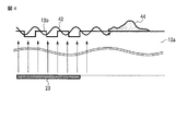
この圧電振動子23により発生された超音波振動は、図4に示すように主として当該圧電振動子23の貼着面に垂直な方向に伝播し、当該圧電振動子23に対向して設けられた回折格子13bに入射する。この回折格子13bに入射した超音波振動は、回折格子13bにより透明部材13aの外表面を伝播する弾性表面波43に変換される。この弾性表面波43は、透明部材13a上に付着している汚れ等44に到達すると、この汚れ等44を除去する。
A
The ultrasonic vibration generated by the
回折格子13bの格子周期λは、透明部材13aを伝播する弾性表面波43の速度v、超音波振動の周波数fとした場合、
λ=v/f
から算出される。
なお、上記図1乃至図3はそれぞれ説明しやすいように概略的に示しており、これら図上における寸法比は無視している。
When the grating period λ of the
λ = v / f
Is calculated from
1 to 3 are schematically shown for easy explanation, and the dimensional ratios in these drawings are ignored.
図5は内視鏡装置の機能ブロック図を示す。ビデオプロセッサ6には、制御部31が搭載されている。この制御部31には、画像処理部40と、撮像ドライバ41と、記憶部30と、信号発生部(電気エネルギー発生部)27と、判定部29とが接続されている。制御部31は、画像処理部40と、撮像ドライバ41と、信号発生部27と、判定部29とを動作制御し、かつ記憶部30への情報の書き込み、読み出しを行う。又、ビデオプロセッサ6には、電源部42が設けられている。ビデオプロセッサ6には、モニタ7が接続されている。
FIG. 5 shows a functional block diagram of the endoscope apparatus. A
一方、挿入部3には、透明部材13aと、観察光学系19と、撮像ユニット17と、圧電振動子23と、ライトガイドユニット22と、送水管路52とが設けられている。撮像ユニット17は、撮像素子11を備える。この撮像ユニット17は、信号ケーブル21を介してビデオプロセッサ6の撮像ドライバ41と画像処理部40とに接続されている。又、撮像ユニット17は、電源ケーブル51を介してビデオプロセッサ6の電源部42に接続されている。圧電振動子23は、通電ケーブル50を介してビデオプロセッサ6の検出部28に接続されている。通電ケーブル50は、圧電振動子23を駆動するための交流電力を圧電振動子23に供給し、かつ圧電振動子50からの反射電気エネルギーとしての反射電力を送る経路となる。ライトガイドユニット22は、光源装置5に接続されている。送水管路52には、送気/送水装置53が設けられている。
On the other hand, the
具体的に、撮像ドライバ41は、信号ケーブル21を通して駆動信号を撮像ユニット17に送る。この撮像ユニット17の撮像素子11は、撮像ドライバ41からの駆動信号を受けて例えば体腔内等の部位を撮像してその画像信号を出力する。撮像素子11から出力された画像信号は、信号ケーブル21を通して画像処理部40に送られる。この画像処理部40は、撮像素子11から伝送されてきた画像信号を処理して観察画像信号を生成し、この観察画像をモニタ7の表示画面7aに表示する。光源装置5は、内視鏡1により被検体の画像を撮像するための照明光をライトガイドユニット22に送る。ライトガイドユニット22は、光源装置5からの照明光を例えば体腔内等の部位の被検体に照射する。送気/送水装置53は、挿入部3の送水管路52に気体を送風すると共に、送水を行う。
Specifically, the
信号発生部27は、圧電振動子23を駆動して超音波振動を発生するための電気エネルギーとして交流電力を圧電振動子23に供給する。この信号発生部27は、交流電力を発生する。この信号発生部27により発生した交流電力は、検出部28、通電ケーブル50を通して圧電振動子23に供給される。
検出部28は、圧電振動子23に供給した交流電力のうち圧電振動子23と通電ケーブル50とを含む供給系から反射された電気エネルギーとしての反射電力を当該反射電力に応じた直流電力として抽出する。
The
The
図6は検出部28の回路構成図を示す。第1のポート38は、信号発生部27に接続されている。この第1のポート38と第2のポート39との間には、結合回路60が接続されている。この結合回路60は、信号発生部27から出力された交流電力を通電ケーブル50を通して圧電振動子23に加え、この圧電振動子23から反射される交流の反射電力を抽出する。
FIG. 6 shows a circuit configuration diagram of the
具体的に結合回路60は、複数のインダクタ32a、32b、32c、32dと、複数のキャパシタ33a、33b、34a、34bと、抵抗37とからなる。2つのインダクタ32a、32bは、第1のポート38と第2のポート39との間に直列接続されている。2つのインダクタ32c、32dが直列接続され、かつこれらインダクタ32c、32dの直列回路の両端がそれぞれキャパシタ34a、34bを介して2つのインダクタ32a、32bの直列回路の両端に接続されている。又、インダクタ32a、32bの直列回路の間にキャパシタ33aが接続されている。2つのインダクタ32c、32dの直列回路の間にキャパシタ33bが接続されている。2つのダイオード36a、36bがキャパシタ34aとインダクタ32aとの間にそれぞれ順方向、逆方向で接続されている。これらダイオード36a、36bは、それぞれ判定部29に接続されている。又、ダイオード36a、36bは、それぞれ各キャパシタ35a、35bが並列接続されている。
Specifically, the
なお、結合回路60は、圧電振動子23からの反射電力をより効率的に抽出するために、各ダイオード36a、36bとキャパシタ34aとの間又はダイオード36a、36bとインダクタ32cとの間にグランドに接地されたインダクタを接続してもよい。同様に、結合回路60は、ダイオード36aとキャパシタ35aとの間又はダイオード36bとキャパシタ35bとの間にグランドに接地された抵抗を接続してもよい。
The
このような構成であれば、信号発生部27から出力された交流電力は、検出部28の2つのインダクタ32a、32bを通過し、通電ケーブル50を通して圧電振動子23に加えられる。この圧電振動子23から反射される交流の反射電力は、通電ケーブル50を通して再び検出部28に到達する。この際、検出部28内にある複数のインダクタ32a、32b、32c、32dと、複数のキャパシタ33a、33b、34a、34bと、抵抗37とからなるインピーダンス素子の結合効果によって反射電力を検出することができる。すなわち、圧電振動子23から反射される反射電力は、複数のキャパシタ34a、34bを通して2つのダイオード36a、36bと各キャパシタ35a、35bとに送られる。これらダイオード36a、36bと各キャパシタ35a、35bとにより交流の反射電力は、交流の平均電力に応じた電圧値に変換される。この交流の平均電力に応じた電圧値は、判定部29に送られる。
With such a configuration, the AC power output from the
判定部29は、検出部28により検出された圧電振動子23から反射される反射電力に応じた交流の平均電力に応じた電圧値に基づいて圧電振動子23を適切に駆動するための交流電力が圧電振動子23に供給されているか否かを判定する。具体的に判定部29は、検出部28により検出された交流の平均電力に応じた電圧値と予め設定された閾値とを比較し、交流の平均電力に応じた電圧値が閾値以上であるか否かを判定する。
The
記憶部30には、判定部29の判定結果として例えば信号発生部27から出力される交流電力量の増減の量や、信号発生部27からの交流電力の出力の停止の履歴が記憶される。又、記憶部30には、判定部29において検出部28により検出された交流の平均電力に応じた電圧値と比較するための閾値が予め記憶されている。さらに、記憶部30には、本装置の動作制御プログラムが記憶されている。
The
この動作制御プログラムは、信号発生部27から交流電力を発生させて、圧電振動子23に供給した交流電力のうち圧電振動子23と当該圧電振動子23に交流電力を供給する通電ケーブル50とを含むエネルギ供給系から反射された反射電力を検出部28により検出させる検出機能と、検出された反射電力に基づいて圧電振動子23を適切に駆動するための交流電力が圧電振動子23に供給されているか否かを判定させる判定機能と、この判定結果に基づいて信号発生部27から出力される交流電力を制御する制御機能とを有する。
This operation control program generates AC power from the
判定機能は、反射電力と予め設定された閾値とを比較する。
制御機能は、判定機能による判定の結果、反射電力が閾値以上であると判定すると、圧電振動子23又は通電ケーブル50のいずれか一方又は両方に予期しない事態が発生したとして信号発生部27からの交流電力の出力を停止する。
The determination function compares the reflected power with a preset threshold value.
If the control function determines that the reflected power is greater than or equal to the threshold value as a result of the determination by the determination function, it is determined that an unexpected situation has occurred in either one or both of the
制御部31は、記憶部30に記憶されている動作制御プログラムを実行して画像処理部40と、撮像ドライバ41と、信号発生部27と、判定部29とを動作制御する。
制御部31は、判定部29の判定結果に基づいて信号発生部27から出力される交流電力量を増減して制御する。又、制御部31は、判定部29により交流の平均電力に応じた電圧値が閾値以上であると判定すると、圧電振動子23又は通電ケーブル50のいずれか一方又は両方に予期しない事態、例えば通電ケーブル50のオープン、ショート等が発生したとして信号発生部27からの交流電力の出力を停止する。
制御部31は、信号発生部27からの交流電力の出力を停止すると、当該信号発生部27からの交流電力の出力停止の旨をモニタ7に表示する。
制御部31は、少なくとも判定部29の判定結果、例えば信号発生部27から出力される交流電力量の増減の量、信号発生部27からの交流電力の出力の停止の履歴を記憶部30に記録する。
The
The
When the
The
次に、上記の如く構成された装置の動作について図7に示す動作制御フローチャートに従って説明する。
制御部31は、ステップS1において、信号発生部27に交流電力の出力指令を出力する。信号発生部27は、制御部31からの出力指令を受けて、圧電振動子23を駆動して超音波振動を発生するための交流電力を圧電振動子23に供給する。この信号発生部27は、交流電力を発生する。
Next, the operation of the apparatus configured as described above will be described according to the operation control flowchart shown in FIG.
In step S <b> 1, the
この信号発生部27により発生した交流電力は、図6に示す検出部28の2つのインダクタ32a、32bを通過し、通電ケーブル50を通して圧電振動子23に加えられる。この圧電振動子23からは、交流の反射電力が生じ、この反射電力は、通電ケーブル50を通して再び検出部28に到達する。この検出部28では、複数のインダクタ32a、32b、32c、32dと、複数のキャパシタ33a、33b、34a、34bと、抵抗37とからなるインピーダンス素子の結合効果によって反射電力を検出する。すなわち、圧電振動子23から反射される反射電力は、複数のキャパシタ34a、34bを通して2つのダイオード36a、36bと各キャパシタ35a、35bとに送られる。これらダイオード36a、36bと各キャパシタ35a、35bとにより交流の反射電力は、交流の平均電力に応じた電圧値に変換される。この交流の平均電力に応じた電圧値は、判定部29に送られる。
The AC power generated by the
この判定部29は、ステップS2において、検出部28により検出された交流の平均電力に応じた電圧値と予め設定された閾値とを比較し、交流の平均電力に応じた電圧値が閾値以上であるか否かを判定する。この比較の結果、交流の平均電力に応じた電圧値が閾値以下であれば、判定部29は、その旨を制御部31に送る。
この制御部31は、ステップS3において、圧電振動子23を適切に駆動するための交流電力が圧電振動子23に供給されているという正常な旨をモニタ7に表示する。又、判定部29は、交流の平均電力に応じた電圧値に対応した電力情報を制御部31に送る。この制御部31は、判定部29からの電力情報に応じて信号発生部27から出力される交流電力量を増減して制御する。
In step S2, the
In step S <b> 3, the
制御部31は、ステップS4において、例えば操作部2等から手動操作により停止の旨を受けたか否かを判断する。この判断の結果、停止の旨を受けていなければ、制御部31は、再びステップS2に戻る。停止の旨を受けると、制御部31は、ステップS5に移り、信号発生部27からの交流電力の発生を停止し、本装置の動作を終了する。
In step S4, for example, the
ところで、圧電振動子23は、例えば、使用を重ねるうちに元の性質を損なってしまう場合がある。このような場合、圧電振動子23のインピーダンスが変化するために、インピーダンスの不整合が生じ、圧電振動子23からの反射電力量が大きくなる。このように圧電振動子23からの反射電力量が大きくなると、検出部28により検出された交流の平均電力に応じた電圧値は、閾値を上回り、閾値以上になる。
By the way, the
この場合、判定部29は、ステップS2において、検出部28により検出された交流の平均電力に応じた電圧値が閾値以上であると判定し、この旨を制御部31に送る。
この制御部31は、ステップS2からステップS6に移り、信号発生部27からの交流電力の出力を停止する。
制御部31は、ステップS7において、信号発生部27からの交流電力の出力を停止した異常の旨をモニタ7に表示する。
In this case, in step S <b> 2, the
The
In step S <b> 7, the
又、圧電振動子23へ電力を供給する経路、すなわち通電ケーブル50に予期しない事態、例えば経路オープン、ショート等が生じた場合がある。この場合も反射電力は大きくなる。このように反射電力量が大きくなると、検出部28により検出された交流の平均電力に応じた電圧値は、閾値以上になる。この場合も、判定部29は、ステップS2において、検出部28により検出された交流の平均電力に応じた電圧値が閾値以上であると判定し、この旨を制御部31に送る。
この制御部31は、ステップS2からステップS6に移り、信号発生部27からの交流電力の出力を停止する。
制御部31は、ステップS7において、信号発生部27からの交流電力の出力を停止した異常の旨をモニタ7に表示する。
In addition, an unexpected situation such as a path open or a short circuit may occur in the path for supplying power to the
The
In step S <b> 7, the
なお、制御部31は、信号発生部27からの交流電力の出力を停止した理由として、圧電振動子23が使用を重ねるうちに元の性質を損なったこと、通電ケーブル50に予期しない事態、例えば経路オープン、ショート等が生じたことである旨をモニタ7に表示してもよい。
The
このように上記一実施の形態によれば、圧電振動子23と当該圧電振動子23に交流電力を供給する通電ケーブル50とから反射された反射電力を検出し、この反射電力に基づいて圧電振動子23を適切に駆動するための交流電力が圧電振動子23に供給されているか否かを判定し、この判定結果に基づいて信号発生部27から出力される交流電力を制御する。例えば、反射電力が閾値以上であると判定すると、圧電振動子23又は通電ケーブル50のいずれか一方又は両方に予期しない事態が発生したとして信号発生部27からの交流電力の出力を停止する。
As described above, according to the above-described embodiment, the reflected power reflected from the
これにより、圧電振動子23の駆動状態をモニタリングすることにより、圧電振動子23を適切に駆動できると共に、通電ケーブル50を含む経路上の不具合要因を早期に検出して安全性を向上できる。すなわち、圧電振動子23が使用を重ねるうちに元の性質を損なったか、又は通電ケーブル50に予期しない事態、例えば経路オープン、ショート等が生じたかのいずれか一方又は両方であることがモニタ7上の表示から分る。具体的に圧電振動子23に大電力を供給するための通電ケーブル50を含む経路上に不測の不具合、例えば断線、短絡、圧電振動子23の損傷等が発生した場合を早期に検出してその対処がいち早くできる。
Thereby, by monitoring the driving state of the
なお、本発明は上記実施形態そのままに限定されるものではなく、実施段階ではその要旨を逸脱しない範囲で構成要素を変形して具体化できる。また、上記実施形態に開示されている複数の構成要素の適宜な組み合わせにより、種々の発明を形成できる。例えば、実施形態に示される全構成要素から幾つかの構成要素を削除してもよい。さらに、異なる実施形態にわたる構成要素を適宜組み合わせてもよい。
例えば、本装置のように圧電振動子23と当該圧電振動子23に交流電力を供給する通電ケーブル50とから反射された反射電力を検出し、この反射電力に基づいて圧電振動子23を適切に駆動するための交流電力が圧電振動子23に供給されているか否かを判定し、この判定結果に基づいて信号発生部27から出力される交流電力を制御することは、本装置の電源投入後で、かつ本装置の挿入部3を例えば体腔内等の被検体内に挿入して使用する前に行うようにしてもよい。
Note that the present invention is not limited to the above-described embodiment as it is, and can be embodied by modifying the constituent elements without departing from the scope of the invention in the implementation stage. In addition, various inventions can be formed by appropriately combining a plurality of components disclosed in the embodiment. For example, some components may be deleted from all the components shown in the embodiment. Furthermore, constituent elements over different embodiments may be appropriately combined.
For example, the reflected power reflected from the
1:内視鏡、2:操作部、3:挿入部、3a:ユニバーサルコード、4:コネクタ部、5:光源装置、6:ビデオプロセッサ、7:モニタ、7a:表示画面、8:チューブ、9:湾曲部、10:先端部、11:撮像素子、12:先端面、13:観察窓、13a:透明部材、13b:回折格子、14a,14b,14c:照明窓、15:処置具等開口部、16:送水ノズル、16a:連結管、16b:送水チューブ、17:撮像ユニット、18:先端硬質部、19:観察光学系、20:基板、21:信号ケーブル、22:ライトガイドユニット、22a:照明用レンズ、22b:光ファイバ束、22c:金属パイプ、23:圧電振動子、25:外皮チューブ、26:キャップ、27:信号発生部(電気エネルギー発生部)、28:検出部、29:判定部、30:記憶部、31:制御部、32a,32b,32c,32d:インダクタ、33a,33b,34a,34b:キャパシタ、36a,36b:ダイオード、37:抵抗、38:第1のポート、39:第2のポート、40:画像処理部、41:撮像ドライバ、42:電源部、43:弾性表面波、44:汚れ等、50:通電ケーブル、51:電源ケーブル、52:送水管路、60:結合回路。 1: Endoscope, 2: Operation part, 3: Insertion part, 3a: Universal code, 4: Connector part, 5: Light source device, 6: Video processor, 7: Monitor, 7a: Display screen, 8: Tube, 9 : Bending portion, 10: tip portion, 11: imaging element, 12: tip surface, 13: observation window, 13a: transparent member, 13b: diffraction grating, 14a, 14b, 14c: illumination window, 15: opening for treatment instrument, etc. 16: Water supply nozzle, 16a: Connecting pipe, 16b: Water supply tube, 17: Imaging unit, 18: Hard tip, 19: Observation optical system, 20: Substrate, 21: Signal cable, 22: Light guide unit, 22a: Illumination lens, 22b: optical fiber bundle, 22c: metal pipe, 23: piezoelectric vibrator, 25: outer tube, 26: cap, 27: signal generator (electric energy generator), 28: detector, 29 Determination unit, 30: storage unit, 31: control unit, 32a, 32b, 32c, 32d: inductor, 33a, 33b, 34a, 34b: capacitor, 36a, 36b: diode, 37: resistor, 38: first port, 39: second port, 40: image processing unit, 41: imaging driver, 42: power supply unit, 43: surface acoustic wave, 44: dirt, 50: energizing cable, 51: power cable, 52: water supply conduit, 60: A coupling circuit.
Claims (13)
前記透明部材に設けられ、超音波振動を発生する超音波振動子と、
前記超音波振動子を駆動して前記超音波振動を発生するための電気エネルギーを供給する電気エネルギー発生部と、
前記透明部材に設けられ、前記超音波振動素子により発生した前記超音波振動を前記透明部材に与えて当該透明部材の表面を伝播する弾性表面波に変換する回折格子と、
前記超音波振動子に供給した前記電気エネルギーのうち前記超音波振動子と前記超音波振動子に前記電気エネルギーを供給する経路とを含む供給系から反射された反射電気エネルギーを検出する検出部と、
前記検出部により検出された前記反射電気エネルギーに基づいて前記超音波振動子を適切に駆動するための前記電気エネルギーが前記超音波振動子に供給されているか否かを判定する判定部と、
前記判定部の判定結果に基づいて前記電気エネルギー発生部から出力される前記電気エネルギーを制御する制御部と、
を具備することを特徴とする内視鏡装置。 A transparent member provided at the tip,
An ultrasonic vibrator provided on the transparent member and generating ultrasonic vibration;
An electric energy generator for supplying electric energy for driving the ultrasonic vibrator to generate the ultrasonic vibration;
A diffraction grating that is provided on the transparent member and converts the ultrasonic vibration generated by the ultrasonic vibration element into a surface acoustic wave that propagates through the surface of the transparent member by applying the ultrasonic vibration to the transparent member;
A detection unit for detecting reflected electric energy reflected from a supply system including the ultrasonic vibrator and a path for supplying the electric energy to the ultrasonic vibrator among the electric energy supplied to the ultrasonic vibrator; ,
A determination unit that determines whether or not the electric energy for appropriately driving the ultrasonic transducer based on the reflected electric energy detected by the detection unit is supplied to the ultrasonic transducer;
A control unit that controls the electrical energy output from the electrical energy generation unit based on a determination result of the determination unit;
An endoscope apparatus comprising:
前記制御部は、前記判定部の比較結果に応じて前記電気エネルギー発生部から出力される前記電気エネルギー値を増減させることを特徴とする請求項2記載の内視鏡装置。 The determination unit compares the reflected electric energy value detected by the detection unit with a preset threshold value,
The endoscope apparatus according to claim 2, wherein the control unit increases or decreases the electric energy value output from the electric energy generation unit according to a comparison result of the determination unit.
前記制御部は、前記判定部の比較結果、前記反射電気エネルギーが前記閾値以上であれば、前記電気エネルギー発生部からの前記電気エネルギーの出力を停止する、
ことを特徴とする請求項2記載の内視鏡装置。 The determination unit compares the reflected electric energy value detected by the detection unit with a preset threshold value,
The control unit stops the output of the electric energy from the electric energy generation unit if the reflected electric energy is equal to or greater than the threshold value as a result of the determination by the determination unit.
The endoscope apparatus according to claim 2.
前記制御部は、前記電気エネルギー発生部からの前記電気エネルギーの出力停止の旨を前記モニタに表示することを特徴とする請求項4記載の内視鏡装置。 Have a monitor,
The endoscope apparatus according to claim 4, wherein the control unit displays on the monitor that the output of the electric energy from the electric energy generation unit is stopped.
前記判定部は、前記検出部により検出された前記反射電気エネルギー値と予め設定された閾値とを比較し、
前記制御部は、前記判定部により前記反射電気エネルギー値が前記閾値以上であると判定すると、前記超音波振動子又は前記ケーブルのいずれか一方又は両方に予期しない事態が発生したとして前記電気エネルギー発生部からの前記電気エネルギーの出力を停止する、
ことを特徴とする請求項1記載の内視鏡装置。 Sending the electrical energy generated by the electrical energy generator to the ultrasonic transducer, and having a cable as the path for sending the reflected electrical energy from the ultrasonic transducer,
The determination unit compares the reflected electric energy value detected by the detection unit with a preset threshold value,
When the control unit determines that the reflected electric energy value is equal to or greater than the threshold value, the control unit determines that an unexpected situation has occurred in either one or both of the ultrasonic transducer and the cable. Stop the output of the electrical energy from the part,
The endoscope apparatus according to claim 1.
検出部が前記超音波振動子に供給した前記電気エネルギーのうち前記超音波振動子と前記超音波振動子に前記電気エネルギーを供給する経路とを含むエネルギー供給系から反射された反射電気エネルギーを検出し、
判定部が前記検出部により検出された前記反射電気エネルギーに基づいて前記圧電振動子を適切に駆動するための前記電気エネルギーが前記超音波振動子に供給されているか否かを判定し、
制御部が前記判定部の判定結果に基づいて前記電気エネルギー発生部から出力される前記電気エネルギーを制御する、
ことを特徴とする内視鏡装置の動作制御方法。 The ultrasonic vibrator provided on the transparent member at the tip is supplied with electric energy from the electric energy generator to generate ultrasonic vibration, and this ultrasonic vibration is applied to the transparent member to be provided on the transparent member. In the operation control method of the endoscope apparatus that converts the surface acoustic wave to propagate through the surface of the transparent member by the diffraction grating,
Detecting the reflected electrical energy reflected from the energy supply system comprising a path for supplying the electrical energy to the ultrasonic transducer and the ultrasonic transducer of the electrical energy detecting portion is supplied to the ultrasonic vibrator And
Determination unit determines whether or not the electrical energy to adequately drive the piezoelectric vibrator on the basis of the detected reflected electrical energy is supplied to the ultrasonic vibrator by the detecting unit,
Control unit controls the electrical energy output from said electric energy generating unit based on a determination result of the determination unit,
An operation control method for an endoscope apparatus characterized by the above.
前記制御部が行う制御では、前記反射電気エネルギー値が前記閾値以上であると判定すると、前記超音波振動子又は前記ケーブルのいずれか一方又は両方に予期しない事態が発生したとして前記電気エネルギー発生部からの前記電気エネルギーの出力を停止する、
ことを特徴とする請求項12記載の内視鏡装置の動作制御方法。 In the determination performed by the determination unit, the reflected electric energy value is compared with a preset threshold value,
In the control performed by the control unit , if it is determined that the reflected electric energy value is equal to or greater than the threshold value, it is determined that an unexpected situation has occurred in either one or both of the ultrasonic transducer and the cable. Stop the output of the electrical energy from,
The operation control method for an endoscope apparatus according to claim 12.
Priority Applications (5)
| Application Number | Priority Date | Filing Date | Title |
|---|---|---|---|
| JP2010222840A JP5752910B2 (en) | 2010-09-30 | 2010-09-30 | Endoscope apparatus and operation control method thereof |
| PCT/JP2011/071873 WO2012043468A1 (en) | 2010-09-30 | 2011-09-26 | Endoscope device and method for controlling operation thereof |
| EP11829022.0A EP2623015B1 (en) | 2010-09-30 | 2011-09-26 | Endoscope device and method for controlling operation thereof |
| CN201180046073.9A CN103153153B (en) | 2010-09-30 | 2011-09-26 | Endoscope apparatus and method of controlling operation thereof |
| US13/801,760 US9226647B2 (en) | 2010-09-30 | 2013-03-13 | Endoscopic apparatus and operation control method for the same |
Applications Claiming Priority (1)
| Application Number | Priority Date | Filing Date | Title |
|---|---|---|---|
| JP2010222840A JP5752910B2 (en) | 2010-09-30 | 2010-09-30 | Endoscope apparatus and operation control method thereof |
Publications (2)
| Publication Number | Publication Date |
|---|---|
| JP2012075615A JP2012075615A (en) | 2012-04-19 |
| JP5752910B2 true JP5752910B2 (en) | 2015-07-22 |
Family
ID=45892912
Family Applications (1)
| Application Number | Title | Priority Date | Filing Date |
|---|---|---|---|
| JP2010222840A Active JP5752910B2 (en) | 2010-09-30 | 2010-09-30 | Endoscope apparatus and operation control method thereof |
Country Status (5)
| Country | Link |
|---|---|
| US (1) | US9226647B2 (en) |
| EP (1) | EP2623015B1 (en) |
| JP (1) | JP5752910B2 (en) |
| CN (1) | CN103153153B (en) |
| WO (1) | WO2012043468A1 (en) |
Families Citing this family (9)
| Publication number | Priority date | Publication date | Assignee | Title |
|---|---|---|---|---|
| FR3015698B1 (en) * | 2013-12-20 | 2022-10-14 | Turbomeca | ENDOSCOPE AND METHOD FOR ITS USE |
| DE102014214754A1 (en) | 2014-07-28 | 2016-01-28 | Digital Endoscopy Gmbh | Endoscopic device |
| US10987129B2 (en) | 2015-09-04 | 2021-04-27 | Medos International Sarl | Multi-shield spinal access system |
| US11439380B2 (en) | 2015-09-04 | 2022-09-13 | Medos International Sarl | Surgical instrument connectors and related methods |
| US11744447B2 (en) | 2015-09-04 | 2023-09-05 | Medos International | Surgical visualization systems and related methods |
| US11672562B2 (en) | 2015-09-04 | 2023-06-13 | Medos International Sarl | Multi-shield spinal access system |
| CN113143355A (en) | 2015-09-04 | 2021-07-23 | 美多斯国际有限公司 | Multi-shield spinal access system |
| WO2017138211A1 (en) * | 2016-02-12 | 2017-08-17 | オリンパス株式会社 | Scanning endoscope system |
| WO2018193519A1 (en) * | 2017-04-18 | 2018-10-25 | オリンパス株式会社 | Endoscope device and video processor |
Family Cites Families (12)
| Publication number | Priority date | Publication date | Assignee | Title |
|---|---|---|---|---|
| US4870950A (en) * | 1987-07-08 | 1989-10-03 | Kouji Kanbara | Endoscope system |
| US4924852A (en) * | 1987-09-11 | 1990-05-15 | Olympus Optical Co., Ltd. | Endoscope |
| JP2598474B2 (en) * | 1987-12-09 | 1997-04-09 | オリンパス光学工業株式会社 | Ultrasonic suction device |
| JPH071130Y2 (en) * | 1988-10-25 | 1995-01-18 | オリンパス光学工業株式会社 | Ultrasonic treatment device |
| JP3217386B2 (en) * | 1991-04-24 | 2001-10-09 | オリンパス光学工業株式会社 | Diagnostic system |
| JP4046778B2 (en) * | 1995-04-05 | 2008-02-13 | ソニー株式会社 | Optical disk recording / reproducing device |
| WO2005082226A1 (en) * | 2004-02-27 | 2005-09-09 | Olympus Corporation | Endoscope |
| JP5041657B2 (en) * | 2004-08-18 | 2012-10-03 | オリンパス株式会社 | Endoscope device |
| US20080188714A1 (en) * | 2007-02-07 | 2008-08-07 | Boston Scientific Scimed, Inc. | Electromechanical in-situ cleaning of optical elements |
| US9050036B2 (en) * | 2007-06-19 | 2015-06-09 | Minimally Invasive Devices, Inc. | Device for maintaining visualization with surgical scopes |
| JP5129004B2 (en) * | 2008-04-16 | 2013-01-23 | オリンパス株式会社 | Endoscope device |
| JP5330180B2 (en) * | 2009-10-02 | 2013-10-30 | オリンパス株式会社 | Endoscope device |
-
2010
- 2010-09-30 JP JP2010222840A patent/JP5752910B2/en active Active
-
2011
- 2011-09-26 WO PCT/JP2011/071873 patent/WO2012043468A1/en active Application Filing
- 2011-09-26 CN CN201180046073.9A patent/CN103153153B/en not_active Expired - Fee Related
- 2011-09-26 EP EP11829022.0A patent/EP2623015B1/en not_active Not-in-force
-
2013
- 2013-03-13 US US13/801,760 patent/US9226647B2/en active Active
Also Published As
| Publication number | Publication date |
|---|---|
| EP2623015A4 (en) | 2015-04-15 |
| US20130197308A1 (en) | 2013-08-01 |
| EP2623015B1 (en) | 2017-01-11 |
| JP2012075615A (en) | 2012-04-19 |
| CN103153153A (en) | 2013-06-12 |
| EP2623015A1 (en) | 2013-08-07 |
| US9226647B2 (en) | 2016-01-05 |
| CN103153153B (en) | 2015-11-25 |
| WO2012043468A1 (en) | 2012-04-05 |
Similar Documents
| Publication | Publication Date | Title |
|---|---|---|
| JP5752910B2 (en) | Endoscope apparatus and operation control method thereof | |
| JP6450892B1 (en) | Endoscope | |
| JP6170240B2 (en) | Ultrasound endoscope | |
| US20080188714A1 (en) | Electromechanical in-situ cleaning of optical elements | |
| JP2598474B2 (en) | Ultrasonic suction device | |
| JP2009254571A (en) | Endoscope apparatus | |
| JP6672200B2 (en) | Endoscope | |
| JP6625746B2 (en) | Ultrasound endoscope and method of manufacturing the same | |
| JP2010022758A (en) | Endoscope device | |
| JP2012000338A (en) | Endoscope apparatus | |
| JP2009189496A (en) | Endoscope apparatus, and control method thereof for removing dirt and haziness attached to observation window surface of endoscope | |
| JP5826551B2 (en) | Endoscope device | |
| JP5399305B2 (en) | Imaging apparatus and endoscope | |
| WO2014057773A1 (en) | Endoscope device and treatment device | |
| JP6677799B2 (en) | Ultrasonic transducer unit | |
| JP6633189B2 (en) | Ultrasonic transducer unit | |
| JP2006280407A (en) | Ultrasonic endoscope | |
| JP2013048693A (en) | Endoscope device | |
| JP6830913B2 (en) | Ultrasound endoscope and endoscope device | |
| JP2012213483A (en) | Endoscope apparatus | |
| WO2013021780A1 (en) | Endoscopic apparatus | |
| JPH03106331A (en) | Curve detecting device for endoscope | |
| CN112469322A (en) | Connector for endoscope and endoscope | |
| JP2710419B2 (en) | Endoscope device | |
| JP3181937U (en) | Ultrasonic endoscope ultrasonic connector |
Legal Events
| Date | Code | Title | Description |
|---|---|---|---|
| A621 | Written request for application examination |
Free format text: JAPANESE INTERMEDIATE CODE: A621 Effective date: 20130808 |
|
| A131 | Notification of reasons for refusal |
Free format text: JAPANESE INTERMEDIATE CODE: A131 Effective date: 20140930 |
|
| A521 | Request for written amendment filed |
Free format text: JAPANESE INTERMEDIATE CODE: A523 Effective date: 20141022 |
|
| A131 | Notification of reasons for refusal |
Free format text: JAPANESE INTERMEDIATE CODE: A131 Effective date: 20141125 |
|
| A521 | Request for written amendment filed |
Free format text: JAPANESE INTERMEDIATE CODE: A523 Effective date: 20141212 |
|
| TRDD | Decision of grant or rejection written | ||
| A01 | Written decision to grant a patent or to grant a registration (utility model) |
Free format text: JAPANESE INTERMEDIATE CODE: A01 Effective date: 20150428 |
|
| A61 | First payment of annual fees (during grant procedure) |
Free format text: JAPANESE INTERMEDIATE CODE: A61 Effective date: 20150521 |
|
| R151 | Written notification of patent or utility model registration |
Ref document number: 5752910 Country of ref document: JP Free format text: JAPANESE INTERMEDIATE CODE: R151 |
|
| S531 | Written request for registration of change of domicile |
Free format text: JAPANESE INTERMEDIATE CODE: R313531 |
|
| R350 | Written notification of registration of transfer |
Free format text: JAPANESE INTERMEDIATE CODE: R350 |
|
| R250 | Receipt of annual fees |
Free format text: JAPANESE INTERMEDIATE CODE: R250 |
|
| R250 | Receipt of annual fees |
Free format text: JAPANESE INTERMEDIATE CODE: R250 |
|
| R250 | Receipt of annual fees |
Free format text: JAPANESE INTERMEDIATE CODE: R250 |
|
| R250 | Receipt of annual fees |
Free format text: JAPANESE INTERMEDIATE CODE: R250 |
|
| R250 | Receipt of annual fees |
Free format text: JAPANESE INTERMEDIATE CODE: R250 |