EP3448225B1 - Vision preservation system for medical devices - Google Patents
Vision preservation system for medical devices Download PDFInfo
- Publication number
- EP3448225B1 EP3448225B1 EP17722312.0A EP17722312A EP3448225B1 EP 3448225 B1 EP3448225 B1 EP 3448225B1 EP 17722312 A EP17722312 A EP 17722312A EP 3448225 B1 EP3448225 B1 EP 3448225B1
- Authority
- EP
- European Patent Office
- Prior art keywords
- lens
- cap
- endoscope
- purging fluid
- visualization system
- Prior art date
- Legal status (The legal status is an assumption and is not a legal conclusion. Google has not performed a legal analysis and makes no representation as to the accuracy of the status listed.)
- Active
Links
- 238000004321 preservation Methods 0.000 title description 3
- 239000012530 fluid Substances 0.000 claims description 210
- 238000010926 purge Methods 0.000 claims description 191
- 230000007246 mechanism Effects 0.000 claims description 97
- 238000012800 visualization Methods 0.000 claims description 60
- 239000007789 gas Substances 0.000 claims description 36
- IJGRMHOSHXDMSA-UHFFFAOYSA-N Atomic nitrogen Chemical compound N#N IJGRMHOSHXDMSA-UHFFFAOYSA-N 0.000 claims description 26
- 239000007788 liquid Substances 0.000 claims description 20
- 229910052757 nitrogen Inorganic materials 0.000 claims description 12
- 238000005192 partition Methods 0.000 claims description 11
- 239000012071 phase Substances 0.000 claims description 10
- CURLTUGMZLYLDI-UHFFFAOYSA-N Carbon dioxide Chemical compound O=C=O CURLTUGMZLYLDI-UHFFFAOYSA-N 0.000 claims description 9
- 229910002092 carbon dioxide Inorganic materials 0.000 claims description 5
- 239000001569 carbon dioxide Substances 0.000 claims description 5
- QVGXLLKOCUKJST-UHFFFAOYSA-N atomic oxygen Chemical compound [O] QVGXLLKOCUKJST-UHFFFAOYSA-N 0.000 claims description 4
- 239000007791 liquid phase Substances 0.000 claims description 4
- 239000001301 oxygen Substances 0.000 claims description 4
- 229910052760 oxygen Inorganic materials 0.000 claims description 4
- 239000003570 air Substances 0.000 claims description 3
- 238000004140 cleaning Methods 0.000 claims 1
- 238000010438 heat treatment Methods 0.000 description 42
- 238000002681 cryosurgery Methods 0.000 description 25
- 238000000034 method Methods 0.000 description 20
- 230000007704 transition Effects 0.000 description 15
- 239000000463 material Substances 0.000 description 13
- 238000009833 condensation Methods 0.000 description 12
- 230000005494 condensation Effects 0.000 description 12
- 230000000694 effects Effects 0.000 description 12
- 238000000315 cryotherapy Methods 0.000 description 9
- 238000003780 insertion Methods 0.000 description 9
- 230000037431 insertion Effects 0.000 description 9
- 239000007921 spray Substances 0.000 description 9
- 229920002614 Polyether block amide Polymers 0.000 description 8
- 239000004033 plastic Substances 0.000 description 8
- 229920003023 plastic Polymers 0.000 description 8
- 238000001125 extrusion Methods 0.000 description 6
- 238000009413 insulation Methods 0.000 description 6
- 239000004094 surface-active agent Substances 0.000 description 6
- 230000000903 blocking effect Effects 0.000 description 5
- 210000001124 body fluid Anatomy 0.000 description 5
- 239000011248 coating agent Substances 0.000 description 5
- 238000000576 coating method Methods 0.000 description 5
- 238000010276 construction Methods 0.000 description 5
- 229910001220 stainless steel Inorganic materials 0.000 description 5
- 239000010935 stainless steel Substances 0.000 description 5
- 238000011282 treatment Methods 0.000 description 5
- 230000006870 function Effects 0.000 description 4
- 239000002184 metal Substances 0.000 description 4
- 239000002245 particle Substances 0.000 description 4
- 230000008569 process Effects 0.000 description 4
- 239000000523 sample Substances 0.000 description 4
- 210000001519 tissue Anatomy 0.000 description 4
- 238000013022 venting Methods 0.000 description 4
- 230000004888 barrier function Effects 0.000 description 3
- 230000008901 benefit Effects 0.000 description 3
- 238000004891 communication Methods 0.000 description 3
- 229920001971 elastomer Polymers 0.000 description 3
- 238000005516 engineering process Methods 0.000 description 3
- 238000007710 freezing Methods 0.000 description 3
- 230000008014 freezing Effects 0.000 description 3
- 210000003097 mucus Anatomy 0.000 description 3
- 230000001151 other effect Effects 0.000 description 3
- 230000005855 radiation Effects 0.000 description 3
- 238000007789 sealing Methods 0.000 description 3
- 238000010792 warming Methods 0.000 description 3
- 239000004642 Polyimide Substances 0.000 description 2
- 239000004820 Pressure-sensitive adhesive Substances 0.000 description 2
- 239000000853 adhesive Substances 0.000 description 2
- 239000006117 anti-reflective coating Substances 0.000 description 2
- 210000000621 bronchi Anatomy 0.000 description 2
- 230000032798 delamination Effects 0.000 description 2
- 238000013461 design Methods 0.000 description 2
- 230000009977 dual effect Effects 0.000 description 2
- 239000000835 fiber Substances 0.000 description 2
- 230000002209 hydrophobic effect Effects 0.000 description 2
- 238000003384 imaging method Methods 0.000 description 2
- 239000012212 insulator Substances 0.000 description 2
- 230000003287 optical effect Effects 0.000 description 2
- 229920000139 polyethylene terephthalate Polymers 0.000 description 2
- 239000005020 polyethylene terephthalate Substances 0.000 description 2
- 229920001721 polyimide Polymers 0.000 description 2
- 229920000642 polymer Polymers 0.000 description 2
- 239000002861 polymer material Substances 0.000 description 2
- 238000000926 separation method Methods 0.000 description 2
- 229920002725 thermoplastic elastomer Polymers 0.000 description 2
- 239000012780 transparent material Substances 0.000 description 2
- 229920004142 LEXAN™ Polymers 0.000 description 1
- 239000004418 Lexan Substances 0.000 description 1
- 229920001410 Microfiber Polymers 0.000 description 1
- 239000004677 Nylon Substances 0.000 description 1
- 229910000831 Steel Inorganic materials 0.000 description 1
- 206010047571 Visual impairment Diseases 0.000 description 1
- 208000027418 Wounds and injury Diseases 0.000 description 1
- 238000002679 ablation Methods 0.000 description 1
- 238000009825 accumulation Methods 0.000 description 1
- 230000001070 adhesive effect Effects 0.000 description 1
- 230000033228 biological regulation Effects 0.000 description 1
- 230000036760 body temperature Effects 0.000 description 1
- 239000005388 borosilicate glass Substances 0.000 description 1
- 238000013276 bronchoscopy Methods 0.000 description 1
- 239000002775 capsule Substances 0.000 description 1
- 230000008859 change Effects 0.000 description 1
- 238000006243 chemical reaction Methods 0.000 description 1
- 230000001010 compromised effect Effects 0.000 description 1
- 239000000356 contaminant Substances 0.000 description 1
- 238000001816 cooling Methods 0.000 description 1
- 238000013480 data collection Methods 0.000 description 1
- 230000001419 dependent effect Effects 0.000 description 1
- 238000002405 diagnostic procedure Methods 0.000 description 1
- 230000003467 diminishing effect Effects 0.000 description 1
- 229910001873 dinitrogen Inorganic materials 0.000 description 1
- 239000003814 drug Substances 0.000 description 1
- 230000008030 elimination Effects 0.000 description 1
- 238000003379 elimination reaction Methods 0.000 description 1
- 238000009422 external insulation Methods 0.000 description 1
- 239000004744 fabric Substances 0.000 description 1
- 239000011521 glass Substances 0.000 description 1
- 239000005400 gorilla glass Substances 0.000 description 1
- 239000002654 heat shrinkable material Substances 0.000 description 1
- 230000003116 impacting effect Effects 0.000 description 1
- 230000001771 impaired effect Effects 0.000 description 1
- 208000014674 injury Diseases 0.000 description 1
- 238000009434 installation Methods 0.000 description 1
- 239000012774 insulation material Substances 0.000 description 1
- 230000010354 integration Effects 0.000 description 1
- 238000013152 interventional procedure Methods 0.000 description 1
- 238000002955 isolation Methods 0.000 description 1
- 238000010329 laser etching Methods 0.000 description 1
- 238000010330 laser marking Methods 0.000 description 1
- 238000007648 laser printing Methods 0.000 description 1
- 238000007726 management method Methods 0.000 description 1
- 230000013011 mating Effects 0.000 description 1
- 230000010534 mechanism of action Effects 0.000 description 1
- 239000012528 membrane Substances 0.000 description 1
- 238000002156 mixing Methods 0.000 description 1
- 238000012986 modification Methods 0.000 description 1
- 230000004048 modification Effects 0.000 description 1
- HLXZNVUGXRDIFK-UHFFFAOYSA-N nickel titanium Chemical compound [Ti].[Ti].[Ti].[Ti].[Ti].[Ti].[Ti].[Ti].[Ti].[Ti].[Ti].[Ni].[Ni].[Ni].[Ni].[Ni].[Ni].[Ni].[Ni].[Ni].[Ni].[Ni].[Ni].[Ni].[Ni] HLXZNVUGXRDIFK-UHFFFAOYSA-N 0.000 description 1
- 229910001000 nickel titanium Inorganic materials 0.000 description 1
- 229920001778 nylon Polymers 0.000 description 1
- 238000010943 off-gassing Methods 0.000 description 1
- 238000007649 pad printing Methods 0.000 description 1
- 229920011301 perfluoro alkoxyl alkane Polymers 0.000 description 1
- 201000003144 pneumothorax Diseases 0.000 description 1
- 239000004417 polycarbonate Substances 0.000 description 1
- 229920000515 polycarbonate Polymers 0.000 description 1
- -1 polyethylene terephthalate Polymers 0.000 description 1
- 229920000307 polymer substrate Polymers 0.000 description 1
- 229920000098 polyolefin Polymers 0.000 description 1
- 229920000915 polyvinyl chloride Polymers 0.000 description 1
- 230000001681 protective effect Effects 0.000 description 1
- 238000004064 recycling Methods 0.000 description 1
- 230000002787 reinforcement Effects 0.000 description 1
- 238000009877 rendering Methods 0.000 description 1
- 239000003566 sealing material Substances 0.000 description 1
- 238000010008 shearing Methods 0.000 description 1
- 238000004088 simulation Methods 0.000 description 1
- 239000000779 smoke Substances 0.000 description 1
- 210000004872 soft tissue Anatomy 0.000 description 1
- 125000006850 spacer group Chemical group 0.000 description 1
- 238000005507 spraying Methods 0.000 description 1
- 239000010959 steel Substances 0.000 description 1
- 239000000758 substrate Substances 0.000 description 1
- 238000012360 testing method Methods 0.000 description 1
- 238000010257 thawing Methods 0.000 description 1
- 210000003437 trachea Anatomy 0.000 description 1
- 238000012546 transfer Methods 0.000 description 1
- 230000008733 trauma Effects 0.000 description 1
- 208000029257 vision disease Diseases 0.000 description 1
- 230000000007 visual effect Effects 0.000 description 1
- 230000004393 visual impairment Effects 0.000 description 1
Images


Classifications
-
- A—HUMAN NECESSITIES
- A61—MEDICAL OR VETERINARY SCIENCE; HYGIENE
- A61B—DIAGNOSIS; SURGERY; IDENTIFICATION
- A61B1/00—Instruments for performing medical examinations of the interior of cavities or tubes of the body by visual or photographical inspection, e.g. endoscopes; Illuminating arrangements therefor
- A61B1/12—Instruments for performing medical examinations of the interior of cavities or tubes of the body by visual or photographical inspection, e.g. endoscopes; Illuminating arrangements therefor with cooling or rinsing arrangements
- A61B1/126—Instruments for performing medical examinations of the interior of cavities or tubes of the body by visual or photographical inspection, e.g. endoscopes; Illuminating arrangements therefor with cooling or rinsing arrangements provided with means for cleaning in-use
-
- A—HUMAN NECESSITIES
- A61—MEDICAL OR VETERINARY SCIENCE; HYGIENE
- A61B—DIAGNOSIS; SURGERY; IDENTIFICATION
- A61B1/00—Instruments for performing medical examinations of the interior of cavities or tubes of the body by visual or photographical inspection, e.g. endoscopes; Illuminating arrangements therefor
- A61B1/00064—Constructional details of the endoscope body
- A61B1/00071—Insertion part of the endoscope body
- A61B1/0008—Insertion part of the endoscope body characterised by distal tip features
- A61B1/00091—Nozzles
-
- A—HUMAN NECESSITIES
- A61—MEDICAL OR VETERINARY SCIENCE; HYGIENE
- A61B—DIAGNOSIS; SURGERY; IDENTIFICATION
- A61B1/00—Instruments for performing medical examinations of the interior of cavities or tubes of the body by visual or photographical inspection, e.g. endoscopes; Illuminating arrangements therefor
- A61B1/00064—Constructional details of the endoscope body
- A61B1/00071—Insertion part of the endoscope body
- A61B1/0008—Insertion part of the endoscope body characterised by distal tip features
- A61B1/00101—Insertion part of the endoscope body characterised by distal tip features the distal tip features being detachable
-
- A—HUMAN NECESSITIES
- A61—MEDICAL OR VETERINARY SCIENCE; HYGIENE
- A61B—DIAGNOSIS; SURGERY; IDENTIFICATION
- A61B1/00—Instruments for performing medical examinations of the interior of cavities or tubes of the body by visual or photographical inspection, e.g. endoscopes; Illuminating arrangements therefor
- A61B1/00131—Accessories for endoscopes
- A61B1/00137—End pieces at either end of the endoscope, e.g. caps, seals or forceps plugs
-
- A—HUMAN NECESSITIES
- A61—MEDICAL OR VETERINARY SCIENCE; HYGIENE
- A61B—DIAGNOSIS; SURGERY; IDENTIFICATION
- A61B1/00—Instruments for performing medical examinations of the interior of cavities or tubes of the body by visual or photographical inspection, e.g. endoscopes; Illuminating arrangements therefor
- A61B1/00163—Optical arrangements
- A61B1/00195—Optical arrangements with eyepieces
-
- A—HUMAN NECESSITIES
- A61—MEDICAL OR VETERINARY SCIENCE; HYGIENE
- A61B—DIAGNOSIS; SURGERY; IDENTIFICATION
- A61B1/00—Instruments for performing medical examinations of the interior of cavities or tubes of the body by visual or photographical inspection, e.g. endoscopes; Illuminating arrangements therefor
- A61B1/012—Instruments for performing medical examinations of the interior of cavities or tubes of the body by visual or photographical inspection, e.g. endoscopes; Illuminating arrangements therefor characterised by internal passages or accessories therefor
- A61B1/018—Instruments for performing medical examinations of the interior of cavities or tubes of the body by visual or photographical inspection, e.g. endoscopes; Illuminating arrangements therefor characterised by internal passages or accessories therefor for receiving instruments
-
- A—HUMAN NECESSITIES
- A61—MEDICAL OR VETERINARY SCIENCE; HYGIENE
- A61B—DIAGNOSIS; SURGERY; IDENTIFICATION
- A61B1/00—Instruments for performing medical examinations of the interior of cavities or tubes of the body by visual or photographical inspection, e.g. endoscopes; Illuminating arrangements therefor
- A61B1/12—Instruments for performing medical examinations of the interior of cavities or tubes of the body by visual or photographical inspection, e.g. endoscopes; Illuminating arrangements therefor with cooling or rinsing arrangements
- A61B1/127—Instruments for performing medical examinations of the interior of cavities or tubes of the body by visual or photographical inspection, e.g. endoscopes; Illuminating arrangements therefor with cooling or rinsing arrangements with means for preventing fogging
-
- A—HUMAN NECESSITIES
- A61—MEDICAL OR VETERINARY SCIENCE; HYGIENE
- A61B—DIAGNOSIS; SURGERY; IDENTIFICATION
- A61B18/00—Surgical instruments, devices or methods for transferring non-mechanical forms of energy to or from the body
- A61B18/02—Surgical instruments, devices or methods for transferring non-mechanical forms of energy to or from the body by cooling, e.g. cryogenic techniques
- A61B18/0218—Surgical instruments, devices or methods for transferring non-mechanical forms of energy to or from the body by cooling, e.g. cryogenic techniques with open-end cryogenic probe, e.g. for spraying fluid directly on tissue or via a tissue-contacting porous tip
-
- A—HUMAN NECESSITIES
- A61—MEDICAL OR VETERINARY SCIENCE; HYGIENE
- A61F—FILTERS IMPLANTABLE INTO BLOOD VESSELS; PROSTHESES; DEVICES PROVIDING PATENCY TO, OR PREVENTING COLLAPSING OF, TUBULAR STRUCTURES OF THE BODY, e.g. STENTS; ORTHOPAEDIC, NURSING OR CONTRACEPTIVE DEVICES; FOMENTATION; TREATMENT OR PROTECTION OF EYES OR EARS; BANDAGES, DRESSINGS OR ABSORBENT PADS; FIRST-AID KITS
- A61F7/00—Heating or cooling appliances for medical or therapeutic treatment of the human body
- A61F7/007—Heating or cooling appliances for medical or therapeutic treatment of the human body characterised by electric heating
-
- A—HUMAN NECESSITIES
- A61—MEDICAL OR VETERINARY SCIENCE; HYGIENE
- A61F—FILTERS IMPLANTABLE INTO BLOOD VESSELS; PROSTHESES; DEVICES PROVIDING PATENCY TO, OR PREVENTING COLLAPSING OF, TUBULAR STRUCTURES OF THE BODY, e.g. STENTS; ORTHOPAEDIC, NURSING OR CONTRACEPTIVE DEVICES; FOMENTATION; TREATMENT OR PROTECTION OF EYES OR EARS; BANDAGES, DRESSINGS OR ABSORBENT PADS; FIRST-AID KITS
- A61F7/00—Heating or cooling appliances for medical or therapeutic treatment of the human body
- A61F7/12—Devices for heating or cooling internal body cavities
-
- A—HUMAN NECESSITIES
- A61—MEDICAL OR VETERINARY SCIENCE; HYGIENE
- A61B—DIAGNOSIS; SURGERY; IDENTIFICATION
- A61B1/00—Instruments for performing medical examinations of the interior of cavities or tubes of the body by visual or photographical inspection, e.g. endoscopes; Illuminating arrangements therefor
- A61B1/012—Instruments for performing medical examinations of the interior of cavities or tubes of the body by visual or photographical inspection, e.g. endoscopes; Illuminating arrangements therefor characterised by internal passages or accessories therefor
- A61B1/015—Control of fluid supply or evacuation
-
- A—HUMAN NECESSITIES
- A61—MEDICAL OR VETERINARY SCIENCE; HYGIENE
- A61B—DIAGNOSIS; SURGERY; IDENTIFICATION
- A61B1/00—Instruments for performing medical examinations of the interior of cavities or tubes of the body by visual or photographical inspection, e.g. endoscopes; Illuminating arrangements therefor
- A61B1/12—Instruments for performing medical examinations of the interior of cavities or tubes of the body by visual or photographical inspection, e.g. endoscopes; Illuminating arrangements therefor with cooling or rinsing arrangements
- A61B1/128—Instruments for performing medical examinations of the interior of cavities or tubes of the body by visual or photographical inspection, e.g. endoscopes; Illuminating arrangements therefor with cooling or rinsing arrangements provided with means for regulating temperature
-
- A—HUMAN NECESSITIES
- A61—MEDICAL OR VETERINARY SCIENCE; HYGIENE
- A61B—DIAGNOSIS; SURGERY; IDENTIFICATION
- A61B18/00—Surgical instruments, devices or methods for transferring non-mechanical forms of energy to or from the body
- A61B18/02—Surgical instruments, devices or methods for transferring non-mechanical forms of energy to or from the body by cooling, e.g. cryogenic techniques
- A61B2018/0212—Surgical instruments, devices or methods for transferring non-mechanical forms of energy to or from the body by cooling, e.g. cryogenic techniques using an instrument inserted into a body lumen, e.g. catheter
-
- A—HUMAN NECESSITIES
- A61—MEDICAL OR VETERINARY SCIENCE; HYGIENE
- A61F—FILTERS IMPLANTABLE INTO BLOOD VESSELS; PROSTHESES; DEVICES PROVIDING PATENCY TO, OR PREVENTING COLLAPSING OF, TUBULAR STRUCTURES OF THE BODY, e.g. STENTS; ORTHOPAEDIC, NURSING OR CONTRACEPTIVE DEVICES; FOMENTATION; TREATMENT OR PROTECTION OF EYES OR EARS; BANDAGES, DRESSINGS OR ABSORBENT PADS; FIRST-AID KITS
- A61F7/00—Heating or cooling appliances for medical or therapeutic treatment of the human body
- A61F2007/0059—Heating or cooling appliances for medical or therapeutic treatment of the human body with an open fluid circuit
- A61F2007/0063—Heating or cooling appliances for medical or therapeutic treatment of the human body with an open fluid circuit for cooling
-
- A—HUMAN NECESSITIES
- A61—MEDICAL OR VETERINARY SCIENCE; HYGIENE
- A61F—FILTERS IMPLANTABLE INTO BLOOD VESSELS; PROSTHESES; DEVICES PROVIDING PATENCY TO, OR PREVENTING COLLAPSING OF, TUBULAR STRUCTURES OF THE BODY, e.g. STENTS; ORTHOPAEDIC, NURSING OR CONTRACEPTIVE DEVICES; FOMENTATION; TREATMENT OR PROTECTION OF EYES OR EARS; BANDAGES, DRESSINGS OR ABSORBENT PADS; FIRST-AID KITS
- A61F7/00—Heating or cooling appliances for medical or therapeutic treatment of the human body
- A61F7/007—Heating or cooling appliances for medical or therapeutic treatment of the human body characterised by electric heating
- A61F2007/0071—Heating or cooling appliances for medical or therapeutic treatment of the human body characterised by electric heating using a resistor, e.g. near the spot to be heated
-
- A—HUMAN NECESSITIES
- A61—MEDICAL OR VETERINARY SCIENCE; HYGIENE
- A61F—FILTERS IMPLANTABLE INTO BLOOD VESSELS; PROSTHESES; DEVICES PROVIDING PATENCY TO, OR PREVENTING COLLAPSING OF, TUBULAR STRUCTURES OF THE BODY, e.g. STENTS; ORTHOPAEDIC, NURSING OR CONTRACEPTIVE DEVICES; FOMENTATION; TREATMENT OR PROTECTION OF EYES OR EARS; BANDAGES, DRESSINGS OR ABSORBENT PADS; FIRST-AID KITS
- A61F7/00—Heating or cooling appliances for medical or therapeutic treatment of the human body
- A61F2007/0086—Heating or cooling appliances for medical or therapeutic treatment of the human body with a thermostat
Definitions
- the present invention relates to vision preservation systems for medical devices, and particularly for endoscopes and cryospray devices.
- the primary purpose of an endoscope, video or fiber optic is to provide visualization of anatomical lumens for either exploratory, diagnostic or interventional procedures. Visibility may be compromised when the distal tip of the scope containing the imaging device, such as charge-coupled device (CCD) capsule or fiber optic lens cover, becomes blocked.
- CCD charge-coupled device
- This blockage may result from any of several processes, such as: a room temperature endoscope is introduced into a warm, humid body cavity or lumen containing gas with a dew point higher than the lens cover, causing moisture to condense or "fog" on the lens (which may cause a whiteout condition in which visibility becomes severely restricted), or causing drops to impact or build-up on the lens cover (spatter); bodily fluids are put into contact with the lens cover during navigation or as a result of flow field disturbances such as those present in spray cryotherapy, ultrasonic cutting, insufflation, among others; or fog (cryo) or smoke (cutting/thermal ablation) in the target lumen impedes the visual path to the tissue.
- a room temperature endoscope is introduced into a warm, humid body cavity or lumen containing gas with a dew point higher than the lens cover, causing moisture to condense or "fog" on the lens (which may cause a whiteout condition in which visibility becomes severely restricted), or causing drops to
- anti-fog solutions consist of a surfactant applied to the lens cover via a cloth, sponge, or bath.
- the mechanism of action for surfactants is to break the surface tension of droplets which form due to condensation or spatter on the lens cover, causing the fluid to spread into a more even film which reduces visual impairment.
- surfactants typically provide no protection against lens spatter, and furthermore must be reapplied regularly (potentially requiring that the endoscope be removed from the patient before a procedure is complete).
- Another class of marketed products preheats the endoscope prior to patient insertion to avoid condensing moisture on the lens cover.
- Commercial devices consist of warming packs that deliver energy through an exothermic chemical reaction, and a heated bath of surfactant to preheat and apply anti-fog solution prior to insertion.
- Some such products also claim that the surfactant bath is used to remove debris, while others use a warming chamber to accept an endoscope for wiping with microfiber cloths and heating, but in each case the endoscope has to be removed from the patient in order to apply heat, receive a wiping, or apply surfactant.
- caps to be applied to endoscopic imaging systems. Examples include various distal caps by Olympus Corporation of Tokyo, Japan, and the Halo Cap by Barrx Medical of Sunnyvale, California, now Medtronic of Fridley, Minnesota.
- US2004/260149A1 discloses an endoscope hood.
- US 2012/226104 discloses an endoscope having an inclined surface which is formed around observation window at position that faces fluid jetting nozzle, but the cap of this endoscope does not comprise the features of the characterising portion of claim 1.
- the invention is a visualization system as defined by claim 1.
- a cap and shroud assembly may incorporate one or more lens clearing flow field adjustment mechanisms, such as a nozzle, designed to distribute warm (e.g., room temperature or higher) purging fluid across the lens.
- Other flow purging mechanisms are designed to direct purging fluid or deflect spatter at an angle away from the lens.
- features other than nozzles may create a nozzling or flow guiding effect.
- the lens clearing flow field adjustment mechanisms may modify or adjust the flow of the purging fluid. Fluid directed across and toward the lens purges moisture to avoid condensation on the lens and shears debris and bodily fluids away from the field of view. The heat of the purging fluid may prevent condensation by keeping the lens above the ambient dew point temperature. Fluid directed away from the lens serves the purpose of deflecting incoming particles and fluid droplets to avoid impact on the lens cover.
- Embodiments of the cap are designed to avoid entraining moist air from the body cavity or lumen being treated.
- the distal cap attachment serves several purposes. For example, the attachment purges the space adjacent to an endoscope lens cover of moisture to avoid condensation. Further, the cap clears debris from the endoscope lens cover, and deflects incoming matter (spatter) to avoid impact and build-up on the lens that can obscure vision. The cap can also act as a barrier to prevent tissue or mucus from blocking the lens during endoscopic insertion. In cases in which the distal attachment is provided on an endoscope employed in a cryotherapy application, the distal attachment can also serve to warm the distal tip of the endoscope.
- Embodiments of the cap may include one or more guides that extend from or around an edge of the cap in proximity to the lens clearing flow field adjustment mechanism in order to direct, deflect, or recycle flow towards the lens and/or a drain, or away from a catheter.
- Guides may take on many shapes to create a desired path for the purging fluid, such as curves and slants. Guides may also direct and induce turbulent flow distally to the cap and distal end of the endoscope, such as, for example, in a distal vortex to further clear or keep clear the viewing area of obstructions.
- Guides may include a lumen that extends proximally along the cap and actively and/or passively vents the purging fluid.
- Embodiments of the cap may include a seal disposed about a working channel of the endoscope to create a substantially fluid-tight fit for the catheter or other tool such that fluids are inhibited or prevented from entering the working channel of the endoscope, or so that the catheter does not undesirably move around within the working channel.
- Embodiments of the visualization system include a purging fluid supply mechanism that is an outer lumen of a multilumen sheath.
- An endoscope may slide into an inner lumen of the multilumen sheath and the purging fluid may be supplied to a lens clearing nozzle via the outer lumen.
- a purging fluid supply mechanism may be an independent supply line or tube attached to the outside of the endoscope.
- Embodiments of the system may include heating elements, such as one or more flexible printed circuits, that electrically heat the endoscope, lens, and/or the purging fluid supply mechanism to avoid condensation/freezing temperatures.
- the heating element may run along the length of the endoscope and/or the purging fluid supply mechanism such that the purging fluid is adequately heated when it reaches the cap.
- the devices of the system may be heat treated before, during, or in between treatments. Heating may also be performed by a heating sheath, heating wrap, or inline heater. Various types of insulation materials may be incorporated in the systems. Sensors and a power supply for the heating elements may be included for feedback control.
- Embodiments of a visualization system may include an endoscope having a lens and a working channel for a tool.
- a cap may be at least partially surrounding the endoscope.
- a system with a cap may include a lens clearing flow field adjustment mechanism for delivering purging fluid to a lens, wherein the cap is sized and configured to reduce entrainment of moisture in the vicinity of the lens.
- a lens clearing flow field adjustment mechanism may be configured to deliver an angled jet of purging fluid to a lens.
- a cap may be symmetric about an axis extending in a radial direction with respect to a central axis of the cap.
- a cap may be asymmetric about an axis extending in a radial direction with respect to a central axis of the cap.
- a cap of the invention includes an angled partition surrounding a lens that is configured to direct phase-separated purging fluid delivered to the lens, by directing a gas phase of purging fluid in a substantially distal direction away from the lens and by directing a liquid phase of the purging fluid in a substantially radial direction away from the lens.
- the cap further comprises a transparent lens.
- a cap may further comprise a second transparent lens to create a double paned insulating effect.
- a transparent lens may have a coating.
- a coating of a transparent lens may be a hydrophobic coating, an antireflective coating, or both.
- a cap may be coupled to an endoscope using at least one of an elastomeric sleeve providing a friction fit, a heat shrink sleeve, or one or more deflecting tabs.
- a purging fluid supply mechanism may be affixed to the endoscope using a heat shrink sleeve, the sleeve including circuitry disposed at least partially along the sleeve to provide a self-shrinking heat effect to the sleeve.
- An outer diameter of a cap may be provided with one or more scalloped features.
- a system may include a working channel seal for providing a substantially fluid-tight seal in an area around the working channel of the endoscope.
- a lens clearing flow field adjustment mechanism may be a nozzle provided in a cap.
- a lens clearing flow field adjustment mechanism receives a purging fluid from a purging fluid supply mechanism integrated with an endoscope, modify a flow field of the purging fluid, and direct the flow field towards a lens.
- a cap may partially surround a lumen in a cap in which the endoscope is provided.
- a cap may fully surround a lumen in the cap in which an endoscope is provided.
- a cap may include a spatter deflection nozzle provided in the cap for deflecting spatter away from a lens.
- a system includes a flow deflection guide configured to redirect a flow field of the purging fluid delivered from the lens clearing flow field adjustment mechanism.
- a purging fluid may be carbon dioxide, dry air, oxygen, or nitrogen.
- a system may include a purging fluid supply mechanism external to the endoscope for supplying a purging fluid to a cap.
- a purging fluid supply mechanism may be an outer lumen of a multilumen sheath, wherein an endoscope is provided in an inner lumen of the multilumen sheath and a purging fluid is supplied to a cap via the outer lumen.
- a purging fluid supply mechanism may be a separate lumen affixed to an endoscope.
- a purging fluid supply mechanism may be a lumen extending from a cap substantially parallel to a longitudinal axis of the cap.
- a purging fluid supply mechanism may be affixed to an endoscope using one or more of a rubber cuff providing a friction fit, a heat shrink sleeve, or one or more deflecting tabs or clips.
- Embodiments of a visualization system may include an endoscope having a lens and a working channel for a tool.
- a cap may surround a lens.
- a lens clearing nozzle may be provided in a cap for delivering purging fluid to a lens, wherein the cap is sized and configured to reduce entrainment of moisture in the vicinity of the lens.
- a purging fluid supply mechanism may be external to an endoscope for supplying a purging fluid to a cap.
- a lens clearing nozzle may be configured to deliver an angled jet of purging fluid to a lens.
- a purging fluid supply mechanism may be an outer lumen of a multilumen sheath, wherein an endoscope is provided in an inner lumen of the multilumen sheath and a purging fluid is supplied to a lens clearing nozzle via the outer lumen.
- a purging fluid supply mechanism may be a separate lumen affixed to an endoscope.
- a purging fluid supply mechanism may be affixed to an endoscope using one or more of a rubber cuff providing a friction fit, a heat shrink sleeve, or one or more deflecting tabs or clips.
- An outer lumen of a multilumen sheath may include a flow transition area for changing a flow pattern of a purging fluid in the vicinity of a cap.
- a system may include a working channel seal for providing a substantially fluid-tight seal in an area around a working channel of an endoscope.
- a system may include one or more guides for deflecting a purging fluid away from a working channel of an endoscope.
- a cap may include an opening in the cap opposite a lens clearing nozzle.
- An opening in a cap may be a lumen extending distally from the cap substantially parallel to a longitudinal axis of the cap.
- a guide may have a scooped shape that follows a contour around a portion of a perimeter of a cap.
- a guide may have an upper distal edge that is slanted at about 60 degrees proximally from a radial axis of the cap.
- Embodiments of a visualization system may include an endoscope having a lens and a working channel for a tool.
- a system may include a cap surrounding a lens and a lens clearing flow field adjustment mechanism provided in the cap for delivering purging fluid to the lens.
- a system may include a heating element for heating either or both of an endoscope and a purging fluid such that condensation on a lens is reduced as compared to supplying the purging fluid without a heating element.
- a lens clearing flow field adjustment mechanism may be one or more nozzles configured to deliver an angled jet of the purging fluid to a lens.
- a purging fluid may be supplied to a cap through a supply tube having a wall with embedded filars.
- a heating element may be a wound heating element around the supply tube that provides energy through the embedded filars.
- a heating element may be configured to heat an endoscope.
- One or more sensors and a power supply may be in communication with a heating element, whereby the sensors provide feedback to the power supply to control power to the heating element.
- One or more thermal interface materials may reduce thermal impedance between a heating element and one or both of a lens and a supply line for supplying a purging fluid to a cap.
- a cap may be configured to thermally insulate a heating element from a patient to maintain a safe exposure temperature on an external surface of the heating element.
- Embodiments of a visualization system may include an endoscope having a lens and an external working channel around the endoscope configured to receive a catheter.
- An external working channel may comprise at least one of a sealed air channel or a vacuum gap that provides thermal insulation, and a distal sealing feature configured to limit contaminant access to the external working channel.
- a system may include a cap surrounding a lens and a lens clearing nozzle provided in the cap for delivering an angled jet of purging fluid to the lens, wherein the cap is sized and configured to reduce entrainment of moisture in the vicinity of the lens.
- An external working channel may be provided in a multilumen sheath that fits over an endoscope.
- An external working channel may be affixed to an endoscope using at least one of a heat shrink sleeve or one or more deflecting tabs or clips.
- An external working channel may include evacuated lumens separated by thin ribs.
- Embodiments of a visualization system may include an endoscope having a lens, a cap at least partially covering the endoscope, and a heating sheath or wrap.
- a heating sheath or wrap may provide one or more of: direct heating of an outer diameter of the endoscope or a face of the endoscope, or indirect heating by integration with the cap.
- Embodiments of a visualization system may include an endoscope having a lens, a catheter, and a flexible catheter vacuum jacket for reducing one or more of convection, conduction, or radiation to an external surface of the catheter.
- Embodiments of a visualization system may include an endoscope having a lens and a heating element for heating either or both of the endoscope and a purging fluid such that condensation on the lens is reduced.
- a heating element may be configured to be used in conjunction with a cap or shroud providing heated or room temperature purging fluid to a lens.
- a cap or shroud may provide external insulation to the heating element.
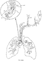
- An endoscope may be a bronchoscope and the system may further comprise a cryospray catheter as the tool to be used through the working channel of the bronchoscope.
- FIGs 19 and 20 disclose embodiments of the invention, all other embodiments of the figures are embodiments of the disclosure and not part of the invention, but useful to understand the invention.
- the systems include a lens clearing flow field adjustment mechanism that provides a flow field to purge moisture from the space adjacent to the lens of an endoscope.
- the systems incorporate a shroud and/or cap attachment for the endoscope that minimizes moist fluid entrainment and also may deflect incoming particles or bodily fluids.
- the term "lens" is to be understood as including an optical device as part of an image capture device of a distal end of an endoscope (such as one or a series of lenses that may be arranged along a common axis or a CCD) and/or a transparent protective cover or screen for the optical device.
- a purging fluid such as a gas
- a lens clearing flow field adjustment mechanism such as a nozzle
- the mechanisms may be configured in different ways to modify and direct the flow field of the purging fluid.
- a secondary nozzle is directed such that incoming particles and fluids may be deflected away from the lens assembly.
- purging fluid as a gas may be supplied through a rinse channel of the endoscope, and a cap may modify, direct, detect or cycle the flow of the gas in order to improve the lens clearing effect, drain liquids from the cap (sometimes via a phase separator mechanism), and/or deflect gases longitudinally away from the lens cover to provide a gas buffer or barrier.
- Various embodiments may also incorporate a heating element to provide purging fluid at body temperature or a slightly elevated temperature. Providing heating to the endoscope tip is needed to avoid condensation and freezing of condensates and bodily fluids in contact with the lens, a condition unique to cryotherapy procedures, particularly cryospray techniques. In addition, and not unique to cryotherapy, heating the endoscope tip may prevent condensation by keeping the lens above an ambient dew point temperature.
- Other embodiments may incorporate an electrical heating element, e.g., within a sleeve that connects the distal shroud or cap to the endoscope. In some cases, sensors and a power supply may be included to provide feedback-controlled temperature regulation of the endoscope tip.
- Exemplary embodiments of the visualization systems may be particularly well suited to applications involving endoscopic cryotherapy procedures, especially spray cryotherapy. Each of these aspects and advantages are described in more detail below.
- a visualization system includes a distal cap with a lens clearing flow field adjustment mechanism.
- the mechanism may include one or more nozzles for creating and adjusting a flow field.
- Some nozzles may be configured to deliver an angled jet of purging fluid to the lens at the distal end of an endoscope to which the cap is attached, such as a gaseous nitrogen, dry air, oxygen, or carbon dioxide jet.
- the purging fluid and nozzles may be configured within the cap in various ways to prevent condensation on the lens by purging moisture from the gas surrounding the lens cover, clearing liquids from the lens cover, and hydrodynamically deflecting incoming spatter, particulates, and fog.
- Embodiments of a distal cap attachments may take several forms.
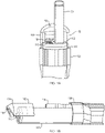
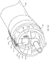
- Figures 1A and 1B depict a distal cap 102 that is asymmetric about an axis extending in a radial direction with respect to a central axis of the cap.
- the cap is connected to a heat shrink or friction sleeve 126 surrounding an endoscope 112 in which the shrouding portion 116 surrounds only a part of the distal portion of a catheter 124 and/or endoscope 112.
- Asymmetry serves among other purposes to minimize blocking of the gas egress area across the lens 110 and distal end of the endoscope 112 and reduces a profile of the cap 102 from blocking the flow of the purging fluid.
- Purging fluid as a gas may vent to a side of a patient's body around the outside of the endoscope 112.
- Figure 1A depicts a cap 102 with a lens clearing flow field adjustment mechanism that includes two nozzles: a lens clearing nozzle 104 directed towards the lens cover 110 of endoscope 112, and a spatter deflection nozzle 118 directed out and away from the lens 110 at an angle with respect to a central axis of the cap, for deflecting incoming spatter, particulates, and fog.
- a lens clearing nozzle 104 directed towards the lens cover 110 of endoscope 112
- a spatter deflection nozzle 118 directed out and away from the lens 110 at an angle with respect to a central axis of the cap, for deflecting incoming spatter, particulates, and fog.
- FIG. 1A depicts nozzle 118 oriented at an angle of approximately 135° from the central axis of the cap 102, such that spatter is barely diverted from impacting the scope.
- a visualization system may utilize zero or more lens clearing nozzles 104 and zero or more spatter deflection nozzles 118, depending on the particular application.
- Working channel 122 allows a tool, such as a cryosurgery tool, to be deployed via catheter 124 to the vicinity of the visualization system.
- Figure 1B illustrates the cap 102 in position at the distal end of the endoscope 112, but disconnected from the sleeve 126.
- Purging fluid supply mechanism 106 which is a single lumen supply tube or line along the length of the endoscope 112 in this embodiment, provides a channel to the endoscope tip via the cap 102 for purging fluid.
- the purging fluid supply mechanism 106 is in fluid communication with a fluid such as a gas, which may be room temperature or heated.
- Purging fluid supply mechanism 106 is disposed within a lumen of the sleeve 126 along the endoscope 112.
- a spatter deflection nozzle and a lens clearing nozzle are both provided with a purging fluid via a purging fluid supply mechanism (e.g., a single lumen feed tube in Figure 1B ) connected to a distal cap, e.g. cap 102, as shown in Figures 1A and 1B .
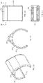
- the purging fluid supply mechanism may be secured to the endoscope at one or more points using clips.
- An exemplary clip 200 suitable for this purpose is depicted in Figures 2A-2D . As shown, clip 200 includes a first C-shaped portion 202 to accept and clip onto an endoscope 112.
- the clip 200 may include a second C-shaped portion 204 to accept and clip onto purging fluid supply mechanism 106.
- One or more clips may be used to run a purging fluid supply mechanism along the length of the endoscope.
- a cap and/or purging fluid supply mechanism may be connected to an endoscope in a number of ways.
- these elements may be connected to an endoscope via a heat shrink connection sleeve.
- a circuit and battery may be integrated into the visualization system, allowing in some embodiments a heat shrink connection sleeve to generate its own heat to in effect, self-shrink.
- the heat shrink sleeve may be externally heated with a heat gun.
- a tube and rubber roll-on cuff, sleeve, deflecting tabs, membrane for a friction fit, or the like may be employed.
- a cap and/or delivery sheath may be extruded or molded from PVC, Pebax 6333, or similar material.
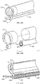
- a purging fluid supply mechanism 306 is formed by annular extrusion in a sheath covering the endoscope.
- the purging fluid supply mechanism may be formed as a multilumen extrusion in which the endoscope slides into a cylindrical sleeve that provides the purging fluid (e.g., purging fluid supply mechanism 306 and endoscope 312 in Figures. 3A-3C ), or as a single lumen extrusion in which the purging fluid supply mechanism is attached to the system using a sleeve, one or more snap-fit clips (e.g., purging fluid supply mechanism 306, sleeve 126, and clips 200 in Figures 1A-2D ), or some other means.
- any element of the visualization system may be designed as a temporary attachment means that is removed when the element or system is sterilized.
- a purging fluid supply mechanism may also be configured as an outer lumen of a multilumen sheath. The endoscope may slide into an inner lumen of the multilumen sheath, while the purging fluid is supplied to the cap via the outer lumen.
- a purging fluid for a system may be, for example, carbon dioxide (CO 2 ), nitrogen (N 2 ), dry air, or oxygen (O 2 ).
- the purging fluid may be supplied in a number of ways.
- the fluid supply mechanism is a line and may connect directly to a console, such as a cryosurgery console as described in connection with Figures 9-11B , in which nitrogen is supplied to the supply line.
- the fluid supply line may be connected to disposable canisters of purging fluid.
- the purging fluid may also be supplied via an insufflator unit, or commercial compressed gas bottles with a regulator and valve.
- a mass flow or other suitable controller may be used to regulate and/or vary a flow rate of purging fluid during operation. Pressure feedback from the supply line or taken from within a body lumen, or both, may be utilized to reduce a risk of distension or pneumothorax.
- a purging fluid may be supplied continuously to the nozzles or other lens clearing flow field adjustment mechanisms of the visualization system, or a fluid supply may be valved or metered so that the purging fluid flows on an as-needed basis.
- a button or switch may be provided that allows the flow of the purging fluid to be temporarily increased, in order to perform touch-up jobs or provide a bolus of purging fluid in the event that visualization becomes impaired despite the normal operation of the visualization system.
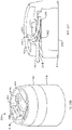
- the distal cap may be symmetrical about an axis extending in a radial direction with respect to a central axis of the cap, such that the cap has a substantially uniform profile circumference.
- a sheath or sleeve around the scope can function to both secure the cap and deliver purging fluid to the lens clearing flow field adjustment mechanism.
- an embodiment of a system includes distal cap 302 with a substantially uniform profile circumference 316 at the distal end of the cap 302.
- Purging fluid supply mechanism 306 delivers purging fluid to the lens clearing flow field adjustment mechanism, in this case nozzles 304 (and/or an additional spatter deflection nozzle(s)) on the distal end of the cap 302.
- the purging fluid supply mechanism 306 includes channels that fluidly communicate with the channels of a flow transition sheath 318 that is circumferentially mounted on the endoscope 312.
- the channels of a flow transition sheath may vary in cross-sectional width and shape along the length of the sheath. Variable cross-sections may be used to increase or decrease the mass flow rate of the fluid being supplied from the purging fluid supply mechanism, through the flow transition sheath, and to the cap.
- a cap may include one or more nozzles (e.g., a pair of nozzles 304 in Figures 3A-3C ) that are in fluid communication with the flow transition sheath and/or the purging fluid supply mechanism. Nozzles may be angled towards and across the lens and ultimately towards a drain.
- drain 314 is a gap, hole, or aperture in the cap 302 that ensures the purging fluid does not build-up at the distal end of the cap 302 within the profile circumference 316.
- the drain 314 allows for purging fluid to clear from the cap 302 and lens 310.
- Guides 308 extend from the cap 302 in proximity to the nozzles 304 in order to direct flow towards the lens 310 and drain 314 and away from catheter 324.
- the guides 308 extend only near or up to a tangential portion of the lens 310 such that they do not block the line of vision from the lens 310 to the catheter 324 extending from a working channel of the endoscope 312.
- a working channel seal e.g., seal 322 of Figure 3B , may be used to create a substantially fluid-tight seal for a catheter or other tool within the working channel such that fluids may be minimized or eliminated from entering the working channel of the endoscope.
- the lens clearing nozzle may be dimensioned, shaped, or positioned, with respect to the lens, to accomplish the desired flow field and lens clearing effect.
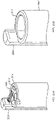
- an embodiment of a system includes cap 402 with a nozzle 404 that is directed generally across the cap 402 and towards a drain 414.
- the drain may vary in dimensions according to the particular application and desired flow, purge, or drain effects, among other effects, including, in this example, 4 mm by 1 mm.
- the nozzle 404 is supplied with purging fluid from the purging fluid supply mechanism 406 that is a channel within a wall of the cap 402.
- the nozzle 404 transitions from a wider cross-section to a narrower cross-section and is angled steeply downwards and towards the inside of the cap 402, where the lens is located once the cap 402 is mounted onto an endoscope. This allows for a narrow and aggressive flow of purging fluid across the endoscope lens cover.
- Nozzle angles for this and other embodiments may be determined depending on the application and desired flow, purge, or drain, effects, among other effects, by using, for example, computational fluid dynamics (CFD) simulation.
- a range of suitable nozzle angles may be less than 180° (180° being direct impingement on the lens with reference to a 0° angle being distal to and substantially aligned with the central axis of the cap) to about 90° (nearly parallel to the lens).
- cap 502 is shown with a nozzle 504 that is directed generally across the cap 502 and towards drain 514.
- a cross section of drain 514 is similar to drain 414.
- the nozzle 504 is supplied with purging fluid from the purging fluid supply mechanism 506 that is a channel within a wall of the cap 502.
- the nozzle 504 here transitions from a narrower cross-section to a wider cross-section and is angled less steeply downwards, compared to the nozzle of Figures 4A-4D , towards the inside of the cap 502 and the lens, once the cap 502 is mounted onto an endoscope. This allows for a wide and gentle flow of purging fluid across an endoscope.
- cross-section, transitional geometries, and angles used for this and other embodiments may be application specific and may depend on various dimensional requirements and/or desired flow, purge, drain, or deflection effects, among other effects, e.g., referring to FIGS. 5A-5D , dependent on endoscope size and the diameter of the purging fluid supply mechanism 506 in order to cover the diameter of the lens cover.
- a profile of the lens clearing flow field adjustment mechanism such as a lens clearing nozzle and/or a spatter deflection nozzle (as described in Figures 4D and 5D ) may vary depending on the application.
- the cap of Figures 4A-4D has a substantially elliptical nozzle
- the cap of Figures 5A-5D has a substantially round nozzle.
- Other nozzle profiles e.g., slot, square, triangular, a combination of shapes, etc.
- other parameters may be varied as well. Examples of parameters that may be adjusted depending on the application include the angle of the nozzles, the number of nozzles, and the flow rate of the purging fluid through the nozzles.
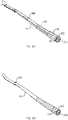
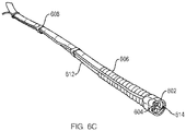
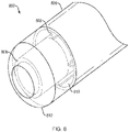
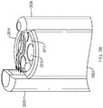
- Figures 6A-6C provide various views of an assembled visualization system with a cap 602 similar in design to the cap 502 depicted in Figures 5A-5D .
- the cap 602 includes nozzle 604 and drain 614.
- the cap 602 is connected to the endoscope 612 by a sleeve 626, and supplied with purging fluid by a purging fluid supply mechanism 606.
- the purging fluid supply mechanism 606 is disposed along the endoscope 612 and secured to the scope through the use of one or more clips 608, which may be similar in configuration to that of clip 200 in Figure 2A-2D .
- the cap may comprise materials, dimensions, and features to facilitate secure attachment to the scope.
- the base of the cap may be an elastic cuff (see, e.g., 1918, 2018, and 2118 in Figures. 19A-21C ), such as a thermoplastic elastomer (TPE) material.
- An elastic cuff may provide a friction fit component that interfaces with the endoscope outer diameter.
- Ribs may be included inside the cuff and sized and configured to meet a desired or required friction range for ease of insertion/removal onto and off of a range of endoscope outer diameters.
- Cuffs may be overmolded or made as a separate part and bonded to a transparent substrate.
- the bottom edge (proximal) of a cuff may be tapered to guide the endoscope into position during attachment at the cap.
- An outer profile of the cuff may be undersized so that when stretched over an endoscope, it expands to provide a straight/smooth outer profile.
- a cap is depicted (e.g., 1900, 2000, and 2100, respectively) with a tapered rigid plastic region (1902, 2002, and 2102) and an elastic cuff region (1918, 2018, and 2118).
- the tapered rigid plastic region has an outer diameter that is tapered, for example, at about 15 degrees.
- the cap is mounted onto an endoscope (1912, 2012, and 2112) through the frictional grip of the cuff around an end region of the endoscope. Tapering and scalloping is provided on the tapered rigid plastic region to help the user handle and fit the cap in the right position relative to the endoscope face features.
- scalloping and tapering on the distal cap may be adjusted according to preference and the circumferential distal edge of the tapered rigid plastic region (e.g., 1902, 2002, and 2102) may be fully rounded with the distal profile tapered to provide smooth, atraumatic insertion in the patient.
- the tapered rigid plastic region e.g., 1902, 2002, and 2102
- a distal cap is configured to receive purging fluid from within the endoscope, and/or the cap may include a flow deflection guide structure to direct purging fluid.
- a visualization system of the invention includes a cap 1900 with a lens clearing flow field adjustment mechanism, which is a nozzle 1904.
- the nozzle 1904 receives a purging fluid from a purging fluid supply mechanism, which is a channel in the endoscope 1912.
- the nozzle 1904 directs the purging fluid towards the lens 1910 of the endoscope 1912.
- the cap 1900 also includes a guide 1908 that directs the flow of the purging fluid after it has traveled from the nozzle 1904 and across the lens 1910.
- the guide 1908 is curved and angled toward a first drain 1914a, but may be configured differently depending on the desired flow deflection path for the purging fluid.
- the guide 1908 is curved and angled to guide the purging fluid generally in a distal direction with an angle of, for example, about 60° proximally from a radial axis of the cap.
- the guide 1908 may also deflect or recycle the fluid generally around the inside rim of the cap 1902. With gas as a purging fluid, this path can act to create a vortex in front of the cap as the gas circles distally beyond the endoscope tip 1912.
- the guide 1908 has a C-shaped notch that allows for better visibility from the lens 1910.
- the purging fluid exits from over the lens 1910 to outside of the cap 1900, clearing the area around the lens 1910 for additional purging fluid from the nozzle 1904.
- a partition 1922 prevents fluids that may accumulate beneath the guide 1908 from reaching the lens 1910.
- the partition 1922 deflects the purging gases from the nozzle 1904 to the guide 1908 while liquids are disposed of via the drain 1914b.
- the cap may be optically transparent so as not to interfere with visibility.
- portions of the cap may be made of a transparent material to improve visibility. Markings may also be included on the cap to assist in properly attaching the cap to a scope.
- the tapered rigid plastic region 1902 of the cap 1900 may be made of a transparent material, such as Lexan, so that there is a clear line of vision from the lens 1910 to the target site through the tapered rigid plastic region 1902.
- Conspicuous markings 1924 and 1926 may be printed or otherwise disposed onto the cap 1900, such as on the plastic region 1902 and the cuff region 1918.
- the marking 1924 is an alignment marking that assists the user in placing the cap 1900 onto the endoscope 1912 such that the cap 1900 and all of its features are properly aligned with the lens 1910 and working channel, and not rotationally out of position.
- the marking 1924 extends across the drain 1914a and onto the cuff 1918. A user may align the marking 1924 such that it is centered with respect to the lens 1910.
- the marking 1926 is disposed on the guide 1908. The marking 1926 is positioned perpendicular to a radius of the lens 1910 and is at a distance from the circumference of the lens 1910 such that when the cap 1900 is properly mounted onto the endoscope 1912, an image viewed through the lens 1910 does not have any portion of the marking 1926 within the field of vision.
- the cap 1900 is not properly secured to the endoscope 1912, at least a portion of the marking 1926 may be viewable through the lens 1910. This may indicate that the cap 1900 needs to be further pressed onto the distal end of the endoscope 1912 for a secure fit. Markings may be added to a cap via methods such as, e.g., pad printing, laser printing, or laser etching.
- a system within the scope of the present invention include a nozzle as a lens clearing flow field adjustment mechanism on the cap that is directed toward a lens of an endoscope, one or more guide members, and one or more drains.
- cap 2000 is shown with a lens clearing nozzle 2004.
- the nozzle 2004 delivers a purging fluid from a purging fluid supply mechanism, which is a channel in the endoscope.
- the nozzle 2004 directs the purging fluid towards the lens 2010 of endoscope 2012.
- the cap 2000 also may include a guide 2008 that directs the flow of the purging fluid after it has traveled from the nozzle 2004 and across the lens 2010.
- the guide 2008 has a wedge-shape that is both angled towards a first drain 2014a adjacent to the guide 2008 and a second drain 2014b that is below the guide 2008.
- the partition 2022 acts as a phase separator mechanism to drain liquids and/or deflect gases away from the lens cover 2010 to provide a gas buffer or barrier.
- the partition 2022 surrounding lens cover 2010 redirects the flow upward toward the guide 2008. Heavier liquids (e.g. as a liquid phase of the purging fluid) are unable to change direction quickly due to momentum, and so they exit through the second drain 2014b in a substantially radial direction away from the lens, while gases (e.g., as a gas phase of the purging fluid) are directed to guide 2008, which directs the gases in a substantially distal direction away from the lens.
- the guide 2008 may direct any gases away from the lens towards the first drain 2014a, as well as direct any gases distally away from the cap 2000. Any liquids from the purging fluid may be directed downward by the angled wedge of the guide 2008 towards the second drain 2014b, as well as directed toward the face of the endoscope 2012.
- the endoscope 2012 may have a channel that can receive the purging fluid via suction for venting and/or recycling of the purging fluid through the endoscope 2012.
- the second drain 2014b may incorporate, for example, a 90° (full quadrant) drain slot for the elimination of fluid accumulation. Purging fluid may egress from over the lens 2010 to outside of the cap 2000, clearing the area around the lens 2010 for additional flow of purging fluid from the nozzle 2004.
- the partition 2022 acts to minimize or prevent fluids that may accumulate beneath the guide 2008 from reaching the lens 2010.
- a cap of the disclosure may include a transparent lens that has a coating, and a lens clearing flow field adjustment mechanism, such as a nozzle, that may be created by a gap between the cap and the endoscope on which it is mounted.
- a lens clearing flow field adjustment mechanism such as a nozzle
- FIGs 21A-21C depict cap 2100 with lens clearing nozzle 2104.
- the nozzle 2104 delivers a purging fluid from purging fluid supply mechanism 2106, which is a channel surrounding the endoscope 2112 created by the cap 2100.
- the nozzle 2104 is created by a slant on an inner surface of the cap 2100 that narrows the gap of the purging fluid supply mechanism 2106 and directs the purging fluid towards the lens 2110 of endoscope 2112.
- a transparent lens 2122 may be inserted and installed through the drain 2114.
- a small gap may be created between the distal surface of the lens and a proximal surface of a guide 2108.
- This gap created by the guide 2108 and the transparent lens 2122 directs the flow of the purging fluid after it has traveled from the nozzle 2104 and across the lens 2110.
- the guide 2108 may direct the fluid across the distal surface of the transparent lens 2122 and towards the drain 2114.
- the purging fluid may exit from over the lens 2110, between the guide 2108 and the transparent lens 2122, across the transparent lens 2122, and outside of the cap 2100, clearing the area around the lens 2110 for additional flow of purging fluid from the nozzle 2104.
- a transparent lens may have a permanent hydrophobic and/or antireflective coating to allow universal operation with different endoscope types, brands, and sizes.
- a transparent lens may be glass, such as gorilla glass or borosilicate glass, or it may consist of highly polished polycarbonate.
- a cap may include a second transparent lens to create a double paned insulating effect.
- the system includes a catheter that is mounted to the endoscope using one or more clips.
- the cap on the endoscope includes a parallel extension through which the catheter is disposed.
- cap 2202 is mounted at the distal portion of the endoscope 2212.
- the cap may be configured as in any of the embodiments described above, or as otherwise within the scope of the present disclosure.
- a catheter 2224 may be mounted to the endoscope 2212 by using one or more clips 2204.
- the clip 2204 has a C-shape portion to accommodate and clip onto endoscope 2212.
- the clip 2204 also has a lumen to accommodate the catheter 2224.
- the lumen of the clip 2204 is offset away from the C-shape portion such that a first air gap 2206 is created between the catheter 2224 and the endoscope 2212.
- the first air gap 2206 provides thermal insulation by physically separating the endoscope 2212 from the catheter 2224.
- the lumen runs parallel with a longitudinal axis of the cap 2202 and with a longitudinal axis of the clip 2204.
- the lumen may match the outer diameter of a catheter for use with the system such as, for example, a cryospray catheter.
- the extension contains a second air gap 2208 internally that also thermally isolates the catheter from the endoscope.
- the combined width of the overall assembly at its widest point may be, for example, about 18 mm.
- the cap may have a maximum diameter of approximately 14 mm exclusive of molded transitions to the fluid supply lumen.
- the cap 2202 may overhang circumferentially around the endoscope by, for example, about 2 mm to about 4 mm, which contributes to the first gap 2206.
- the system may include an elongate multilumen sheath to accept an endoscope and a catheter with gaps to assist with thermal isolation.
- a cap may be mounted to the distal ends of the lumens of the multilumen sheath.
- An external working channel may be insulated and configured to receive a catheter with a sealed air channel or a vacuum gap that provides thermal insulation.
- Figures 23A-23C depict a system with an elongate multilumen sheath 2304, which has a larger lumen for accepting an endoscope 2312 and a smaller external working channel that is a lumen that runs parallel to the larger lumen for accepting a catheter 2324.
- the cap may be configured, as in any of the embodiments described above, or as otherwise within the scope of the present disclosure, and may be mounted at the distal portion of the larger lumen of the elongate multilumen sheath 2304.
- the elongate multilumen sheath 2304 includes a first air gap 2306 that is horse-shoe shaped and substantially surrounds the smaller lumen of the multilumen sheath 2304.
- the elongate multilumen body 2304 also includes a second air gap 2308 that is located between the first air gap 2306 and the longitudinal axis of the larger lumen.
- the catheter 2324 is outside of and away from the endoscope 2312, which keeps each thermally insulated from the other.
- any embodiment of a cap of the present disclosure may include an extension with a lumen to accommodate an end portion of the catheter.
- the cap may mount onto the distal portion of the larger lumen of the multilumen body 2304, while the extension 2314 may mount on the smaller lumen.
- the lumen of the extension 2314 may be angled towards the longitudinal axis of the larger lumen of the multilumen sheath 2304 such that the catheter 2324 bends towards the endoscope 2312 to be closer within the field of vision of the lens of the endoscope 2312.
- a system may include a seal protecting a working channel of the endoscope, as well as mounting features in the cap.
- the system includes a cap with a support rigid plastic tab 2404 with a U-shaped channel 2406 and a notch 2408.
- Tab 2404 deflects outward when mounted onto the endoscope and clamps the cap 2402 around endoscope with an amount of pressure that does not damage the endoscope.
- a bump (not shown) on the underside of tab 2404 may be included to provide an interference with the endoscope outer diameter.
- the notch 2408 may line up with a bump on the endoscope to lock the cap 2402 into place and facilitate proper alignment of the cap 2402 on the endoscope.
- the cap 2402 may have an outer diameter of, for example, about 12.5 mm Alternatively, or additionally, inner ribs may be within the cap to provide an interference fit with the endoscope.
- a working channel seal may be included with the cap to provide a substantially fluid-tight seal around a catheter or other tool within the working channel of the endoscope.
- a low durometer working channel seal 2410 is disposed around the working channel 2424 of the cap 2402 to prevent fluid ingress into the working channel 2424.
- the seal 241 may be elastic and designed for interference with the catheter shaft 2424, or may rely on a garter spring to hold the sealing material tight against the shaft 2424.
- the seal 2424 may be a radial o-ring, or other suitable configuration or material to accomplish the intended sealing and/or wiping effect.
- the seal may be made of, a soft polymer material that conforms to the outer diameter of the catheter and that is large enough to seal the entire working channel. As this feature covers the working channel and conforms to the catheter outer diameter, the amount of space for mucus or fluid ingress is drastically reduced or eliminated.
- the feature may be an o-ring that is appropriately sized (e.g., having an outer diameter larger than a working channel, and an inner diameter just undersized to a catheter outer diameter in order to provide a substantially fluid-tight fit).
- the seal may comprise a soft polymer material that can be formed to any shape so that it covers the working channel without blocking other endoscope features.
- a seal can have a self-sealing feature, e.g., a small cut or slit that allows a catheter to be pushed through it and seal around the catheter outer diameter, and then reseal itself when the catheter is removed.
- rigid or flexible wiping features may be molded or attached to a catheter's distal outer diameter that allow a catheter to pass through, pushing out fluids during insertion and blocking the majority of the working channel opening from ingress of fluids once in working position.
- a cap in various embodiments, includes an inner lip to contain an endoscope, the cap includes an egress channel to evacuate the purging fluid, and a working channel within the endoscope supplies the purging fluid.
- a cap 2502 is slidingly disposed onto endoscope 2512 and extends along the length of the endoscope 2512.
- the cap includes an inner lip 2514 at the distal end of the cap 2502 such that the endoscope 2512 may not translate distally past the lip 2514 and thus past the cap 2502.
- the cap 2502 includes an egress channel 2508 that is a lumen that runs parallel to a longitudinal axis of the cap 2502.
- the egress channel 2508 extends distally past the lip 2514 of the cap 2502 exposing a radial aperture that is oriented generally towards the center of the cap 2502.
- a channel 2506 within endoscope 2512 that is slidingly inserted into the cap 2502 supplies a lens clearing purging fluid to the distal end of the endoscope 2512.
- the cap 2502 may be rotated about the endoscope 2512 such that the egress channel 2508 is positioned on an opposing side of the lens 2510 from the channel 2506 supplying the purging fluid.
- the egress channel 2508 may be connected at a proximal end to an active suction mechanism to draw the purging fluid from the channel 2506, across the lens 2510, and into gas egress channel 2508.
- a cap in various embodiments, includes an inner lip to contain an endoscope, an egress channel to evacuate the purging fluid, and a purging fluid supply mechanism apart from a channel of an endoscope that supplies the purging fluid.
- cap 2602 is slidingly disposed onto an endoscope 2612 and extends along the length of the endoscope 2612.
- the cap includes an inner lip 2614 at the distal end of the cap 2602 such that the endoscope 2612 may not translate distally past the lip 2614 and thus past the cap 2602.
- the cap 2602 includes a purging fluid supply mechanism 2606 that is a lumen that runs parallel to a longitudinal axis of the cap 2602 to supply the purging fluid.
- the purging fluid supply mechanism 2606 extends distally past the lip 2614 of the cap 2602 exposing a radial aperture that is oriented generally towards the center of the cap 2602.
- the cap 2602 includes an egress channel 2608 that is a lumen that runs parallel to a longitudinal axis of the cap 2602 generally opposing the purging fluid supply mechanism 2606.
- the egress channel 2608 extends distally past the lip 2614 of the cap 2602 exposing a radial aperture that is oriented generally towards the center of the cap 2602.
- the egress channel 2608 extends distally past the distal end of the purging fluid supply mechanism 2606.
- the purging fluid supply mechanism 2606 and the egress channel 2608 are positioned such that the lens 2610 of the endoscope 2612 lies between the purging fluid supply mechanism 2606 and egress channel 2608.
- the egress channel 2608 is connected at a proximal end to an active suction mechanism. The suction draws the purging fluid from the working channel 2606 and across lens 2610 to clear the lens and improve visibility, and into gas egress channel 2608.
- the egress channel 2608 may also merely use passive venting rather than active suction since the purging fluid supply mechanism 2606 is supplying the purging fluid in the general direction of the egression channel 2608.
- Egress channel 2608 may extend distally beyond the purging fluid supply mechanism 2606 and include an aperture that is larger than a nozzle or aperture that receives the purging fluid from the supply mechanism in order to capture the purging fluid that may not travel directly across the endoscope 2612 towards the egress channel 2608.
- exemplary embodiments may also incorporate heating elements or other forms of temperature control, which are described in more detail in the next section.
- embodiments of the visualization system may incorporate a temperature control system, such as an active heater or a passive catheter vacuum jacket.
- the heating element may maintain safe exposure temperatures in a patient, while maintaining the lens temperature above the dew point.
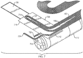
- an embodiment of a temperature control feature includes a flexible printed circuit 702 attached to an endoscope 712.
- the circuit may be attached to endoscope 712 with various means include heat shrink material or adhesive.
- a flexible printed circuit may electrically heat an endoscope and/or the purging fluid supply mechanism to avoid condensation/freezing temperatures.
- a flexible printed circuit may run along the length of the endoscope, as shown, and/or along the purging fluid supply mechanism, such that purging fluid is adequately heated when it reaches the cap.
- Embodiments of circuits may incorporate temperature sensing elements such as thermocouples, resistance temperature detectors (RTDs) or thermistors to provide control feedback to the power supply.
- the circuit may also include thermal interface materials to reduce thermal impedance between the heating element and the endoscope and/or purging fluid supply line.
- Inline heating elements may be provided with a resistive heater or a defrost heater included in the console, as described below.
- the flexible heater/sensor circuit 702 is attached to endoscope 712 by wrapping the distal "flag" 706 around the cylindrical insertion end of the endoscope 712, looping a tab 708 through a slot 710 and pulling taut to compress a gap pad 714 (underside, not shown in rendering), then securing the tab 708 back onto flag 706 using pressure sensitive adhesive pre-applied to the back of tab 708.
- circuit 702 is adhered to or printed onto the inside diameter of a heat shrinkable material (e.g., poly olefin, PET, PFA, PVC, etc.), and circuit heating element 716 is used to shrink the circuit down onto an endoscope 712 to provide a secure temporary fit.
- a heat shrink band may be perforated along the longitudinal axis for ease of removal after use, similar to a quality seal used on medicine bottles.
- Gap pad 714 is used to create a low impedance thermal connection between the heater coil 716 and the endoscope 712 to provide necessary heating to maintain a lens 718 above the dew point without reaching excessive temperature on the external (patient contacting) diameter of the assembly.
- the outside diameter of the assembly is insulated with either heat shrink sleeving, or insulated by an embodiment of a distal cap attachment as described herein, which is applied over the heater/sensor circuit 702 assembly.
- the leads to the heater/sensor circuit 702 may be constrained along the length of endoscope 712 using, for example, clips similar to the ones shown in Figures 2A-2D , or by using pressure sensitive adhesive pre-applied to a sheet of the circuit, or by using a heat shrinking sleeve as previously described.
- These and various other attachment means may be used with other configurations of circuits or with other types of temperature control features to secure the sensor/heater to the scope, catheter, or cap attachments.
- heating element 716 is powered by a DC voltage source, either within, e.g., a cryospray console or as a separate power controller.
- the heating element may be thermostatically controlled.
- the heater power may be PID loop controlled, where the process variable is the lens 718 temperature as measured by self-adhesive temperature sensor (e.g., thermocouple, RTD, or thermistor) 720 which is applied to the distal tip of the endoscope 712 by folding such that it sits adjacent to the lens 718.
- self-adhesive temperature sensor e.g., thermocouple, RTD, or thermistor
- Temperature sensors 722 are disposed circumferentially around the heating element 716 to assure that even thermal contact is made between the circuit 702 and the endoscope 712, avoiding the risk of hot spots that could exceed rated patient exposure temperatures.
- a sensor appendage 724 is similarly a safety feature containing a temperature sensor which folds back on itself over the applied heat shrink insulation to monitor the external surface temperature which is exposed to the patient.
- the sensor 712 cuts off power to the heating element 716 if an exposure temperature exceeds a preset maximum.
- the sensors 722 are compared to one another to determine a standard deviation, and similarly a warning is offered and/or power is cut off if the deviation exceeds a preset maximum.
- One or more temperature sensors are disposed longitudinally along the endoscope 712 and may be used for experimental data collection.
- the heater/sensor circuit 702 can be located along an inner layer of the assembly and a purging fluid supply mechanism may be attached/molded to the sheet of the circuit.
- the entire assembly may be pre-assembled into a tubular capped sleeve which easily slips over the length of the endoscope 712.
- the assembly may be secured through the use of heat shrinking material using heat provided by heating element 716 for ease of installation prior to a procedure.
- a system may include a vacuum jacket that thermally isolates a catheter and an atraumatic tip that maintains the vacuum in the jacket and has a generally rounded tip to avoid damaging a body lumen.
- a flexible vacuum jacket 802 is shown on a catheter and/or endoscope (not shown).
- the catheter vacuum jacket 802 reduces or eliminates convection and reduces or minimizes conduction and radiation on the external surface of the catheter.
- the jacket insulates the catheter, which may be a catheter for delivering cryospray and allows the endoscope to maintain ambient room temperature.
- the vacuum jacket 802 may be a polymer extrusion 806 having metalized inner surfaces for radiation shielding that allow for a permanent or semi-permanent vacuum to be held without outgassing of the polymer substrate.
- the extrusion 806 may include vacuum channels 810 that are evacuated lumens separated by thin ribs 808 that may be made of a material such as polyethylene terephthalate or nylon.
- An inner lumen 804 may contain a catheter and/or endoscope. The inner lumen 804 separates the catheter and/or endoscope from the vacuum created by the jacket 802.
- the inner lumen 804 may be made of a polyimide material.
- An atraumatic tip 812 may surround the inner lumen 804 to maintain the sealed vacuum and protect an end of the catheter and/or endoscope.
- the atraumatic tip 812 includes a lumen that may match with the inner lumen 804, such that medical tools, or a catheter, or an endoscope may access a target site within a patient.
- the jacket may include either additionally or alternatively, annular metal tubes separated with low conductivity spacers disposed along the length of the jacket to maintain separation between inner and outer tubes. These tubes can be welded or bonded at both ends to create an evacuated space.
- the metal tubes may be made of, for example, stainless steel or nitinol.
- the visualization systems described above may be employed in connection with any type of visualization means, such as an endoscope, and with any type of tool used with such visualization means.
- the visualization systems of the present disclosure are particularly well-suited to application in cryogenic medical systems, such as cryosurgery systems, and most particularly with cryospray catheter systems.
- cryogenic medical systems such as cryosurgery systems
- cryosurgery systems and most particularly with cryospray catheter systems.
- FIGs 9-10 a simplified perspective view of an exemplary cryosurgery system in which embodiments of the present disclosure may be implemented. It should be noted that one or more of the features described here could be applicable to other configurations of cryosurgery systems for use with any visualization system according to the present disclosure.
- a cryosurgery system 100 may comprise a pressurized cryogen storage tank 126 to store cryogen under pressure.
- the cryogen stored in tank 126 is liquid nitrogen although other cryospray may be suitable.
- the pressure for the liquefied gas in the tank 126 may range from 5 psi to 55 psi. For example, when the pressure in the tank during operation is set to 20 psi, the flow rate/cooling capacity of the nitrogen may be 25 W.
- Liquid nitrogen (LN2) resides on the bottom of the tank 126 and liquid nitrogen gas/vapor (GN2) occupies the top portion of the tank 126.
- Tank level is monitored electronically via a sensor internal to the tank 126 that changes value with the level of the liquid inside the tank 126.
- the console depicted in Figure 9 includes an emergency shut off 314, pressure sensor port 308, temperature sensor port 310 and digital input port 312.
- An interface 318 is a secure connection point for the delivery apparatus 128 to the console, such as a mating receptacle for a probe connector, such as bayonet 1202 of the probe depicted in Figures 12 and 15 .
- the console may include an RFID tag reader 306 to identify each probe as it is used and in the case of a disposable unit, ensure that each probe is only used once per procedure.
- Foot pedals may be included with system 100 to allow for convenient control of cryogen flow with pedal 110 and suction with pedal 111. However, suction does not have to be connected to the console or included as a necessary feature of the system.
- exemplary embodiments may continuously monitor and control the pressure of liquid nitrogen in the tank during use.
- the console monitors the current pressure of the tank via a pressure sensor 174.
- the software reads the current pressure from the sensor and adjusts the pressure accordingly. If pressure is too low, the software actuates the pressure build circuit valve 176 to increase the pressure to a specified threshold and then turns off. When the pressure is too high, the software turns on the vent valve 178 until the pressure reaches a specified threshold.
- a mechanical relief valve 182 on the console tank ensures that the tank pressure stays in a safe pressure range.
- a redundant burst disk 184 provides protection should the mechanical relief valve fail.
- a redundant pressure switch 180 may provide accurate tank pressure readings and is checked during the self-test.
- a cryospray system may utilize a manifold assembly, e.g., such as cryogen valve 186, manifold 196, catheter valve 188, defrost valve 190, fixed orifices 191 and 192, and catheter interface 193 of Figures 11A and 11B , to control liquid nitrogen delivered through a catheter.
- a manifold assembly e.g., such as cryogen valve 186, manifold 196, catheter valve 188, defrost valve 190, fixed orifices 191 and 192, and catheter interface 193 of Figures 11A and 11B .
- liquid nitrogen exits the tank through the lance 194 and proceeds through the cryogen valve 186 to manifold 196 where fixed orifice 192 is present to allow cold expanded gas and liquid cryogen to exit the line and cool down the internal cryogen circuit.
- the catheter valve 188 downstream of the manifold remains closed.
- a data acquisition board collects data from a thermocouple 195 located on the manifold body.
- the system software monitors data from the thermocouple 195, and opens the cryogen valve 186 to cool the manifold 196 when its temperature is above the desired set-point.
- fixed orifice 191 is provided on catheter interface 193 to allow venting of cold expanded gas to exit the line while spraying.
- each of cryogen valve 186, manifold 192, catheter valve 188 and catheter interface 193 are provided with a temperature thermocouple or sensor 195a and a heater 199 to maintain the cryogen flow path at a constant selected temperature to prevent overcooling of the system resulting from the continuous flow of cryogen through the valves and manifold assembly.
- each of the heaters may be controlled to maintain the valves, the manifold and the catheter interface at the same temperature or at different temperatures.
- a defrost function is useful for thawing a catheter after cryogen spray, before removal from the endoscope.
- a defrost circuit directs gaseous nitrogen from the top of the tank through a heater 187 and defrost valve 190 to the catheter 128.
- the defrost button on the software screen is pressed, the defrost circuit is activated for a prescribed time (e.g. 30 seconds) but can be stopped earlier at the user's discretion.
- a low voltage (24VDC) DC defrost heater delivers 6W minimum of warming/defrost performance.
- a temperature sensor may be included in a system on a catheter to provide control feedback to a console that regulates flow from a cryosource in order to maintain a certain temperature and/or cryogen dosage.
- Figure 12 depicts an exemplary catheter 1201 designed to transport liquid nitrogen (or other cryogen) from the console to the patient treatment site.
- the catheter 1201 contains a bayonet 1202 and a hub 1203 for attachment to the console at its proximal end, a laser cut hypotube 1205 to minimize kinking and breaking, which is laminated by a heat shrink wrap (or secured by other means, such as by coating with a polymer jacket applied using a dip process) to seal the fluid flow and for insulation, an insulation layer 1204 to protect the user from cold temperatures, a nozzle connection of diminishing inner diameter 1206, a second smaller ID laser cut hypotube 1207 with FEP or Pebax heatshrink wrap, a catheter/needle head 1208, marking band 1209, and a closed distal end 1210.
- Figure 15 depicts an insulator 1504 and an exemplary cross-section of a hub 1503 with a bayonet 1502 at the proximal end of a catheter assembly for attachment to a cryogen source.
- a hypotube design and construction provides additional strength and flexibility, allowing the physician to retroflex the catheter during a treatment procedure, if needed.
- a catheter package in various embodiments may contain an RFID tag that the user scans prior to use to prevent reuse and track disposable information.
- the catheter package may also contain an introducer that provides reinforcement for the catheter and helps prevent kinking during use and when placing the catheter into the endoscope.
- An alternative construction locates the RFID tag on the connector area adjacent to the bayonet.
- a bayonet connector may include a thermocouple connection that connects a thermocouple on the catheter to a console.
- a delivery catheter may be constructed out of hypotubes of different internal diameters mated to each other to make a proximal shaft and a distal shaft, with the distal shaft containing the smaller internal diameter.
- the proximal and distal shafts may be joined at a connector.
- the proximal shaft may contain a bayonet and hub for attachment to the console at its proximal end.
- the distal shaft preferably has a reduced internal diameter to be able to fit through the working channel of an endoscope, such as a bronchoscope.
- a distal tip of the catheter may contain radial spray pattern holes which make up the nozzles configured to deliver cryogen spray onto target tissue.
- the end of the catheter may be configured to have rounded tip, preferably made of a welded stainless steel sphere. This rounded tip may help reduce trauma to the tissue during catheter insertion or manipulation into the body cavities.
- a thermocouple may be included along the catheter shaft, preferably at or near the distal tip of the catheter, to provide temperature feedback to the control console, for example to better determine and control cryospray dosing and temperature at the tip of the catheter.
- the hypotubes may be all laminated with a polymeric heatshrink which seals the shaft, or seals a portion of the shaft such as a laser cut pattern, from the liquid intended to flow inside the catheter. Additionally, both hypotubes may have variable laser cut patterns to provide rigidity where needed and allow flexibility where needed. This is accomplished by varying the separation of the spiral or repeated cut pattern, as well as varying the shape of the pattern itself.
- a delivery catheter may be constructed of three layers of flexible polyimide, surrounded by a stainless steel braid, which is in turn coated with an outer layer of Pebax.
- An extrusion of Pebax over the stainless steel braid may allow the Pebax to wick through the pitch of the steel braid, helping to prevent kinking, breaking, or delamination during retroflex of the catheter.
- the Pebax also provides a desirable balance between hardness, important for smooth sliding of the catheter and general toughness, and softness, which is important for some degree of tackiness to allow the user to feel the movement of the catheter in the endoscope.
- the pitch of the stainless steel braid is configured to be fine enough to afford the required strength, but still allow the Pebax to wick through.
- the distal end of the catheter may be provided with an atraumatic tip comprised only of Pebax, in the shape of a bullnose. This construction allows for retroflex of the catheter without kinking, breaking, or delamination of the catheter.
- retroflex is used to refer to the ability of a catheter to bend or turn approximately 210° about a radius of curvature of 0.375 inch or greater.
- a catheter By adding very thin layers of metal to a catheter shaft or increasing the heat transfer coefficient in the shaft by using a hypotube or adding a braided metal for example, a catheter may be constructed to provide optimal cryo delivery to the tip of the device in a very short cycle time.
- Figure 13 depicts an exemplary catheter shaft for a cryosurgery system with a hypotube 1319 that may be used for the construction of the proximal end of the catheter shaft 1205.
- a hypotube 1319 may be used for the construction of the proximal end of the catheter shaft 1205.
- it may have a length of approximately 45 inches, but can vary from 10 inches to 100 inches in length.
- the internal diameter of the tube 1319 may be approximately 0.104 inches (3.56 mm), but can vary from 0.031 inches to 0.197 inches (0.8 mm to 5 mm), preferably from 0.039 inches to 0.157 inches (1 mm to 4 mm).
- the hypotube 1319 may be, as shown, laser cut as a spiral, but other variable cuts can be present to provide desired flexibility/rigidity along the length of the tube.
- Figure 14 depicts an exemplary catheter shaft for in a cryosurgery system with a transition 1425 of a larger diameter hypotube shaft 1419 to a smaller diameter laser cut hypotube shaft 1408.
- the transition may be configured so that a smaller diameter may be inserted for example into the working channel of an endoscope or trocar.
- the transition from large diameter to small diameter may act as a mixing point for dual phase flow gas and liquid to interact along the path of the catheter shaft and allow for the gas to once again attain the velocity of the liquid as the dual phase flow travels down the shaft. This is understood by those skilled in that art as a "nozzling" transition.
- Control of cryogen suited to desired treatment applications and parameters may be achieved in accordance with the present disclosure through a "nozzle" flow created by tailoring, for example, shafts of a certain length, diameter size and number of transitions. Transitions may occur between two hypotubes, two polymeric shafts or between a coil and hypotube or coil and polymeric shaft.
- Figure 16 depicts an exemplary catheter shaft for a cryosurgery system with an S-curve centering feature built into the distal tip.
- Figure 16 shows the bend 1602 and the alignment line 1604 that is the feature used to visually align the catheter with respect to the endoscope working channel offset.
- Figure 17 depicts an exemplary catheter shaft for a cryosurgery system with an S-curve 1702 of an alternate embodiment as seen through an endoscope visualization system.
- a method of use is to target the area to be treated by locating the catheter section 1706 between the marking bands, then rotating the catheter axially until the axial line 1704 is visible and horizontal in the line of vision. At this point the catheter tip is relatively centered with the endoscope centerline. This axial line is typically created via a pad printed or laser marking process.
- catheter shafts of the present disclosure do not need to include an S-curve feature.
- a shaft could include a radial spray head with blunt-tip geometry and one or more radial apertures arranged around a circular atraumatic tip.
- An exemplary method of using a visualization system with a cryospray catheter for vision preservation includes attaching a cap to an endoscope and inserting a catheter within the endoscope.
- the method may include supplying a purging fluid to a lens of the endoscope.
- the method may include supplying cryospray to the catheter.
- the method may include purging moisture to avoid condensation on the lens, shearing debris and bodily fluids away from the field of view, and/or deflecting spatter from the field of view.
- FIG 18A depicts an exemplary catheter shaft for a cryosurgery system with a bronchoscope 40 that may be positioned in the trachea 44, or bronchi, such as the principle bronchi 45 of a patient.
- the catheter 48 is placed in the working channel lumen 46 of the endoscope 40 and exits the working channel at the distal tip of the endoscope.
- Cryogen delivery apparatus 42 comprises a radial spray cryogen delivery catheter at distal end 42, and one or more holes 47. After insertion of the cryogen delivery apparatus into the patient, cryogen is provided to cryogen delivery catheter 48 from a cryogen source.
- a gas egress tube 43 that surrounds the endoscope may be utilized to provide additional means to evacuate cryogenic gas from the treatment area out of the patient 49. Passive lumen egress 50 is also present via management of the airway to ensure proper venting during the procedure.
- Figure 18B shows a blow-up of an alternate embodiment, in which a straight tipped catheter 42 is used without a gas
- a reference to "A and/or B,” when used in conjunction with open-ended language such as “comprising” can refer, in one embodiment, to A without B (optionally including elements other than B); in another embodiment, to B without A (optionally including elements other than A); in yet another embodiment, to both A and B (optionally including other elements); etc.
- the term “substantially” or “approximately” means plus or minus 10% (e.g., by weight or by volume), and in some embodiments, plus or minus 5%.
- Reference throughout this specification to "one example,” “an example,” “one embodiment,” or “an embodiment” means that a particular feature, structure, or characteristic described in connection with the example is included in at least one example of the present technology.
- the occurrences of the phrases “in one example,” “in an example,” “one embodiment,” or “an embodiment” in various places throughout this specification are not necessarily all referring to the same example.
- the particular features, structures, routines, steps, or characteristics may be combined in any suitable manner in one or more examples of the technology.
- the headings provided herein are for convenience only and are not intended to limit or interpret the endoscope or meaning of the claimed technology.
Landscapes
- Health & Medical Sciences (AREA)
- Life Sciences & Earth Sciences (AREA)
- Surgery (AREA)
- Animal Behavior & Ethology (AREA)
- General Health & Medical Sciences (AREA)
- Engineering & Computer Science (AREA)
- Biomedical Technology (AREA)
- Heart & Thoracic Surgery (AREA)
- Veterinary Medicine (AREA)
- Public Health (AREA)
- Nuclear Medicine, Radiotherapy & Molecular Imaging (AREA)
- Medical Informatics (AREA)
- Molecular Biology (AREA)
- Physics & Mathematics (AREA)
- Biophysics (AREA)
- Optics & Photonics (AREA)
- Pathology (AREA)
- Radiology & Medical Imaging (AREA)
- Vascular Medicine (AREA)
- Otolaryngology (AREA)
- Thermal Sciences (AREA)
- Endoscopes (AREA)
- Instruments For Viewing The Inside Of Hollow Bodies (AREA)
Description
- This application claims the benefit of priority under 35 U.S.C. § 119 to United States Provisional Patent Application Serial No.
62/328,044, filed April 27, 2006 - The present invention relates to vision preservation systems for medical devices, and particularly for endoscopes and cryospray devices.
- The primary purpose of an endoscope, video or fiber optic, is to provide visualization of anatomical lumens for either exploratory, diagnostic or interventional procedures. Visibility may be compromised when the distal tip of the scope containing the imaging device, such as charge-coupled device (CCD) capsule or fiber optic lens cover, becomes blocked. This blockage may result from any of several processes, such as: a room temperature endoscope is introduced into a warm, humid body cavity or lumen containing gas with a dew point higher than the lens cover, causing moisture to condense or "fog" on the lens (which may cause a whiteout condition in which visibility becomes severely restricted), or causing drops to impact or build-up on the lens cover (spatter); bodily fluids are put into contact with the lens cover during navigation or as a result of flow field disturbances such as those present in spray cryotherapy, ultrasonic cutting, insufflation, among others; or fog (cryo) or smoke (cutting/thermal ablation) in the target lumen impedes the visual path to the tissue.
- A number of products are currently marketed in an attempt to address the above issues. One class of products are marketed as "anti-fog" solutions, which consist of a surfactant applied to the lens cover via a cloth, sponge, or bath. The mechanism of action for surfactants is to break the surface tension of droplets which form due to condensation or spatter on the lens cover, causing the fluid to spread into a more even film which reduces visual impairment. However, such surfactants typically provide no protection against lens spatter, and furthermore must be reapplied regularly (potentially requiring that the endoscope be removed from the patient before a procedure is complete).
- Another class of marketed products preheats the endoscope prior to patient insertion to avoid condensing moisture on the lens cover. Commercial devices consist of warming packs that deliver energy through an exothermic chemical reaction, and a heated bath of surfactant to preheat and apply anti-fog solution prior to insertion. Some such products also claim that the surfactant bath is used to remove debris, while others use a warming chamber to accept an endoscope for wiping with microfiber cloths and heating, but in each case the endoscope has to be removed from the patient in order to apply heat, receive a wiping, or apply surfactant.
- Furthermore, some products provide caps to be applied to endoscopic imaging systems. Examples include various distal caps by Olympus Corporation of Tokyo, Japan, and the Halo Cap by Barrx Medical of Sunnyvale, California, now Medtronic of Fridley, Minnesota.
-
US2004/260149A1 discloses an endoscope hood.US 2012/226104 discloses an endoscope having an inclined surface which is formed around observation window at position that faces fluid jetting nozzle, but the cap of this endoscope does not comprise the features of the characterising portion of claim 1. - The invention is a visualization system as defined by claim 1.
- A cap and shroud assembly may incorporate one or more lens clearing flow field adjustment mechanisms, such as a nozzle, designed to distribute warm (e.g., room temperature or higher) purging fluid across the lens. Other flow purging mechanisms are designed to direct purging fluid or deflect spatter at an angle away from the lens. In some embodiments, features other than nozzles may create a nozzling or flow guiding effect. The lens clearing flow field adjustment mechanisms may modify or adjust the flow of the purging fluid. Fluid directed across and toward the lens purges moisture to avoid condensation on the lens and shears debris and bodily fluids away from the field of view. The heat of the purging fluid may prevent condensation by keeping the lens above the ambient dew point temperature. Fluid directed away from the lens serves the purpose of deflecting incoming particles and fluid droplets to avoid impact on the lens cover. Embodiments of the cap are designed to avoid entraining moist air from the body cavity or lumen being treated.
- The distal cap attachment serves several purposes. For example, the attachment purges the space adjacent to an endoscope lens cover of moisture to avoid condensation. Further, the cap clears debris from the endoscope lens cover, and deflects incoming matter (spatter) to avoid impact and build-up on the lens that can obscure vision. The cap can also act as a barrier to prevent tissue or mucus from blocking the lens during endoscopic insertion. In cases in which the distal attachment is provided on an endoscope employed in a cryotherapy application, the distal attachment can also serve to warm the distal tip of the endoscope.
- Embodiments of the cap may include one or more guides that extend from or around an edge of the cap in proximity to the lens clearing flow field adjustment mechanism in order to direct, deflect, or recycle flow towards the lens and/or a drain, or away from a catheter. Guides may take on many shapes to create a desired path for the purging fluid, such as curves and slants. Guides may also direct and induce turbulent flow distally to the cap and distal end of the endoscope, such as, for example, in a distal vortex to further clear or keep clear the viewing area of obstructions. Guides may include a lumen that extends proximally along the cap and actively and/or passively vents the purging fluid.
- Embodiments of the cap may include a seal disposed about a working channel of the endoscope to create a substantially fluid-tight fit for the catheter or other tool such that fluids are inhibited or prevented from entering the working channel of the endoscope, or so that the catheter does not undesirably move around within the working channel.
- Embodiments of the visualization system include a purging fluid supply mechanism that is an outer lumen of a multilumen sheath. An endoscope may slide into an inner lumen of the multilumen sheath and the purging fluid may be supplied to a lens clearing nozzle via the outer lumen. A purging fluid supply mechanism may be an independent supply line or tube attached to the outside of the endoscope.
- Embodiments of the system may include heating elements, such as one or more flexible printed circuits, that electrically heat the endoscope, lens, and/or the purging fluid supply mechanism to avoid condensation/freezing temperatures. The heating element may run along the length of the endoscope and/or the purging fluid supply mechanism such that the purging fluid is adequately heated when it reaches the cap. The devices of the system may be heat treated before, during, or in between treatments. Heating may also be performed by a heating sheath, heating wrap, or inline heater. Various types of insulation materials may be incorporated in the systems. Sensors and a power supply for the heating elements may be included for feedback control.
- Embodiments of a visualization system may include an endoscope having a lens and a working channel for a tool. A cap may be at least partially surrounding the endoscope. A system with a cap may include a lens clearing flow field adjustment mechanism for delivering purging fluid to a lens, wherein the cap is sized and configured to reduce entrainment of moisture in the vicinity of the lens. A lens clearing flow field adjustment mechanism may be configured to deliver an angled jet of purging fluid to a lens. A cap may be symmetric about an axis extending in a radial direction with respect to a central axis of the cap. A cap may be asymmetric about an axis extending in a radial direction with respect to a central axis of the cap. A cap of the invention includes an angled partition surrounding a lens that is configured to direct phase-separated purging fluid delivered to the lens, by directing a gas phase of purging fluid in a substantially distal direction away from the lens and by directing a liquid phase of the purging fluid in a substantially radial direction away from the lens. The cap further comprises a transparent lens. A cap may further comprise a second transparent lens to create a double paned insulating effect. A transparent lens may have a coating. A coating of a transparent lens may be a hydrophobic coating, an antireflective coating, or both. A cap may be coupled to an endoscope using at least one of an elastomeric sleeve providing a friction fit, a heat shrink sleeve, or one or more deflecting tabs. A purging fluid supply mechanism may be affixed to the endoscope using a heat shrink sleeve, the sleeve including circuitry disposed at least partially along the sleeve to provide a self-shrinking heat effect to the sleeve. An outer diameter of a cap may be provided with one or more scalloped features. A system may include a working channel seal for providing a substantially fluid-tight seal in an area around the working channel of the endoscope. A lens clearing flow field adjustment mechanism may be a nozzle provided in a cap. A lens clearing flow field adjustment mechanism receives a purging fluid from a purging fluid supply mechanism integrated with an endoscope, modify a flow field of the purging fluid, and direct the flow field towards a lens. A cap may partially surround a lumen in a cap in which the endoscope is provided. A cap may fully surround a lumen in the cap in which an endoscope is provided. A cap may include a spatter deflection nozzle provided in the cap for deflecting spatter away from a lens. A system includes a flow deflection guide configured to redirect a flow field of the purging fluid delivered from the lens clearing flow field adjustment mechanism. A purging fluid may be carbon dioxide, dry air, oxygen, or nitrogen. A system may include a purging fluid supply mechanism external to the endoscope for supplying a purging fluid to a cap. A purging fluid supply mechanism may be an outer lumen of a multilumen sheath, wherein an endoscope is provided in an inner lumen of the multilumen sheath and a purging fluid is supplied to a cap via the outer lumen. A purging fluid supply mechanism may be a separate lumen affixed to an endoscope. A purging fluid supply mechanism may be a lumen extending from a cap substantially parallel to a longitudinal axis of the cap. A purging fluid supply mechanism may be affixed to an endoscope using one or more of a rubber cuff providing a friction fit, a heat shrink sleeve, or one or more deflecting tabs or clips.
- Embodiments of a visualization system may include an endoscope having a lens and a working channel for a tool. A cap may surround a lens. A lens clearing nozzle may be provided in a cap for delivering purging fluid to a lens, wherein the cap is sized and configured to reduce entrainment of moisture in the vicinity of the lens. A purging fluid supply mechanism may be external to an endoscope for supplying a purging fluid to a cap. A lens clearing nozzle may be configured to deliver an angled jet of purging fluid to a lens. A purging fluid supply mechanism may be an outer lumen of a multilumen sheath, wherein an endoscope is provided in an inner lumen of the multilumen sheath and a purging fluid is supplied to a lens clearing nozzle via the outer lumen. A purging fluid supply mechanism may be a separate lumen affixed to an endoscope. A purging fluid supply mechanism may be affixed to an endoscope using one or more of a rubber cuff providing a friction fit, a heat shrink sleeve, or one or more deflecting tabs or clips. An outer lumen of a multilumen sheath may include a flow transition area for changing a flow pattern of a purging fluid in the vicinity of a cap. A system may include a working channel seal for providing a substantially fluid-tight seal in an area around a working channel of an endoscope. A system may include one or more guides for deflecting a purging fluid away from a working channel of an endoscope. A cap may include an opening in the cap opposite a lens clearing nozzle. An opening in a cap may be a lumen extending distally from the cap substantially parallel to a longitudinal axis of the cap. A guide may have a scooped shape that follows a contour around a portion of a perimeter of a cap. A guide may have an upper distal edge that is slanted at about 60 degrees proximally from a radial axis of the cap.
- Embodiments of a visualization system may include an endoscope having a lens and a working channel for a tool. A system may include a cap surrounding a lens and a lens clearing flow field adjustment mechanism provided in the cap for delivering purging fluid to the lens. A system may include a heating element for heating either or both of an endoscope and a purging fluid such that condensation on a lens is reduced as compared to supplying the purging fluid without a heating element. A lens clearing flow field adjustment mechanism may be one or more nozzles configured to deliver an angled jet of the purging fluid to a lens. A purging fluid may be supplied to a cap through a supply tube having a wall with embedded filars. A heating element may be a wound heating element around the supply tube that provides energy through the embedded filars. A heating element may be configured to heat an endoscope. One or more sensors and a power supply may be in communication with a heating element, whereby the sensors provide feedback to the power supply to control power to the heating element. One or more thermal interface materials may reduce thermal impedance between a heating element and one or both of a lens and a supply line for supplying a purging fluid to a cap. A cap may be configured to thermally insulate a heating element from a patient to maintain a safe exposure temperature on an external surface of the heating element.
- Embodiments of a visualization system may include an endoscope having a lens and an external working channel around the endoscope configured to receive a catheter. An external working channel may comprise at least one of a sealed air channel or a vacuum gap that provides thermal insulation, and a distal sealing feature configured to limit contaminant access to the external working channel. A system may include a cap surrounding a lens and a lens clearing nozzle provided in the cap for delivering an angled jet of purging fluid to the lens, wherein the cap is sized and configured to reduce entrainment of moisture in the vicinity of the lens. An external working channel may be provided in a multilumen sheath that fits over an endoscope. An external working channel may be affixed to an endoscope using at least one of a heat shrink sleeve or one or more deflecting tabs or clips. An external working channel may include evacuated lumens separated by thin ribs.
- Embodiments of a visualization system may include an endoscope having a lens, a cap at least partially covering the endoscope, and a heating sheath or wrap. A heating sheath or wrap may provide one or more of: direct heating of an outer diameter of the endoscope or a face of the endoscope, or indirect heating by integration with the cap.
- Embodiments of a visualization system may include an endoscope having a lens, a catheter, and a flexible catheter vacuum jacket for reducing one or more of convection, conduction, or radiation to an external surface of the catheter.
- Embodiments of a visualization system may include an endoscope having a lens and a heating element for heating either or both of the endoscope and a purging fluid such that condensation on the lens is reduced. A heating element may be configured to be used in conjunction with a cap or shroud providing heated or room temperature purging fluid to a lens. A cap or shroud may provide external insulation to the heating element. An endoscope may be a bronchoscope and the system may further comprise a cryospray catheter as the tool to be used through the working channel of the bronchoscope.
-
Figures 19 and20 disclose embodiments of the invention, all other embodiments of the figures are embodiments of the disclosure and not part of the invention, but useful to understand the invention. -
-
Figures 1A-1B depict a visualization system employing a cap, a sleeve, and a purging fluid supply mechanism according to an embodiment of the present disclosure. -
Figures 2A-2D depict various views of a clip according to an embodiment of the present disclosure. -
Figures 3A-3C depict various views of a visualization system including a cap, a flow transition sheath, and a purging fluid supply mechanism according to an embodiment of the present disclosure. -
Figures 4A-4D depict various views of a cap according to an embodiment of the present disclosure. -
Figures 5A-5D depict various views of a cap according to another embodiment of the present disclosure. -
Figures 6A-6C depict various views of an assembled visualization system according to embodiments of the present disclosure. -
Figure 7 depicts a heating system according to an embodiment of the present disclosure. -
Figure 8 depicts a catheter vacuum jacket according to an embodiment of the present disclosure. -
Figure 9 depicts a perspective view of an exemplary cryosurgery system that may be employed with a visualization system according to embodiments of the present disclosure. -
Figure 10 depicts a perspective view of an interior of an exemplary cryosurgery system that may be employed with a visualization system according to embodiments of the present disclosure. -
Figure 11A is a schematic showing a cryogen storage, delivery and pressure control apparatus of an exemplary cryosurgery system that may be employed with a visualization system according to embodiments of the present disclosure. -
Figure 11B is a schematic showing a cryogen storage, delivery and pressure control apparatus of an exemplary cryosurgery system that may be employed with a visualization system according to embodiments of the present disclosure. -
Figure 12 depicts an isometric view of an exemplary radial spray catheter for a cryosurgery system that may be employed with a visualization system according to embodiments of the present disclosure. -
Figure 13 depicts a side view of an exemplary cryospray catheter for a cryosurgery system that may be employed with a visualization system according to embodiments of the present disclosure. -
Figure 14 depicts a side view of an exemplary cryospray catheter construction for a cryosurgery system that may be employed with a visualization system according to embodiments of the present disclosure. -
Figure 15 depicts an insulator and connector housing area with a bayonet connector for an exemplary cryospray catheter for a cryosurgery system that may be employed with a visualization system according to embodiments of the present disclosure. -
Figure 16 depicts an S-curve centering feature of an exemplary cryospray catheter for a cryosurgery system that may be employed with a visualization system according to embodiments of the present disclosure. -
Figure 17 depicts an S-curve centering feature and axial line as viewed through an endoscope with an exemplary cryospray catheter for a cryosurgery system that may be employed with a visualization system according to embodiments of the present disclosure. -
Figure 18A depicts a perspective view, including a blow-up view, of a portion of a cryosurgery system of an exemplary cryosurgery system that may be employed with a visualization system according to embodiments of the present disclosure. -
Figure 18B depicts an exemplary cryosurgery system with a visualization system that may be employed according to an embodiment of the present disclosure. -
Figures 19A-19E depict a cap according to an embodiment of the present invention. -
Figures 20A-20C depict a cap according to another embodiment of the present invention. -
Figures 21A-21C depicts a cap according to a further embodiment of the present disclosure. -
Figures 22A-22B depict a cap and clip according to an embodiment of the present disclosure. -
Figures 23A-23C depict a multilumen sheath and a cap according to an embodiment of the present disclosure. -
Figure 24 depicts a cap according to an embodiment of the present disclosure. -
Figures 25A and 25B depict a cap according to another embodiment of the present disclosure. -
Figure 26 depicts a cap according to yet another embodiment of the present disclosure. - The systems include a lens clearing flow field adjustment mechanism that provides a flow field to purge moisture from the space adjacent to the lens of an endoscope. The systems incorporate a shroud and/or cap attachment for the endoscope that minimizes moist fluid entrainment and also may deflect incoming particles or bodily fluids. The term "lens" is to be understood as including an optical device as part of an image capture device of a distal end of an endoscope (such as one or a series of lenses that may be arranged along a common axis or a CCD) and/or a transparent protective cover or screen for the optical device.
- In some embodiments, a purging fluid, such as a gas, is introduced to a lens from a lens clearing flow field adjustment mechanism, such as a nozzle, to clear particles or fluids from the lens cover. The mechanisms, such as nozzles, may be configured in different ways to modify and direct the flow field of the purging fluid. In some embodiments, a secondary nozzle is directed such that incoming particles and fluids may be deflected away from the lens assembly. In further embodiments, purging fluid as a gas may be supplied through a rinse channel of the endoscope, and a cap may modify, direct, detect or cycle the flow of the gas in order to improve the lens clearing effect, drain liquids from the cap (sometimes via a phase separator mechanism), and/or deflect gases longitudinally away from the lens cover to provide a gas buffer or barrier.
- Various embodiments may also incorporate a heating element to provide purging fluid at body temperature or a slightly elevated temperature. Providing heating to the endoscope tip is needed to avoid condensation and freezing of condensates and bodily fluids in contact with the lens, a condition unique to cryotherapy procedures, particularly cryospray techniques. In addition, and not unique to cryotherapy, heating the endoscope tip may prevent condensation by keeping the lens above an ambient dew point temperature. Other embodiments may incorporate an electrical heating element, e.g., within a sleeve that connects the distal shroud or cap to the endoscope. In some cases, sensors and a power supply may be included to provide feedback-controlled temperature regulation of the endoscope tip.
- Exemplary embodiments of the visualization systems may be particularly well suited to applications involving endoscopic cryotherapy procedures, especially spray cryotherapy. Each of these aspects and advantages are described in more detail below.
- In various embodiments, a visualization system includes a distal cap with a lens clearing flow field adjustment mechanism. The mechanism may include one or more nozzles for creating and adjusting a flow field. Some nozzles may be configured to deliver an angled jet of purging fluid to the lens at the distal end of an endoscope to which the cap is attached, such as a gaseous nitrogen, dry air, oxygen, or carbon dioxide jet. The purging fluid and nozzles may be configured within the cap in various ways to prevent condensation on the lens by purging moisture from the gas surrounding the lens cover, clearing liquids from the lens cover, and hydrodynamically deflecting incoming spatter, particulates, and fog.
- Embodiments of a distal cap attachments may take several forms. For example,
Figures 1A and 1B depict adistal cap 102 that is asymmetric about an axis extending in a radial direction with respect to a central axis of the cap. The cap is connected to a heat shrink orfriction sleeve 126 surrounding anendoscope 112 in which theshrouding portion 116 surrounds only a part of the distal portion of acatheter 124 and/orendoscope 112. Asymmetry serves among other purposes to minimize blocking of the gas egress area across thelens 110 and distal end of theendoscope 112 and reduces a profile of thecap 102 from blocking the flow of the purging fluid. Purging fluid as a gas may vent to a side of a patient's body around the outside of theendoscope 112. -
Figure 1A depicts acap 102 with a lens clearing flow field adjustment mechanism that includes two nozzles: alens clearing nozzle 104 directed towards thelens cover 110 ofendoscope 112, and aspatter deflection nozzle 118 directed out and away from thelens 110 at an angle with respect to a central axis of the cap, for deflecting incoming spatter, particulates, and fog. There may be benefits for any range of angles from a 0° angle (pointing distally and substantially aligned with the central axis of the cap) to an angle capturing the line of sight betweennozzle 118 and the edge ofscope 112.FIG. 1A depictsnozzle 118 oriented at an angle of approximately 135° from the central axis of thecap 102, such that spatter is barely diverted from impacting the scope. A visualization system may utilize zero or morelens clearing nozzles 104 and zero or morespatter deflection nozzles 118, depending on the particular application. Workingchannel 122 allows a tool, such as a cryosurgery tool, to be deployed viacatheter 124 to the vicinity of the visualization system. -
Figure 1B illustrates thecap 102 in position at the distal end of theendoscope 112, but disconnected from thesleeve 126. Purgingfluid supply mechanism 106, which is a single lumen supply tube or line along the length of theendoscope 112 in this embodiment, provides a channel to the endoscope tip via thecap 102 for purging fluid. The purgingfluid supply mechanism 106 is in fluid communication with a fluid such as a gas, which may be room temperature or heated. Purgingfluid supply mechanism 106 is disposed within a lumen of thesleeve 126 along theendoscope 112. - In some embodiments, a spatter deflection nozzle and a lens clearing nozzle are both provided with a purging fluid via a purging fluid supply mechanism (e.g., a single lumen feed tube in
Figure 1B ) connected to a distal cap,e.g. cap 102, as shown inFigures 1A and 1B . The purging fluid supply mechanism may be secured to the endoscope at one or more points using clips. Anexemplary clip 200 suitable for this purpose is depicted inFigures 2A-2D . As shown,clip 200 includes a first C-shapedportion 202 to accept and clip onto anendoscope 112. Theclip 200 may include a second C-shapedportion 204 to accept and clip onto purgingfluid supply mechanism 106. One or more clips may be used to run a purging fluid supply mechanism along the length of the endoscope. - A cap and/or purging fluid supply mechanism may be connected to an endoscope in a number of ways. For example, these elements may be connected to an endoscope via a heat shrink connection sleeve. In some embodiments, a circuit and battery may be integrated into the visualization system, allowing in some embodiments a heat shrink connection sleeve to generate its own heat to in effect, self-shrink. Alternatively, or in addition, the heat shrink sleeve may be externally heated with a heat gun. In other embodiments for connecting a cap and/or a purging fluid supply mechanism to the endoscope, a tube and rubber roll-on cuff, sleeve, deflecting tabs, membrane for a friction fit, or the like, may be employed. A cap and/or delivery sheath may be extruded or molded from PVC, Pebax 6333, or similar material.
- In the example of
Figures 3A-3C , a purgingfluid supply mechanism 306 is formed by annular extrusion in a sheath covering the endoscope. The purging fluid supply mechanism may be formed as a multilumen extrusion in which the endoscope slides into a cylindrical sleeve that provides the purging fluid (e.g., purgingfluid supply mechanism 306 andendoscope 312 inFigures. 3A-3C ), or as a single lumen extrusion in which the purging fluid supply mechanism is attached to the system using a sleeve, one or more snap-fit clips (e.g., purgingfluid supply mechanism 306,sleeve 126, and clips 200 inFigures 1A-2D ), or some other means. Still further, any element of the visualization system may be designed as a temporary attachment means that is removed when the element or system is sterilized. A purging fluid supply mechanism may also be configured as an outer lumen of a multilumen sheath. The endoscope may slide into an inner lumen of the multilumen sheath, while the purging fluid is supplied to the cap via the outer lumen. - In various embodiments, a purging fluid for a system may be, for example, carbon dioxide (CO2), nitrogen (N2), dry air, or oxygen (O2). The purging fluid may be supplied in a number of ways. In one embodiment, the fluid supply mechanism is a line and may connect directly to a console, such as a cryosurgery console as described in connection with
Figures 9-11B , in which nitrogen is supplied to the supply line. In other embodiments, the fluid supply line may be connected to disposable canisters of purging fluid. The purging fluid may also be supplied via an insufflator unit, or commercial compressed gas bottles with a regulator and valve. A mass flow or other suitable controller may be used to regulate and/or vary a flow rate of purging fluid during operation. Pressure feedback from the supply line or taken from within a body lumen, or both, may be utilized to reduce a risk of distension or pneumothorax. - A purging fluid may be supplied continuously to the nozzles or other lens clearing flow field adjustment mechanisms of the visualization system, or a fluid supply may be valved or metered so that the purging fluid flows on an as-needed basis. In some embodiments, a button or switch may be provided that allows the flow of the purging fluid to be temporarily increased, in order to perform touch-up jobs or provide a bolus of purging fluid in the event that visualization becomes impaired despite the normal operation of the visualization system.
- In some embodiments, the distal cap may be symmetrical about an axis extending in a radial direction with respect to a central axis of the cap, such that the cap has a substantially uniform profile circumference. By making the cap symmetrical, for example, a sheath or sleeve around the scope can function to both secure the cap and deliver purging fluid to the lens clearing flow field adjustment mechanism. For example, referring to
Figures 3A-3C , an embodiment of a system includesdistal cap 302 with a substantiallyuniform profile circumference 316 at the distal end of thecap 302. Purgingfluid supply mechanism 306 delivers purging fluid to the lens clearing flow field adjustment mechanism, in this case nozzles 304 (and/or an additional spatter deflection nozzle(s)) on the distal end of thecap 302. The purgingfluid supply mechanism 306 includes channels that fluidly communicate with the channels of aflow transition sheath 318 that is circumferentially mounted on theendoscope 312. - The channels of a flow transition sheath may vary in cross-sectional width and shape along the length of the sheath. Variable cross-sections may be used to increase or decrease the mass flow rate of the fluid being supplied from the purging fluid supply mechanism, through the flow transition sheath, and to the cap. A cap may include one or more nozzles (e.g., a pair of
nozzles 304 inFigures 3A-3C ) that are in fluid communication with the flow transition sheath and/or the purging fluid supply mechanism. Nozzles may be angled towards and across the lens and ultimately towards a drain. For example, inFigures 3A-3C , drain 314 is a gap, hole, or aperture in thecap 302 that ensures the purging fluid does not build-up at the distal end of thecap 302 within theprofile circumference 316. Thedrain 314 allows for purging fluid to clear from thecap 302 andlens 310.Guides 308 extend from thecap 302 in proximity to thenozzles 304 in order to direct flow towards thelens 310 and drain 314 and away fromcatheter 324. Theguides 308 extend only near or up to a tangential portion of thelens 310 such that they do not block the line of vision from thelens 310 to thecatheter 324 extending from a working channel of theendoscope 312. - A working channel seal, e.g., seal 322 of
Figure 3B , may be used to create a substantially fluid-tight seal for a catheter or other tool within the working channel such that fluids may be minimized or eliminated from entering the working channel of the endoscope. - In various embodiments, the lens clearing nozzle, as an example of the flow field adjustment mechanism for the purging fluid, may be dimensioned, shaped, or positioned, with respect to the lens, to accomplish the desired flow field and lens clearing effect. For example, referring to
Figures 4A-4D , an embodiment of a system includescap 402 with anozzle 404 that is directed generally across thecap 402 and towards adrain 414. The drain may vary in dimensions according to the particular application and desired flow, purge, or drain effects, among other effects, including, in this example, 4 mm by 1 mm. Thenozzle 404 is supplied with purging fluid from the purgingfluid supply mechanism 406 that is a channel within a wall of thecap 402. Thenozzle 404 transitions from a wider cross-section to a narrower cross-section and is angled steeply downwards and towards the inside of thecap 402, where the lens is located once thecap 402 is mounted onto an endoscope. This allows for a narrow and aggressive flow of purging fluid across the endoscope lens cover. - Nozzle angles for this and other embodiments may be determined depending on the application and desired flow, purge, or drain, effects, among other effects, by using, for example, computational fluid dynamics (CFD) simulation. A range of suitable nozzle angles may be less than 180° (180° being direct impingement on the lens with reference to a 0° angle being distal to and substantially aligned with the central axis of the cap) to about 90° (nearly parallel to the lens).
- As another example, referring to
Figures 5A-5D ,cap 502 is shown with anozzle 504 that is directed generally across thecap 502 and towardsdrain 514. A cross section ofdrain 514 is similar to drain 414. Thenozzle 504 is supplied with purging fluid from the purgingfluid supply mechanism 506 that is a channel within a wall of thecap 502. Thenozzle 504 here transitions from a narrower cross-section to a wider cross-section and is angled less steeply downwards, compared to the nozzle ofFigures 4A-4D , towards the inside of thecap 502 and the lens, once thecap 502 is mounted onto an endoscope. This allows for a wide and gentle flow of purging fluid across an endoscope. - The cross-section, transitional geometries, and angles used for this and other embodiments may be application specific and may depend on various dimensional requirements and/or desired flow, purge, drain, or deflection effects, among other effects, e.g., referring to
FIGS. 5A-5D , dependent on endoscope size and the diameter of the purgingfluid supply mechanism 506 in order to cover the diameter of the lens cover. - A profile of the lens clearing flow field adjustment mechanism, such as a lens clearing nozzle and/or a spatter deflection nozzle (as described in
Figures 4D and5D ) may vary depending on the application. For example, the cap ofFigures 4A-4D has a substantially elliptical nozzle, whereas the cap ofFigures 5A-5D has a substantially round nozzle. Other nozzle profiles (e.g., slot, square, triangular, a combination of shapes, etc.) may be employed. In addition to varying the profile of the nozzles, other parameters may be varied as well. Examples of parameters that may be adjusted depending on the application include the angle of the nozzles, the number of nozzles, and the flow rate of the purging fluid through the nozzles. - As a further example,
Figures 6A-6C provide various views of an assembled visualization system with acap 602 similar in design to thecap 502 depicted inFigures 5A-5D . Thecap 602 includesnozzle 604 and drain 614. Thecap 602 is connected to theendoscope 612 by asleeve 626, and supplied with purging fluid by a purgingfluid supply mechanism 606. The purgingfluid supply mechanism 606 is disposed along theendoscope 612 and secured to the scope through the use of one ormore clips 608, which may be similar in configuration to that ofclip 200 inFigure 2A-2D . - In various embodiments, the cap may comprise materials, dimensions, and features to facilitate secure attachment to the scope. For example, referring to
Figures. 19A-21C , the base of the cap may be an elastic cuff (see, e.g., 1918, 2018, and 2118 inFigures. 19A-21C ), such as a thermoplastic elastomer (TPE) material. An elastic cuff may provide a friction fit component that interfaces with the endoscope outer diameter. Ribs may be included inside the cuff and sized and configured to meet a desired or required friction range for ease of insertion/removal onto and off of a range of endoscope outer diameters. Cuffs may be overmolded or made as a separate part and bonded to a transparent substrate. The bottom edge (proximal) of a cuff may be tapered to guide the endoscope into position during attachment at the cap. An outer profile of the cuff may be undersized so that when stretched over an endoscope, it expands to provide a straight/smooth outer profile. - In each of
Figures 19A ,20A , and21A , a cap is depicted (e.g., 1900, 2000, and 2100, respectively) with a tapered rigid plastic region (1902, 2002, and 2102) and an elastic cuff region (1918, 2018, and 2118). The tapered rigid plastic region has an outer diameter that is tapered, for example, at about 15 degrees. The cap is mounted onto an endoscope (1912, 2012, and 2112) through the frictional grip of the cuff around an end region of the endoscope. Tapering and scalloping is provided on the tapered rigid plastic region to help the user handle and fit the cap in the right position relative to the endoscope face features. - In this and other embodiments, scalloping and tapering on the distal cap may be adjusted according to preference and the circumferential distal edge of the tapered rigid plastic region (e.g., 1902, 2002, and 2102) may be fully rounded with the distal profile tapered to provide smooth, atraumatic insertion in the patient.
- A distal cap is configured to receive purging fluid from within the endoscope, and/or the cap may include a flow deflection guide structure to direct purging fluid. For example, referring to
Figures 19A-19E , an embodiment of a visualization system of the invention includes acap 1900 with a lens clearing flow field adjustment mechanism, which is anozzle 1904. Thenozzle 1904 receives a purging fluid from a purging fluid supply mechanism, which is a channel in theendoscope 1912. Thenozzle 1904 directs the purging fluid towards thelens 1910 of theendoscope 1912. Thecap 1900 also includes aguide 1908 that directs the flow of the purging fluid after it has traveled from thenozzle 1904 and across thelens 1910. - The
guide 1908 is curved and angled toward afirst drain 1914a, but may be configured differently depending on the desired flow deflection path for the purging fluid. Theguide 1908 is curved and angled to guide the purging fluid generally in a distal direction with an angle of, for example, about 60° proximally from a radial axis of the cap. Theguide 1908 may also deflect or recycle the fluid generally around the inside rim of thecap 1902. With gas as a purging fluid, this path can act to create a vortex in front of the cap as the gas circles distally beyond theendoscope tip 1912. Theguide 1908 has a C-shaped notch that allows for better visibility from thelens 1910. The purging fluid exits from over thelens 1910 to outside of thecap 1900, clearing the area around thelens 1910 for additional purging fluid from thenozzle 1904. Apartition 1922 prevents fluids that may accumulate beneath theguide 1908 from reaching thelens 1910. Thepartition 1922 deflects the purging gases from thenozzle 1904 to theguide 1908 while liquids are disposed of via thedrain 1914b. This includespartition 1922 acting as a "phase separator", e.g., by directing phase-separated purging fluid delivered to the lens, by directing a gas phase of purging fluid in a substantially distal direction away from the lens and by directing a liquid phase of the purging fluid in a substantially radial direction away from the lens. Referring toFigures 19B and19D , the cap may be optically transparent so as not to interfere with visibility. - In these and other embodiments, portions of the cap may be made of a transparent material to improve visibility. Markings may also be included on the cap to assist in properly attaching the cap to a scope. For example, in
Figure 19B , the tapered rigidplastic region 1902 of thecap 1900 may be made of a transparent material, such as Lexan, so that there is a clear line of vision from thelens 1910 to the target site through the tapered rigidplastic region 1902.Conspicuous markings cap 1900, such as on theplastic region 1902 and thecuff region 1918. The marking 1924 is an alignment marking that assists the user in placing thecap 1900 onto theendoscope 1912 such that thecap 1900 and all of its features are properly aligned with thelens 1910 and working channel, and not rotationally out of position. The marking 1924 extends across thedrain 1914a and onto thecuff 1918. A user may align the marking 1924 such that it is centered with respect to thelens 1910. Additionally, the marking 1926 is disposed on theguide 1908. The marking 1926 is positioned perpendicular to a radius of thelens 1910 and is at a distance from the circumference of thelens 1910 such that when thecap 1900 is properly mounted onto theendoscope 1912, an image viewed through thelens 1910 does not have any portion of the marking 1926 within the field of vision. If thecap 1900 is not properly secured to theendoscope 1912, at least a portion of the marking 1926 may be viewable through thelens 1910. This may indicate that thecap 1900 needs to be further pressed onto the distal end of theendoscope 1912 for a secure fit. Markings may be added to a cap via methods such as, e.g., pad printing, laser printing, or laser etching. - A system within the scope of the present invention include a nozzle as a lens clearing flow field adjustment mechanism on the cap that is directed toward a lens of an endoscope, one or more guide members, and one or more drains. For example, referring to
Figures 20A-20C ,cap 2000 is shown with alens clearing nozzle 2004. Thenozzle 2004 delivers a purging fluid from a purging fluid supply mechanism, which is a channel in the endoscope. Thenozzle 2004 directs the purging fluid towards thelens 2010 ofendoscope 2012. Thecap 2000 also may include aguide 2008 that directs the flow of the purging fluid after it has traveled from thenozzle 2004 and across thelens 2010. Theguide 2008 has a wedge-shape that is both angled towards afirst drain 2014a adjacent to theguide 2008 and asecond drain 2014b that is below theguide 2008. Thepartition 2022 acts as a phase separator mechanism to drain liquids and/or deflect gases away from thelens cover 2010 to provide a gas buffer or barrier. Thepartition 2022 surrounding lens cover 2010 redirects the flow upward toward theguide 2008. Heavier liquids (e.g. as a liquid phase of the purging fluid) are unable to change direction quickly due to momentum, and so they exit through thesecond drain 2014b in a substantially radial direction away from the lens, while gases (e.g., as a gas phase of the purging fluid) are directed to guide 2008, which directs the gases in a substantially distal direction away from the lens. Theguide 2008 may direct any gases away from the lens towards thefirst drain 2014a, as well as direct any gases distally away from thecap 2000. Any liquids from the purging fluid may be directed downward by the angled wedge of theguide 2008 towards thesecond drain 2014b, as well as directed toward the face of theendoscope 2012. Theendoscope 2012 may have a channel that can receive the purging fluid via suction for venting and/or recycling of the purging fluid through theendoscope 2012. Thesecond drain 2014b may incorporate, for example, a 90° (full quadrant) drain slot for the elimination of fluid accumulation. Purging fluid may egress from over thelens 2010 to outside of thecap 2000, clearing the area around thelens 2010 for additional flow of purging fluid from thenozzle 2004. Thepartition 2022 acts to minimize or prevent fluids that may accumulate beneath theguide 2008 from reaching thelens 2010. - In various embodiments, a cap of the disclosure may include a transparent lens that has a coating, and a lens clearing flow field adjustment mechanism, such as a nozzle, that may be created by a gap between the cap and the endoscope on which it is mounted. For example,
Figures 21A-21C depictcap 2100 withlens clearing nozzle 2104. Thenozzle 2104 delivers a purging fluid from purgingfluid supply mechanism 2106, which is a channel surrounding theendoscope 2112 created by thecap 2100. Thenozzle 2104 is created by a slant on an inner surface of thecap 2100 that narrows the gap of the purgingfluid supply mechanism 2106 and directs the purging fluid towards thelens 2110 ofendoscope 2112. Atransparent lens 2122 may be inserted and installed through thedrain 2114. With thetransparent lens 2122 in position over thelens 2110, a small gap may be created between the distal surface of the lens and a proximal surface of aguide 2108. This gap created by theguide 2108 and thetransparent lens 2122 directs the flow of the purging fluid after it has traveled from thenozzle 2104 and across thelens 2110. Theguide 2108 may direct the fluid across the distal surface of thetransparent lens 2122 and towards thedrain 2114. The purging fluid may exit from over thelens 2110, between theguide 2108 and thetransparent lens 2122, across thetransparent lens 2122, and outside of thecap 2100, clearing the area around thelens 2110 for additional flow of purging fluid from thenozzle 2104. This configuration of the transparent lens may create a double paned insulating effect that further protects the lens, and may be incorporated in other embodiments. In various embodiments, a transparent lens may have a permanent hydrophobic and/or antireflective coating to allow universal operation with different endoscope types, brands, and sizes. A transparent lens may be glass, such as gorilla glass or borosilicate glass, or it may consist of highly polished polycarbonate. A cap may include a second transparent lens to create a double paned insulating effect. - In various embodiments, the system includes a catheter that is mounted to the endoscope using one or more clips. The cap on the endoscope includes a parallel extension through which the catheter is disposed. For example, referring to
Figures 22A and 22B ,cap 2202 is mounted at the distal portion of theendoscope 2212. The cap may be configured as in any of the embodiments described above, or as otherwise within the scope of the present disclosure. Acatheter 2224 may be mounted to theendoscope 2212 by using one ormore clips 2204. Theclip 2204 has a C-shape portion to accommodate and clip ontoendoscope 2212. Theclip 2204 also has a lumen to accommodate thecatheter 2224. The lumen of theclip 2204 is offset away from the C-shape portion such that afirst air gap 2206 is created between thecatheter 2224 and theendoscope 2212. Thefirst air gap 2206 provides thermal insulation by physically separating theendoscope 2212 from thecatheter 2224. The lumen runs parallel with a longitudinal axis of thecap 2202 and with a longitudinal axis of theclip 2204. The lumen may match the outer diameter of a catheter for use with the system such as, for example, a cryospray catheter. The extension contains asecond air gap 2208 internally that also thermally isolates the catheter from the endoscope. The combined width of the overall assembly at its widest point may be, for example, about 18 mm. The cap may have a maximum diameter of approximately 14 mm exclusive of molded transitions to the fluid supply lumen. Thecap 2202 may overhang circumferentially around the endoscope by, for example, about 2 mm to about 4 mm, which contributes to thefirst gap 2206. - In various embodiments, the system may include an elongate multilumen sheath to accept an endoscope and a catheter with gaps to assist with thermal isolation. A cap may be mounted to the distal ends of the lumens of the multilumen sheath. An external working channel may be insulated and configured to receive a catheter with a sealed air channel or a vacuum gap that provides thermal insulation. For example,
Figures 23A-23C depict a system with anelongate multilumen sheath 2304, which has a larger lumen for accepting anendoscope 2312 and a smaller external working channel that is a lumen that runs parallel to the larger lumen for accepting acatheter 2324. The cap may be configured, as in any of the embodiments described above, or as otherwise within the scope of the present disclosure, and may be mounted at the distal portion of the larger lumen of theelongate multilumen sheath 2304. Theelongate multilumen sheath 2304 includes afirst air gap 2306 that is horse-shoe shaped and substantially surrounds the smaller lumen of themultilumen sheath 2304. Theelongate multilumen body 2304 also includes asecond air gap 2308 that is located between thefirst air gap 2306 and the longitudinal axis of the larger lumen. Thecatheter 2324 is outside of and away from theendoscope 2312, which keeps each thermally insulated from the other. Additionally, thefirst air gap 2306 andsecond air gap 2308 assist in thermally insulating thecatheter 2324 from theendoscope 2312. Any embodiment of a cap of the present disclosure may include an extension with a lumen to accommodate an end portion of the catheter. The cap may mount onto the distal portion of the larger lumen of themultilumen body 2304, while theextension 2314 may mount on the smaller lumen. The lumen of theextension 2314 may be angled towards the longitudinal axis of the larger lumen of themultilumen sheath 2304 such that thecatheter 2324 bends towards theendoscope 2312 to be closer within the field of vision of the lens of theendoscope 2312. - In various embodiments, a system may include a seal protecting a working channel of the endoscope, as well as mounting features in the cap. For example, referring to
Figure 24 , the system includes a cap with a supportrigid plastic tab 2404 with aU-shaped channel 2406 and anotch 2408.Tab 2404 deflects outward when mounted onto the endoscope and clamps thecap 2402 around endoscope with an amount of pressure that does not damage the endoscope. A bump (not shown) on the underside oftab 2404 may be included to provide an interference with the endoscope outer diameter. Thenotch 2408 may line up with a bump on the endoscope to lock thecap 2402 into place and facilitate proper alignment of thecap 2402 on the endoscope. Thecap 2402 may have an outer diameter of, for example, about 12.5 mm Alternatively, or additionally, inner ribs may be within the cap to provide an interference fit with the endoscope. - During endoscopic and bronchoscopy procedures with spray cryotherapy, the working channel of the endoscope is often subjected to mucus, soft tissue spatter and other liquids that may enter the length of the working channel. This is particularly problematic for cryotherapy procedures as these materials have direct contact with the catheter delivering the cryogen. The direct contact with the additional thermal mass causes a decrease in cryotherapy performance as the output of the catheter is significantly reduced. In some embodiments, a working channel seal may be included with the cap to provide a substantially fluid-tight seal around a catheter or other tool within the working channel of the endoscope. For example, in
Figure 24 , a low durometer workingchannel seal 2410 is disposed around the workingchannel 2424 of thecap 2402 to prevent fluid ingress into the working channel 2424.The seal 241 may be elastic and designed for interference with thecatheter shaft 2424, or may rely on a garter spring to hold the sealing material tight against theshaft 2424. Theseal 2424 may be a radial o-ring, or other suitable configuration or material to accomplish the intended sealing and/or wiping effect. - The seal may be made of, a soft polymer material that conforms to the outer diameter of the catheter and that is large enough to seal the entire working channel. As this feature covers the working channel and conforms to the catheter outer diameter, the amount of space for mucus or fluid ingress is drastically reduced or eliminated. The feature may be an o-ring that is appropriately sized (e.g., having an outer diameter larger than a working channel, and an inner diameter just undersized to a catheter outer diameter in order to provide a substantially fluid-tight fit). In addition, the seal may comprise a soft polymer material that can be formed to any shape so that it covers the working channel without blocking other endoscope features. A seal can have a self-sealing feature, e.g., a small cut or slit that allows a catheter to be pushed through it and seal around the catheter outer diameter, and then reseal itself when the catheter is removed.
- Alternatively, or in addition, rigid or flexible wiping features may be molded or attached to a catheter's distal outer diameter that allow a catheter to pass through, pushing out fluids during insertion and blocking the majority of the working channel opening from ingress of fluids once in working position.
- In various embodiments, a cap includes an inner lip to contain an endoscope, the cap includes an egress channel to evacuate the purging fluid, and a working channel within the endoscope supplies the purging fluid. For example, referring to
Figures 25A and 25B , acap 2502 is slidingly disposed ontoendoscope 2512 and extends along the length of theendoscope 2512. The cap includes aninner lip 2514 at the distal end of thecap 2502 such that theendoscope 2512 may not translate distally past thelip 2514 and thus past thecap 2502. Thecap 2502 includes anegress channel 2508 that is a lumen that runs parallel to a longitudinal axis of thecap 2502. Theegress channel 2508 extends distally past thelip 2514 of thecap 2502 exposing a radial aperture that is oriented generally towards the center of thecap 2502. Achannel 2506 withinendoscope 2512 that is slidingly inserted into thecap 2502 supplies a lens clearing purging fluid to the distal end of theendoscope 2512. Thecap 2502 may be rotated about theendoscope 2512 such that theegress channel 2508 is positioned on an opposing side of thelens 2510 from thechannel 2506 supplying the purging fluid. Theegress channel 2508 may be connected at a proximal end to an active suction mechanism to draw the purging fluid from thechannel 2506, across thelens 2510, and intogas egress channel 2508. - In various embodiments, a cap includes an inner lip to contain an endoscope, an egress channel to evacuate the purging fluid, and a purging fluid supply mechanism apart from a channel of an endoscope that supplies the purging fluid. For example, referring to
Figure 26 ,cap 2602 is slidingly disposed onto anendoscope 2612 and extends along the length of theendoscope 2612. The cap includes aninner lip 2614 at the distal end of thecap 2602 such that theendoscope 2612 may not translate distally past thelip 2614 and thus past thecap 2602. Thecap 2602 includes a purgingfluid supply mechanism 2606 that is a lumen that runs parallel to a longitudinal axis of thecap 2602 to supply the purging fluid. The purgingfluid supply mechanism 2606 extends distally past thelip 2614 of thecap 2602 exposing a radial aperture that is oriented generally towards the center of thecap 2602. Thecap 2602 includes anegress channel 2608 that is a lumen that runs parallel to a longitudinal axis of thecap 2602 generally opposing the purgingfluid supply mechanism 2606. Theegress channel 2608 extends distally past thelip 2614 of thecap 2602 exposing a radial aperture that is oriented generally towards the center of thecap 2602. Theegress channel 2608 extends distally past the distal end of the purgingfluid supply mechanism 2606. The purgingfluid supply mechanism 2606 and theegress channel 2608 are positioned such that thelens 2610 of theendoscope 2612 lies between the purgingfluid supply mechanism 2606 andegress channel 2608. Theegress channel 2608 is connected at a proximal end to an active suction mechanism. The suction draws the purging fluid from the workingchannel 2606 and acrosslens 2610 to clear the lens and improve visibility, and intogas egress channel 2608. Theegress channel 2608 may also merely use passive venting rather than active suction since the purgingfluid supply mechanism 2606 is supplying the purging fluid in the general direction of theegression channel 2608.Egress channel 2608 may extend distally beyond the purgingfluid supply mechanism 2606 and include an aperture that is larger than a nozzle or aperture that receives the purging fluid from the supply mechanism in order to capture the purging fluid that may not travel directly across theendoscope 2612 towards theegress channel 2608. - In addition to the features described above, exemplary embodiments may also incorporate heating elements or other forms of temperature control, which are described in more detail in the next section.
- As noted above, embodiments of the visualization system, e.g., systems for use with cryospray catheters, may incorporate a temperature control system, such as an active heater or a passive catheter vacuum jacket. The heating element may maintain safe exposure temperatures in a patient, while maintaining the lens temperature above the dew point.
- For example, referring to
Figure 7 , an embodiment of a temperature control feature according to the present disclosure includes a flexible printedcircuit 702 attached to anendoscope 712. The circuit may be attached toendoscope 712 with various means include heat shrink material or adhesive. A flexible printed circuit may electrically heat an endoscope and/or the purging fluid supply mechanism to avoid condensation/freezing temperatures. A flexible printed circuit may run along the length of the endoscope, as shown, and/or along the purging fluid supply mechanism, such that purging fluid is adequately heated when it reaches the cap. - Embodiments of circuits may incorporate temperature sensing elements such as thermocouples, resistance temperature detectors (RTDs) or thermistors to provide control feedback to the power supply. The circuit may also include thermal interface materials to reduce thermal impedance between the heating element and the endoscope and/or purging fluid supply line. Inline heating elements may be provided with a resistive heater or a defrost heater included in the console, as described below.
- With further reference to
Figure 7 , as an example, the flexible heater/sensor circuit 702 is attached toendoscope 712 by wrapping the distal "flag" 706 around the cylindrical insertion end of theendoscope 712, looping atab 708 through aslot 710 and pulling taut to compress a gap pad 714 (underside, not shown in rendering), then securing thetab 708 back ontoflag 706 using pressure sensitive adhesive pre-applied to the back oftab 708. - In an alternative embodiment,
tab 708 and slot 710 are eliminated, thecircuit 702 is adhered to or printed onto the inside diameter of a heat shrinkable material (e.g., poly olefin, PET, PFA, PVC, etc.), andcircuit heating element 716 is used to shrink the circuit down onto anendoscope 712 to provide a secure temporary fit. A heat shrink band may be perforated along the longitudinal axis for ease of removal after use, similar to a quality seal used on medicine bottles.Gap pad 714 is used to create a low impedance thermal connection between theheater coil 716 and theendoscope 712 to provide necessary heating to maintain alens 718 above the dew point without reaching excessive temperature on the external (patient contacting) diameter of the assembly. - To the same end of limiting patient exposure temperature, the outside diameter of the assembly is insulated with either heat shrink sleeving, or insulated by an embodiment of a distal cap attachment as described herein, which is applied over the heater/
sensor circuit 702 assembly. The leads to the heater/sensor circuit 702 may be constrained along the length ofendoscope 712 using, for example, clips similar to the ones shown inFigures 2A-2D , or by using pressure sensitive adhesive pre-applied to a sheet of the circuit, or by using a heat shrinking sleeve as previously described. These and various other attachment means may be used with other configurations of circuits or with other types of temperature control features to secure the sensor/heater to the scope, catheter, or cap attachments. - With further reference to
Figure 7 , as an example,heating element 716 is powered by a DC voltage source, either within, e.g., a cryospray console or as a separate power controller. In some embodiments, the heating element may be thermostatically controlled. The heater power may be PID loop controlled, where the process variable is thelens 718 temperature as measured by self-adhesive temperature sensor (e.g., thermocouple, RTD, or thermistor) 720 which is applied to the distal tip of theendoscope 712 by folding such that it sits adjacent to thelens 718. -
Temperature sensors 722 are disposed circumferentially around theheating element 716 to assure that even thermal contact is made between thecircuit 702 and theendoscope 712, avoiding the risk of hot spots that could exceed rated patient exposure temperatures. Asensor appendage 724 is similarly a safety feature containing a temperature sensor which folds back on itself over the applied heat shrink insulation to monitor the external surface temperature which is exposed to the patient. Thesensor 712 cuts off power to theheating element 716 if an exposure temperature exceeds a preset maximum. Thesensors 722 are compared to one another to determine a standard deviation, and similarly a warning is offered and/or power is cut off if the deviation exceeds a preset maximum. One or more temperature sensors are disposed longitudinally along theendoscope 712 and may be used for experimental data collection. The heater/sensor circuit 702 can be located along an inner layer of the assembly and a purging fluid supply mechanism may be attached/molded to the sheet of the circuit. The entire assembly may be pre-assembled into a tubular capped sleeve which easily slips over the length of theendoscope 712. The assembly may be secured through the use of heat shrinking material using heat provided byheating element 716 for ease of installation prior to a procedure. - In various embodiments, a system may include a vacuum jacket that thermally isolates a catheter and an atraumatic tip that maintains the vacuum in the jacket and has a generally rounded tip to avoid damaging a body lumen. For example, referring to
Figure 8 , aflexible vacuum jacket 802 is shown on a catheter and/or endoscope (not shown). Thecatheter vacuum jacket 802 reduces or eliminates convection and reduces or minimizes conduction and radiation on the external surface of the catheter. The jacket insulates the catheter, which may be a catheter for delivering cryospray and allows the endoscope to maintain ambient room temperature. Thevacuum jacket 802 may be apolymer extrusion 806 having metalized inner surfaces for radiation shielding that allow for a permanent or semi-permanent vacuum to be held without outgassing of the polymer substrate. Theextrusion 806 may includevacuum channels 810 that are evacuated lumens separated bythin ribs 808 that may be made of a material such as polyethylene terephthalate or nylon. Aninner lumen 804 may contain a catheter and/or endoscope. Theinner lumen 804 separates the catheter and/or endoscope from the vacuum created by thejacket 802. Theinner lumen 804 may be made of a polyimide material. Anatraumatic tip 812 may surround theinner lumen 804 to maintain the sealed vacuum and protect an end of the catheter and/or endoscope. Theatraumatic tip 812 includes a lumen that may match with theinner lumen 804, such that medical tools, or a catheter, or an endoscope may access a target site within a patient. The jacket may include either additionally or alternatively, annular metal tubes separated with low conductivity spacers disposed along the length of the jacket to maintain separation between inner and outer tubes. These tubes can be welded or bonded at both ends to create an evacuated space. The metal tubes may be made of, for example, stainless steel or nitinol. - The visualization systems described above may be employed in connection with any type of visualization means, such as an endoscope, and with any type of tool used with such visualization means. The visualization systems of the present disclosure are particularly well-suited to application in cryogenic medical systems, such as cryosurgery systems, and most particularly with cryospray catheter systems. For example, a simplified perspective view of an exemplary cryosurgery system in which embodiments of the present disclosure may be implemented is illustrated in
Figures 9-10 . It should be noted that one or more of the features described here could be applicable to other configurations of cryosurgery systems for use with any visualization system according to the present disclosure. Acryosurgery system 100 may comprise a pressurizedcryogen storage tank 126 to store cryogen under pressure. In the following description, the cryogen stored intank 126 is liquid nitrogen although other cryospray may be suitable. The pressure for the liquefied gas in thetank 126 may range from 5 psi to 55 psi. For example, when the pressure in the tank during operation is set to 20 psi, the flow rate/cooling capacity of the nitrogen may be 25 W. Liquid nitrogen (LN2) resides on the bottom of thetank 126 and liquid nitrogen gas/vapor (GN2) occupies the top portion of thetank 126. Tank level is monitored electronically via a sensor internal to thetank 126 that changes value with the level of the liquid inside thetank 126. - The console depicted in
Figure 9 includes an emergency shut off 314,pressure sensor port 308,temperature sensor port 310 anddigital input port 312. Aninterface 318 is a secure connection point for thedelivery apparatus 128 to the console, such as a mating receptacle for a probe connector, such asbayonet 1202 of the probe depicted inFigures 12 and15 . The console may include anRFID tag reader 306 to identify each probe as it is used and in the case of a disposable unit, ensure that each probe is only used once per procedure. Foot pedals may be included withsystem 100 to allow for convenient control of cryogen flow withpedal 110 and suction withpedal 111. However, suction does not have to be connected to the console or included as a necessary feature of the system. - Referring to
Figures 11A and11B , exemplary embodiments may continuously monitor and control the pressure of liquid nitrogen in the tank during use. The console monitors the current pressure of the tank via apressure sensor 174. The software reads the current pressure from the sensor and adjusts the pressure accordingly. If pressure is too low, the software actuates the pressurebuild circuit valve 176 to increase the pressure to a specified threshold and then turns off. When the pressure is too high, the software turns on thevent valve 178 until the pressure reaches a specified threshold. - A
mechanical relief valve 182 on the console tank ensures that the tank pressure stays in a safe pressure range. Aredundant burst disk 184 provides protection should the mechanical relief valve fail. In addition, aredundant pressure switch 180 may provide accurate tank pressure readings and is checked during the self-test. - A cryospray system may utilize a manifold assembly, e.g., such as
cryogen valve 186, manifold 196,catheter valve 188, defrostvalve 190, fixedorifices catheter interface 193 ofFigures 11A and11B , to control liquid nitrogen delivered through a catheter. In the assembly shown, when thecryogen valve 186 is actuated, liquid nitrogen exits the tank through thelance 194 and proceeds through thecryogen valve 186 tomanifold 196 where fixedorifice 192 is present to allow cold expanded gas and liquid cryogen to exit the line and cool down the internal cryogen circuit. During this precool, thecatheter valve 188 downstream of the manifold remains closed. A data acquisition board collects data from athermocouple 195 located on the manifold body. In the precool function, the system software monitors data from thethermocouple 195, and opens thecryogen valve 186 to cool the manifold 196 when its temperature is above the desired set-point. According to one embodiment, fixedorifice 191 is provided oncatheter interface 193 to allow venting of cold expanded gas to exit the line while spraying. - According to an embodiment, as represented in
Figure 11B , each ofcryogen valve 186, manifold 192,catheter valve 188 andcatheter interface 193 are provided with a temperature thermocouple orsensor 195a and aheater 199 to maintain the cryogen flow path at a constant selected temperature to prevent overcooling of the system resulting from the continuous flow of cryogen through the valves and manifold assembly. According to various embodiments, each of the heaters may be controlled to maintain the valves, the manifold and the catheter interface at the same temperature or at different temperatures. - A defrost function is useful for thawing a catheter after cryogen spray, before removal from the endoscope. In the example of
Figures 11A and11B , a defrost circuit directs gaseous nitrogen from the top of the tank through aheater 187 and defrostvalve 190 to thecatheter 128. When the defrost button on the software screen is pressed, the defrost circuit is activated for a prescribed time (e.g. 30 seconds) but can be stopped earlier at the user's discretion. A low voltage (24VDC) DC defrost heater delivers 6W minimum of warming/defrost performance. In various embodiments, a temperature sensor may be included in a system on a catheter to provide control feedback to a console that regulates flow from a cryosource in order to maintain a certain temperature and/or cryogen dosage. -
Figure 12 depicts anexemplary catheter 1201 designed to transport liquid nitrogen (or other cryogen) from the console to the patient treatment site. According to this embodiment, thecatheter 1201 contains abayonet 1202 and ahub 1203 for attachment to the console at its proximal end, a laser cut hypotube 1205 to minimize kinking and breaking, which is laminated by a heat shrink wrap (or secured by other means, such as by coating with a polymer jacket applied using a dip process) to seal the fluid flow and for insulation, aninsulation layer 1204 to protect the user from cold temperatures, a nozzle connection of diminishinginner diameter 1206, a second smaller ID laser cut hypotube 1207 with FEP or Pebax heatshrink wrap, a catheter/needle head 1208, markingband 1209, and a closeddistal end 1210. -
Figure 15 depicts aninsulator 1504 and an exemplary cross-section of ahub 1503 with abayonet 1502 at the proximal end of a catheter assembly for attachment to a cryogen source. A hypotube design and construction provides additional strength and flexibility, allowing the physician to retroflex the catheter during a treatment procedure, if needed. - A catheter package in various embodiments may contain an RFID tag that the user scans prior to use to prevent reuse and track disposable information. The catheter package may also contain an introducer that provides reinforcement for the catheter and helps prevent kinking during use and when placing the catheter into the endoscope. An alternative construction locates the RFID tag on the connector area adjacent to the bayonet. A bayonet connector may include a thermocouple connection that connects a thermocouple on the catheter to a console.
- In various embodiments, a delivery catheter may be constructed out of hypotubes of different internal diameters mated to each other to make a proximal shaft and a distal shaft, with the distal shaft containing the smaller internal diameter. The proximal and distal shafts may be joined at a connector. The proximal shaft may contain a bayonet and hub for attachment to the console at its proximal end. The distal shaft preferably has a reduced internal diameter to be able to fit through the working channel of an endoscope, such as a bronchoscope. A distal tip of the catheter may contain radial spray pattern holes which make up the nozzles configured to deliver cryogen spray onto target tissue. The end of the catheter may be configured to have rounded tip, preferably made of a welded stainless steel sphere. This rounded tip may help reduce trauma to the tissue during catheter insertion or manipulation into the body cavities. A thermocouple may be included along the catheter shaft, preferably at or near the distal tip of the catheter, to provide temperature feedback to the control console, for example to better determine and control cryospray dosing and temperature at the tip of the catheter. The hypotubes may be all laminated with a polymeric heatshrink which seals the shaft, or seals a portion of the shaft such as a laser cut pattern, from the liquid intended to flow inside the catheter. Additionally, both hypotubes may have variable laser cut patterns to provide rigidity where needed and allow flexibility where needed. This is accomplished by varying the separation of the spiral or repeated cut pattern, as well as varying the shape of the pattern itself.
- In various embodiments, within the scope of the present disclosure, a delivery catheter may be constructed of three layers of flexible polyimide, surrounded by a stainless steel braid, which is in turn coated with an outer layer of Pebax. An extrusion of Pebax over the stainless steel braid may allow the Pebax to wick through the pitch of the steel braid, helping to prevent kinking, breaking, or delamination during retroflex of the catheter. The Pebax also provides a desirable balance between hardness, important for smooth sliding of the catheter and general toughness, and softness, which is important for some degree of tackiness to allow the user to feel the movement of the catheter in the endoscope. The pitch of the stainless steel braid is configured to be fine enough to afford the required strength, but still allow the Pebax to wick through. The distal end of the catheter may be provided with an atraumatic tip comprised only of Pebax, in the shape of a bullnose. This construction allows for retroflex of the catheter without kinking, breaking, or delamination of the catheter. For the purposes of this disclosure, retroflex is used to refer to the ability of a catheter to bend or turn approximately 210° about a radius of curvature of 0.375 inch or greater.
- By adding very thin layers of metal to a catheter shaft or increasing the heat transfer coefficient in the shaft by using a hypotube or adding a braided metal for example, a catheter may be constructed to provide optimal cryo delivery to the tip of the device in a very short cycle time.
-
Figure 13 depicts an exemplary catheter shaft for a cryosurgery system with ahypotube 1319 that may be used for the construction of the proximal end of thecatheter shaft 1205. In various embodiments, it may have a length of approximately 45 inches, but can vary from 10 inches to 100 inches in length. The internal diameter of thetube 1319 may be approximately 0.104 inches (3.56 mm), but can vary from 0.031 inches to 0.197 inches (0.8 mm to 5 mm), preferably from 0.039 inches to 0.157 inches (1 mm to 4 mm). Thehypotube 1319 may be, as shown, laser cut as a spiral, but other variable cuts can be present to provide desired flexibility/rigidity along the length of the tube. -
Figure 14 depicts an exemplary catheter shaft for in a cryosurgery system with atransition 1425 of a largerdiameter hypotube shaft 1419 to a smaller diameter lasercut hypotube shaft 1408. The transition may be configured so that a smaller diameter may be inserted for example into the working channel of an endoscope or trocar. In addition, the transition from large diameter to small diameter may act as a mixing point for dual phase flow gas and liquid to interact along the path of the catheter shaft and allow for the gas to once again attain the velocity of the liquid as the dual phase flow travels down the shaft. This is understood by those skilled in that art as a "nozzling" transition. - Control of cryogen suited to desired treatment applications and parameters may be achieved in accordance with the present disclosure through a "nozzle" flow created by tailoring, for example, shafts of a certain length, diameter size and number of transitions. Transitions may occur between two hypotubes, two polymeric shafts or between a coil and hypotube or coil and polymeric shaft.
-
Figure 16 depicts an exemplary catheter shaft for a cryosurgery system with an S-curve centering feature built into the distal tip.Figure 16 shows thebend 1602 and thealignment line 1604 that is the feature used to visually align the catheter with respect to the endoscope working channel offset. -
Figure 17 depicts an exemplary catheter shaft for a cryosurgery system with an S-curve 1702 of an alternate embodiment as seen through an endoscope visualization system. A method of use is to target the area to be treated by locating thecatheter section 1706 between the marking bands, then rotating the catheter axially until theaxial line 1704 is visible and horizontal in the line of vision. At this point the catheter tip is relatively centered with the endoscope centerline. This axial line is typically created via a pad printed or laser marking process. - Other embodiments of catheter shafts of the present disclosure do not need to include an S-curve feature. Instead, a shaft could include a radial spray head with blunt-tip geometry and one or more radial apertures arranged around a circular atraumatic tip.
- An exemplary method of using a visualization system with a cryospray catheter for vision preservation according to the present disclosure includes attaching a cap to an endoscope and inserting a catheter within the endoscope. The method may include supplying a purging fluid to a lens of the endoscope. The method may include supplying cryospray to the catheter. The method may include purging moisture to avoid condensation on the lens, shearing debris and bodily fluids away from the field of view, and/or deflecting spatter from the field of view.
-
Figure 18A depicts an exemplary catheter shaft for a cryosurgery system with abronchoscope 40 that may be positioned in the trachea 44, or bronchi, such as theprinciple bronchi 45 of a patient. Thecatheter 48 is placed in the working channel lumen 46 of theendoscope 40 and exits the working channel at the distal tip of the endoscope.Cryogen delivery apparatus 42 comprises a radial spray cryogen delivery catheter atdistal end 42, and one ormore holes 47. After insertion of the cryogen delivery apparatus into the patient, cryogen is provided tocryogen delivery catheter 48 from a cryogen source. Agas egress tube 43 that surrounds the endoscope may be utilized to provide additional means to evacuate cryogenic gas from the treatment area out of the patient 49.Passive lumen egress 50 is also present via management of the airway to ensure proper venting during the procedure.Figure 18B shows a blow-up of an alternate embodiment, in which a straight tippedcatheter 42 is used without a gas egress tube. - The phrase "and/or," as used herein should be understood to mean "either or both" of the elements so conjoined, i.e., elements that are conjunctively present in some cases and disjunctively present in other cases. Other elements may optionally be present other than the elements specifically identified by the "and/or" clause, whether related or unrelated to those elements specifically identified unless clearly indicated to the contrary. Thus, as a non-limiting example, a reference to "A and/or B," when used in conjunction with open-ended language such as "comprising" can refer, in one embodiment, to A without B (optionally including elements other than B); in another embodiment, to B without A (optionally including elements other than A); in yet another embodiment, to both A and B (optionally including other elements); etc.
- The term "consists essentially of' means excluding other materials that contribute to function, unless otherwise defined herein. Nonetheless, such other materials may be present, collectively or individually, in trace amounts.
- As used in this specification, the term "substantially" or "approximately" means plus or minus 10% (e.g., by weight or by volume), and in some embodiments, plus or minus 5%. Reference throughout this specification to "one example," "an example," "one embodiment," or "an embodiment" means that a particular feature, structure, or characteristic described in connection with the example is included in at least one example of the present technology. Thus, the occurrences of the phrases "in one example," "in an example," "one embodiment," or "an embodiment" in various places throughout this specification are not necessarily all referring to the same example. Furthermore, the particular features, structures, routines, steps, or characteristics may be combined in any suitable manner in one or more examples of the technology. The headings provided herein are for convenience only and are not intended to limit or interpret the endoscope or meaning of the claimed technology.
- Certain embodiments of the present invention have described above. It is, however, expressly noted that the present invention is not limited to those embodiments. For example, although the present Figures may include exemplary dimensions, one of ordinary skill in the art will recognize that these dimensions are provided for the sake of illustration and that other dimensions may be used, depending on the application.
- Moreover, it is to be understood that the features of the various embodiments described herein were not mutually exclusive and can exist in various combinations and permutations, even if such combinations or permutations were not made express herein, without departing from the scope of the invention. In fact, variations, modifications, and other implementations of what was described herein will occur to those of ordinary skill in the art without departing from the scope of the invention as defined by the independent claim. As such, the invention is not to be defined only by the preceding illustrative description.
Claims (15)
- A visualization system comprising:an endoscope (112) having a lens (110) and a working channel (122) for a tool;a lens clearing flow field adjustment mechanism for delivering purging fluid radially across the lens (110);a cap (1900, 2000) at least partially surrounding the endoscope (112), the cap (1900, 2000) comprising:an angled partition (2022) surrounding the lens (110), a first drain (2014a) and a second drain (2014b);wherein the cap (1900, 2000) comprises the lens cleaning flow field adjustment mechanism; characterised in thata portion of the angled partition (2022) opposing the lens clearing flow field adjustment mechanism across the lens (110) is configured to direct a gas phase of the radially delivered purging fluid away from the lens (110);wherein the cap (1900, 2000) further comprises a guide (2008) configured to direct the flow of the purging fluid after it has traveled across the lens; andwherein the first drain (2014a) is positioned adjacent to the guide (2008) and the second drain (2014b) is positioned below the guide (2008).
- The visualization system of claim 1, wherein the lens clearing flow field adjustment mechanism is configured to deliver an angled jet of purging fluid to the lens.
- The visualization system of any one of claims 1 and 2, wherein the angled partition (2022) about the lens (110) is configured to direct phase-separated purging fluid delivered to the lens (110), by directing the gas phase of the purging fluid in a substantially distal direction away from the lens (110) and by directing a liquid phase of the purging fluid in a substantially radial direction away from the lens (110).
- The visualization system of any one of claims 1 and 2, wherein the cap (1900,2000) is asymmetric about an axis extending in a radial direction with respect to a central axis of the cap (1900, 2000).
- The visualization system of any one of claims 1-4, wherein the lens (110) clearing flow field adjustment mechanism is a nozzle (2004) provided in the cap (1900, 2000).
- The visualization system of claim 1, wherein the lens (110) clearing flow field adjustment mechanism receives the purging fluid from a purging fluid supply mechanism integrated with the endoscope (112), modifies a flow field of the purging fluid, and directs the flow field towards the lens (110).
- The visualization system of claim any one of claims 1-6, wherein the guide (1908, 2008) is configured to redirect a flow field of the purging fluid delivered from the lens (110) clearing flow field adjustment mechanism by directing liquid of the purging fluid proximally and further directing gas of the purging fluid from the angled partition (2022) distally.
- The visualization system of claim 5, wherein the cap fully surrounds a lumen in the cap (1900, 2000) in which the endoscope (112) is provided.
- The visualization system of any one of claims 1-8, further comprising a spatter deflection nozzle (118) provided in the cap (1900, 2000) for deflecting spatter away from the lens (110).
- The visualization system of any one of claims 1-9, further comprising a flow deflection guide (308) configured to redirect a flow field of the purging fluid delivered from the lens clearing flow field adjustment mechanism.
- The visualization system of claim 10, wherein the guide (308) has a scooped shape that follows a contour around a portion of the perimeter of the cap.
- The visualization system of any one of claims 10 and 11, wherein the guide (308) has an upper distal edge that is slanted at about 60 degrees from a radial axis of the cap (1900, 2000).
- The visualization system of any one of claims 1-12, wherein the purging fluid is carbon dioxide, dry air, oxygen, or nitrogen.
- The visualization system any one of claims 1-13, wherein the endoscope (112) is a bronchoscope and the system further comprises a cryospray catheter as the tool to be used through the working channel of the bronchoscope.
- The visualization system of any one of claims 1 and 2, wherein the cap (1900,2000) is symmetric about an axis extending in a radial direction with respect to a central axis of the cap (1900, 2000).
Applications Claiming Priority (2)
| Application Number | Priority Date | Filing Date | Title |
|---|---|---|---|
| US201662328044P | 2016-04-27 | 2016-04-27 | |
| PCT/US2017/029722 WO2017189781A1 (en) | 2016-04-27 | 2017-04-26 | Vision preservation system for medical devices |
Publications (2)
| Publication Number | Publication Date |
|---|---|
| EP3448225A1 EP3448225A1 (en) | 2019-03-06 |
| EP3448225B1 true EP3448225B1 (en) | 2022-11-30 |
Family
ID=58672781
Family Applications (1)
| Application Number | Title | Priority Date | Filing Date |
|---|---|---|---|
| EP17722312.0A Active EP3448225B1 (en) | 2016-04-27 | 2017-04-26 | Vision preservation system for medical devices |
Country Status (6)
| Country | Link |
|---|---|
| US (1) | US11202559B2 (en) |
| EP (1) | EP3448225B1 (en) |
| JP (2) | JP6820121B2 (en) |
| AU (1) | AU2017258072B2 (en) |
| CA (1) | CA3013802A1 (en) |
| WO (1) | WO2017189781A1 (en) |
Families Citing this family (34)
| Publication number | Priority date | Publication date | Assignee | Title |
|---|---|---|---|---|
| US9459442B2 (en) | 2014-09-23 | 2016-10-04 | Scott Miller | Optical coupler for optical imaging visualization device |
| EP3226793A4 (en) | 2014-12-01 | 2018-11-07 | Vesica E.K. Therapeutics Ltd | Device and method for ablative treatment of targeted areas within a body lumen |
| US10548467B2 (en) | 2015-06-02 | 2020-02-04 | GI Scientific, LLC | Conductive optical element |
| KR20180041140A (en) | 2015-07-21 | 2018-04-23 | 지아이 사이언티픽, 엘엘씨 | Endoscope accessory with angle adjustable exhaust port |
| US11744447B2 (en) | 2015-09-04 | 2023-09-05 | Medos International | Surgical visualization systems and related methods |
| US11439380B2 (en) | 2015-09-04 | 2022-09-13 | Medos International Sarl | Surgical instrument connectors and related methods |
| US10987129B2 (en) | 2015-09-04 | 2021-04-27 | Medos International Sarl | Multi-shield spinal access system |
| CN113143355A (en) | 2015-09-04 | 2021-07-23 | 美多斯国际有限公司 | Multi-shield spinal access system |
| US11672562B2 (en) | 2015-09-04 | 2023-06-13 | Medos International Sarl | Multi-shield spinal access system |
| DK3474760T3 (en) | 2016-06-27 | 2023-03-20 | Galvanize Therapeutics Inc | Generator and a catheter with an electrode for treating a lung passage |
| EP3576656B1 (en) * | 2017-02-04 | 2022-10-26 | Vessi Medical Ltd. | Cryotherapy device flow control |
| WO2018207594A1 (en) * | 2017-05-10 | 2018-11-15 | オリンパス株式会社 | Hood for endscope, and endoscope system |
| CN109307551B (en) * | 2017-07-28 | 2020-12-08 | 高露洁-棕榄公司 | System and method for measuring color or chromaticity of an object |
| US12059130B2 (en) | 2018-01-08 | 2024-08-13 | GI Scientific, LLC | Device delivery systems for endoscopes |
| US11806484B2 (en) | 2018-01-19 | 2023-11-07 | Focalcool, Llc | Catheter with heat transfer minimizing annular space |
| US11259858B1 (en) * | 2018-02-06 | 2022-03-01 | Jason RAHIMZADEH | Endoscopy tube and device for cryotherapy |
| JP7258900B2 (en) * | 2018-02-21 | 2023-04-17 | メドス・インターナショナル・エスエイアールエル | Surgical visualization system and related methods |
| US20190262082A1 (en) * | 2018-02-26 | 2019-08-29 | Covidien Lp | System and method for performing a percutaneous navigation procedure |
| JPWO2019230076A1 (en) * | 2018-06-01 | 2021-04-22 | オリンパス株式会社 | Endoscope and tip cover |
| EP3886674A4 (en) * | 2018-11-29 | 2022-08-03 | Board of Regents, The University of Texas System | Devices, systems and methods for cleaning of elongated instrument surface |
| WO2020149873A1 (en) * | 2019-01-17 | 2020-07-23 | Focalcool, Llc | Insulative knudsen-effect catheter with reduced eccentricity |
| WO2020163449A1 (en) * | 2019-02-05 | 2020-08-13 | Canon U.S.A., Inc. | Endoscope observation window cleaning |
| DE102019104489A1 (en) * | 2019-02-21 | 2020-08-27 | Olympus Winter & Ibe Gmbh | endoscope |
| KR102342696B1 (en) * | 2019-04-24 | 2021-12-23 | 이화여자대학교 산학협력단 | Endoscopy cap |
| CA3165834A1 (en) * | 2019-08-14 | 2021-02-18 | Biocompatibles Uk Limited | Flexible cryoprobe |
| WO2021127053A1 (en) * | 2019-12-17 | 2021-06-24 | GI Scientific, LLC | Optical components for endoscope companion devices |
| CN110916598A (en) * | 2020-01-02 | 2020-03-27 | 张强 | Suction device for soft endoscope |
| US11013399B1 (en) * | 2020-01-27 | 2021-05-25 | Board Of Regents, The University Of Texas System | Wiper assembly for imaging element cleaning apparatus |
| CN112741585A (en) * | 2021-01-07 | 2021-05-04 | 万东百胜(苏州)医疗科技有限公司 | Endoscope auxiliary device |
| US11779317B2 (en) * | 2021-03-09 | 2023-10-10 | Arthrex, Inc. | Surgical device configured to strip and cut tendon |
| CN117615725A (en) * | 2021-05-13 | 2024-02-27 | 维希医药有限公司 | Cryogenic treatment device |
| CN113499024B (en) * | 2021-09-09 | 2022-01-21 | 上海执中医疗技术有限公司 | Deflector, deflection system and lens holding system |
| KR20230037826A (en) * | 2021-09-10 | 2023-03-17 | 한화솔루션 주식회사 | High-temperature endoscope to prevent impurity deposition in ingot grower |
| US11931011B1 (en) | 2022-09-25 | 2024-03-19 | Robert Michael Evans | Telescope maintenance devices and assemblies |
Citations (2)
| Publication number | Priority date | Publication date | Assignee | Title |
|---|---|---|---|---|
| US20040260149A1 (en) * | 2002-02-28 | 2004-12-23 | Olympus Corporation | Endoscope hood |
| US20120226104A1 (en) * | 2011-03-01 | 2012-09-06 | Fujifilm Corporation | Endoscope |
Family Cites Families (87)
| Publication number | Priority date | Publication date | Assignee | Title |
|---|---|---|---|---|
| US3630203A (en) | 1969-12-11 | 1971-12-28 | Air Prod & Chem | Cryogenic biological apparatus |
| US3782386A (en) | 1972-05-08 | 1974-01-01 | Dynatech Corp | Cryosurgical apparatus |
| US4146030A (en) | 1976-12-27 | 1979-03-27 | Dynatech Corporation | Cryosurgical instrument |
| JPS5736165Y2 (en) * | 1978-01-14 | 1982-08-10 | ||
| JPS54107191A (en) | 1978-02-08 | 1979-08-22 | Kao Corp | Absorptive article |
| JPS55156701U (en) * | 1979-04-27 | 1980-11-11 | ||
| ZA917281B (en) | 1990-09-26 | 1992-08-26 | Cryomedical Sciences Inc | Cryosurgical instrument and system and method of cryosurgery |
| US5386817A (en) * | 1991-06-10 | 1995-02-07 | Endomedical Technologies, Inc. | Endoscope sheath and valve system |
| US5339800A (en) * | 1992-09-10 | 1994-08-23 | Devmed Group Inc. | Lens cleaning means for invasive viewing medical instruments with anti-contamination means |
| US5313934A (en) * | 1992-09-10 | 1994-05-24 | Deumed Group Inc. | Lens cleaning means for invasive viewing medical instruments |
| US5536236A (en) * | 1993-02-12 | 1996-07-16 | Olympus Optical Co., Ltd. | Covered endoscope system |
| US5464008A (en) * | 1994-04-14 | 1995-11-07 | Kim; John H. | Laparoscope defogging |
| DE9409484U1 (en) | 1994-06-11 | 1994-08-04 | Naderlinger, Eduard, 50127 Bergheim | Vena cava thrombus filter |
| CA2182526C (en) | 1995-04-28 | 2002-01-01 | Gene Samson | High performance braided catheter |
| JPH10127567A (en) | 1996-11-06 | 1998-05-19 | Olympus Optical Co Ltd | Endoscope |
| US5846235A (en) | 1997-04-14 | 1998-12-08 | Johns Hopkins University | Endoscopic cryospray device |
| US7025762B2 (en) | 1997-05-23 | 2006-04-11 | Crymed Technologies, Inc. | Method and apparatus for cryogenic spray ablation of gastrointestinal mucosa |
| EP1014873A4 (en) | 1997-09-22 | 2003-07-09 | Ethicon Inc | Cryosurgical system and method |
| US6464716B1 (en) | 1998-01-23 | 2002-10-15 | Innercool Therapies, Inc. | Selective organ cooling apparatus and method |
| US6319248B1 (en) | 1998-07-29 | 2001-11-20 | Cryocath Technologies, Inc. | Spray catheter |
| US6592577B2 (en) | 1999-01-25 | 2003-07-15 | Cryocath Technologies Inc. | Cooling system |
| US6383180B1 (en) | 1999-01-25 | 2002-05-07 | Cryocath Technologies Inc. | Closed loop catheter coolant system |
| JP2000279370A (en) * | 1999-03-31 | 2000-10-10 | Fuji Photo Optical Co Ltd | Washing device for observation window of endoscope |
| US6471694B1 (en) | 2000-08-09 | 2002-10-29 | Cryogen, Inc. | Control system for cryosurgery |
| US6237355B1 (en) | 1999-06-25 | 2001-05-29 | Cryogen, Inc. | Precooled cryogenic ablation system |
| US6287304B1 (en) | 1999-10-15 | 2001-09-11 | Neothermia Corporation | Interstitial cauterization of tissue volumes with electrosurgically deployed electrodes |
| DE10024728A1 (en) * | 2000-05-19 | 2001-11-22 | Ami Gmbh | Unit cleaning endoscopic instrument window in-situ during intervention, comprises detachable end casing with insufflation- and flushing channels |
| JP2002017651A (en) * | 2000-07-10 | 2002-01-22 | Asahi Optical Co Ltd | Distal end cap mounting device for endoscope |
| US6551309B1 (en) | 2000-09-14 | 2003-04-22 | Cryoflex, Inc. | Dual action cryoprobe and methods of using the same |
| US6712757B2 (en) | 2001-05-16 | 2004-03-30 | Stephen Becker | Endoscope sleeve and irrigation device |
| IL143682A0 (en) | 2001-06-11 | 2002-04-21 | Shalman Michael | Endoscope with cleaning optics |
| US20040024392A1 (en) | 2002-08-05 | 2004-02-05 | Lewis James D. | Apparatus and method for cryosurgery |
| US7083612B2 (en) | 2003-01-15 | 2006-08-01 | Cryodynamics, Llc | Cryotherapy system |
| US8021362B2 (en) | 2003-03-27 | 2011-09-20 | Terumo Kabushiki Kaisha | Methods and apparatus for closing a layered tissue defect |
| US20050081541A1 (en) | 2003-10-17 | 2005-04-21 | Gareth Copping | Method and apparatus for supplying refrigerant fluid |
| US8146400B2 (en) * | 2004-04-21 | 2012-04-03 | Acclarent, Inc. | Endoscopic methods and devices for transnasal procedures |
| US7331948B2 (en) | 2004-06-18 | 2008-02-19 | Medtronic, Inc. | Catheter and catheter fabrication method |
| US7776380B2 (en) | 2004-09-22 | 2010-08-17 | Volcano Corporation | Method of making catheters with additives consolidated into polymer wall |
| US8423125B2 (en) | 2004-11-09 | 2013-04-16 | Spectrum Dynamics Llc | Radioimaging |
| US8289381B2 (en) | 2005-01-05 | 2012-10-16 | Avantis Medical Systems, Inc. | Endoscope with an imaging catheter assembly and method of configuring an endoscope |
| US8932208B2 (en) * | 2005-05-26 | 2015-01-13 | Maquet Cardiovascular Llc | Apparatus and methods for performing minimally-invasive surgical procedures |
| US8016753B2 (en) | 2005-06-09 | 2011-09-13 | Hoya Corporation | Endoscope |
| WO2007001981A2 (en) | 2005-06-20 | 2007-01-04 | Ablation Frontiers | Ablation catheter |
| US20070066870A1 (en) * | 2005-09-22 | 2007-03-22 | Katsuaki Ohashi | Hood for endoscope |
| US9492226B2 (en) | 2005-12-06 | 2016-11-15 | St. Jude Medical, Atrial Fibrillation Division, Inc. | Graphical user interface for real-time RF lesion depth display |
| US8915842B2 (en) * | 2008-07-14 | 2014-12-23 | Ethicon Endo-Surgery, Inc. | Methods and devices for maintaining visibility and providing irrigation and/or suction during surgical procedures |
| MX2008013266A (en) | 2006-04-14 | 2008-10-27 | Deka Products Lp | Systems, devices and methods for fluid pumping, heat exchange, thermal sensing, and conductivity sensing. |
| US8047215B1 (en) * | 2006-06-06 | 2011-11-01 | Larry Sasaki | Laparoscopic lens cleaner |
| US8001984B2 (en) * | 2006-06-06 | 2011-08-23 | Sasaki Larry S | Laparoscopic lens cleaner |
| US20080081948A1 (en) * | 2006-10-03 | 2008-04-03 | Ethicon Endo-Surgery, Inc. | Apparatus for cleaning a distal scope end of a medical viewing scope |
| JP4981403B2 (en) * | 2006-10-11 | 2012-07-18 | オリンパスメディカルシステムズ株式会社 | Endoscope cleaning sheath and endoscope apparatus including the same |
| US7785289B2 (en) | 2006-10-17 | 2010-08-31 | Boston Scientific Scimed, Inc. | Catheter with flexible, non-kinking elongate member |
| US20080312644A1 (en) | 2007-06-14 | 2008-12-18 | Boston Scientific Scimed, Inc. | Cryogenic balloon ablation instruments and systems |
| US9050036B2 (en) * | 2007-06-19 | 2015-06-09 | Minimally Invasive Devices, Inc. | Device for maintaining visualization with surgical scopes |
| WO2009082433A2 (en) | 2007-12-05 | 2009-07-02 | Reset Medical, Inc | Method for cryospray ablation |
| US20090157002A1 (en) | 2007-12-14 | 2009-06-18 | Csa Medical, Inc. | Catheter having communicating lumens |
| WO2009095915A1 (en) * | 2008-01-29 | 2009-08-06 | Jetprep Ltd. | Distal Head Units for Endoscopes |
| US7991948B2 (en) | 2008-01-30 | 2011-08-02 | International Business Machines Corporation | Optimizing execution of I/O requests for a disk drive in a computing system |
| US20090207494A1 (en) * | 2008-02-20 | 2009-08-20 | Daniel Gelbart | Laparoscopic camera |
| JP5053904B2 (en) * | 2008-03-31 | 2012-10-24 | オリンパスメディカルシステムズ株式会社 | Endoscope, endoscope with tip cap, and cleaning sheath for endoscope |
| JP5108595B2 (en) * | 2008-04-04 | 2012-12-26 | オリンパスメディカルシステムズ株式会社 | Endoscope, endoscope with tip cap, and cleaning sheath for endoscope |
| WO2009140067A1 (en) | 2008-05-15 | 2009-11-19 | Boston Scientific Scimed, Inc. | Apparatus for cryogenically ablating tissue and adjusting cryogenic ablation regions |
| JP5172469B2 (en) * | 2008-05-26 | 2013-03-27 | 富士フイルム株式会社 | Endoscope |
| US9408654B2 (en) | 2008-09-03 | 2016-08-09 | Endocare, Inc. | Modular pulsed pressure device for the transport of liquid cryogen to a cryoprobe |
| WO2010028212A2 (en) | 2008-09-04 | 2010-03-11 | Reset Medical, Inc. | Method for cryospray ablation |
| AU2009298721B2 (en) * | 2008-10-01 | 2013-05-02 | Cook Medical Technologies Llc | Barrel system for use with an endoscope |
| WO2010088301A1 (en) | 2009-01-27 | 2010-08-05 | Boveda Marco Medical Llc | Catheters and methods for performing electrophysiological interventions |
| CN102387737B (en) * | 2009-04-10 | 2015-06-17 | 住友电木株式会社 | Endoscope hood and endoscope having same mounted thereon |
| CN102802717A (en) | 2009-06-19 | 2012-11-28 | 贝尼奇尔股份有限公司 | Devices for cooling the nasal cavity |
| JP2011120863A (en) * | 2009-11-11 | 2011-06-23 | Fujifilm Corp | Endoscope |
| US20110319716A1 (en) * | 2010-06-29 | 2011-12-29 | Fujifilm Corporation | Gas supply and liquid supply apparatus |
| WO2012006408A1 (en) | 2010-07-08 | 2012-01-12 | Given Imaging Ltd. | Cryo-therapy spray device |
| JP5612452B2 (en) * | 2010-12-08 | 2014-10-22 | 富士フイルム株式会社 | Endoscope |
| JP5456710B2 (en) | 2011-02-25 | 2014-04-02 | 湖北工業株式会社 | Image guide and light guide integrated fiber and endoscope apparatus using the same |
| JP5368511B2 (en) * | 2011-06-09 | 2013-12-18 | 富士フイルム株式会社 | Rigid endoscope oversheath |
| JP5788261B2 (en) * | 2011-08-03 | 2015-09-30 | オリンパス株式会社 | Endoscope |
| US9204916B2 (en) | 2011-10-27 | 2015-12-08 | Medtronic Cryocath Lp | Cryogenic balloon device with radiofrequency tip |
| AU2012351954B2 (en) | 2011-12-15 | 2016-08-11 | The Board Of Trustees Of The Leland Stanford Junior University | Apparatus and methods for treating pulmonary hypertension |
| JP5487225B2 (en) * | 2012-02-15 | 2014-05-07 | 富士フイルム株式会社 | Endoscope device |
| JP2013169380A (en) * | 2012-02-22 | 2013-09-02 | Fujifilm Corp | Endoscope device |
| US9301796B2 (en) | 2012-03-02 | 2016-04-05 | Csa Medical, Inc. | Cryosurgery system |
| US20140018788A1 (en) | 2012-07-04 | 2014-01-16 | Zoar Jacob ENGELMAN | Devices and Systems for Carotid Body Ablation |
| WO2014137383A1 (en) * | 2013-03-04 | 2014-09-12 | Csa Medical, Inc. | Cryospray catheters |
| JP5670000B1 (en) * | 2013-05-23 | 2015-02-18 | オリンパスメディカルシステムズ株式会社 | End member of medical device, endoscope cleaning sheath, and endoscope system using this endoscope cleaning sheath |
| JP3186191U (en) * | 2013-07-11 | 2013-09-19 | 国立大学法人 長崎大学 | Cleaning device for rigid endoscope |
| US10492842B2 (en) | 2014-03-07 | 2019-12-03 | Medtronic Ardian Luxembourg S.A.R.L. | Monitoring and controlling internally administered cryotherapy |
| JP6368276B2 (en) * | 2015-04-24 | 2018-08-01 | 富士フイルム株式会社 | Endoscope |
-
2017
- 2017-04-26 WO PCT/US2017/029722 patent/WO2017189781A1/en active Application Filing
- 2017-04-26 US US15/498,439 patent/US11202559B2/en active Active
- 2017-04-26 JP JP2018555586A patent/JP6820121B2/en active Active
- 2017-04-26 CA CA3013802A patent/CA3013802A1/en not_active Abandoned
- 2017-04-26 EP EP17722312.0A patent/EP3448225B1/en active Active
- 2017-04-26 AU AU2017258072A patent/AU2017258072B2/en active Active
-
2020
- 2020-12-29 JP JP2020219771A patent/JP2021058674A/en not_active Withdrawn
Patent Citations (2)
| Publication number | Priority date | Publication date | Assignee | Title |
|---|---|---|---|---|
| US20040260149A1 (en) * | 2002-02-28 | 2004-12-23 | Olympus Corporation | Endoscope hood |
| US20120226104A1 (en) * | 2011-03-01 | 2012-09-06 | Fujifilm Corporation | Endoscope |
Also Published As
| Publication number | Publication date |
|---|---|
| CA3013802A1 (en) | 2017-11-02 |
| US11202559B2 (en) | 2021-12-21 |
| AU2017258072A1 (en) | 2018-08-16 |
| AU2017258072B2 (en) | 2019-12-12 |
| EP3448225A1 (en) | 2019-03-06 |
| JP6820121B2 (en) | 2021-01-27 |
| US20170311789A1 (en) | 2017-11-02 |
| WO2017189781A1 (en) | 2017-11-02 |
| JP2019516446A (en) | 2019-06-20 |
| JP2021058674A (en) | 2021-04-15 |
Similar Documents
| Publication | Publication Date | Title |
|---|---|---|
| EP3448225B1 (en) | Vision preservation system for medical devices | |
| CA2904190C (en) | Cryospray catheters | |
| US8821485B2 (en) | Employing a secondary sheath with an ablation catheter | |
| US20180028250A1 (en) | Method & apparatus to perform cryotherapy | |
| US9023040B2 (en) | Electrosurgical cutting devices | |
| US20230082376A1 (en) | Directed gas flow accessory for providing gases to and venting gases from a patient | |
| CN104840179A (en) | Endoscope system capable of optimizing and maintaining visual operative field | |
| US20240285328A1 (en) | Cryotherapy device | |
| US9226786B2 (en) | Medical devices for clearing a surgical site | |
| US20180036058A1 (en) | Rotational cryogen delivery device | |
| US20220134056A1 (en) | Vacuum-insulated medical devices | |
| EP3681425B1 (en) | Systems to enhance radial spray from a catheter | |
| EP3964150A1 (en) | Cryospray catheters | |
| US11553980B2 (en) | System and method for directing a conduit within a surgical field | |
| CA2607209C (en) | Leak detection system for catheter based medical device |
Legal Events
| Date | Code | Title | Description |
|---|---|---|---|
| STAA | Information on the status of an ep patent application or granted ep patent |
Free format text: STATUS: UNKNOWN |
|
| STAA | Information on the status of an ep patent application or granted ep patent |
Free format text: STATUS: THE INTERNATIONAL PUBLICATION HAS BEEN MADE |
|
| PUAI | Public reference made under article 153(3) epc to a published international application that has entered the european phase |
Free format text: ORIGINAL CODE: 0009012 |
|
| STAA | Information on the status of an ep patent application or granted ep patent |
Free format text: STATUS: REQUEST FOR EXAMINATION WAS MADE |
|
| 17P | Request for examination filed |
Effective date: 20181126 |
|
| AK | Designated contracting states |
Kind code of ref document: A1 Designated state(s): AL AT BE BG CH CY CZ DE DK EE ES FI FR GB GR HR HU IE IS IT LI LT LU LV MC MK MT NL NO PL PT RO RS SE SI SK SM TR |
|
| AX | Request for extension of the european patent |
Extension state: BA ME |
|
| DAV | Request for validation of the european patent (deleted) | ||
| DAX | Request for extension of the european patent (deleted) | ||
| RIN1 | Information on inventor provided before grant (corrected) |
Inventor name: MULCAHEY, THOMAS Inventor name: GRASSO, DANIEL, J. Inventor name: SHERRILL, DAVID |
|
| STAA | Information on the status of an ep patent application or granted ep patent |
Free format text: STATUS: EXAMINATION IS IN PROGRESS |
|
| 17Q | First examination report despatched |
Effective date: 20191213 |
|
| STAA | Information on the status of an ep patent application or granted ep patent |
Free format text: STATUS: EXAMINATION IS IN PROGRESS |
|
| STAA | Information on the status of an ep patent application or granted ep patent |
Free format text: STATUS: EXAMINATION IS IN PROGRESS |
|
| GRAP | Despatch of communication of intention to grant a patent |
Free format text: ORIGINAL CODE: EPIDOSNIGR1 |
|
| STAA | Information on the status of an ep patent application or granted ep patent |
Free format text: STATUS: GRANT OF PATENT IS INTENDED |
|
| INTG | Intention to grant announced |
Effective date: 20220613 |
|
| GRAS | Grant fee paid |
Free format text: ORIGINAL CODE: EPIDOSNIGR3 |
|
| GRAA | (expected) grant |
Free format text: ORIGINAL CODE: 0009210 |
|
| STAA | Information on the status of an ep patent application or granted ep patent |
Free format text: STATUS: THE PATENT HAS BEEN GRANTED |
|
| AK | Designated contracting states |
Kind code of ref document: B1 Designated state(s): AL AT BE BG CH CY CZ DE DK EE ES FI FR GB GR HR HU IE IS IT LI LT LU LV MC MK MT NL NO PL PT RO RS SE SI SK SM TR |
|
| REG | Reference to a national code |
Ref country code: CH Ref legal event code: EP Ref country code: GB Ref legal event code: FG4D |
|
| REG | Reference to a national code |
Ref country code: AT Ref legal event code: REF Ref document number: 1534021 Country of ref document: AT Kind code of ref document: T Effective date: 20221215 Ref country code: DE Ref legal event code: R096 Ref document number: 602017064102 Country of ref document: DE |
|
| REG | Reference to a national code |
Ref country code: IE Ref legal event code: FG4D |
|
| REG | Reference to a national code |
Ref country code: LT Ref legal event code: MG9D |
|
| REG | Reference to a national code |
Ref country code: NL Ref legal event code: MP Effective date: 20221130 |
|
| PG25 | Lapsed in a contracting state [announced via postgrant information from national office to epo] |
Ref country code: SE Free format text: LAPSE BECAUSE OF FAILURE TO SUBMIT A TRANSLATION OF THE DESCRIPTION OR TO PAY THE FEE WITHIN THE PRESCRIBED TIME-LIMIT Effective date: 20221130 Ref country code: PT Free format text: LAPSE BECAUSE OF FAILURE TO SUBMIT A TRANSLATION OF THE DESCRIPTION OR TO PAY THE FEE WITHIN THE PRESCRIBED TIME-LIMIT Effective date: 20230331 Ref country code: NO Free format text: LAPSE BECAUSE OF FAILURE TO SUBMIT A TRANSLATION OF THE DESCRIPTION OR TO PAY THE FEE WITHIN THE PRESCRIBED TIME-LIMIT Effective date: 20230228 Ref country code: LT Free format text: LAPSE BECAUSE OF FAILURE TO SUBMIT A TRANSLATION OF THE DESCRIPTION OR TO PAY THE FEE WITHIN THE PRESCRIBED TIME-LIMIT Effective date: 20221130 Ref country code: FI Free format text: LAPSE BECAUSE OF FAILURE TO SUBMIT A TRANSLATION OF THE DESCRIPTION OR TO PAY THE FEE WITHIN THE PRESCRIBED TIME-LIMIT Effective date: 20221130 Ref country code: ES Free format text: LAPSE BECAUSE OF FAILURE TO SUBMIT A TRANSLATION OF THE DESCRIPTION OR TO PAY THE FEE WITHIN THE PRESCRIBED TIME-LIMIT Effective date: 20221130 |
|
| REG | Reference to a national code |
Ref country code: AT Ref legal event code: MK05 Ref document number: 1534021 Country of ref document: AT Kind code of ref document: T Effective date: 20221130 |
|
| PG25 | Lapsed in a contracting state [announced via postgrant information from national office to epo] |
Ref country code: RS Free format text: LAPSE BECAUSE OF FAILURE TO SUBMIT A TRANSLATION OF THE DESCRIPTION OR TO PAY THE FEE WITHIN THE PRESCRIBED TIME-LIMIT Effective date: 20221130 Ref country code: PL Free format text: LAPSE BECAUSE OF FAILURE TO SUBMIT A TRANSLATION OF THE DESCRIPTION OR TO PAY THE FEE WITHIN THE PRESCRIBED TIME-LIMIT Effective date: 20221130 Ref country code: LV Free format text: LAPSE BECAUSE OF FAILURE TO SUBMIT A TRANSLATION OF THE DESCRIPTION OR TO PAY THE FEE WITHIN THE PRESCRIBED TIME-LIMIT Effective date: 20221130 Ref country code: IS Free format text: LAPSE BECAUSE OF FAILURE TO SUBMIT A TRANSLATION OF THE DESCRIPTION OR TO PAY THE FEE WITHIN THE PRESCRIBED TIME-LIMIT Effective date: 20230330 Ref country code: HR Free format text: LAPSE BECAUSE OF FAILURE TO SUBMIT A TRANSLATION OF THE DESCRIPTION OR TO PAY THE FEE WITHIN THE PRESCRIBED TIME-LIMIT Effective date: 20221130 Ref country code: GR Free format text: LAPSE BECAUSE OF FAILURE TO SUBMIT A TRANSLATION OF THE DESCRIPTION OR TO PAY THE FEE WITHIN THE PRESCRIBED TIME-LIMIT Effective date: 20230301 |
|
| P01 | Opt-out of the competence of the unified patent court (upc) registered |
Effective date: 20230512 |
|
| PG25 | Lapsed in a contracting state [announced via postgrant information from national office to epo] |
Ref country code: NL Free format text: LAPSE BECAUSE OF FAILURE TO SUBMIT A TRANSLATION OF THE DESCRIPTION OR TO PAY THE FEE WITHIN THE PRESCRIBED TIME-LIMIT Effective date: 20221130 |
|
| PG25 | Lapsed in a contracting state [announced via postgrant information from national office to epo] |
Ref country code: SM Free format text: LAPSE BECAUSE OF FAILURE TO SUBMIT A TRANSLATION OF THE DESCRIPTION OR TO PAY THE FEE WITHIN THE PRESCRIBED TIME-LIMIT Effective date: 20221130 Ref country code: RO Free format text: LAPSE BECAUSE OF FAILURE TO SUBMIT A TRANSLATION OF THE DESCRIPTION OR TO PAY THE FEE WITHIN THE PRESCRIBED TIME-LIMIT Effective date: 20221130 Ref country code: EE Free format text: LAPSE BECAUSE OF FAILURE TO SUBMIT A TRANSLATION OF THE DESCRIPTION OR TO PAY THE FEE WITHIN THE PRESCRIBED TIME-LIMIT Effective date: 20221130 Ref country code: DK Free format text: LAPSE BECAUSE OF FAILURE TO SUBMIT A TRANSLATION OF THE DESCRIPTION OR TO PAY THE FEE WITHIN THE PRESCRIBED TIME-LIMIT Effective date: 20221130 Ref country code: CZ Free format text: LAPSE BECAUSE OF FAILURE TO SUBMIT A TRANSLATION OF THE DESCRIPTION OR TO PAY THE FEE WITHIN THE PRESCRIBED TIME-LIMIT Effective date: 20221130 Ref country code: AT Free format text: LAPSE BECAUSE OF FAILURE TO SUBMIT A TRANSLATION OF THE DESCRIPTION OR TO PAY THE FEE WITHIN THE PRESCRIBED TIME-LIMIT Effective date: 20221130 |
|
| PG25 | Lapsed in a contracting state [announced via postgrant information from national office to epo] |
Ref country code: SK Free format text: LAPSE BECAUSE OF FAILURE TO SUBMIT A TRANSLATION OF THE DESCRIPTION OR TO PAY THE FEE WITHIN THE PRESCRIBED TIME-LIMIT Effective date: 20221130 Ref country code: AL Free format text: LAPSE BECAUSE OF FAILURE TO SUBMIT A TRANSLATION OF THE DESCRIPTION OR TO PAY THE FEE WITHIN THE PRESCRIBED TIME-LIMIT Effective date: 20221130 |
|
| REG | Reference to a national code |
Ref country code: DE Ref legal event code: R097 Ref document number: 602017064102 Country of ref document: DE |
|
| PLBE | No opposition filed within time limit |
Free format text: ORIGINAL CODE: 0009261 |
|
| STAA | Information on the status of an ep patent application or granted ep patent |
Free format text: STATUS: NO OPPOSITION FILED WITHIN TIME LIMIT |
|
| 26N | No opposition filed |
Effective date: 20230831 |
|
| PG25 | Lapsed in a contracting state [announced via postgrant information from national office to epo] |
Ref country code: SI Free format text: LAPSE BECAUSE OF FAILURE TO SUBMIT A TRANSLATION OF THE DESCRIPTION OR TO PAY THE FEE WITHIN THE PRESCRIBED TIME-LIMIT Effective date: 20221130 |
|
| REG | Reference to a national code |
Ref country code: CH Ref legal event code: PL |
|
| PG25 | Lapsed in a contracting state [announced via postgrant information from national office to epo] |
Ref country code: LU Free format text: LAPSE BECAUSE OF NON-PAYMENT OF DUE FEES Effective date: 20230426 |
|
| REG | Reference to a national code |
Ref country code: BE Ref legal event code: MM Effective date: 20230430 |
|
| PG25 | Lapsed in a contracting state [announced via postgrant information from national office to epo] |
Ref country code: MC Free format text: LAPSE BECAUSE OF FAILURE TO SUBMIT A TRANSLATION OF THE DESCRIPTION OR TO PAY THE FEE WITHIN THE PRESCRIBED TIME-LIMIT Effective date: 20221130 |
|
| PG25 | Lapsed in a contracting state [announced via postgrant information from national office to epo] |
Ref country code: MC Free format text: LAPSE BECAUSE OF FAILURE TO SUBMIT A TRANSLATION OF THE DESCRIPTION OR TO PAY THE FEE WITHIN THE PRESCRIBED TIME-LIMIT Effective date: 20221130 Ref country code: LI Free format text: LAPSE BECAUSE OF NON-PAYMENT OF DUE FEES Effective date: 20230430 Ref country code: CH Free format text: LAPSE BECAUSE OF NON-PAYMENT OF DUE FEES Effective date: 20230430 |
|
| PG25 | Lapsed in a contracting state [announced via postgrant information from national office to epo] |
Ref country code: BE Free format text: LAPSE BECAUSE OF NON-PAYMENT OF DUE FEES Effective date: 20230430 |
|
| PG25 | Lapsed in a contracting state [announced via postgrant information from national office to epo] |
Ref country code: IT Free format text: LAPSE BECAUSE OF FAILURE TO SUBMIT A TRANSLATION OF THE DESCRIPTION OR TO PAY THE FEE WITHIN THE PRESCRIBED TIME-LIMIT Effective date: 20221130 |
|
| PGFP | Annual fee paid to national office [announced via postgrant information from national office to epo] |
Ref country code: IE Payment date: 20240419 Year of fee payment: 8 |
|
| PGFP | Annual fee paid to national office [announced via postgrant information from national office to epo] |
Ref country code: GB Payment date: 20240419 Year of fee payment: 8 |
|
| PGFP | Annual fee paid to national office [announced via postgrant information from national office to epo] |
Ref country code: DE Payment date: 20240418 Year of fee payment: 8 |
|
| PGFP | Annual fee paid to national office [announced via postgrant information from national office to epo] |
Ref country code: FR Payment date: 20240425 Year of fee payment: 8 |