US20150358564A1 - Image Capture Apparatus - Google Patents
Image Capture Apparatus Download PDFInfo
- Publication number
- US20150358564A1 US20150358564A1 US14/761,528 US201414761528A US2015358564A1 US 20150358564 A1 US20150358564 A1 US 20150358564A1 US 201414761528 A US201414761528 A US 201414761528A US 2015358564 A1 US2015358564 A1 US 2015358564A1
- Authority
- US
- United States
- Prior art keywords
- image sensor
- housing
- image
- capture apparatus
- image capture
- Prior art date
- Legal status (The legal status is an assumption and is not a legal conclusion. Google has not performed a legal analysis and makes no representation as to the accuracy of the status listed.)
- Granted
Links
Images


Classifications
-
- H—ELECTRICITY
- H04—ELECTRIC COMMUNICATION TECHNIQUE
- H04N—PICTORIAL COMMUNICATION, e.g. TELEVISION
- H04N23/00—Cameras or camera modules comprising electronic image sensors; Control thereof
- H04N23/95—Computational photography systems, e.g. light-field imaging systems
- H04N23/951—Computational photography systems, e.g. light-field imaging systems by using two or more images to influence resolution, frame rate or aspect ratio
-
- H04N5/361—
-
- H01L23/36—
-
- H01L23/427—
-
- H—ELECTRICITY
- H04—ELECTRIC COMMUNICATION TECHNIQUE
- H04N—PICTORIAL COMMUNICATION, e.g. TELEVISION
- H04N23/00—Cameras or camera modules comprising electronic image sensors; Control thereof
-
- H—ELECTRICITY
- H04—ELECTRIC COMMUNICATION TECHNIQUE
- H04N—PICTORIAL COMMUNICATION, e.g. TELEVISION
- H04N23/00—Cameras or camera modules comprising electronic image sensors; Control thereof
- H04N23/50—Constructional details
- H04N23/51—Housings
-
- H—ELECTRICITY
- H04—ELECTRIC COMMUNICATION TECHNIQUE
- H04N—PICTORIAL COMMUNICATION, e.g. TELEVISION
- H04N23/00—Cameras or camera modules comprising electronic image sensors; Control thereof
- H04N23/50—Constructional details
- H04N23/52—Elements optimising image sensor operation, e.g. for electromagnetic interference [EMI] protection or temperature control by heat transfer or cooling elements
-
- H—ELECTRICITY
- H04—ELECTRIC COMMUNICATION TECHNIQUE
- H04N—PICTORIAL COMMUNICATION, e.g. TELEVISION
- H04N23/00—Cameras or camera modules comprising electronic image sensors; Control thereof
- H04N23/50—Constructional details
- H04N23/54—Mounting of pick-up tubes, electronic image sensors, deviation or focusing coils
-
- H—ELECTRICITY
- H04—ELECTRIC COMMUNICATION TECHNIQUE
- H04N—PICTORIAL COMMUNICATION, e.g. TELEVISION
- H04N25/00—Circuitry of solid-state image sensors [SSIS]; Control thereof
- H04N25/60—Noise processing, e.g. detecting, correcting, reducing or removing noise
- H04N25/63—Noise processing, e.g. detecting, correcting, reducing or removing noise applied to dark current
-
- H04N5/2176—
-
- H04N5/2252—
-
- H04N5/2253—
-
- H04N5/369—
-
- H—ELECTRICITY
- H10—SEMICONDUCTOR DEVICES; ELECTRIC SOLID-STATE DEVICES NOT OTHERWISE PROVIDED FOR
- H10F—INORGANIC SEMICONDUCTOR DEVICES SENSITIVE TO INFRARED RADIATION, LIGHT, ELECTROMAGNETIC RADIATION OF SHORTER WAVELENGTH OR CORPUSCULAR RADIATION
- H10F39/00—Integrated devices, or assemblies of multiple devices, comprising at least one element covered by group H10F30/00, e.g. radiation detectors comprising photodiode arrays
- H10F39/80—Constructional details of image sensors
- H10F39/804—Containers or encapsulations
-
- H—ELECTRICITY
- H10—SEMICONDUCTOR DEVICES; ELECTRIC SOLID-STATE DEVICES NOT OTHERWISE PROVIDED FOR
- H10W—GENERIC PACKAGES, INTERCONNECTIONS, CONNECTORS OR OTHER CONSTRUCTIONAL DETAILS OF DEVICES COVERED BY CLASS H10
- H10W40/00—Arrangements for thermal protection or thermal control
- H10W40/10—Arrangements for heating
-
- H—ELECTRICITY
- H10—SEMICONDUCTOR DEVICES; ELECTRIC SOLID-STATE DEVICES NOT OTHERWISE PROVIDED FOR
- H10W—GENERIC PACKAGES, INTERCONNECTIONS, CONNECTORS OR OTHER CONSTRUCTIONAL DETAILS OF DEVICES COVERED BY CLASS H10
- H10W40/00—Arrangements for thermal protection or thermal control
- H10W40/20—Arrangements for cooling
- H10W40/28—Arrangements for cooling comprising Peltier coolers
-
- H—ELECTRICITY
- H10—SEMICONDUCTOR DEVICES; ELECTRIC SOLID-STATE DEVICES NOT OTHERWISE PROVIDED FOR
- H10W—GENERIC PACKAGES, INTERCONNECTIONS, CONNECTORS OR OTHER CONSTRUCTIONAL DETAILS OF DEVICES COVERED BY CLASS H10
- H10W40/00—Arrangements for thermal protection or thermal control
- H10W40/70—Fillings or auxiliary members in containers or in encapsulations for thermal protection or control
- H10W40/73—Fillings or auxiliary members in containers or in encapsulations for thermal protection or control for cooling by change of state
Definitions
- the present invention relates to an image capture apparatus, and more particularly, to an image capture apparatus which can achieve a high resolution and reduce noise of an image sensor.
- an image capture apparatus refers to an apparatus for photographing an object.
- the image capture apparatus is applicable to inspection devices, imaging devices, communication devices, and various similar devices.
- the image capture apparatus may be applied to an inspection device for displays, an inspection device for semiconductor devices, an inspection device for printed circuit boards, an inspection device for solar panels, etc.
- the image capture apparatus photographs an inspection target, and an inspection device reads the photographed image and determines whether the target is defective.
- a background technique of the present invention is disclosed in Korean Patent Publication No. 2006-0045565, published on May 17, 2006 and entitled “Lens barrel combining apparatus for camera module and combining method using the same.”
- a typical image capture apparatus photographs an object with an image sensor placed in a stationary state, it is difficult to capture an image having a higher resolution than the resolution of the image sensor in the image capture apparatus.
- the image sensor since the image sensor generates heat and makes noise, there can be a problem of deterioration in image quality in the case of products required to make less noise. Therefore, there is a need for an image capture apparatus that overcomes such problems.
- the present invention is conceived to solve such problems in the related art, and an aspect of the present invention is to provide an image capture apparatus, which can capture an image having a higher resolution than that that of an image sensor and can reduce noise of the image sensor.
- an image capture apparatus includes: an image sensor; a cooler placed at one side of the image sensor and cooling the image sensor; and a moving device placed at one side of the cooler and moving the image sensor and the cooler.
- the cooler may include a thermoelectric module including a cooling portion and a heating portion, and the cooling portion may be placed at the one side of the image sensor.
- the cooling portion may contact the image sensor and cool the image sensor.
- the image capture apparatus may further include a heat dissipating portion placed at one side of the heating portion and cooling the heating portion.
- the heat dissipating portion may include a heat pipe.
- the moving device may include a coupler placed at one side of the thermoelectric module; and a drive unit coupled to the coupler and moving the coupler.
- the drive unit may move the image sensor in units of 1/n pixels, where n refers to the number of moving times required to move the image sensor as much as a length of one pixel, assuming that one pixel has a length of 1.
- an image capture apparatus includes: a first housing; an image sensor received in the first housing; a cooler placed at one side of the image sensor and cooling the image sensor; a second housing adjoining the first housing; and a moving device placed inside the second housing and connected to the first housing to move the first housing.
- the cooler may include a thermoelectric module including a cooling portion and a heating portion, and the cooling portion may be placed at the one side of the image sensor.
- the cooling portion may contact the image sensor and cool the image sensor, and the heating portion may contact the first housing.
- the image capture apparatus may further include a heat dissipating portion placed in the second housing and cooling the heating portion.
- the heat dissipating portion may include a heat pipe.
- the moving device may include: a coupler connected to the first housing; and a drive unit placed inside the second housing, and coupled to the coupler and moving the coupler.
- the drive unit may move the image sensor in units of 1/n pixels, where n refers to the number of moving times required to move the image sensor as much as a length of one pixel, assuming that one pixel has a length of 1.
- the image capture apparatus may further include a heat sink that contacts the second housing and cools the second housing.
- the image capture apparatus can capture an image while cooling an image sensor and moving a pixel array, thereby providing a high resolution while reducing noise of the image sensor.
- FIG. 1 is a cross-sectional view of an image capture apparatus according to one embodiment of the present invention
- FIG. 2 shows an object image and a pixel array of the image capture apparatus of FIG. 1 ;
- FIG. 3 shows a photographing method of the image capture apparatus of FIG. 1 .
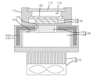
- FIG. 1 is a cross-sectional view of an image capture apparatus according to one embodiment of the present invention.
- an image capture apparatus includes an image sensor 120 , a cooler 130 , and a moving device 150 .
- the image sensor 120 is mounted on a printed circuit board (not shown).
- the image sensor 120 may be attached to one surface of the printed circuit board.
- the image sensor 120 may be placed on a circumference of the opening. In this way, the image sensor 120 may be mounted on the printed circuit board in various forms.
- Circuit wiring of the image sensor 120 and circuit wiring of the printed circuit board are connected to each other.
- the printed circuit board is connected to a controller (not shown) of the image capture apparatus. Information about an image photographed by the image sensor 120 is transmitted to the controller through the printed circuit board.
- the cooler 130 is places at one side (a lower side in FIG. 1 ) of the image sensor 120 and cools the image sensor 120 .
- the cooler 130 may be applied in various forms so long as the cooler can cool the image sensor 120 .
- one embodiment of the cooler 130 will be described by way of example.
- the cooler 130 may be a thermoelectric module, such as a Peltier element, which includes a cooling portion 131 and a heating portion 133 .
- a thermoelectric module such as a Peltier element
- DC direct current
- one side of the thermoelectric module is cooled and the other side of the thermoelectric module generates heat.
- the thermoelectric module advantageously allows selective cooling of a necessary portion.
- the one side (an upper side in FIG. 1 ) of the thermoelectric module will be defined as the cooling portion 131
- the other side (a lower side in FIG. 1 ) of the thermoelectric module will be defined as the heating portion 133 .
- the cooling portion 131 of the thermoelectric module is placed at one side of the image sensor 120 and cools the image sensor 120 when the image sensor 120 generates heat.
- the cooling portion 131 may directly contact the image sensor 120 or indirectly contact the image sensor 120 via a thermally conductive medium.
- the thermal-conductive medium may be a metal or an alloy having good thermal conductivity, or a thermal-conductive fluid, such as grease.
- the expression “contact between the cooling portion 131 and the image sensor 120 ” means both direct contact and indirect conduct therebetween.
- the image sensor 120 can reduce dark current noise.
- the dark current noise refers to a signal value of a thermion generated by heat from the image sensor 120 even though no light enters the image sensor 120 .
- the dark current noise decreases a dynamic range of the image sensor 120 , thereby deteriorating performance of the image capture apparatus.
- the dynamic range refers to a ratio of brightest region to darkest region in an image, and is an index indicating capabilities of including both dark and bright regions in one image.
- the image sensor 120 and the cooler 130 are placed inside a first housing 110 .
- the first housing 110 is formed with an accommodating space 113 to accommodate the image sensor 120 and the cooler 130 therein.
- the cooling portion 131 of the cooler 130 is disposed to contact the image sensor 120 .
- the heating portion 133 of the cooler 130 may directly contact a bottom of the first housing 110 or indirectly contact the bottom of the first housing 110 via a thermally conductive medium.
- contact between the heating portion 133 and the first housing 110 means both direct contact and indirect conduct therebetween.
- the first housing 110 may be made of a thermally conductive material so as to dissipate heat of the heating portion 133 .
- the thermally conductive material may form the entirety or only part of the first housing 110 .
- the heating portion 133 has a large heat dissipation area.
- the cooling portion 131 also has improved cooling performance.
- the improved heat dissipating performance of the heating portion 133 enhances not only cooling performance of the cooling portion 131 , but also efficiency of cooling the image sensor 120 .
- the first housing 110 is provided with a stationary glass plate 115 to receive incident light.
- the glass plate 115 prevents foreign matter from being introduced into the first housing 110 , thereby preventing the image sensor 120 from being contaminated by foreign matter.
- the moving device 150 is placed at one side (the lower side in FIG. 1 ) of the cooler 130 .
- the moving device 150 moves the image sensor 120 and the cooler 130 .
- the moving device 150 moves the first housing 110 to move the image sensor 120 and the cooler 130 received in the first housing 110 .
- the moving device 150 includes a coupler 151 and a drive unit 153 .
- the coupler 151 is a medium for transferring driving force of the drive unit 153 to the cooler 130 and the image sensor 120 .
- the coupler 151 is connected to one side of the first housing 110 .
- one surface of the coupler 151 may be coupled to one surface of the first housing 110 by an adhesive or a fastening member.
- the drive unit 153 is coupled to the coupler 151 and moves the coupler 151 by driving force.
- the drive unit 153 moves the first housing 110 in units of 1/n pixels, whereby the image sensor 120 can be very minutely moved in units of 1/n pixels.
- the image sensor 120 can capture an image while moving in units of 1/n pixels along X and Y axes, and combines a plurality of captured images through software, thereby providing one final image.
- n refers to the number of moving times required to move the image sensor 120 as much as a length of one pixel, assuming that one pixel has a length of 1.
- the drive unit 153 may move the image sensor 120 in units of 0.5 pixels.
- the image sensor 120 captures images while moving, and the controller combines the captured images and outputs a combined image, thereby improving resolution of the output final image. This operation will be described in more detail hereinafter.
- the drive unit 153 moves the coupler 151 along two axes.
- the drive unit 153 moves the coupler 151 in directions of X and Y axes. Therefore, the image sensor 120 can move in units of 1/n pixels along the X and Y axes.
- the drive unit 153 may include a plurality of piezoelectric elements connected to the coupler 151 .
- the piezoelectric elements When voltage is applied to the piezoelectric elements, the piezoelectric elements are changed in shape, and thus, the coupler 151 and the image sensor 120 are moved.
- the drive unit 153 may have a structure in which four panels are stacked one above another and one panel is moved by the piezoelectric element.
- the drive unit 153 may have any structure so long as it can move the image sensor 120 .
- the drive unit 153 is a nano-stage which extremely minutely moves the image sensor 120 .
- the image capture apparatus further includes a heat dissipating portion 160 connected to the heating portion 133 of the cooler 130 and cooling the heating portion 133 .
- the heat dissipating portion 160 may directly contact the heating portion 133 or indirectly contact the heating portion 133 via a thermally conductive medium.
- the heat dissipating portion 160 may be a heat pipe, in which a thermally conductive fluid flows inside a pipe body (not shown). The heat pipe quickly dissipates heat of the heating portion 133 through heat exchange by the flow of the thermally conductive fluid.
- the heat pipe can dissipate heat to the outside while minimizing difference in temperature between the heating portion 133 and the cooling unit. Therefore, improved heat dissipating performance of the heating portion 133 enhances cooling performance of the cooling portion 131 , thereby improving efficiency of cooling the image sensor 120 .
- the heat dissipating portion 160 may be placed in the second housing 140 .
- the heat dissipating portion 160 may be formed in various shapes, such as an I-shape, L-shape, and the like, in the second housing 140 .
- the second housing 140 adjoins one surface of the first housing 110 .
- the one surface of the second housing 140 may be smooth such that one surface of the first housing 110 can smoothly slide thereon.
- Grease may be provided to the one surface of second housing 140 so as to allow the first housing 110 to smoothly slide and to improve efficiency of heat exchange.
- the moving device 150 is placed in an inner space 143 of the second housing 140 .
- the second housing 140 is formed with an opening 145 through which the coupler 151 can be inserted.
- the opening 145 is larger than the coupler 151 such that the coupler 151 can be moved by the drive unit 153 .
- the second housing 140 is made of a thermally conductive material so as to dissipate heat of the heat dissipating portion 160 .
- the thermally conductive material may form the entirety or only part of the second housing 140 . In this way, since the heating portion 133 is connected to the second housing 140 through the first housing 110 , the heat dissipation area of the heating portion 133 is further increased by the second housing 140 . Therefore, performance for cooling the image sensor 120 is also further improved.
- the image capture apparatus may further include a heat sink 170 , which contacts the second housing 140 and cools the second housing 140 .
- the heat sink 170 includes heat exchange fins 171 contacting the second housing 140 , and a fan 173 to blow air to the heat exchange fins 171 .
- the heat exchange fins 171 increase the heat dissipation area of the second housing 140 , and the fan 173 causes forced convection, thereby achieving more effective heat dissipation.
- the heat exchange fins 171 may be formed in various shapes. Since the heat sink 170 improves heat dissipation of the second housing 140 , performance of cooling the image sensor 120 is further enhanced.
- the image sensor will be illustrated as moving in units of 0.5 pixels.
- FIG. 2 shows an object image and a pixel array of the image capture apparatus of FIG. 1
- FIG. 3 shows a photographing method of the image capture apparatus of FIG. 1 .
- an image 10 of an object is projected on a pixel array 20 .
- the moving device 150 allows the image capture apparatus to capture the image while moving the pixel array 20 , which will be described below in detail.
- the image sensor 120 is moved in a direction of the X axis (a rightward direction in FIG. 3 ) as much as 0.5 pixels. At this position, the image sensor 120 captures an image of the object (i.e., image A (the uppermost image) in FIG. 3 ). A photographed first output image 30 is stored in a storage (not shown).
- the image sensor 120 is moved in a diagonal direction. At this time, the image sensor 120 is moved along the X axis as much as 0.5 pixels and is moved along the Y axis as much as 0.5 pixels, resulting in movement in the diagonal direction (a direction toward a left lower side in FIG. 3 ). At this position, the image sensor 120 captures an image of the object (i.e., image B (the second image from the top) in FIG. 3 ). A photographed second output image 31 is stored in the storage.
- image B the second image from the top
- the image sensor 120 is moved in a direction of the X axis (the rightward direction in FIG. 3 ) as much as 0.5 pixels. At this position, the image sensor 120 captures an image of the object (i.e., image C (the third image from the top) in FIG. 3 ). A photographed third output image 32 is stored in a storage.
- the image sensor 120 is moved in a diagonal direction. At this time, the image sensor 120 is moved along the X axis as much as 0.5 pixels and is moved along the Y axis as much as 0.5 pixels, resulting in movement in the diagonal direction (a direction toward a left upper side in FIG. 3 ). At this position, the image sensor 120 captures an image of the object (i.e., image D (the fourth image from the top) in FIG. 3 ). A photographed fourth output image 33 is stored in the storage.
- the controller combines the first to fourth output images 30 , 31 , 32 , 33 and outputs a final image 40 .
- the final image 40 is an image finally obtained by combining the four output images 30 , 31 , 32 , 33 , which has a higher resolution than a final image 50 based only on a single output image. Therefore, the image capture apparatus has improved resolution.
- the image sensor 120 can generate heat while the image capture apparatus captures an image. At this time, the cooling portion 131 cools the image sensor 120 , thereby minimizing emission of thermions from the image sensor 120 . Thus, the image sensor 120 can be prevented from generating dark current noise, thereby improving the resolution of the image capture apparatus.
- the heating portion 133 is directly and indirectly connected to the first housing 110 and the second housing 140 and thus has an increased heat dissipation area.
- the heating portion 133 may dissipate heat through the heat dissipating portion 160 .
- the first housing 110 , the second housing 140 and the heat dissipating portion 160 improve heat dissipation of the heating portion 133 , thereby improving performance of the cooling portion 131 in the cooler 130 .
- the first housing 110 , the second housing 140 and the heat dissipating portion 160 also enhance performance of cooling the image sensor 120 , thereby minimizing emission of thermions from the image sensor 120 .
- the image capture apparatus captures an image while cooling the image sensor 120 and moving the pixel array 20 , thereby providing a high resolution.
Landscapes
- Engineering & Computer Science (AREA)
- Multimedia (AREA)
- Signal Processing (AREA)
- Computing Systems (AREA)
- Theoretical Computer Science (AREA)
- Physics & Mathematics (AREA)
- Electromagnetism (AREA)
- Studio Devices (AREA)
- Transforming Light Signals Into Electric Signals (AREA)
- Solid State Image Pick-Up Elements (AREA)
- Chemical & Material Sciences (AREA)
- Materials Engineering (AREA)
Abstract
Description
- 1. Technical Field
- The present invention relates to an image capture apparatus, and more particularly, to an image capture apparatus which can achieve a high resolution and reduce noise of an image sensor.
- 2. Description of the Related Art
- In general, an image capture apparatus refers to an apparatus for photographing an object. The image capture apparatus is applicable to inspection devices, imaging devices, communication devices, and various similar devices. For example, the image capture apparatus may be applied to an inspection device for displays, an inspection device for semiconductor devices, an inspection device for printed circuit boards, an inspection device for solar panels, etc. The image capture apparatus photographs an inspection target, and an inspection device reads the photographed image and determines whether the target is defective.
- A background technique of the present invention is disclosed in Korean Patent Publication No. 2006-0045565, published on May 17, 2006 and entitled “Lens barrel combining apparatus for camera module and combining method using the same.”
- A typical image capture apparatus photographs an object with an image sensor placed in a stationary state, it is difficult to capture an image having a higher resolution than the resolution of the image sensor in the image capture apparatus. In addition, since the image sensor generates heat and makes noise, there can be a problem of deterioration in image quality in the case of products required to make less noise. Therefore, there is a need for an image capture apparatus that overcomes such problems.
- The present invention is conceived to solve such problems in the related art, and an aspect of the present invention is to provide an image capture apparatus, which can capture an image having a higher resolution than that that of an image sensor and can reduce noise of the image sensor.
- In accordance with one aspect of the present invention, an image capture apparatus includes: an image sensor; a cooler placed at one side of the image sensor and cooling the image sensor; and a moving device placed at one side of the cooler and moving the image sensor and the cooler.
- The cooler may include a thermoelectric module including a cooling portion and a heating portion, and the cooling portion may be placed at the one side of the image sensor.
- The cooling portion may contact the image sensor and cool the image sensor.
- The image capture apparatus may further include a heat dissipating portion placed at one side of the heating portion and cooling the heating portion.
- The heat dissipating portion may include a heat pipe.
- The moving device may include a coupler placed at one side of the thermoelectric module; and a drive unit coupled to the coupler and moving the coupler.
- The drive unit may move the image sensor in units of 1/n pixels, where n refers to the number of moving times required to move the image sensor as much as a length of one pixel, assuming that one pixel has a length of 1.
- In accordance with another aspect of the present invention, an image capture apparatus includes: a first housing; an image sensor received in the first housing; a cooler placed at one side of the image sensor and cooling the image sensor; a second housing adjoining the first housing; and a moving device placed inside the second housing and connected to the first housing to move the first housing.
- The cooler may include a thermoelectric module including a cooling portion and a heating portion, and the cooling portion may be placed at the one side of the image sensor.
- The cooling portion may contact the image sensor and cool the image sensor, and the heating portion may contact the first housing.
- The image capture apparatus may further include a heat dissipating portion placed in the second housing and cooling the heating portion.
- The heat dissipating portion may include a heat pipe.
- The moving device may include: a coupler connected to the first housing; and a drive unit placed inside the second housing, and coupled to the coupler and moving the coupler.
- The drive unit may move the image sensor in units of 1/n pixels, where n refers to the number of moving times required to move the image sensor as much as a length of one pixel, assuming that one pixel has a length of 1.
- The image capture apparatus may further include a heat sink that contacts the second housing and cools the second housing.
- According to the present invention, the image capture apparatus can capture an image while cooling an image sensor and moving a pixel array, thereby providing a high resolution while reducing noise of the image sensor.
- The above and other aspects, features and advantages of the present invention will become apparent from the following description of embodiments given in conjunction with the accompanying drawings, in which:
-
FIG. 1 is a cross-sectional view of an image capture apparatus according to one embodiment of the present invention; -
FIG. 2 shows an object image and a pixel array of the image capture apparatus ofFIG. 1 ; and -
FIG. 3 shows a photographing method of the image capture apparatus ofFIG. 1 . - Hereinafter, embodiments of the present invention will now be described in detail with reference to the accompanying drawings. It should be noted that the drawings are not to precise scale and may be exaggerated in thickness of lines or size of components for descriptive convenience and clarity only. Furthermore, the terms used herein are defined by taking functions of the present invention into account and can be changed according to user or operator's custom or intention. Therefore, definition of the terms should be made according to the overall disclosure set forth herein.
-
FIG. 1 is a cross-sectional view of an image capture apparatus according to one embodiment of the present invention. - Referring to
FIG. 1 , an image capture apparatus according to one embodiment of the present invention includes animage sensor 120, acooler 130, and a moving device 150. - The
image sensor 120 is mounted on a printed circuit board (not shown). Here, theimage sensor 120 may be attached to one surface of the printed circuit board. In addition, when the printed circuit board is formed with an opening, theimage sensor 120 may be placed on a circumference of the opening. In this way, theimage sensor 120 may be mounted on the printed circuit board in various forms. - Circuit wiring of the
image sensor 120 and circuit wiring of the printed circuit board are connected to each other. The printed circuit board is connected to a controller (not shown) of the image capture apparatus. Information about an image photographed by theimage sensor 120 is transmitted to the controller through the printed circuit board. - The
cooler 130 is places at one side (a lower side inFIG. 1 ) of theimage sensor 120 and cools theimage sensor 120. Thecooler 130 may be applied in various forms so long as the cooler can cool theimage sensor 120. Hereinafter, one embodiment of thecooler 130 will be described by way of example. - The
cooler 130 may be a thermoelectric module, such as a Peltier element, which includes a cooling portion 131 and aheating portion 133. When direct current (DC) voltage is applied to opposite ends of two different elements that constitute the thermoelectric module, one side of the thermoelectric module is cooled and the other side of the thermoelectric module generates heat. Thus, in use, the thermoelectric module advantageously allows selective cooling of a necessary portion. In this embodiment, the one side (an upper side inFIG. 1 ) of the thermoelectric module will be defined as the cooling portion 131, and the other side (a lower side inFIG. 1 ) of the thermoelectric module will be defined as theheating portion 133. - The cooling portion 131 of the thermoelectric module is placed at one side of the
image sensor 120 and cools theimage sensor 120 when theimage sensor 120 generates heat. The cooling portion 131 may directly contact theimage sensor 120 or indirectly contact theimage sensor 120 via a thermally conductive medium. Here, the thermal-conductive medium may be a metal or an alloy having good thermal conductivity, or a thermal-conductive fluid, such as grease. As such, the expression “contact between the cooling portion 131 and theimage sensor 120” means both direct contact and indirect conduct therebetween. - Since the
image sensor 120 is cooled by thecooler 130, theimage sensor 120 can reduce dark current noise. The dark current noise refers to a signal value of a thermion generated by heat from theimage sensor 120 even though no light enters theimage sensor 120. The dark current noise decreases a dynamic range of theimage sensor 120, thereby deteriorating performance of the image capture apparatus. The dynamic range refers to a ratio of brightest region to darkest region in an image, and is an index indicating capabilities of including both dark and bright regions in one image. - The
image sensor 120 and the cooler 130 are placed inside afirst housing 110. Thefirst housing 110 is formed with anaccommodating space 113 to accommodate theimage sensor 120 and the cooler 130 therein. Here, the cooling portion 131 of the cooler 130 is disposed to contact theimage sensor 120. - In addition, the
heating portion 133 of the cooler 130 may directly contact a bottom of thefirst housing 110 or indirectly contact the bottom of thefirst housing 110 via a thermally conductive medium. Here, contact between theheating portion 133 and thefirst housing 110 means both direct contact and indirect conduct therebetween. - The
first housing 110 may be made of a thermally conductive material so as to dissipate heat of theheating portion 133. The thermally conductive material may form the entirety or only part of thefirst housing 110. In this way, since thefirst housing 110 is made of the thermally conductive material, theheating portion 133 has a large heat dissipation area. As theheating portion 133 has improved heat dissipating performance, the cooling portion 131 also has improved cooling performance. Further, since heat generated from theimage sensor 120 is transferred to the cooling portion 131 and discharged outside through theheating portion 133, the improved heat dissipating performance of theheating portion 133 enhances not only cooling performance of the cooling portion 131, but also efficiency of cooling theimage sensor 120. - The
first housing 110 is provided with astationary glass plate 115 to receive incident light. Theglass plate 115 prevents foreign matter from being introduced into thefirst housing 110, thereby preventing theimage sensor 120 from being contaminated by foreign matter. - The moving device 150 is placed at one side (the lower side in
FIG. 1 ) of the cooler 130. The moving device 150 moves theimage sensor 120 and the cooler 130. In this embodiment, the moving device 150 moves thefirst housing 110 to move theimage sensor 120 and the cooler 130 received in thefirst housing 110. The moving device 150 includes a coupler 151 and a drive unit 153. - The coupler 151 is a medium for transferring driving force of the drive unit 153 to the cooler 130 and the
image sensor 120. The coupler 151 is connected to one side of thefirst housing 110. Here, one surface of the coupler 151 may be coupled to one surface of thefirst housing 110 by an adhesive or a fastening member. - The drive unit 153 is coupled to the coupler 151 and moves the coupler 151 by driving force. The drive unit 153 moves the
first housing 110 in units of 1/n pixels, whereby theimage sensor 120 can be very minutely moved in units of 1/n pixels. Thus, theimage sensor 120 can capture an image while moving in units of 1/n pixels along X and Y axes, and combines a plurality of captured images through software, thereby providing one final image. - Herein, n refers to the number of moving times required to move the
image sensor 120 as much as a length of one pixel, assuming that one pixel has a length of 1. For example, inFIG. 3 , the drive unit 153 may move theimage sensor 120 in units of 0.5 pixels. Theimage sensor 120 captures images while moving, and the controller combines the captured images and outputs a combined image, thereby improving resolution of the output final image. This operation will be described in more detail hereinafter. - The drive unit 153 moves the coupler 151 along two axes. For example, the drive unit 153 moves the coupler 151 in directions of X and Y axes. Therefore, the
image sensor 120 can move in units of 1/n pixels along the X and Y axes. - The drive unit 153 may include a plurality of piezoelectric elements connected to the coupler 151. When voltage is applied to the piezoelectric elements, the piezoelectric elements are changed in shape, and thus, the coupler 151 and the
image sensor 120 are moved. - The drive unit 153 may have a structure in which four panels are stacked one above another and one panel is moved by the piezoelectric element. The drive unit 153 may have any structure so long as it can move the
image sensor 120. The drive unit 153 is a nano-stage which extremely minutely moves theimage sensor 120. - In this embodiment, the image capture apparatus further includes a
heat dissipating portion 160 connected to theheating portion 133 of the cooler 130 and cooling theheating portion 133. Theheat dissipating portion 160 may directly contact theheating portion 133 or indirectly contact theheating portion 133 via a thermally conductive medium. Theheat dissipating portion 160 may be a heat pipe, in which a thermally conductive fluid flows inside a pipe body (not shown). The heat pipe quickly dissipates heat of theheating portion 133 through heat exchange by the flow of the thermally conductive fluid. As such, when there is a long distance or an obstacle between theheating portion 133 and a cooling unit for cooling theheating portion 133, the heat pipe can dissipate heat to the outside while minimizing difference in temperature between theheating portion 133 and the cooling unit. Therefore, improved heat dissipating performance of theheating portion 133 enhances cooling performance of the cooling portion 131, thereby improving efficiency of cooling theimage sensor 120. - The
heat dissipating portion 160 may be placed in thesecond housing 140. Theheat dissipating portion 160 may be formed in various shapes, such as an I-shape, L-shape, and the like, in thesecond housing 140. - The
second housing 140 adjoins one surface of thefirst housing 110. The one surface of thesecond housing 140 may be smooth such that one surface of thefirst housing 110 can smoothly slide thereon. Grease may be provided to the one surface ofsecond housing 140 so as to allow thefirst housing 110 to smoothly slide and to improve efficiency of heat exchange. - The moving device 150 is placed in an
inner space 143 of thesecond housing 140. Thesecond housing 140 is formed with anopening 145 through which the coupler 151 can be inserted. Theopening 145 is larger than the coupler 151 such that the coupler 151 can be moved by the drive unit 153. - The
second housing 140 is made of a thermally conductive material so as to dissipate heat of theheat dissipating portion 160. The thermally conductive material may form the entirety or only part of thesecond housing 140. In this way, since theheating portion 133 is connected to thesecond housing 140 through thefirst housing 110, the heat dissipation area of theheating portion 133 is further increased by thesecond housing 140. Therefore, performance for cooling theimage sensor 120 is also further improved. - In this embodiment, the image capture apparatus may further include a
heat sink 170, which contacts thesecond housing 140 and cools thesecond housing 140. Theheat sink 170 includesheat exchange fins 171 contacting thesecond housing 140, and afan 173 to blow air to theheat exchange fins 171. Theheat exchange fins 171 increase the heat dissipation area of thesecond housing 140, and thefan 173 causes forced convection, thereby achieving more effective heat dissipation. Theheat exchange fins 171 may be formed in various shapes. Since theheat sink 170 improves heat dissipation of thesecond housing 140, performance of cooling theimage sensor 120 is further enhanced. - Next, operation of the image capture apparatus with the foregoing configuration according to the embodiment of the invention will be described hereinafter. In the following description, the image sensor will be illustrated as moving in units of 0.5 pixels.
-
FIG. 2 shows an object image and a pixel array of the image capture apparatus ofFIG. 1 , andFIG. 3 shows a photographing method of the image capture apparatus ofFIG. 1 . - Referring to
FIGS. 2 and 3 , animage 10 of an object is projected on apixel array 20. The moving device 150 allows the image capture apparatus to capture the image while moving thepixel array 20, which will be described below in detail. - As the moving device 150 is operated, the
image sensor 120 is moved in a direction of the X axis (a rightward direction inFIG. 3 ) as much as 0.5 pixels. At this position, theimage sensor 120 captures an image of the object (i.e., image A (the uppermost image) inFIG. 3 ). A photographedfirst output image 30 is stored in a storage (not shown). - As the moving device 150 is operated, the
image sensor 120 is moved in a diagonal direction. At this time, theimage sensor 120 is moved along the X axis as much as 0.5 pixels and is moved along the Y axis as much as 0.5 pixels, resulting in movement in the diagonal direction (a direction toward a left lower side inFIG. 3 ). At this position, theimage sensor 120 captures an image of the object (i.e., image B (the second image from the top) inFIG. 3 ). A photographedsecond output image 31 is stored in the storage. - As the moving device 150 is operated, the
image sensor 120 is moved in a direction of the X axis (the rightward direction inFIG. 3 ) as much as 0.5 pixels. At this position, theimage sensor 120 captures an image of the object (i.e., image C (the third image from the top) inFIG. 3 ). A photographedthird output image 32 is stored in a storage. - As the moving device 150 is operated, the
image sensor 120 is moved in a diagonal direction. At this time, theimage sensor 120 is moved along the X axis as much as 0.5 pixels and is moved along the Y axis as much as 0.5 pixels, resulting in movement in the diagonal direction (a direction toward a left upper side inFIG. 3 ). At this position, theimage sensor 120 captures an image of the object (i.e., image D (the fourth image from the top) inFIG. 3 ). A photographedfourth output image 33 is stored in the storage. - The controller combines the first to
fourth output images final image 40. Thefinal image 40 is an image finally obtained by combining the fouroutput images final image 50 based only on a single output image. Therefore, the image capture apparatus has improved resolution. - The
image sensor 120 can generate heat while the image capture apparatus captures an image. At this time, the cooling portion 131 cools theimage sensor 120, thereby minimizing emission of thermions from theimage sensor 120. Thus, theimage sensor 120 can be prevented from generating dark current noise, thereby improving the resolution of the image capture apparatus. - The
heating portion 133 is directly and indirectly connected to thefirst housing 110 and thesecond housing 140 and thus has an increased heat dissipation area. In addition, theheating portion 133 may dissipate heat through theheat dissipating portion 160. In this way, thefirst housing 110, thesecond housing 140 and theheat dissipating portion 160 improve heat dissipation of theheating portion 133, thereby improving performance of the cooling portion 131 in the cooler 130. As a result, thefirst housing 110, thesecond housing 140 and theheat dissipating portion 160 also enhance performance of cooling theimage sensor 120, thereby minimizing emission of thermions from theimage sensor 120. - As such, the image capture apparatus captures an image while cooling the
image sensor 120 and moving thepixel array 20, thereby providing a high resolution. - Although some embodiments have been described herein, it should be understood that these embodiments are given by way of illustration only, and that various modifications, variations, and alterations can be made without departing from the spirit and scope of the present invention. The scope of the present invention should be limited only by the accompanying claims and equivalents thereof.
Claims (15)
Applications Claiming Priority (3)
| Application Number | Priority Date | Filing Date | Title |
|---|---|---|---|
| KR10-2013-0047326 | 2013-04-29 | ||
| KR1020130047326A KR101391176B1 (en) | 2013-04-29 | 2013-04-29 | Image photography apparatus |
| PCT/KR2014/002717 WO2014178539A1 (en) | 2013-04-29 | 2014-03-31 | Image photographing apparatus |
Publications (2)
| Publication Number | Publication Date |
|---|---|
| US20150358564A1 true US20150358564A1 (en) | 2015-12-10 |
| US9628731B2 US9628731B2 (en) | 2017-04-18 |
Family
ID=50892999
Family Applications (1)
| Application Number | Title | Priority Date | Filing Date |
|---|---|---|---|
| US14/761,528 Active US9628731B2 (en) | 2013-04-29 | 2014-03-31 | Image capture apparatus |
Country Status (7)
| Country | Link |
|---|---|
| US (1) | US9628731B2 (en) |
| EP (1) | EP2993885B1 (en) |
| JP (1) | JP2016502371A (en) |
| KR (1) | KR101391176B1 (en) |
| CN (1) | CN104956658B (en) |
| TW (1) | TWI548271B (en) |
| WO (1) | WO2014178539A1 (en) |
Cited By (10)
| Publication number | Priority date | Publication date | Assignee | Title |
|---|---|---|---|---|
| US20160307953A1 (en) * | 2015-04-16 | 2016-10-20 | Denso Corporation | Imaging device and circuit board therefor |
| EP3163864A4 (en) * | 2014-06-26 | 2018-02-14 | Kyocera Corporation | Image-capturing device and vehicle |
| US20190293544A1 (en) * | 2016-11-24 | 2019-09-26 | Commissariat A L'energie Atomique Et Aux Energies Alternatives | Method for forming a high resolution image by lensless imaging |
| US10701249B1 (en) * | 2019-04-28 | 2020-06-30 | SZ DJI Technology Co., Ltd. | Heat dissipation assembly and action camera |
| US10944892B2 (en) * | 2017-03-20 | 2021-03-09 | Rosenberger Hochfrequenztechnik Gmbh | Housing part for a camera housing |
| US10951794B2 (en) * | 2018-10-11 | 2021-03-16 | Rakuten, Inc. | Camera assembly |
| US20220159158A1 (en) * | 2020-11-16 | 2022-05-19 | Samsung Electro-Mechanics Co., Ltd. | Camera module |
| US20220240414A1 (en) * | 2021-01-27 | 2022-07-28 | Panasonic Intellectual Property Management Co., Ltd. | Imaging device |
| US20220294957A1 (en) * | 2021-03-09 | 2022-09-15 | Canon Kabushiki Kaisha | Image pickup apparatus |
| JP2024100731A (en) * | 2023-01-16 | 2024-07-26 | ビューワークス カンパニー リミテッド | Video shooting device |
Families Citing this family (13)
| Publication number | Priority date | Publication date | Assignee | Title |
|---|---|---|---|---|
| FR2820064B1 (en) * | 2001-01-30 | 2003-05-16 | Pronic | TAPPING UNIT |
| TWI533274B (en) * | 2015-04-17 | 2016-05-11 | 友達光電股份有限公司 | Display panel |
| US9628735B2 (en) * | 2015-06-22 | 2017-04-18 | Omnivision Technologies, Inc. | Imaging systems with single-photon-avalanche-diodes and sensor translation, and associated methods |
| WO2018061881A1 (en) * | 2016-09-28 | 2018-04-05 | 京セラ株式会社 | Camera module |
| EP3471391B1 (en) * | 2017-10-10 | 2020-08-12 | Axis AB | A camera |
| US10638643B2 (en) * | 2017-11-14 | 2020-04-28 | Canon Kabushiki Kaisha | Electronic device |
| KR102264500B1 (en) * | 2019-01-18 | 2021-06-14 | 김인균 | Camera assembly for vision inspection having means for keeping the operating temperature of the imaging device constant |
| KR102230492B1 (en) * | 2019-10-01 | 2021-03-22 | 주식회사 뷰웍스 | Imaging device |
| CN212163453U (en) * | 2020-04-08 | 2020-12-15 | 华为技术有限公司 | Image sensing module, camera module, terminal equipment and mold |
| KR102455183B1 (en) * | 2021-01-12 | 2022-10-17 | 주식회사 뷰웍스 | Image sensor assembly |
| KR20240122328A (en) | 2023-02-03 | 2024-08-12 | 주식회사 뷰웍스 | Image photographing apparatus |
| KR102868904B1 (en) | 2023-04-05 | 2025-10-14 | 주식회사 뷰웍스 | Cooling structure of camera and camera having the same |
| KR102868905B1 (en) | 2024-01-04 | 2025-10-14 | 주식회사 뷰웍스 | Industrial camera |
Citations (3)
| Publication number | Priority date | Publication date | Assignee | Title |
|---|---|---|---|---|
| US6307590B1 (en) * | 1997-01-30 | 2001-10-23 | Fuji Photo Film Co., Ltd. | Cooled CCD camera |
| US20040075870A1 (en) * | 2002-09-27 | 2004-04-22 | Olympus Optical Co., Ltd. | Imaging apparatus |
| US20140055671A1 (en) * | 2012-08-27 | 2014-02-27 | Canon Kabushiki Kaisha | Image pickup apparatus with air cooling unit |
Family Cites Families (19)
| Publication number | Priority date | Publication date | Assignee | Title |
|---|---|---|---|---|
| US5213152A (en) | 1991-11-05 | 1993-05-25 | Abb Air Preheater, Inc. | Temperature control system for a heat detector on a heat exchanger |
| US5453618A (en) | 1994-01-31 | 1995-09-26 | Litton Systems, Inc. | Miniature infrared line-scanning imager |
| JPH08107526A (en) * | 1994-10-05 | 1996-04-23 | Olympus Optical Co Ltd | Electronic imager |
| JPH08251604A (en) * | 1995-03-08 | 1996-09-27 | Sony Corp | Solid color imaging device |
| DE69819597T2 (en) * | 1997-05-22 | 2004-09-23 | Sanyo Electric Co., Ltd., Moriguchi | Power supply circuit and CCD camera using it |
| JP4307602B2 (en) * | 1998-11-24 | 2009-08-05 | オリンパス株式会社 | Imaging apparatus and operation mode setting method of imaging apparatus |
| TW497234B (en) * | 2000-03-29 | 2002-08-01 | Omnivision Tech Inc | Image sensor integrate circuit package having cooling |
| JP2002162207A (en) * | 2000-11-24 | 2002-06-07 | Mitsubishi Heavy Ind Ltd | Image processing method, image processing apparatus, and image capturing analysis system |
| KR100625855B1 (en) | 2004-10-25 | 2006-09-20 | (주) 에스에스피 | Lens barrel combining apparatus for camera module and combining method using the same |
| JP2006174226A (en) * | 2004-12-17 | 2006-06-29 | Konica Minolta Photo Imaging Inc | Imaging unit and imaging apparatus |
| KR20060071159A (en) | 2004-12-21 | 2006-06-26 | 주식회사 대우일렉트로닉스 | Cooling device of television |
| US7884861B2 (en) * | 2005-03-22 | 2011-02-08 | Microview Technologies PTD Ltd. | Image resolution multiplier |
| JP4788589B2 (en) * | 2006-12-13 | 2011-10-05 | カシオ計算機株式会社 | Imaging device |
| JP2008187264A (en) * | 2007-01-26 | 2008-08-14 | Nikon Corp | Cooled imaging device |
| KR20080073072A (en) * | 2007-02-05 | 2008-08-08 | 엘지이노텍 주식회사 | Camera module with heat dissipation means |
| JP2008219610A (en) * | 2007-03-06 | 2008-09-18 | Nikon Corp | Image sensor cooled camera |
| JP2008271487A (en) * | 2007-03-29 | 2008-11-06 | Olympus Imaging Corp | Imaging device module, lens unit using imaging device module, and portable electronic device |
| TWI390967B (en) * | 2009-03-16 | 2013-03-21 | 華晶科技股份有限公司 | Method for turning off timing generating unit, method for turning off digital image capturing device and digital image capturing device |
| JP5896650B2 (en) * | 2011-08-31 | 2016-03-30 | オリンパス株式会社 | Imaging device |
-
2013
- 2013-04-29 KR KR1020130047326A patent/KR101391176B1/en active Active
-
2014
- 2014-03-31 US US14/761,528 patent/US9628731B2/en active Active
- 2014-03-31 EP EP14791635.7A patent/EP2993885B1/en active Active
- 2014-03-31 CN CN201480006691.4A patent/CN104956658B/en active Active
- 2014-03-31 JP JP2015550341A patent/JP2016502371A/en active Pending
- 2014-03-31 WO PCT/KR2014/002717 patent/WO2014178539A1/en not_active Ceased
- 2014-04-15 TW TW103113634A patent/TWI548271B/en active
Patent Citations (3)
| Publication number | Priority date | Publication date | Assignee | Title |
|---|---|---|---|---|
| US6307590B1 (en) * | 1997-01-30 | 2001-10-23 | Fuji Photo Film Co., Ltd. | Cooled CCD camera |
| US20040075870A1 (en) * | 2002-09-27 | 2004-04-22 | Olympus Optical Co., Ltd. | Imaging apparatus |
| US20140055671A1 (en) * | 2012-08-27 | 2014-02-27 | Canon Kabushiki Kaisha | Image pickup apparatus with air cooling unit |
Cited By (18)
| Publication number | Priority date | Publication date | Assignee | Title |
|---|---|---|---|---|
| EP3163864A4 (en) * | 2014-06-26 | 2018-02-14 | Kyocera Corporation | Image-capturing device and vehicle |
| US10766431B2 (en) | 2014-06-26 | 2020-09-08 | Kyocera Corporation | Imaging apparatus and vehicle |
| US9669772B2 (en) * | 2015-04-16 | 2017-06-06 | Denso Corporation | Imaging device and circuit board therefor |
| US20160307953A1 (en) * | 2015-04-16 | 2016-10-20 | Denso Corporation | Imaging device and circuit board therefor |
| US10989648B2 (en) * | 2016-11-24 | 2021-04-27 | Commissariat A L'energie Atomique Et Aux Energies Alternatives | Method for forming a high resolution image by lensless imaging |
| US20190293544A1 (en) * | 2016-11-24 | 2019-09-26 | Commissariat A L'energie Atomique Et Aux Energies Alternatives | Method for forming a high resolution image by lensless imaging |
| US10944892B2 (en) * | 2017-03-20 | 2021-03-09 | Rosenberger Hochfrequenztechnik Gmbh | Housing part for a camera housing |
| US10951794B2 (en) * | 2018-10-11 | 2021-03-16 | Rakuten, Inc. | Camera assembly |
| US10701249B1 (en) * | 2019-04-28 | 2020-06-30 | SZ DJI Technology Co., Ltd. | Heat dissipation assembly and action camera |
| US11303784B2 (en) | 2019-04-28 | 2022-04-12 | SZ DJI Technology Co., Ltd. | Heat dissipation assembly and action camera |
| US20220159158A1 (en) * | 2020-11-16 | 2022-05-19 | Samsung Electro-Mechanics Co., Ltd. | Camera module |
| US11683576B2 (en) * | 2020-11-16 | 2023-06-20 | Samsung Electro-Mechanics Co., Ltd. | Camera module |
| US20220240414A1 (en) * | 2021-01-27 | 2022-07-28 | Panasonic Intellectual Property Management Co., Ltd. | Imaging device |
| US11936966B2 (en) * | 2021-01-27 | 2024-03-19 | Panasonic Intellectual Property Management Co., Ltd. | Imaging device with cooling mechanism |
| US20220294957A1 (en) * | 2021-03-09 | 2022-09-15 | Canon Kabushiki Kaisha | Image pickup apparatus |
| US11716524B2 (en) * | 2021-03-09 | 2023-08-01 | Canon Kabushiki Kaisha | Image pickup apparatus |
| JP2024100731A (en) * | 2023-01-16 | 2024-07-26 | ビューワークス カンパニー リミテッド | Video shooting device |
| JP7680583B2 (en) | 2023-01-16 | 2025-05-20 | ビューワークス カンパニー リミテッド | Video equipment |
Also Published As
| Publication number | Publication date |
|---|---|
| EP2993885B1 (en) | 2019-06-19 |
| EP2993885A1 (en) | 2016-03-09 |
| WO2014178539A1 (en) | 2014-11-06 |
| TW201505436A (en) | 2015-02-01 |
| US9628731B2 (en) | 2017-04-18 |
| CN104956658A (en) | 2015-09-30 |
| KR101391176B1 (en) | 2014-05-07 |
| CN104956658B (en) | 2018-03-02 |
| JP2016502371A (en) | 2016-01-21 |
| EP2993885A4 (en) | 2016-12-14 |
| TWI548271B (en) | 2016-09-01 |
Similar Documents
| Publication | Publication Date | Title |
|---|---|---|
| US9628731B2 (en) | Image capture apparatus | |
| US7815316B2 (en) | Projector having digital micromirror device with thermoelectric cooling chip attached thereto | |
| CN101689014B (en) | Image display device | |
| CN112748633B (en) | Laser light source and laser projection equipment | |
| US10250785B2 (en) | Electronic apparatus capable of efficient and uniform heat dissipation | |
| JP6702016B2 (en) | Imaging device | |
| JP7138967B2 (en) | Endoscope camera device | |
| JP2012047798A (en) | Electronic apparatus | |
| JP2010074722A (en) | Heat dissipation structure of imaging device, and camera | |
| JP4903067B2 (en) | Solid-state image sensor heat dissipation structure | |
| JP5917315B2 (en) | Cameras used in industrial equipment | |
| JP2006191465A (en) | Electronics | |
| KR20140013271A (en) | Radiate heat type line scan camera and control method thereof | |
| JP2009272789A (en) | Solid-state imaging apparatus | |
| US20130033822A1 (en) | Image acquisition apparatus and image acquisition system | |
| JP4964610B2 (en) | Solid-state imaging device heat dissipation structure and solid-state imaging device | |
| JP4840675B2 (en) | Video camera with cooling function | |
| JP2008300899A (en) | Imaging apparatus | |
| JP2012044300A (en) | Camera case | |
| JP2012145689A (en) | Projection type display device | |
| JP2014011758A (en) | Heat radiation mechanism | |
| JP2023103766A (en) | Imaging device | |
| US9214408B2 (en) | Fluid cooled thermal management technique for a high-density composite focal plane array | |
| CN209118042U (en) | Projector and heat dissipation module | |
| KR100658896B1 (en) | Cooling device of liquid crystal projection device |
Legal Events
| Date | Code | Title | Description |
|---|---|---|---|
| AS | Assignment |
Owner name: VIEWORKS CO., LTD., KOREA, REPUBLIC OF Free format text: ASSIGNMENT OF ASSIGNORS INTEREST;ASSIGNORS:KANG, CHANG WOO;LEE, GWAN SU;REEL/FRAME:036136/0232 Effective date: 20150706 |
|
| STCF | Information on status: patent grant |
Free format text: PATENTED CASE |
|
| MAFP | Maintenance fee payment |
Free format text: PAYMENT OF MAINTENANCE FEE, 4TH YR, SMALL ENTITY (ORIGINAL EVENT CODE: M2551); ENTITY STATUS OF PATENT OWNER: SMALL ENTITY Year of fee payment: 4 |
|
| MAFP | Maintenance fee payment |
Free format text: PAYMENT OF MAINTENANCE FEE, 8TH YR, SMALL ENTITY (ORIGINAL EVENT CODE: M2552); ENTITY STATUS OF PATENT OWNER: SMALL ENTITY Year of fee payment: 8 |