US20120249789A1 - Vehicle peripheral image display system - Google Patents
Vehicle peripheral image display system Download PDFInfo
- Publication number
- US20120249789A1 US20120249789A1 US13/514,575 US200913514575A US2012249789A1 US 20120249789 A1 US20120249789 A1 US 20120249789A1 US 200913514575 A US200913514575 A US 200913514575A US 2012249789 A1 US2012249789 A1 US 2012249789A1
- Authority
- US
- United States
- Prior art keywords
- image
- vehicle
- hue
- vehicle interior
- luminance
- Prior art date
- Legal status (The legal status is an assumption and is not a legal conclusion. Google has not performed a legal analysis and makes no representation as to the accuracy of the status listed.)
- Abandoned
Links
- 230000002093 peripheral effect Effects 0.000 title claims abstract description 38
- 238000006243 chemical reaction Methods 0.000 claims abstract description 49
- 238000001514 detection method Methods 0.000 claims description 56
- 238000002156 mixing Methods 0.000 claims description 29
- 239000002131 composite material Substances 0.000 claims description 28
- 230000008859 change Effects 0.000 claims description 24
- 239000000203 mixture Substances 0.000 claims description 14
- 230000001965 increasing effect Effects 0.000 claims description 12
- 230000000295 complement effect Effects 0.000 claims description 10
- 230000003247 decreasing effect Effects 0.000 claims description 8
- 239000005357 flat glass Substances 0.000 claims description 8
- 238000003384 imaging method Methods 0.000 claims description 3
- 238000012545 processing Methods 0.000 abstract description 45
- 238000000034 method Methods 0.000 description 55
- 230000008569 process Effects 0.000 description 52
- 230000006870 function Effects 0.000 description 17
- 230000000694 effects Effects 0.000 description 12
- 238000010586 diagram Methods 0.000 description 6
- 238000012937 correction Methods 0.000 description 4
- 230000006399 behavior Effects 0.000 description 3
- 230000037237 body shape Effects 0.000 description 3
- 230000008030 elimination Effects 0.000 description 2
- 238000003379 elimination reaction Methods 0.000 description 2
- 238000005286 illumination Methods 0.000 description 2
- 238000012935 Averaging Methods 0.000 description 1
- 230000008901 benefit Effects 0.000 description 1
- 230000004397 blinking Effects 0.000 description 1
- 239000003086 colorant Substances 0.000 description 1
- 230000002708 enhancing effect Effects 0.000 description 1
- 230000007613 environmental effect Effects 0.000 description 1
- 238000010191 image analysis Methods 0.000 description 1
- 230000010365 information processing Effects 0.000 description 1
- 238000003475 lamination Methods 0.000 description 1
- 239000004973 liquid crystal related substance Substances 0.000 description 1
- 238000012986 modification Methods 0.000 description 1
- 230000004048 modification Effects 0.000 description 1
- 230000002265 prevention Effects 0.000 description 1
- 230000035945 sensitivity Effects 0.000 description 1
- 230000003595 spectral effect Effects 0.000 description 1
Images


Classifications
-
- G—PHYSICS
- G06—COMPUTING; CALCULATING OR COUNTING
- G06V—IMAGE OR VIDEO RECOGNITION OR UNDERSTANDING
- G06V20/00—Scenes; Scene-specific elements
- G06V20/50—Context or environment of the image
- G06V20/59—Context or environment of the image inside of a vehicle, e.g. relating to seat occupancy, driver state or inner lighting conditions
-
- B—PERFORMING OPERATIONS; TRANSPORTING
- B60—VEHICLES IN GENERAL
- B60R—VEHICLES, VEHICLE FITTINGS, OR VEHICLE PARTS, NOT OTHERWISE PROVIDED FOR
- B60R1/00—Optical viewing arrangements; Real-time viewing arrangements for drivers or passengers using optical image capturing systems, e.g. cameras or video systems specially adapted for use in or on vehicles
- B60R1/20—Real-time viewing arrangements for drivers or passengers using optical image capturing systems, e.g. cameras or video systems specially adapted for use in or on vehicles
- B60R1/22—Real-time viewing arrangements for drivers or passengers using optical image capturing systems, e.g. cameras or video systems specially adapted for use in or on vehicles for viewing an area outside the vehicle, e.g. the exterior of the vehicle
- B60R1/23—Real-time viewing arrangements for drivers or passengers using optical image capturing systems, e.g. cameras or video systems specially adapted for use in or on vehicles for viewing an area outside the vehicle, e.g. the exterior of the vehicle with a predetermined field of view
- B60R1/26—Real-time viewing arrangements for drivers or passengers using optical image capturing systems, e.g. cameras or video systems specially adapted for use in or on vehicles for viewing an area outside the vehicle, e.g. the exterior of the vehicle with a predetermined field of view to the rear of the vehicle
-
- G—PHYSICS
- G06—COMPUTING; CALCULATING OR COUNTING
- G06V—IMAGE OR VIDEO RECOGNITION OR UNDERSTANDING
- G06V20/00—Scenes; Scene-specific elements
- G06V20/50—Context or environment of the image
- G06V20/56—Context or environment of the image exterior to a vehicle by using sensors mounted on the vehicle
- G06V20/58—Recognition of moving objects or obstacles, e.g. vehicles or pedestrians; Recognition of traffic objects, e.g. traffic signs, traffic lights or roads
-
- B—PERFORMING OPERATIONS; TRANSPORTING
- B60—VEHICLES IN GENERAL
- B60R—VEHICLES, VEHICLE FITTINGS, OR VEHICLE PARTS, NOT OTHERWISE PROVIDED FOR
- B60R2300/00—Details of viewing arrangements using cameras and displays, specially adapted for use in a vehicle
- B60R2300/30—Details of viewing arrangements using cameras and displays, specially adapted for use in a vehicle characterised by the type of image processing
- B60R2300/304—Details of viewing arrangements using cameras and displays, specially adapted for use in a vehicle characterised by the type of image processing using merged images, e.g. merging camera image with stored images
-
- B—PERFORMING OPERATIONS; TRANSPORTING
- B60—VEHICLES IN GENERAL
- B60R—VEHICLES, VEHICLE FITTINGS, OR VEHICLE PARTS, NOT OTHERWISE PROVIDED FOR
- B60R2300/00—Details of viewing arrangements using cameras and displays, specially adapted for use in a vehicle
- B60R2300/60—Details of viewing arrangements using cameras and displays, specially adapted for use in a vehicle characterised by monitoring and displaying vehicle exterior scenes from a transformed perspective
- B60R2300/602—Details of viewing arrangements using cameras and displays, specially adapted for use in a vehicle characterised by monitoring and displaying vehicle exterior scenes from a transformed perspective with an adjustable viewpoint
- B60R2300/605—Details of viewing arrangements using cameras and displays, specially adapted for use in a vehicle characterised by monitoring and displaying vehicle exterior scenes from a transformed perspective with an adjustable viewpoint the adjustment being automatic
-
- B—PERFORMING OPERATIONS; TRANSPORTING
- B60—VEHICLES IN GENERAL
- B60R—VEHICLES, VEHICLE FITTINGS, OR VEHICLE PARTS, NOT OTHERWISE PROVIDED FOR
- B60R2300/00—Details of viewing arrangements using cameras and displays, specially adapted for use in a vehicle
- B60R2300/80—Details of viewing arrangements using cameras and displays, specially adapted for use in a vehicle characterised by the intended use of the viewing arrangement
- B60R2300/802—Details of viewing arrangements using cameras and displays, specially adapted for use in a vehicle characterised by the intended use of the viewing arrangement for monitoring and displaying vehicle exterior blind spot views
Definitions
- the present invention relates to a vehicle peripheral image display system for displaying a vehicle peripheral image including a blind spot on a monitor screen in a vehicle interior based on a camera image obtained from an on-vehicle blind camera.
- a side camera (CCD camera and the like) is set inside of a side mirror and a real camera image from the side camera is displayed on a monitor screen of a front display unit which is also used as a navigation system. That is, by displaying a part of side portion of a front part of a vehicle which is in a blind spot from a driver on a monitor screen, the driver can recognize a situation of the part which is in a blind spot.
- the side camera is disposed in the side mirror, there is a large disparity between a viewpoint of the camera and that of the driver and a shape of an obstacle or another object in the camera image is completely different from a shape viewed from a driver's seat.
- the camera image obtained by the blind spot camera provided outside of a vehicle body is converted into a virtual camera image which is to be viewed from a position of a driver's viewpoint to generate a converted external image. Further, a visually confirmed area image where a blind spot area is removed from a camera image obtained by a driver's viewpoint camera provided at a vicinity of the driver's viewpoint is generated. Then, a vehicle peripheral image display system obtaining a composite image where the converted external image is composed onto the blind spot area removed from the visually confirmed area image has been proposed (see, for example, Japanese Patent Application Publication No. 2004-350303).
- a viewpoint conversion is performed on an image of a back camera provided on a trunk part of a vehicle exterior into an image to be viewed from the driver's viewpoint in a backward direction.
- a live image from the inside camera image is used for a part viewed from a window.
- the image of the external camera is overlapped by the image processing.
- Applicant of the present application has proposed a vehicle peripheral image display system (Japanese Patent Application No. 2008 - 39395 filed on February 20 , 2008 ), performing a viewpoint conversion of a real camera image inputted from an on-vehicle blind spot camera into a virtual camera image to be viewed from a position of a driver's viewpoint and performing an image composition for superimposing a semitransparent image of a vehicle interior image on the virtual camera image to express a virtual camera image through a semitransparent vehicle interior image.
- the following problems have been found. For example, when it is getting dark, luminance and hue of the virtual camera image and the semitransparent vehicle interior image are close to each other. If the semitransparent vehicle interior image is superimposed on the virtual camera image, an outline of the vehicle and a color shade in the vehicle interior are blended in a subtle color shade of the external image. Furthermore, when a light of an oncoming vehicle or the like enters the on-vehicle blind spot camera, if the semitransparent vehicle interior image is superimposed on the high luminance virtual camera image, the semitransparent vehicle interior image becomes whitish at a whole and transparent. As described above, depending on a surrounding environment where the real camera image is obtained, the virtual camera image is not clearly distinguished from the semitransparent vehicle interior image and therefore visibility is degraded.
- the present invention was made while addressing the above problems, and is to provide a vehicle peripheral image display system in which a virtual camera image is clearly distinguished from a semitransparent vehicle interior image and an outside situation which is in a blind spot from a driver can be transmitted and clearly visually confirmed with a positional relationship with respect to the vehicle regardless of a surrounding environment where a real camera image is obtained.
- an on-vehicle blind spot camera provided on a vehicle and imaging a peripheral of the vehicle, a monitor set at a position in a vehicle interior for a driver to visually confirm the monitor, and a monitor image generating means generating a display image to be displayed on the monitor based on a real camera image input from the on-vehicle blind spot camera are provided.
- the monitor image generating means includes an image processor, an external image color judging section, and a vehicle interior image color automatically adjusting section, an image component composite circuit.
- the image processor performs a viewpoint conversion of the real camera image input from the on-vehicle blind spot camera into a virtual camera image to be viewed from a position of a driver's viewpoint.
- the external image color judging section judges a color of an external image from the on-vehicle blind spot camera based on at least one of luminance, hue, saturation and brightness.
- the vehicle interior image color automatically adjusting section automatically adjusts at least one of luminance, hue, saturation and brightness of a semitransparent vehicle interior image which is a semitransparent image of a vehicle interior image based on the color judgment result of the external image so as to enhance visibility for the external image.
- the image component composite circuit performs an image composition superimposing the semitransparent vehicle interior image from the vehicle interior image color automatically adjusting section on the virtual camera image from the image processor to generate a composite image expressing the virtual camera image to be viewed through the semitransparent vehicle interior image.
- the composite image is generated by performing an image composition for superimposing a semitransparent vehicle interior image from a vehicle interior image color automatic adjustment section on a virtual camera image from an image processing section to generate a composite image expressing the virtual camera image through the semitransparent vehicle interior image and is displayed on a monitor.
- a viewpoint conversion of a real camera image input from an on-vehicle blind spot camera into the virtual camera image to be viewed from a position of a driver's viewpoint and thereby the driver who views the composite image displayed on the monitor can intuitively recognize a part in a blind spot from the driver in the virtual camera image without disparity.
- an external image color judging section the real camera image input from the on-vehicle blind spot camera is set as an external image, average brightness and color shade of the external image are judged.
- the vehicle interior image color automatic adjustment section brightness and color shade of the semitransparent vehicle interior image which is a semitransparent image of a vehicle interior image are automatically adjusted based on a judgment result of the external image color judging section so as to improve visibility of the external image.
- the virtual camera image is expressed on the monitor through the semitransparent vehicle interior image in which visibility is improved with respect to the external image. Accordingly, for example, regardless of the surrounding environment condition such as daytime, time when it is getting dark, nighttime, and the like, the virtual camera image is clearly distinguished from the semitransparent vehicle interior image. Therefore, the outside situation which is in a blind spot from the driver by the virtual camera image can be transmitted and visually confirmed in a positional relationship with respect to the vehicle by the semitransparent vehicle interior image.
- the virtual camera image is clearly distinguished from the semitransparent vehicle interior image and the outside situation which is in a blind spot from the driver can be transmitted and clearly visually confirmed in the positional relationship with respect to the vehicle.
- FIG. 1 is an entire system block diagram showing a see-through side-view monitor system Al (an example of a vehicle peripheral image display system) according to Embodiment 1.
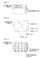
- FIG. 2 is an explanatory view showing Example 1 of obtained luminance-hue judgment data by a luminance-hue judgment sensor in the see-through side-view monitor system Al according to Embodiment 1.
- FIG. 3 is an explanatory view showing Example 2 of obtained luminance-hue judgment data by a luminance-hue judgment sensor in the see-through side-view monitor system Al according to Embodiment 1.
- FIG. 4 is an explanatory view showing Example 3 of obtained luminance-hue judgment data by a luminance-hue judgment sensor in the see-through side-view monitor system Al according to Embodiment 1.
- FIG. 5 is a flowchart showing a flow of an external image luminance follow-up display control processing performed in a control circuit 45 in the see-through side-view monitor system A 1 according to Embodiment 1.
- FIG. 6 is a flowchart showing a flow of a luminance abrupt change handling display control processing performed in the control circuit 45 in the see-through side-view monitor system A 1 according to Embodiment 1.
- FIG. 7 is a flowchart showing a flow of a hue conversion display control processing performed in the control circuit 45 in the see-through side-view monitor system A 1 according to Embodiment 1.
- FIG. 8 is a view showing a hue circle used in the hue conversion display control processing according to Embodiment 1.
- FIG. 9 is a flowchart showing a flow of an alarm display control processing performed in the control circuit 45 in the see-through side-view monitor system Al according to Embodiment 1.
- FIG. 10 is a view showing a vehicle interior still image previously photographed toward a side of a left front part from a position of a driver's viewpoint.
- FIG. 11 is a perspective view showing an image of a state where a vehicle shape is projected on a road surface from a vehicle where the see-through side-view monitor system Al according to Embodiment 1 is installed.
- FIG. 12 is a view showing an image (opaque part) in case where the image of the vehicle shape projected on the road surface from the vehicle where the see-through side-view monitor system A 1 according to Embodiment 1 is installed is transmitted and viewed from the position of the driver's viewpoint.
- FIG. 13 is a view showing an image where the “opaque part DE” of FIG. 12 is set on the vehicle interior image RP shown in FIG. 10 in the see-through side-view monitor system Al according to Embodiment 1.
- FIG. 14 is a view showing a semitransparent vehicle interior image RG where the “opaque part DE,” a “transparent part CE,” and a “semitransparent part GE” are set on the vehicle interior image RP shown in FIG. 10 in the see-through side-view monitor system A 1 according to Embodiment 1.
- FIG. 15 is an image view showing an inverted luminance screen when the semitransparent vehicle interior image RG is inverted and displayed in the see-through side-view monitor system A 1 according to Embodiment 1.
- FIG. 16 is an entire system block diagram showing a see-through back-view monitor system A 2 (an example of the vehicle peripheral image display system) according to Embodiment 2.
- FIG. 17 is a view showing a semitransparent vehicle interior image RG where the “opaque part DE,” a “transparent part CE,” and a “semitransparent part GE” are set on the vehicle interior image RP of a back side of the vehicle in the see-through back-view monitor system A 2 according to Embodiment 2.
- FIG. 18 is an entire system block diagram showing a see-through front-view monitor system A 3 (an example of the vehicle peripheral image display system) according to Embodiment 3.
- FIG. 19 is a flowchart showing a flow of a blending ratio sensor cooperative control processing performed in the control circuit 45 in the see-through front-view monitor system A 3 according to Embodiment 3.
- FIG. 20 is a view showing an image where the “opaque part DE” is set on left, right and center divided areas in a front camera image in the see-through front-view monitor system A 3 according to Embodiment 3.
- FIG. 21 is a view showing the semitransparent vehicle interior image RG where the “opaque part DE,” the “transparent part CE,” and the “semitransparent part GE” are set on the vehicle interior image RP in the see-through front-view monitor system A 3 according to Embodiment 3.
- an entire system configuration includes, as represented in FIG. 1 , a blind spot eliminating camera and a digital image processor, which process an image from the camera and a blending processor for a semitransparent image.
- a basic configuration is the same.
- a position and a number of cameras are flexible for a configuration addressing cost and the like.
- transmissivity initial value of transmissivity
- Embodiment 1 using a blind spot eliminating side camera installed in a side mirror or disposed at a vicinity of the side mirror as an on-vehicle blind spot camera, is an example of a see-through side-view monitor system where a side camera image of a side portion of a front part of a vehicle, which is in a blind spot from the driver, is displayed on a monitor as an image to be viewed through from a vehicle interior.
- FIG. 1 is an entire system block diagram showing the see-through side-view monitor system A 1 (an example of a vehicle peripheral image display system) according to Embodiment 1.
- the see-through side-view monitor system A 1 includes, as shown in FIG. 1 , a side camera 1 (on-vehicle blind spot camera), an image processing control unit 2 (monitor image generating means), a monitor 3 , a blending ratio manual control interface 4 (blending ratio manual operation means), an external sensor 5 , and a hue manual control interface 6 (vehicle interior image color manual operation means).
- the side camera 1 is built into a left side mirror or disposed at a vicinity of the left side mirror and images a side portion of a front part of the vehicle, which is in a blind spot from the driver.
- the side camera 1 obtains a real camera image data of the side portion of the front part of the vehicle by an image pickup device (a CCD, a CMOS, or the like).
- an image pickup device a CCD, a CMOS, or the like.
- the monitor 3 is set at a position in the vehicle interior to be visually confirmed by the driver (for example, at a position on an instrument panel, or the like) and receives and display a display image from the image processing control unit 2 .
- the monitor 3 has a display screen 3 a by a liquid crystal display, an organic EL display, or the like.
- a monitor in exclusive use for the see-through side-view monitor system A 1 may be set, a monitor in exclusive use for the blind spot eliminating camera system may be set, or a monitor which is also used for a navigation system, or the other system may be used.
- the image processing control unit 2 generates the display image to the monitor 3 based on input information from the blending ratio manual control interface 4 , the external sensor 5 , and the hue manual control interface 6 in addition to the real camera image input from the side camera 1 .
- the blending ratio manual control interface 4 has, for example, a touch panel switch of the monitor 3 and arbitrarily adjusts transmissivity of a “semitransparent part GE” set in the vehicle interior image by a manual operation.
- the external sensor 5 is a sensor, a switch, or the like which provides input information to the image processing control unit 2 , and includes, as shown in FIG. 1 , a rudder sensor 51 , a speed sensor 52 , an illumination ON/OFF switch 53 , a function switch 54 , and the other sensors or switches.
- a blending circuit section 46 a automatically adjusts the transmissivity of the “semitransparent part GE” set in the vehicle interior image so as to enhance the visibility of a composite image displayed on the monitor 3 based on surrounding environment information (daytime, evening, nighttime, weather, and the like) obtained by the external sensor 5 or vehicle information (rudder, vehicle speed, and the like).
- the hue manual control interface 6 has, for example, a touch panel switch of the monitor 3 and arbitrarily adjusts an entire hue of the vehicle interior image to be superimposed by a manual operation.
- the image processing control unit 2 includes, as shown in FIG. 1 , a decoder 41 , an image memory 42 , an image processor 43 , an image memory 44 (image storage section), a control circuit (CPU) 45 , a superimposing circuit 46 (image composite circuit), an encoder 47 , a blending external controller 48 , a luminance-hue judgment sensor 49 a (external image color judging section), a luminance-hue conversion block 49 b (vehicle interior image color automatically adjusting section), and a hue external controller 49 c (vehicle interior image color external controller).
- the decoder 41 performs an analog-digital conversion of the real camera image data input from the side camera 1 .
- the image memory 42 stores the real camera image data where the conversion into digital is performed, which is input from the decoder 41 .
- the image processer 43 performs a viewpoint conversion of the real camera image data input from the image memory 42 into a virtual camera image to be viewed from a position of a driver's viewpoint.
- a viewpoint conversion as if a virtual camera is disposed at a vicinity of the driver's viewpoint is performed and also “an image processings including various processings (luminance adjustment, color correction, edge correction, and the like)” are also performed.
- the image memory 44 is a memory for superimposing and stores a vehicle interior image RP ( FIG. 10 ) previously photographed from the driver's viewpoint as the vehicle interior image.
- the control circuit 45 is a central processing circuit (e.g., a CPU) managing all information processings and control outputs related to image processings according to input information.
- control programs performing various image processing controls such as an external image luminance follow up display control, a luminance abrupt change handling display control, a hue conversion display control, an alarm display control, and the like are set.
- the superimposing circuit 46 basically generates a semitransparent vehicle interior image RG ( FIG. 14 ) by generating a semitransparent image of the vehicle interior image RP from the image memory 44 , and by image composition superimposing the semitransparent vehicle interior image RG onto the virtual camera image from the image processor 43 , a composite image expressing the virtual camera image through the semitransparent vehicle interior image RG is generated.
- the superimposing circuit 46 has a blending circuit section 46 a dividing the vehicle interior image RP previously photographed from the driver's viewpoint into areas and setting different transmissivities in the respective areas.
- the blending circuit section 46 a sets, within the vehicle interior image RP ( FIG.
- a shade area SE which is obtained by projecting the vehicle onto the road surface as a “opaque part DE” with transmissivity of 0%
- an area corresponding to a window glass of the vehicle as a “transparent part CE” with transmissivity of 100%
- areas other than the shade area and the window glass area as a “semitransparent part GE” with arbitrary transmissivities ( FIG. 14 ).
- the encoder 47 receives the composite image signal where the semitransparent vehicle interior image RG is superimposed on the virtual camera image from the superimposing circuit 46 and outputs the composite image signal to the monitor 3 via the digital-analog conversion.
- the blending external controller 48 When receiving a transmissivity adjustment signal from the blending ratio manual control interface 4 , the blending external controller 48 outputs a transmissivity control command arbitrarily adjusting the transmissivity of the “semitransparent part GE” set in the vehicle interior image in a range from 0% to 100% to the control circuit 45 .
- the luminance-hue judgment sensor 49 a receives the real camera image data of the external image from the side camera 1 , judges average luminance and hue based on the real camera image data, and outputs the judgment result to the control circuit 45 .
- the luminance-hue judgment sensor 49 a loads data of each pixel forming the real camera image as a digital data luminance signal Y and a color difference signal CbCr (or RGB data).
- the luminance-hue judgment sensor 49 a accumulates (stores), as shown in FIG. 2 , data in each horizontal line in a horizontal scanning line direction and averages the plurality of accumulated data in all scanning lines to judge brightness (luminance) and hue of the entire image.
- This judging method is the easiest.
- particular blocks (judgment areas 1 to 5 ) may be set at four corners, a center, and the like in the loaded original data (screen) to judge brightness and hue of the entire image by an average in each block.
- FIG. 3 particular blocks (judgment areas 1 to 5 ) may be set at four corners, a center, and the like in the loaded original data (screen) to judge brightness and hue of the entire image by an average in each block.
- grid sample lines (representative vertical lines, representative horizontal lines) in vertical and horizontal directions every several pixels may be set in the loaded original data to judge brightness and hue of the entire image by accumulating (storing) data in each sample line and averaging a plurality of accumulated data.
- the luminance-hue conversion block 49 b receives the luminance-hue judgment result of the external image from the control circuit 45 and the semitransparent vehicle interior image data from the image memory 44 , automatically adjusts the luminance and hue of the semitransparent vehicle interior image so as to enhance the visibility with respect to the luminance and hue of the external image, and outputs the adjusted semitransparent vehicle interior image to the superimposing circuit 46 . Furthermore, the luminance-hue conversion block 49 b receives a hue control command from the hue external controller 49 c and the semitransparent vehicle interior image from the image memory 44 , adjusts the hue of the semitransparent vehicle interior image and outputs the adjusted semitransparent vehicle interior image to the superimposing circuit 46 .
- the hue external controller 49 c When receiving the hue adjustment signal from the hue manual control interface 6 , the hue external controller 49 c outputs a hue control command arbitrarily adjusting the entire hue of the vehicle interior image to be superimposed depending on preference to the luminance-hue conversion block 49 b.
- FIG. 5 is a flowchart showing a flow of an external image luminance follow-up display control processing (external image luminance follow-up display control mode) performed in the control circuit 45 in the see-through side-view monitor system A 1 according to Embodiment 1.
- an external image luminance follow-up display control processing external image luminance follow-up display control mode
- step S 51 it is judged whether or not the function switch 54 is ON. In the case of Yes (i.e., the switch 54 is ON), the process moves to step S 52 . In the case of No (i.e. the switch 54 is OFF), the process returns to the judgment in step S 51 .
- step S 52 following the judgment that the function switch 54 is ON in step S 51 , luminance judgment data and hue judgment data are obtained as judgment data by the luminance-hue judgment sensor 49 a and the process moves to step S 53 .
- step S 53 following obtaining the luminance-hue judgment data in step S 52 , it is judged whether or not the judged luminance detection value is less than a first set value Y1 indicating a darkness threshold value.
- a first set value Y1 indicating a darkness threshold value.
- the process moves to step S 55 .
- the process moves to step S 54 .
- luminance means a measured light amount obtained by evaluating intensity of light emitting toward an observer from a light source or a secondary light source (a reflection surface or transmitting surface) with sensitivity of a human eye (CIE standard spectral luminous efficiency V[ ⁇ ]), which is specified in a particular direction (observing direction).
- luminance in a normal state means luminance with which the semitransparent vehicle interior image to be superimposed on the virtual camera image is clearly distinguished when brightness outside of the vehicle is brightness of the daytime.
- step S 55 following a judgment that the luminance detection value ⁇ Y1 in step S 53 , it is judged whether or not the judged luminance detection value is less than a second set value Y2 (i.e., Y1 ⁇ Y2) indicating a nighttime threshold value.
- a second set value Y2 i.e., Y1 ⁇ Y2 indicating a nighttime threshold value.
- Yes i.e., the luminance detection value ⁇ Y2
- the process moves to step S 57 .
- “brightness” is one of three attributes of color and means lightness of color. The three attributes of color are “hue (color shade)” and “saturation” in addition to “brightness.”
- step S 57 following a judgment that the luminance detection value ⁇ Y2 in step S 55 , the luminance of the vehicle interior image to be superimposed is inverted to display black lines as white lines and the process returns to step S 51 .
- FIG. 6 is a flowchart showing a flow of a luminance abrupt change handling display control processing (luminance abrupt change handling display control mode) performed by the control circuit 45 in the see-through side-view monitor system A 1 according to Embodiment 1.
- luminance abrupt change handling display control mode luminance abrupt change handling display control mode
- step S 61 it is judged whether or not the function switch 54 is ON. In the case of Yes (i.e., the switch 54 is ON), the process moves to step S 62 . In the case of No (i.e., the switch 54 is OFF), the process returns to the judgment in step S 61 .
- step S 62 following a judgment that the function switch 54 is ON in step S 61 , luminance judgment result and hue judgment result are obtained as judgment data by the luminance-hue judgment sensor 49 a and the process moves to step S 63 .
- step S 65 following the judgment that the luminance detection value >Y3 in step S 63 , the luminance of the vehicle interior image to be superimposed is shifted down or the brightness is decreased, and the process returns to step S 61 .
- FIG. 7 is a flowchart showing a flow of a hue conversion display control processing (hue conversion display control mode) performed in the control circuit 45 in the see-through side-view monitor system A 1 according to Embodiment 1.
- FIG. 8 is a view showing a hue circle used in the hue conversion display control processing in Embodiment 1.
- each step in FIG. 7 will be explained.
- step S 71 it is judged whether or not the function switch 54 is ON. In the case of Yes (i.e., the switch 54 is ON), the process moves to step S 72 . In the case of No (i.e., the switch 54 is OFF), the process returns to the judgment in step S 71 .
- step S 72 following a judgment that the function switch 54 is ON in step S 71 , luminance judgment result and hue judgment result are obtained as judgment data by the luminance-hue judgment sensor 49 a and the process moves to step S 73 .
- step S 73 following obtaining the luminance-hue judgment data in step S 72 , the judged hue detection value is compared with a hue set value X and it is judged whether or not a hue deviation due to a difference therebetween is less than a first threshold value Z1.
- Yes i.e., the hue deviation ⁇ Z1
- the process moves to step S 74 .
- the hue set value X is obtained by judging a hue of the vehicle interior image before performing hue conversion, which is set and stored in the image memory 44 .
- step S 75 following a judgment that the hue deviation ⁇ Z1 in step S 73 , the judged hue detection value is compared with the hue set value X and it is judged whether or not the hue deviation due to the difference therebetween is less than a second threshold value Z2 (i.e., Z2 ⁇ Z1).
- a second threshold value Z2 i.e., Z2 ⁇ Z1
- Yes i.e., the hue deviation ⁇ Z2
- the process moves to step S 77 .
- step S 77 following a judgment that the hue deviation ⁇ Z2 in step S 75 , the hue of the vehicle interior image to be superimposed is converted into a hue of a complementary color and the process returns to step S 71 .
- the colors at diagonal positions in the hue circle shown in FIG. 8 are in a complementary color relationship.
- the hue of the external image is red
- the hue is preferably converted into “cyan” the most.
- a complementary color area at a diagonal position with respect to “red” has “blue” and “green” other than “cyan” and therefore red may be converted into “blue” or “green.”
- FIG. 9 is a flowchart showing a flow of an alarm display control processing (alarm display control mode) performed in the control circuit 45 in the see-through side-view monitor system A 1 according to Embodiment 1. Hereinafter, each step in FIG. 9 will be explained.
- step S 91 it is judged whether or not the function switch 54 is ON. In the case of Yes (i.e., the switch 54 is ON), the process moves to step S 92 . In the case of No (i.e., the switch 54 is OFF), the process returns to the judgment in step S 91 .
- step S 92 following a judgment that the function switch 54 is ON in step S 91 , speed data is obtained by the speed sensor 52 and obstacle existence-non existence data is obtained from the image processor 43 , and then the process moves to step S 93 .
- the “obstacle existence-non existence data” is obtained by analyzing the real camera image data input to the image processor 43 and judging whether or not an image indicating an obstacle exists in the analyzed image.
- the set value V is set as a judging threshold of a low speed driving and a normal driving and set to a low speed value.
- step S 95 following a judgment that the speed detection value ⁇ V in step S 93 , it is judged whether or not an obstacle is not recognized by the obtained obstacle existence-non existence data. In the case of Yes (i.e., the obstacle is not recognized), the process moves to step S 97 . In the case of No (i.e., the obstacle is recognized), the process moves to step S 96 .
- step S 96 following a judgment that the obstacle is recognized in step S 95 , the hue of the entire screen of the vehicle interior image to be superimposed is changed according to an approaching degree to the obstacle (for example, from orange gradually to red) and the process returns to step S 91 .
- step S 97 following a judgment that the obstacle is not recognized in step S 95 , the luminance and hue of the vehicle interior image to be superimposed is kept and the process returns to step S 91 .
- An object of the present invention including Embodiment 1 to Embodiment 3 is to propose a vehicle peripheral image display system with low cost, which has an external camera capable of contributing to blind spot elimination and is capable of displaying a camera image by using an image processing and with which the driver can intuitively recognize the image to be viewed through the vehicle only by viewing the image and understand vehicle behavior in the image.
- the display system proposed by the inventors of the present application is mainly as follows:
- a display system capable of automatically changing a basic transmissivity depending on a driving situation. For example, transmissivity is changed depending on the luminance of the external image when it is getting dark to make it easy to see the external image.
- a display system Constructing a display system performing an automatic control of a luminance and a hue of the vehicle interior image to be superimposed to enhance visibility according to a luminance and a hue of the external image.
- the system is capable of changing the luminance and hue by a manual operation according to preference of visibility, which varies largely among different individuals.
- the luminance of the semitransparent vehicle interior image is increased when it is getting dark
- the luminance of the semitransparent vehicle interior image is inverted at nighttime
- the luminance of the semitransparent vehicle interior image is decreased when light of an oncoming vehicle enters the camera
- the hue of the semitransparent vehicle interior image is converted to have a hue deviation when hues of the external image and the semitransparent vehicle image are close to each other, and the like.
- FIG. 10 is a view showing a vehicle interior still image previously photographed toward a side portion of a front part from a position of the driver's viewpoint.
- FIG. 11 is a perspective view showing an image of a state where a vehicle shape is projected onto a road surface from the vehicle on which the see-through side-view monitor system A 1 according to Embodiment 1 is installed.
- FIG. 12 is a view showing an image (opaque part) which is obtained by projecting the vehicle shape on the road surface from the vehicle on which the see-through side-view monitor system A 1 according to Embodiment 1 and is viewed through from a position of the driver's viewpoint.
- FIG. 13 is a view showing an image where the “opaque part DE” of FIG.
- FIG. 14 is a view showing a semitransparent vehicle interior image RG where the “opaque part DE,” a “transparent part CE,” and a “semitransparent part GE” are set on the vehicle interior image RP shown in FIG. 10 in the see-through side-view monitor system A 1 according to Embodiment 1.
- a monitor image display operation with a transmitting image will be explained.
- An analog-digital conversion on a real camera image input from the side camera 1 is performed by the decoder 41 and stored in the image memory 42 . Then, in the image processor 43 , “image processings including various processings (luminance adjustment, color correction, edge correction, and the like)” and a “viewpoint conversion processing as if the virtual camera is disposed at the vicinity of the driver's viewpoint” are performed to obtain the virtual camera image.
- the image memory 44 stores the vehicle interior image RP ( FIG. 10 ) which is previously photographed as the vehicle interior image.
- the superimposing circuit 46 generates a semitransparent image of the vehicle interior image RP from the image memory 44 to generate a semitransparent vehicle interior image RG ( FIG. 14 ) and performs an image composition superimposing the semitransparent vehicle interior image RG on the virtual camera image from the image processor 43 to generate a composite image expressing the virtual camera image through the semitransparent vehicle interior image RG.
- the composite image obtained by superimposing in the superimposing circuit 46 is sent to the encoder 47 and processed via the digital/analog conversion in the encoder 47 and output to the monitor 3 to be displayed on the display screen 3 a.
- the projected surface is vertically projected on the road surface and the projected image is positioned at the same height position as that of a tire contact surface.
- the image shown in FIG. 12 indicates a vehicle body shape itself while actually driving. Therefore if it is superimposed on the image from the driver's viewpoint, contacting the projected image means contacting the vehicle body.
- the image obtained by performing viewpoint conversion is displayed by being superimposed on the projected surface, only by viewing the image (side-view screen), senses for the vehicle required when preventing wheels from falling into a side ditch or avoiding obstacles can be understood at one view and intuitively understood so that the system can have a larger contribution to a safe driving. That is, as shown in FIG. 13 , a part where the vehicle body shape is projected is set as an “opaque part DE” with transmissivity of 0% and the vehicle interior image RP is directly displayed.
- the vehicle interior image RP is displayed at arbitrary transmissivities. More specifically, as shown in FIG. 14 , a window glass part is set as a “transparent part CE” with transmissivity of 100%, the other part is set as a “semitransparent part GE” and further an “opaque part DE” with transmissivity of 0% is added. Thereby, the vehicle interior image RP from the driver's viewpoint can be displayed as the semitransparent vehicle interior image RG at 100%.
- the actually-implemented semitransparent vehicle interior image RG is confirmed, a floor part where the vehicle interior image RP is directly used is clearly distinguished from a door part where transmissivity is 10 to 50% so that the vehicle shape can be easily distinguished.
- the real camera image of the side camera installed in the side mirror is converted into the virtual camera image as if it is photographed by the virtual camera from the position of the driver's viewpoint and the semitransparent vehicle interior image is superimposed on the virtual camera image and displayed so that the transmitting image having more sense of reality can be expressed. Furthermore, by displaying shades, which are obtained by vertically projecting the actual size and shape of the vehicle on the road surface, positional relationship between the actual vehicle and the external transmitting image can be displayed and clearly understood.
- an area of the shades which are projected according to the size and shape of the vehicle body on a road surface which is a virtual space screen in case where the above viewpoint conversion is performed, is displayed as the “opaque part DE” with transmissivity of 0%, and the other area is displayed as the semitransparent parts (“transparent part GE,” “semitransparent part GE”) with arbitrary transmissivities.
- transparent part GE semitransparent part
- the superimposed screen where the size and shape of the vehicle body are clear is displayed on the monitor screen 3 a and the other part is a blend screen with the camera image.
- the driver's viewpoint camera is provided at a vicinity of the driver's viewpoint but not at a position of the driver's viewpoint. Therefore, there is disparity in the camera image which is obtained by the driver's viewpoint camera with respect to the image which is actually viewed from the driver's viewpoint.
- an area SE where the shape of the vehicle is projected on the road surface is set as the “opaque part DE” with transmissivity of 0% of the vehicle interior image
- an area corresponding to a window glass of the vehicle is set as the “transparent part CE” with transmissivity of 100%
- an area other than the shade area and the window glass area is set as the “semitransparent part GE” (see FIG. 14 ).
- the “semitransparent part GE” if previously determined uniform transmissivity is used, user cannot arbitrarily change the transmissivity so usability is degraded. Moreover, since the screen has uniform transmissivity even in case where surrounding environment changes, visibility may be degraded.
- transmissivity of the “semitransparent part GE” is adjustable by a manual operation or is automatically adjustable.
- a transmissivity control command is output to the control circuit 45 and the blending circuit 46 a arbitrarily adjusts the transmissivity of the “semitransparent part GE” set in the vehicle interior image within a range of 0% to 100%.
- the blending circuit 46 a automatically adjusts the transmissivity of the “semitransparent part GE” set in the vehicle interior image based on surrounding environment information (daytime, time when it is getting dark, nighttime, weather, and the like) and vehicle information (rudder angle, vehicle speed) obtained by the external sensor 5 so as to enhance visibility of the composite image displayed on the monitor 3 .
- the system is capable of freely setting and updating the transmissivity of the “semitransparent part GE” so that high usability is achieved. Furthermore, if the function switch 54 is kept ON, the system automatically adjusts the transmissivity of the “semitransparent part GE” without user's operation and it is possible to maintain high visibility of the composite image displayed on the monitor 3 .
- FIG. 15 is an image view showing an inverted luminance screen when the semitransparent vehicle interior image RG is inverted and displayed in the see-through side-view monitor system A 1 according to Embodiment 1.
- a display control operation in an external image luminance follow up display control mode with reference to FIG. 15 based on the flowchart shown in FIG. 5 .
- step S 54 the lamination of the semitransparent vehicle interior image RG to be superimposed is set as a luminance in a normal state where high visibility is provided when the external image is bright.
- step S 51 When the external image captured by the side camera 1 when it is getting dark or under a cloudy weather is dark and the luminance detection value is less than the first set value Y1 and the second set value Y2 or more, in the flowchart of FIG. 5 , a flow from step S 51 to step S 52 , step S 53 , step S 55 and step S 56 is repeated. That is, in step S 56 , the luminance or brightness of the semitransparent vehicle interior image RG to be superimposed is shifted up.
- the entire luminance of the display screen 3 a of the monitor 3 is decreased and the semitransparent vehicle interior image RG is blended into the dark virtual camera image so that visibility may be degraded.
- the two images to be superimposed to each other have difference in luminance (brightness) so that visibility is improved.
- step S 51 When the external image captured by the side camera 1 at nighttime or the like is dark and the luminance detection value is less than the second set value Y2, in flowchart of FIG. 5 , a flow from step S 51 to step S 52 , step S 53 , step S 55 and step S 57 is repeated. That is, in step S 57 , as shown in FIG. 15 , the luminance of the semitransparent vehicle interior image RG to be superimposed is inverted to display black lines with white lines.
- the entire luminance of the display screen 3 a of the monitor 3 is largely decreased and the semitransparent vehicle interior image RG is completely blended into the dark virtual camera image so that visibility is remarkably degraded. Furthermore, even though the luminance of the semitransparent vehicle interior image RG to be superimposed is shifted up, the semitransparent vehicle interior image is blended into and not distinguished from the dark virtual camera image.
- the display screen of the monitor 3 by superimposing displays a line picture in a white image so that sense for vehicle can be intuitively understood even in the dark external camera image.
- the luminance can be shifted up by increasing the transmissivity and can be shifted down by decreasing the transmissivity by the blending ratio manual control interface 4 .
- step S 64 the luminance of the semitransparent vehicle interior image RG to be superimposed is in the normal state or in a luminance changed state by the above external image luminance follow up display control.
- step S 65 the luminance or the brightness of the semitransparent vehicle interior image RG to be superimposed is shifted down.
- a dazzlement prevention effect can be achieved at a certain degree by a luminance adjustment including an auto iris provided in the on-vehicle camera and the image to be superimposed can be distinguished.
- a luminance adjustment including an auto iris provided in the on-vehicle camera and the image to be superimposed can be distinguished.
- it cannot be sufficiently achieved by the luminance adjustment function of the on-vehicle camera.
- Embodiment 1 when there is an abrupt luminance change, for example, due to light of an oncoming vehicle entering the side camera 1 , or the like and thereby the luminance detection value is more than the third set value Y3, the luminance or the brightness of the semitransparent vehicle interior image RG to be superimposed is shifted down.
- the external image virtual camera image
- the semitransparent vehicle interior image RG which is blackish at a whole is superimposed, the semitransparent vehicle interior image RG can be clearly distinguished from the external image and visibility when there is an abrupt luminance change can be effectively improved.
- step S 71 When the hue of the external image is different from that of the semitransparent vehicle interior image RG and the hue deviation obtained when the hue detection value is compared with the set value X is the first threshold value Z1 or more, in the flowchart of FIG. 7 , a flow from step S 71 to step S 72 , step S 73 and step S 74 is repeated. That is, in step S 74 , the hue of the semitransparent vehicle interior image RG to be superimposed is kept without change.
- step S 71 When the hue of the external image becomes close to that of the semitransparent vehicle interior image RG and the hue deviation obtained when the hue detection value is compared with the set value X is less than the first threshold value Z1 and the second threshold value Z2 or more, in the flowchart of FIG. 7 , a flow from step S 71 to step S 72 , step S 73 , step S 75 and step S 76 is repeated. That is, in step S 76 , the luminance or the brightness of the semitransparent vehicle interior image RG to be superimposed is increased.
- step S 71 the hue of the external image is close to that of the semitransparent vehicle interior image RG and the hue deviation obtained when the hue detection value is compared with the set value X is less than the second threshold value Z2
- step S 73 the hue of the semitransparent vehicle interior image RG to be superimposed is converted into the complementary hue which is positioned in a diagonal position in the hue circle shown in FIG. 8 to be displayed.
- the hues have the same blown color
- the brightness of the color is different
- light brown can be distinguished from dark brown.
- the hues have a small difference
- the distinguishability can be improved by differentiating the brightness of color. Therefore, in case where the hue of the external image and the hue of the semitransparent vehicle interior image RG have hue levels similar to but different from each other, the visibility can be improved by increasing the luminance (brightness) of the semitransparent vehicle interior image RG to be superimposed.
- the main color is greenish color. If the semitransparent vehicle interior image RG to be superimposed has mainly the similar greenish color, the visibility becomes degraded. In this case, if the semitransparent vehicle interior image RG has “a color in magenta which exists at an opposite side in the hue circle,” it can be distinguished. Furthermore, if it is outside during sunset, the main color is reddish color. If the semitransparent vehicle interior image RG to be superimposed has mainly the similar reddish color, the visibility becomes degraded. In this case, if the semitransparent vehicle interior image RG has “a color in cyan which exists at an opposite side in the hue circle,” it can be distinguished.
- step S 94 the hue of the entire screen of the semitransparent vehicle interior image RG is converted into a reddish hue.
- step S 96 the hue of the entire screen of the semitransparent vehicle interior image RG to be superimposed is converted so as to gradually strengthen red color according to closeness to the obstacle.
- step S 91 if there is no vehicle speed condition and obstacle condition, in the flowchart of FIG. 9 , a flow from step S 91 , step S 92 , step S 93 , step S 95 and step S 97 is repeated. That is, in step S 97 , the luminance and the hue of the semitransparent vehicle interior image RG to be superimposed is maintained.
- the side-view monitor system is used for confirming safe conditions when moving in a width direction and starting an engine, and the like, and therefore is frequently used when the vehicle stops or runs at a very low speed. Therefore, in case where the system it to be used when the vehicle runs faster than at a certain speed, the monitor 3 is continuously viewed and therefore sense for speed or sense for understanding a space is emphasized more than in an actual situation, so that uncomfortable feeling is often caused. This make the safety degraded in its original intention and therefore, such a situation is preferably judged to indicate an alarm for decreasing speed for a safe driving. Moreover, in case where recognition of an obstacle is performed by image analysis in the image processing control unit 2 , it is preferable to indicate an alarm for notifying an existence of an obstacle to enhance driving for getting around the obstacle when the obstacle is recognized.
- an alarm operation is performed in conjunction with the speed sensor 52 or the like. That is, an excessive speed condition is judged to change the entire hue of the semitransparent vehicle interior image RG to be superimposed into reddish color so that an alarm to decrease the vehicle speed is provided to the driver to ensure the safety. Furthermore, if an obstacle is recognized, an alarm display using a hue change according to the closeness to the obstacle is performed to promote handling collision, inclusion, wheels falling down, and the like at an early stage to ensure the safety.
- a vehicle peripheral image display system including an on-vehicle blind spot camera (side camera 1 ) provided on a vehicle and imaging a peripheral of the vehicle, a monitor 3 set at a position in a vehicle interior for a driver to visually confirm the monitor, and a monitor image generating means (image processing control unit 2 ) generating a display image to be displayed on the monitor 3 based on a real camera image input from the on-vehicle blind spot camera(side camera 1 )
- the monitor image generating means includes an image processor 43 performing a viewpoint conversion of the real camera image input from the on-vehicle blind spot camera (side camera 1 ) into a virtual camera image to be viewed from a position of a driver's viewpoint, an external image color judging section (luminance-hue judgment sensor 49 a ) judging a color of an external image from the on-vehicle blind spot camera (side camera 1 ) based on at least one of
- the virtual camera image is clearly distinguished from the semitransparent vehicle interior image RG and the external situation which is in a blind spot from the driver can be transmitted and clearly visually confirmed with a positional relationship with the vehicle.
- the monitor image generating means (image processing control unit 2 ) has an image storage section (image memory 44 ) storing a vehicle interior still image which is previously photographed from the driver's viewpoint as the vehicle interior image, and the vehicle interior image color automatically adjusting section (luminance-hue conversion block 49 b ) generates a semitransparent image of the vehicle interior image from the image storage section (image memory 44 ) to obtain the semitransparent vehicle interior image RG.
- image processing control unit 2 has an image storage section (image memory 44 ) storing a vehicle interior still image which is previously photographed from the driver's viewpoint as the vehicle interior image, and the vehicle interior image color automatically adjusting section (luminance-hue conversion block 49 b ) generates a semitransparent image of the vehicle interior image from the image storage section (image memory 44 ) to obtain the semitransparent vehicle interior image RG.
- a low cost system which only uses an on-vehicle blind spot camera (side camera 1 ) is provided while the semitransparent vehicle interior image RG to be viewed from the driver's viewpoint can be obtained without causing disparity with respect to an actual driver's viewpoint, which is caused by the driver's viewpoint camera.
- the external image color judging section is a luminance-hue judgment sensor 49 a judging average luminance and hue of the external image from the on-vehicle blind spot camera (side camera 1 ) and the vehicle interior image color automatically adjusting section is a luminance-hue conversion block 49 b which automatically adjusts the luminance and hue of the semitransparent vehicle interior image RG based on a color judgment result of the external image by the luminance-hue judgment sensor 49 a so as to enhance visibility with respect to the luminance and hue of the external image.
- the luminance and the hue of the semitransparent vehicle interior image RG can be automatically adjusted so as to enhance the visibility according to the average luminance and hue of the external image from the on-vehicle blind spot camera (side camera 1 ).
- the monitor image generating means (image processing control unit 2 ) has an external image luminance follow-up display control mode (see FIG. 5 ) in which a luminance detection value from the luminance-hue judgment sensor 49 a is loaded, a display where the luminance of the semitransparent vehicle interior image RG is differentiated from that of the external image is displayed when the luminance detection value is a first set value Y1 indicating a dark threshold value or more, a display where the luminance of the semitransparent vehicle interior image RG is increased to be differentiated from the luminance of the external image is displayed when the luminance detection value is less than the first set value Y1 and a second set value Y2 indicating a night threshold value or more, and a display where the luminance of the semitransparent vehicle interior image RG is inverted and black lines are displayed by white lines is displayed when the luminance detection value is less than the second set value Y2.
- the external image displayed on the monitor 3 is clearly distinguished from the semitransparent vehicle interior image RG so that the visibility can be improved.
- the monitor image generating means (image processing control unit 2 ) has a luminance abrupt change handling display control mode (see FIG. 6 ) in which a luminance detection value from the luminance-hue judgment sensor 49 a is loaded, a display where the luminance of the semitransparent vehicle interior image RG is decreased to be entirely blackish is displayed when the luminance detection value is more than a third set value Y3 indicating an upper limit threshold value.
- the external image displayed on the monitor 3 is clearly distinguished from the semitransparent vehicle interior image RG so that visibility can be improved.
- the monitor image generating means (image processing control unit 2 ) has a hue conversion display control mode (see FIG. 7 ) in which a hue detection value from the luminance-hue judgment sensor 49 a is loaded, a display where the hue of the semitransparent vehicle interior image RG is kept is displayed when a hue deviation between the hue detection value and a set value X is a first threshold value Z1 or more, a display where the hue of the semitransparent vehicle interior image RG is kept and color is brighter is displayed when the hue deviation between the hue detection value and the set value X is less than the first threshold value Z1 and a second threshold value Z2 or more, vehicle interior image RG is converted into a hue of a complementary color which is in a complementary color area in a hue circle with respect to the hue of the external image to be displayed when the hue deviation between the hue detection value and the set value X is less than the second threshold value Z2.
- the external image displayed on the monitor 3 is clearly distinguished from the semitransparent vehicle interior image RG so that visibility can be improved.
- a vehicle speed detecting means (speed sensor 52 ) detecting a vehicle speed is provided, and the monitor image generating means (image processing control unit 2 ) has an alarm display control mode ( FIG. 9 ) in which a vehicle speed detection value from the vehicle speed detecting means (speed sensor 52 ) is loaded, and a hue of the entire semitransparent vehicle interior image RG is converted into a hue to make the driver recognize an alarm and is displayed when the vehicle detection value is a set value V or more.
- the monitor image generating means (image processing control unit 2 ) has a vehicle interior image color external controller (hue external controller 49 c ) arbitrarily adjusting at least one of the luminance, hue, saturation and brightness of the semitransparent vehicle interior image RG in accordance with an operation to a vehicle interior image color manual operation means (hue manual control interface 6 ) from outside.
- a vehicle interior image color external controller (hue external controller 49 c ) arbitrarily adjusting at least one of the luminance, hue, saturation and brightness of the semitransparent vehicle interior image RG in accordance with an operation to a vehicle interior image color manual operation means (hue manual control interface 6 ) from outside.
- At least one of the luminance, hue, saturation and brightness of the semitransparent vehicle interior image RG can be adjusted by a manual operation so that the system having high usability is provided.
- the image composite circuit (superimposing circuit 46 ) has a blending circuit section 46 a setting, within the vehicle interior image to be viewed from the driver's viewpoint, an area SE where the vehicle is projected on a road surface as an opaque part DE with transmissivity of the vehicle interior image RP which is 0%, an area corresponding to a window glass of the vehicle as a transparent part CE with transmissivity of the vehicle interior image RP which is 100%, an area other than the opaque part DE and the transparent part CE as a semitransparent part GE with an arbitrary transmissivity.
- a superimposed screen where a vehicle size and shape are clear is displayed on the monitor 3 and for example, it is possible to improve various misunderstanding and erroneous recognition occurring when a uniform semitransparent vehicle interior image is used.
- the vehicle behavior can be recognized at one view so that a judgment to avoid wheel falling into a side ditch can be easily performed.
- the on-vehicle blind spot camera is a side camera 1 used in a see-through side-view monitor system A 1 displaying a side portion of a front part from the vehicle which is in a blind spot from the driver as an image to be viewed through from the vehicle interior on the monitor 3 in the vehicle interior.
- Embodiment 2 using a blind spot eliminating back camera disposed at a back position of a vehicle as an on-vehicle blind spot camera, is an example of a see-through back-view monitor system where a back portion of the vehicle which is in a blind spot from the driver, is displayed on a monitor as an image to be viewed through from a vehicle interior.
- FIG. 16 is an entire system block diagram showing the see-through back-view monitor system A 2 (an example of a vehicle peripheral image display system) according to Embodiment 2.
- the see-through back-view monitor system A 2 includes, as shown in FIG. 16 , a back camera 21 (on-vehicle blind spot camera), an image processing control unit 2 (monitor image generating means), a monitor 3 , a blending ratio manual control interface 4 (blending ratio manual operation means), an external sensor 5 , and a hue manual control interface 6 (vehicle interior image color manual operation means).
- the side camera 21 is disposed at a vicinity of an inner side of a trunk lid of a license plate in case of a passenger car or at a vicinity of an upper end of a rear window in case of a large car such as a recreational vehicle and images a rear part of the vehicle, which is in a blind spot from the driver.
- the back camera 21 obtains a real camera image data of the back part of the vehicle by an image pickup device (a CCD, a CMOS, or the like).
- the image processing control unit 2 includes, as shown in FIG. 16 , a decoder 41 , an image memory 42 , an image processor 43 , an image memory 44 (image storage section), a control circuit (CPU) 45 , a superimposing circuit 46 (image composite circuit), an encoder 47 , a blending external controller 48 , a luminance-hue judgment sensor 49 a (external image color judging section), a luminance-hue conversion block 49 b (vehicle interior image color automatic adjusting section), and a hue external controller 49 c (vehicle interior image color external controller). Moreover, since each configuration is the same as that in Embodiment 1, the same numerical reference is used and the detailed explanation is omitted.
- FIG. 17 is a view showing a semitransparent vehicle interior image RG where the “opaque part DE,” a “transparent part CE,” and a “semitransparent part GE” are set on the vehicle interior image RP of a back side of the vehicle in the see-through back-view monitor system A 2 according to Embodiment 2.
- the see-through back-view monitor system A 2 has a configuration where the side camera 1 of the see-through side-view monitor system A 1 according to Embodiment 1 is replaced by the back camera 21 .
- a digital conversion on the real camera image from the back camera 21 is performed and a viewpoint conversion into the virtual camera image to be viewed from a driver's viewpoint is performed.
- a projected vehicle body image of FIG. 11 is formed with respect to the backward direction of the vehicle.
- the projected image area of the vehicle body is adapted to the virtual camera image of the back camera 21 and the vehicle interior image to be superimposed.
- a shaded area corresponding to a shade SE of the vehicle body by a vertical projection is set as the “opaque part DE” with transmissivity of 0% and also a window glass part is set as the “transparent part CE” with transmissivity of 100%. Further, other areas are set as the “semitransparent parts GE” which are obtained by performing an a blend with arbitrary transmissivities capable of being determined by a user and which are semitransparent.
- the camera is installed so as to image a vicinity of a bumper and sense for a vehicle is to be obtained with help from the imaged bumper or display of trajectory lines.
- Embodiment 2 similarly to the see-through side-view monitor system described in Embodiment 1, sense for vehicle is to be obtained by superimposing the vehicle interior image previously photographed in a backward direction from a driver's viewpoint. Accordingly, it is possible to vividly express the image expressed by the see-through back-view monitor system A 2 as an image as if it is viewed through a backward of the vehicle body. Furthermore, other operations are the same as those in Embodiment 1 and therefore detailed explanation is omitted.
- the on-vehicle blind spot camera is a back camera 21 used in the see-through back-view monitor system A 2 which displays a back part from the vehicle which is in a blind spot from the driver as an image to be viewed through from a vehicle interior on the monitor 3 .
- Embodiment 3 using a blind spot eliminating front camera disposed at a front position of a vehicle as an on-vehicle blind spot camera, is an example of a see-through front-view monitor system where a front portion of the vehicle which is in a blind spot from the driver, is displayed on a monitor as an image to be viewed through from a vehicle interior.
- FIG. 18 is an entire system block diagram showing the see-through front-view monitor system A 3 (an example of a vehicle peripheral image display system) according to Embodiment 3.
- the see-through front-view monitor system A 3 includes, as shown in FIG. 18 , a left front camera 31 L (on-vehicle blind spot camera), a right front camera 31 R (on-vehicle blind spot camera), a center front camera 31 C (on-vehicle blind spot camera), an image processing control unit 2 (monitor image generating means), a monitor 3 , a blending ratio manual control interface 4 (blending ratio manual operation means), an external sensor 5 , and a hue manual control interface 6 (vehicle interior image color manual operation means).
- the external sensor 5 includes, as shown in FIG. 18 , a turn signal switch 55 in addition to a rudder sensor 51 , a speed sensor 52 , an illumination ON/OFF switch 53 , and a function switch 54 .
- the image processing control unit 2 includes, as shown in FIG. 18 , a left decoder 41 L, a right decoder 41 R, a center decoder 41 C, a left image memory 42 L, a right image memory 42 R, a center image memory 42 C, an image processor 43 , an image memory 44 (image storage section), a control circuit (CPU) 45 , a superimposing circuit 46 (image composite circuit), an encoder 47 , a blending external controller 48 , a luminance-hue judgment sensor 49 a (external image color judging section), a luminance-hue conversion block 49 b (vehicle interior image color automatic adjusting section), and a hue external controller 49 c (vehicle interior image color external controller). Moreover, each configuration is the same as that in FIG. 1 showing Embodiment 1.
- FIG. 19 is a flowchart showing a flow of a blending ratio sensor cooperative control processing performed in the control circuit 45 in the see-through front-view monitor system A 3 according to Embodiment 3.
- a user changes left and right blending ratio with arbitrary setting and a current transmissivity Tr1 is, for example, set to 30%.
- step S 191 it is judged whether or not the function switch 54 is ON. In the case of Yes (i.e., the switch 54 is ON), the process moves to step S 192 . In the case of No (i.e., the switch 54 is OFF), the judgment in step S 191 is repeated.
- step S 192 following to a judgment that the function switch is ON in step S 191 , it is judged whether or not an ON signal is being output from the turn signal switch. In the case of Yes (i.e., in a turn signal blinking on state), the process moves to step S 193 . In the case of No (i.e., in a turn signal off state), the process returns to step S 191 .
- step S 193 following a judgment that the On signal is being output from the turn signal switch 55 in step S 192 , it is judged whether or not the signal from the turn signal switch 55 is a right turning signal. In the case of Yes (i.e., the turn signal is right), the process moves to S 194 . In the case of No (i.e., the turn signal is left), the process moves to step S 196 .
- the set value Tr0 is a transmissivity threshold value to ensure a rightward field of view, which is in a turning direction.
- step S 195 following a judgment that Tr1 ⁇ Tr0 in step S 194 , the transmissivity of the right front camera image area is forcibly changed from the current transmissivity Tr1 to a transmissivity T (for example, Tr0) and the process returns to step S 191 .
- the set value Tr0 is a transmissivity threshold value to ensure a leftward field of view which is in a turning direction.
- step S 197 following a judgment that Tr1 ⁇ Tr0 in step S 196 , a transmissivity of the left front camera image area is forcibly changed from the current transmissivity Tr1 to a transmissivity T (for example, Tr0) and the process returns to step S 191 .
- FIG. 20 is a view showing an image where the “opaque part DE” is set on left, right and center divided areas in a front camera image in the see-through front-view monitor system A 3 according to Embodiment 3.
- FIG. 21 is a view showing the semitransparent vehicle interior image RG where the “opaque part DE,” the “transparent part CE,” and the “semitransparent part GE” are set on the vehicle interior image RP in the see-through front-view monitor system A 3 according to Embodiment 3.
- Embodiment 3 digitization and viewpoint conversion on the image of each of the front cameras 31 L, 31 R, 31 C are performed and a superimposing screen which is a vehicle interior image where the vehicle shape is vertically projected is superimposed thereon to obtain a composite image.
- an area where the vehicle shape is vertically projected on a road surface is set as the “opaque part DE” with transmissivity 0%.
- a wide angle screen image of more than 180 degrees is displayed on an area in the vehicle interior image RP other than the “opaque part DE.”
- a screen is formed where a camera image from the center front camera 31 C, a camera image from the left front camera 31 L, and a camera image from the right front camera 31 R are composed at a center area, a left area, and a right area, respectively.
- the image using cameras is configured to ensure field of view and is often displayed as one screen from the left, right and center front cameras 31 L, 31 R, 31 C.
- each of the camera images is composed and the wide angle screen image of 180 degrees or more is displayed.
- the semitransparent vehicle interior image RG which is divided into “the opaque part DE,” “the transparent part CE,” and “the semitransparent part GE” is superimposed on the image shown in FIG. 20 and as a result, as shown in FIG. 21 , the image as if an outside of the front side of the vehicle is viewed through the vehicle interior is provided to the driver.
- Embodiment 3 since the image area is divided into three by the three front cameras 31 L, 31 R, 31 C, in conjunction with the turn signal switch 55 outputting a switch signal when changing the moving direction by turning the handle left or right after slowing down or stopping, the “semitransparent part GE” of the transmissivities of the three divided image areas are automatically adjusted.
- step S 191 In case where the right turn signal is detected and the current transmissivity Tr1 is less than the set value Tr0, in the flowchart of FIG. 19 , the process moves from step S 191 to step S 192 , step S 193 , step S 194 and step S 195 . Then, in step S 195 , since the field of view in the right area is more important than that in the center area, the system performs an a blend operation for automatically increasing transmissivity in order to ensure a field of view.
- step S 191 In case where the left turn signal is detected and the current transmissivity Tr1 is less than the set value Tr0, in the flowchart of FIG. 19 , the process moves from step S 191 to step S 192 , step S 193 , step S 196 and step S 197 . Then, in step S 197 , since the field of view in the left area is more important than that in the center area, the system performs an a blend operation for automatically increasing transmissivity in order to ensure a field of view.
- the on-vehicle blind spot camera is each of left, right and center front cameras 31 L, 31 R, 31 C used in the see-through front-view monitor system A 3 displaying a front part of the vehicle which is in a blind spot from the driver on the monitor 3 provided in the vehicle interior.
- sense for a space for example, sense for positions of and a distance between an obstacle in a forward position of the vehicle and the vehicle, which is required when starting straight moving or turning from a stopping or slowing down state, or sense for positions of and a distance between an approaching vehicle and the vehicle can be intuitively understood and larger contribution to safe driving can be achieved.
- Embodiments 1 to 3 an example where the luminance and hue of the semitransparent vehicle interior image RG to be superimposed on the virtual camera image is changed according to the judgment result of the luminance and hue of the external image has been shown.
- an example where saturation and brightness are added to the luminance and hue of the external image, and the semitransparent vehicle interior image RG to be superimposed on the virtual camera image is changed according to a judgment result of at least one of the luminance, hue, saturation and brightness may be included in the present invention.
- Embodiments 1 to 3 examples where, as the semitransparent vehicle interior image RG to be superimposed on the virtual camera image, a previously prepared vehicle interior image RP which is divided into three parts, that is “the opaque part DE,” “the transparent part CE,” and “the semitransparent part GE.”
- a previously prepared vehicle interior image RP which is divided into three parts, that is “the opaque part DE,” “the transparent part CE,” and “the semitransparent part GE.”
- the entire vehicle interior image RP is set as “the semitransparent part GE” may be included.
- an example where the entire vehicle interior image RP is set as “the semitransparent part GE” and “the opaque part DE” is bordered and displayed may be included.
- an example where “a shade part” by being filled is set instead of “the opaque part DE” may be included.
- the previously prepared vehicle interior image RP is divided into two parts, that is, “the opaque part DE” (or “the shade part”) and “the semitransparent part GE” may be included. Furthermore, an example where the previously prepared vehicle interior image RP has “the opaque part DE” (or “the shade part”) and “a transparent part where transmissivity is gradationally changed” which are continuously changed may be included.
- the example of the see-through side-view monitor system A 1 is shown in Embodiment 1
- the example of the see-through back-view monitor system A 2 is shown in Embodiment 2
- the example of the see-through front-view monitor system A 3 is shown in Embodiment 3.
- the vehicle peripheral image display system can be applied to a monitor system where a monitor is shared and one of a side-view, a back-view, and a front-view, and the like is selected or automatically switched according to a given condition.
Applications Claiming Priority (1)
| Application Number | Priority Date | Filing Date | Title |
|---|---|---|---|
| PCT/JP2009/070488 WO2011070640A1 (ja) | 2009-12-07 | 2009-12-07 | 車両周辺画像表示システム |
Publications (1)
| Publication Number | Publication Date |
|---|---|
| US20120249789A1 true US20120249789A1 (en) | 2012-10-04 |
Family
ID=44145212
Family Applications (1)
| Application Number | Title | Priority Date | Filing Date |
|---|---|---|---|
| US13/514,575 Abandoned US20120249789A1 (en) | 2009-12-07 | 2009-12-07 | Vehicle peripheral image display system |
Country Status (4)
| Country | Link |
|---|---|
| US (1) | US20120249789A1 (ja) |
| EP (1) | EP2512133B1 (ja) |
| CN (1) | CN102714710B (ja) |
| WO (1) | WO2011070640A1 (ja) |
Cited By (23)
| Publication number | Priority date | Publication date | Assignee | Title |
|---|---|---|---|---|
| US20140160275A1 (en) * | 2012-12-04 | 2014-06-12 | Aisin Seiki Kabushiki Kaisha | Vehicle control apparatus and vehicle control method |
| US20140292805A1 (en) * | 2013-03-29 | 2014-10-02 | Fujitsu Ten Limited | Image processing apparatus |
| US20150269444A1 (en) * | 2014-03-24 | 2015-09-24 | Survision | Automatic classification system for motor vehicles |
| US20150269446A1 (en) * | 2014-03-24 | 2015-09-24 | Toyota Jidosha Kabushiki Kaisha | Boundary detection apparatus and boundary detection method |
| US20150302259A1 (en) * | 2013-02-21 | 2015-10-22 | Honda Motor Co., Ltd. | Driving assistance device and image processing program |
| US20150310637A1 (en) * | 2012-12-06 | 2015-10-29 | Tencent Technology (Shenzhen) Company Limited | Interface adjustment method, apparatus, and terminal |
| US20160350974A1 (en) * | 2014-01-10 | 2016-12-01 | Aisin Seiki Kabushiki Kaisha | Image display control device and image display system |
| US20170282813A1 (en) * | 2014-09-05 | 2017-10-05 | Aisin Seiki Kabushiki Kaisha | Image display control device and image display system |
| US20180211118A1 (en) * | 2017-01-23 | 2018-07-26 | Magna Electronics Inc. | Vehicle vision system with object detection failsafe |
| US10155476B2 (en) | 2011-08-17 | 2018-12-18 | Lg Innotek Co., Ltd. | Camera apparatus of vehicle |
| US20190031102A1 (en) * | 2016-01-28 | 2019-01-31 | Hon Hai Precision Industry Co., Ltd. | Image display system for vehicle use and vehicle equipped with the image display system |
| WO2019052936A1 (de) * | 2017-09-12 | 2019-03-21 | Bayerische Motoren Werke Aktiengesellschaft | Dynamisch kolorierte anzeige eines fahrzeugs |
| JP2019073091A (ja) * | 2017-10-13 | 2019-05-16 | トヨタ自動車株式会社 | 車両用表示装置 |
| US20190337455A1 (en) * | 2016-04-14 | 2019-11-07 | Nissan Motor Co., Ltd. | Mobile Body Surroundings Display Method and Mobile Body Surroundings Display Apparatus |
| US10609398B2 (en) * | 2017-07-28 | 2020-03-31 | Black Sesame International Holding Limited | Ultra-low bitrate coding based on 3D map reconstruction and decimated sub-pictures |
| US10696228B2 (en) * | 2016-03-09 | 2020-06-30 | JVC Kenwood Corporation | On-vehicle display control device, on-vehicle display system, on-vehicle display control method, and program |
| US10994665B2 (en) * | 2017-10-10 | 2021-05-04 | Mazda Motor Corporation | Vehicle display system |
| US11021136B1 (en) * | 2011-08-29 | 2021-06-01 | The Boeing Company | Methods and systems for providing a remote virtual view |
| US20210179086A1 (en) * | 2019-12-13 | 2021-06-17 | Honda Motor Co., Ltd. | Parking assisting device, parking assisting method and storage medium storing program for the parking assisting device |
| US11044395B2 (en) * | 2018-01-08 | 2021-06-22 | Connaught Electronics Ltd. | Method for generating a representation of an environment by shifting a virtual camera towards an interior mirror of a motor vehicle; as well as camera device |
| US11297371B1 (en) * | 2016-09-22 | 2022-04-05 | Apple Inc. | Vehicle video system |
| US11678035B2 (en) | 2017-10-05 | 2023-06-13 | University Of Utah Research Foundation | Translucent imaging systems and related methods |
| US11785827B2 (en) | 2016-11-10 | 2023-10-10 | Semiconductor Energy Laboratory Co., Ltd. | Display device and driving method of display device |
Families Citing this family (14)
| Publication number | Priority date | Publication date | Assignee | Title |
|---|---|---|---|---|
| JP6077214B2 (ja) * | 2012-02-06 | 2017-02-08 | 富士通テン株式会社 | 画像処理装置、画像処理方法、プログラム、及び画像処理システム |
| US20140114534A1 (en) * | 2012-10-19 | 2014-04-24 | GM Global Technology Operations LLC | Dynamic rearview mirror display features |
| KR101393881B1 (ko) * | 2012-10-24 | 2014-05-12 | 현대자동차주식회사 | 차량의 주차구획 인식방법 |
| EP3105920B1 (en) * | 2014-02-11 | 2020-07-22 | Robert Bosch GmbH | Brightness and color matching video from multiple-camera system |
| JP6413477B2 (ja) * | 2014-08-21 | 2018-10-31 | アイシン精機株式会社 | 画像表示制御装置および画像表示システム |
| JP6393653B2 (ja) * | 2015-04-09 | 2018-09-19 | 株式会社東海理化電機製作所 | 車両用視認装置 |
| CN105216715A (zh) * | 2015-10-13 | 2016-01-06 | 湖南七迪视觉科技有限公司 | 一种汽车驾驶员视觉辅助增强系统 |
| CN105611308B (zh) * | 2015-12-18 | 2018-11-06 | 盯盯拍(深圳)技术股份有限公司 | 视频画面处理方法、装置以及系统 |
| JP6876236B2 (ja) * | 2016-09-30 | 2021-05-26 | 株式会社アイシン | 表示制御装置 |
| CN111886858B (zh) * | 2018-03-15 | 2022-06-21 | 株式会社小糸制作所 | 车辆用影像系统 |
| CN113767620B (zh) * | 2019-05-07 | 2023-09-22 | Agc株式会社 | 显示系统、显示方法及透明显示体 |
| JP7167853B2 (ja) * | 2019-05-23 | 2022-11-09 | 株式会社デンソー | 表示制御装置 |
| JP2022048455A (ja) * | 2020-09-15 | 2022-03-28 | マツダ株式会社 | 車両用表示装置 |
| KR20220036258A (ko) * | 2020-09-15 | 2022-03-22 | 현대자동차주식회사 | 차량의 감성조명 제어 장치 및 그 방법 |
Citations (12)
| Publication number | Priority date | Publication date | Assignee | Title |
|---|---|---|---|---|
| US5280344A (en) * | 1992-04-30 | 1994-01-18 | International Business Machines Corporation | Method and means for adding an extra dimension to sensor processed raster data using color encoding |
| US6037914A (en) * | 1997-08-25 | 2000-03-14 | Hewlett-Packard Company | Method and apparatus for augmented reality using a see-through head-mounted display |
| US6476731B1 (en) * | 1998-12-03 | 2002-11-05 | Aisin Aw Co., Ltd. | Driving support device |
| US20030021490A1 (en) * | 2000-07-19 | 2003-01-30 | Shusaku Okamoto | Monitoring system |
| JP2005335410A (ja) * | 2004-05-24 | 2005-12-08 | Olympus Corp | 画像表示装置 |
| US20060050983A1 (en) * | 2004-09-08 | 2006-03-09 | Everest Vit, Inc. | Method and apparatus for enhancing the contrast and clarity of an image captured by a remote viewing device |
| JP2008171314A (ja) * | 2007-01-15 | 2008-07-24 | San Giken:Kk | 速度警報機能付カーナビ装置 |
| US20080231921A1 (en) * | 2007-03-22 | 2008-09-25 | Murata Machinery, Ltd. | Image Processing Apparatus |
| US20090052774A1 (en) * | 2005-03-25 | 2009-02-26 | Hideki Yoshii | Image processing apparatus, image display apparatus, and image display method |
| US20090180689A1 (en) * | 2008-01-11 | 2009-07-16 | Olympus Corporation | Color reproduction device, color reproduction method, and computer-readable recording medium recorded with color reproduction program |
| US7612813B2 (en) * | 2006-02-03 | 2009-11-03 | Aptina Imaging Corporation | Auto exposure for digital imagers |
| US20090290068A1 (en) * | 2008-05-22 | 2009-11-26 | Sanyo Electric Co., Ltd. | Signal Processing Device And Projection Display Apparatus |
Family Cites Families (8)
| Publication number | Priority date | Publication date | Assignee | Title |
|---|---|---|---|---|
| JP2002337605A (ja) * | 2001-05-18 | 2002-11-27 | Auto Network Gijutsu Kenkyusho:Kk | 車両用周辺視認装置 |
| JP4593070B2 (ja) * | 2001-12-12 | 2010-12-08 | 株式会社エクォス・リサーチ | 車両の画像処理装置 |
| US7212653B2 (en) * | 2001-12-12 | 2007-05-01 | Kabushikikaisha Equos Research | Image processing system for vehicle |
| CN1485227A (zh) * | 2002-09-24 | 2004-03-31 | 李大民 | 一种后视的方法及其实现该方法的装置 |
| JP4552525B2 (ja) | 2004-06-11 | 2010-09-29 | 株式会社エクォス・リサーチ | 車両の画像処理装置 |
| JP2008039395A (ja) | 2006-08-01 | 2008-02-21 | Dainippon Printing Co Ltd | 粘度測定装置および粘度測定方法 |
| JP5421788B2 (ja) * | 2008-02-20 | 2014-02-19 | クラリオン株式会社 | 車両周辺画像表示システム |
| JP2009225322A (ja) * | 2008-03-18 | 2009-10-01 | Hyundai Motor Co Ltd | 車両用情報表示システム |
-
2009
- 2009-12-07 EP EP09852037.2A patent/EP2512133B1/en active Active
- 2009-12-07 WO PCT/JP2009/070488 patent/WO2011070640A1/ja active Application Filing
- 2009-12-07 US US13/514,575 patent/US20120249789A1/en not_active Abandoned
- 2009-12-07 CN CN200980162790.0A patent/CN102714710B/zh not_active Expired - Fee Related
Patent Citations (12)
| Publication number | Priority date | Publication date | Assignee | Title |
|---|---|---|---|---|
| US5280344A (en) * | 1992-04-30 | 1994-01-18 | International Business Machines Corporation | Method and means for adding an extra dimension to sensor processed raster data using color encoding |
| US6037914A (en) * | 1997-08-25 | 2000-03-14 | Hewlett-Packard Company | Method and apparatus for augmented reality using a see-through head-mounted display |
| US6476731B1 (en) * | 1998-12-03 | 2002-11-05 | Aisin Aw Co., Ltd. | Driving support device |
| US20030021490A1 (en) * | 2000-07-19 | 2003-01-30 | Shusaku Okamoto | Monitoring system |
| JP2005335410A (ja) * | 2004-05-24 | 2005-12-08 | Olympus Corp | 画像表示装置 |
| US20060050983A1 (en) * | 2004-09-08 | 2006-03-09 | Everest Vit, Inc. | Method and apparatus for enhancing the contrast and clarity of an image captured by a remote viewing device |
| US20090052774A1 (en) * | 2005-03-25 | 2009-02-26 | Hideki Yoshii | Image processing apparatus, image display apparatus, and image display method |
| US7612813B2 (en) * | 2006-02-03 | 2009-11-03 | Aptina Imaging Corporation | Auto exposure for digital imagers |
| JP2008171314A (ja) * | 2007-01-15 | 2008-07-24 | San Giken:Kk | 速度警報機能付カーナビ装置 |
| US20080231921A1 (en) * | 2007-03-22 | 2008-09-25 | Murata Machinery, Ltd. | Image Processing Apparatus |
| US20090180689A1 (en) * | 2008-01-11 | 2009-07-16 | Olympus Corporation | Color reproduction device, color reproduction method, and computer-readable recording medium recorded with color reproduction program |
| US20090290068A1 (en) * | 2008-05-22 | 2009-11-26 | Sanyo Electric Co., Ltd. | Signal Processing Device And Projection Display Apparatus |
Cited By (36)
| Publication number | Priority date | Publication date | Assignee | Title |
|---|---|---|---|---|
| US10155476B2 (en) | 2011-08-17 | 2018-12-18 | Lg Innotek Co., Ltd. | Camera apparatus of vehicle |
| US11021136B1 (en) * | 2011-08-29 | 2021-06-01 | The Boeing Company | Methods and systems for providing a remote virtual view |
| US9598105B2 (en) * | 2012-12-04 | 2017-03-21 | Aisin Seiki Kabushiki Kaisha | Vehicle control apparatus and vehicle control method |
| US20140160275A1 (en) * | 2012-12-04 | 2014-06-12 | Aisin Seiki Kabushiki Kaisha | Vehicle control apparatus and vehicle control method |
| US9697622B2 (en) * | 2012-12-06 | 2017-07-04 | Tencent Technology (Shenzhen) Company Limited | Interface adjustment method, apparatus, and terminal |
| US20150310637A1 (en) * | 2012-12-06 | 2015-10-29 | Tencent Technology (Shenzhen) Company Limited | Interface adjustment method, apparatus, and terminal |
| US20150302259A1 (en) * | 2013-02-21 | 2015-10-22 | Honda Motor Co., Ltd. | Driving assistance device and image processing program |
| US9589194B2 (en) * | 2013-02-21 | 2017-03-07 | Honda Motor Co., Ltd. | Driving assistance device and image processing program |
| US9646572B2 (en) * | 2013-03-29 | 2017-05-09 | Fujitsu Ten Limited | Image processing apparatus |
| US20140292805A1 (en) * | 2013-03-29 | 2014-10-02 | Fujitsu Ten Limited | Image processing apparatus |
| US20160350974A1 (en) * | 2014-01-10 | 2016-12-01 | Aisin Seiki Kabushiki Kaisha | Image display control device and image display system |
| US10475242B2 (en) * | 2014-01-10 | 2019-11-12 | Aisin Seiki Kabushiki Kaisha | Image display control device and image display system including image superimposition unit that superimposes a mirror image and a vehicle-body image |
| US9607227B2 (en) * | 2014-03-24 | 2017-03-28 | Toyota Jidosha Kabushiki Kaisha | Boundary detection apparatus and boundary detection method |
| US20150269446A1 (en) * | 2014-03-24 | 2015-09-24 | Toyota Jidosha Kabushiki Kaisha | Boundary detection apparatus and boundary detection method |
| US20150269444A1 (en) * | 2014-03-24 | 2015-09-24 | Survision | Automatic classification system for motor vehicles |
| US20170282813A1 (en) * | 2014-09-05 | 2017-10-05 | Aisin Seiki Kabushiki Kaisha | Image display control device and image display system |
| US20190031102A1 (en) * | 2016-01-28 | 2019-01-31 | Hon Hai Precision Industry Co., Ltd. | Image display system for vehicle use and vehicle equipped with the image display system |
| US10696228B2 (en) * | 2016-03-09 | 2020-06-30 | JVC Kenwood Corporation | On-vehicle display control device, on-vehicle display system, on-vehicle display control method, and program |
| US20190337455A1 (en) * | 2016-04-14 | 2019-11-07 | Nissan Motor Co., Ltd. | Mobile Body Surroundings Display Method and Mobile Body Surroundings Display Apparatus |
| US10864856B2 (en) * | 2016-04-14 | 2020-12-15 | Nissan Motor Co., Ltd. | Mobile body surroundings display method and mobile body surroundings display apparatus |
| US11743526B1 (en) | 2016-09-22 | 2023-08-29 | Apple Inc. | Video system |
| US11297371B1 (en) * | 2016-09-22 | 2022-04-05 | Apple Inc. | Vehicle video system |
| US11785827B2 (en) | 2016-11-10 | 2023-10-10 | Semiconductor Energy Laboratory Co., Ltd. | Display device and driving method of display device |
| US11657620B2 (en) * | 2017-01-23 | 2023-05-23 | Magna Electronics Inc. | Vehicle vision system with object detection failsafe |
| US10936884B2 (en) * | 2017-01-23 | 2021-03-02 | Magna Electronics Inc. | Vehicle vision system with object detection failsafe |
| US11978263B2 (en) * | 2017-01-23 | 2024-05-07 | Magna Electronics Inc. | Vehicle vision system with object detection failsafe |
| US20180211118A1 (en) * | 2017-01-23 | 2018-07-26 | Magna Electronics Inc. | Vehicle vision system with object detection failsafe |
| US20210241008A1 (en) * | 2017-01-23 | 2021-08-05 | Magna Electronics Inc. | Vehicle vision system with object detection failsafe |
| US10609398B2 (en) * | 2017-07-28 | 2020-03-31 | Black Sesame International Holding Limited | Ultra-low bitrate coding based on 3D map reconstruction and decimated sub-pictures |
| WO2019052936A1 (de) * | 2017-09-12 | 2019-03-21 | Bayerische Motoren Werke Aktiengesellschaft | Dynamisch kolorierte anzeige eines fahrzeugs |
| US11678035B2 (en) | 2017-10-05 | 2023-06-13 | University Of Utah Research Foundation | Translucent imaging systems and related methods |
| US10994665B2 (en) * | 2017-10-10 | 2021-05-04 | Mazda Motor Corporation | Vehicle display system |
| JP2019073091A (ja) * | 2017-10-13 | 2019-05-16 | トヨタ自動車株式会社 | 車両用表示装置 |
| US11044395B2 (en) * | 2018-01-08 | 2021-06-22 | Connaught Electronics Ltd. | Method for generating a representation of an environment by shifting a virtual camera towards an interior mirror of a motor vehicle; as well as camera device |
| US11697408B2 (en) * | 2019-12-13 | 2023-07-11 | Honda Motor Co., Ltd. | Parking assisting device, parking assisting method and storage medium storing program for the parking assisting device |
| US20210179086A1 (en) * | 2019-12-13 | 2021-06-17 | Honda Motor Co., Ltd. | Parking assisting device, parking assisting method and storage medium storing program for the parking assisting device |
Also Published As
| Publication number | Publication date |
|---|---|
| CN102714710A (zh) | 2012-10-03 |
| EP2512133A1 (en) | 2012-10-17 |
| WO2011070640A1 (ja) | 2011-06-16 |
| EP2512133A4 (en) | 2016-11-30 |
| EP2512133B1 (en) | 2018-07-18 |
| CN102714710B (zh) | 2015-03-04 |
Similar Documents
| Publication | Publication Date | Title |
|---|---|---|
| US20120249789A1 (en) | Vehicle peripheral image display system | |
| JP5118605B2 (ja) | 車両周辺画像表示システム | |
| US20200244929A1 (en) | Vehicular driving assistance system | |
| US8624977B2 (en) | Vehicle peripheral image displaying system | |
| US9123179B2 (en) | Surrounding image display system and surrounding image display method for vehicle | |
| JP2010109684A5 (ja) | ||
| JP2014116756A (ja) | 周辺監視システム | |
| EP2476587B1 (en) | Vehicle surrounding monitor apparatus | |
| WO2012067028A1 (ja) | 画像入力装置および画像処理装置 | |
| JP5178361B2 (ja) | 運転支援装置 | |
| US20120154590A1 (en) | Vehicle surrounding monitor apparatus | |
| JP5948170B2 (ja) | 情報表示装置、情報表示方法およびプログラム | |
| JP2019026256A (ja) | 車両用の間接視システム | |
| JP4363207B2 (ja) | 画像処理方法、画像処理システムおよび画像処理装置 | |
| KR20080108835A (ko) | 환경적응형 헤드업 디스플레이 장치 및 그의 표시 방법 | |
| WO2011000392A1 (en) | Method and camera system for improving the contrast of a camera image | |
| JP2019001226A (ja) | 電子ミラー装置 | |
| WO2014010179A1 (ja) | 車両用視界支援装置 | |
| KR101826542B1 (ko) | 사이드 미러 보조장치 및 그것의 제어방법 | |
| JP7244221B2 (ja) | 物体認識装置 | |
| JP2017026752A (ja) | ヘッドアップディスプレイ装置の制御方法 |
Legal Events
| Date | Code | Title | Description |
|---|---|---|---|
| AS | Assignment |
Owner name: CLARION CO., LTD., JAPAN Free format text: ASSIGNMENT OF ASSIGNORS INTEREST;ASSIGNOR:SATOH, NORIYUKI;REEL/FRAME:028338/0473 Effective date: 20120405 |
|
| STCB | Information on status: application discontinuation |
Free format text: ABANDONED -- FAILURE TO RESPOND TO AN OFFICE ACTION |