US20080098789A1 - Draw Forming Method and Device - Google Patents
Draw Forming Method and Device Download PDFInfo
- Publication number
- US20080098789A1 US20080098789A1 US11/718,052 US71805205A US2008098789A1 US 20080098789 A1 US20080098789 A1 US 20080098789A1 US 71805205 A US71805205 A US 71805205A US 2008098789 A1 US2008098789 A1 US 2008098789A1
- Authority
- US
- United States
- Prior art keywords
- blank material
- holder means
- blank
- holder
- region
- Prior art date
- Legal status (The legal status is an assumption and is not a legal conclusion. Google has not performed a legal analysis and makes no representation as to the accuracy of the status listed.)
- Abandoned
Links
- 238000000034 method Methods 0.000 title claims abstract description 22
- 239000000463 material Substances 0.000 claims abstract description 169
- 230000002093 peripheral effect Effects 0.000 claims abstract description 40
- 239000002184 metal Substances 0.000 claims description 62
- 230000000452 restraining effect Effects 0.000 claims description 51
- 238000010008 shearing Methods 0.000 claims description 8
- 238000003825 pressing Methods 0.000 claims description 7
- 238000006073 displacement reaction Methods 0.000 abstract description 10
- 239000004033 plastic Substances 0.000 description 6
- 239000000284 extract Substances 0.000 description 4
- 239000012530 fluid Substances 0.000 description 3
- 230000015572 biosynthetic process Effects 0.000 description 2
- 230000006835 compression Effects 0.000 description 2
- 238000007906 compression Methods 0.000 description 2
- 230000004048 modification Effects 0.000 description 2
- 238000012986 modification Methods 0.000 description 2
- 238000010586 diagram Methods 0.000 description 1
- 238000000605 extraction Methods 0.000 description 1
- 238000003780 insertion Methods 0.000 description 1
- 230000037431 insertion Effects 0.000 description 1
Images


Classifications
-
- B—PERFORMING OPERATIONS; TRANSPORTING
- B21—MECHANICAL METAL-WORKING WITHOUT ESSENTIALLY REMOVING MATERIAL; PUNCHING METAL
- B21D—WORKING OR PROCESSING OF SHEET METAL OR METAL TUBES, RODS OR PROFILES WITHOUT ESSENTIALLY REMOVING MATERIAL; PUNCHING METAL
- B21D22/00—Shaping without cutting, by stamping, spinning, or deep-drawing
- B21D22/02—Stamping using rigid devices or tools
-
- B—PERFORMING OPERATIONS; TRANSPORTING
- B21—MECHANICAL METAL-WORKING WITHOUT ESSENTIALLY REMOVING MATERIAL; PUNCHING METAL
- B21D—WORKING OR PROCESSING OF SHEET METAL OR METAL TUBES, RODS OR PROFILES WITHOUT ESSENTIALLY REMOVING MATERIAL; PUNCHING METAL
- B21D24/00—Special deep-drawing arrangements in, or in connection with, presses
- B21D24/04—Blank holders; Mounting means therefor
Definitions
- the present invention relates to a draw forming method and device for reducing deflection created in the center of a blank material when the blank material is subjected to plastic working using a press and a metal die unit.
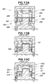
- Japanese Utility Model Laid-Open Publication No. H01-153820 proposes a draw forming method in which the periphery of a blank material is held by pressure from a blank holder, and the blank material is formed when subjected to plastic working using a metal die unit mounted on a press. This draw forming is described below with reference to FIGS. 13A through 13C hereof.
- the periphery of a blank material B is first pressed by an upper die holddown 303 of an upper die 302 and a lower die holddown 305 of a lower die 304 , and a section adjacent to the center of the blank material B is pressed by a pad 306 and a cushion 307 , as shown in FIG. 13A .
- a first draw (cylindrical section G 1 ) is formed with a punch 308 , as shown in FIG. 13B .
- a second draw (square base section G 2 ) is then formed with the cushion 307 , as shown in FIG. 13C .
- the first and second draws can thus be formed in a single step in the conventional draw forming method.
- the punch 308 is disposed on the underside of the drawing die 301
- the punch is sometimes disposed on the topside depending on the circumstances.
- the blank material B is set on the pad 306 to form draws, whereupon deflection is created in the center of the blank material B. Deflection tends to occur easily and in greater amounts particularly in cases in which the blank material is extremely thin, or in cases in which a thin blank material is hot-formed (including warm forming). As a result, there is concern that the forming dimensions will be markedly nonuniform.
- a draw forming method wherein a blank material set into a metal die unit is restrained by a blank holder and then drawn, the method comprising the steps of: setting the blank material into the metal die unit, the blank material having a stretching region and a restraint region set in the stated order outward and lined up with a drawing region that is subjected to pressure from an upper die and a lower die; restraining the restraint region of the blank material with first holder means of the blank holder; and applying tensile force to the drawing region and restraining the stretching region while second holder means of the blank holder displaces the stretching region in the shearing direction in relation to the restraint region.
- the restraint region of the blank material is restrained by the first holder means, and the stretching region of the blank material is then displaced in the shearing direction by the second holder means, whereupon tensile force is applied to the stretching region of the blank material and the drawing region in the middle, and the deflection formed in the drawing region is removed. It is therefore possible to reduce deflection in the middle of the blank material set into the metal die unit.
- a device for draw forming a blank material which device comprises: a metal die unit having an upper die and a lower die; a blank holder for restraining the blank material set in the metal die unit; and a press for applying pressure to the restrained blank material, wherein the blank holder comprises first holder means for restraining an outer peripheral section of the blank material at a first restraining position when the press is lowered; and second holder means disposed on the inside of the first holder means to restrain the inside section of the outer peripheral section of the blank material at a second restraining position when the press is further lowered.
- the press operates the first holder means, the outer peripheral section of the blank material is restrained by the first holder means, and the press is then lowered further.
- the second holder means positioned on the inside of the first holder means then stretches the middle of the blank material outward.
- the press is a double-action press
- the first restraining position is the position in which the first holder means protrudes past the second holder means and in which the blank material is held by the lowering of the double-action press
- the second restraining position is the position in which the double-action press is lowered further from the first restraining position
- the upper die is held to be capable of sliding in relation to the second holder means, and is disposed separate from an inner slider of the double-action press
- the first holder means and second holder means are fixed to an external slider positioned on the outside of the inner slider.
- first and second holder means are integrally fixed to the external slider of the double-action press, there is no movement between the external slider and the first and second holder means, and nonuniformities in the dimensions of the formed article can be reduced.
- FIG. 1 is a cross-sectional view of a draw forming device according to a first embodiment of the present invention
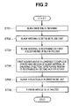
- FIG. 2 a flowchart showing the steps of a draw forming method according to the present invention
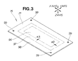
- FIG. 3 is a diagram showing the blank material used in the draw forming method of the invention.
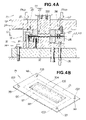
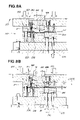
- FIGS. 4A and 4B are schematic views showing the manner in which the blank material is set on the metal die unit and restrained by first holder means in the draw forming method shown in FIG. 2 ;
- FIGS. 5A and 5B are schematic views showing the manner in which the press is lowered to displace the stretching region of the blank material upward and to remove the deflection created in the central section of the blank material;
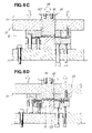
- FIGS. 6A through 6D are schematic views showing the manner in which a formed article is extracted after the formed article is obtained by drawing the central section of the blank material;
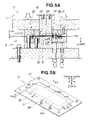
- FIG. 7 is a cross-sectional view of the draw forming device according to a second embodiment of the present invention.
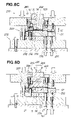
- FIGS. 8A through 8D are schematic views showing an operation of the draw forming device according to the second embodiment, and also showing the manner in which the formed article is obtained by drawing after the blank is set on a metal die unit;
- FIGS. 9A and 9B are schematic views showing the manner in which the formed article is extracted
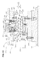
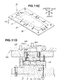
- FIG. 10 is a schematic view showing a modification of the draw forming device according to the second embodiment shown in FIG. 7 ;
- FIGS. 11A through 11D are schematic views showing the actions taken from the time the blank material is set until the time the blank material is drawn in the draw forming device in the modification;
- FIGS. 12A and 12B are schematic views showing the manner in which the formed article is extracted.
- FIGS. 13A through 13C are schematic cross-sectional views showing a conventional draw forming device.
- X indicates a horizontal axis in the longitudinal direction of a blank material 15
- Y indicates a horizontal axis orthogonal to X
- Z indicates a vertical axis orthogonal to both X and Y.
- a draw forming device 11 of the first embodiment shown in FIG. 1 is composed of a metal die unit 12 comprising an upper metal die unit 13 and a lower metal die unit 14 , and a blank holder 16 provided to the metal die unit 12 to apply pressure to the blank material 15 .
- the upper metal die unit 13 is mounted on a ram 18 of a press 17 .
- the lower metal die unit 14 is mounted on a bed 19 of the press 17 .
- the draw forming device 11 performs draw forming.
- the blank holder 16 includes first holder means 22 for restraining the outer peripheral section 21 (restraint region 98 in FIG. 3 ) of the blank material 15 , and second holder means 23 disposed on the inside (in the direction of the arrows a 1 , a 1 ) of the first holder means 22 .
- An upper cushion mechanism 24 is mounted on the upper metal die unit 13
- a lower cushion mechanism 25 is mounted on the lower metal die unit 14 in order to operate the first and second holder means 22 , 23 .
- the first holder means 22 is composed of a first upper holddown member 27 connected to the upper cushion mechanism 24 , and a first lower holddown member 28 connected to the lower cushion mechanism 25 .
- H 1 indicates the position in which the first holder means 22 restrains the blank material.
- the second holder means 23 is composed of a second upper holddown member 31 connected to the upper cushion mechanism 24 , and a second lower holddown member 32 connected to the lower cushion mechanism 25 .
- the position in which the second holder means 23 restrains the blank material is indicated by H 2 .
- the restraining position H 2 is set deeper in the shearing direction (Z-axis direction) than the restraining position H 1 of the first holder means 22 by a distance Hg.
- the upper metal die unit 13 will now be described in detail.
- the upper metal die unit 13 includes an upper base member 34 attached to the ram 18 .
- An upper die (die) 35 is attached to the center of the upper base member 34 by bolts 35 a.
- a holder placement part 36 is formed on the upper base member 34 .
- the upper metal die unit 13 includes the first upper holddown member 27 and the second upper holddown member 31 of the blank holder 16 .
- the upper cushion mechanism 24 has third cylinders 37 , 37 mounted on the upper base member 34 of the upper metal die unit 13 .
- a cushion base 41 is mounted on rods 38 , 38 of the third cylinders 37 , 37 , and is fitted over the holder placement part 36 and allowed to slide in the Z-axis direction.
- a stopper groove 44 is formed in the left side surface 43 of the cushion base 41 .
- a stopper shaft 45 that fits into the stopper groove 44 is mounted on the upper base member 34 .
- the operation of the third cylinders 37 , 37 causes the cushion base 41 to slide in the Z-axis direction irrespective of the movement of the ram 18 .
- the third cylinders 37 have a structure for storing fluid, for example. Rubber, a compressed spring, or another such elastic member (cushion member) can be used instead of the fluid-storing cylinders.
- the rods 38 are used in place of pins in this case.
- the first upper holddown member 27 has a holddown main body 51 .
- the holddown main body 51 has a pressure surface 54 formed on the underside, and a recessed hole 55 formed in the pressure surface 54 .
- the reference numeral 56 indicates a bolt for fastening the first upper holddown member 27 to the cushion base 41 .
- the second upper holddown member 31 has a holddown main body 58 that faces the second lower holddown member 32 .
- the holddown main body 58 has a pressure surface 61 formed on the underside.
- the pressure surface 61 is located deeper (upward) than the pressure surface 54 of the first upper holddown member 27 by a distance Hg.
- the upper die 35 has a die surface 67 formed at the bottom of an upper die main body 65 .
- the lower metal die unit 14 will now be described in detail.
- the lower metal die unit 14 includes a lower base member 72 provided to the bed 19 of the press 17 .
- the lower base member 72 includes a lower die 73 in the center of the base member.
- the lower metal die unit 14 includes the first lower holddown member 28 and second lower holddown member 32 of the blank holder 16 .
- the lower cushion mechanism 25 has first cylinders 75 , 75 and second cylinders 76 , 76 mounted on the lower base member 72 .
- Rods, 77 , 77 , 78 , 78 of the first and second cylinders 75 , 76 are all connected to the first and second lower holddown members 28 , 32 .
- First guide shafts 81 , 81 for guiding the first lower holddown member 28 and second guide shaft 82 for guiding the second lower holddown member 32 are mounted on the lower base member 72 .
- the first cylinders 75 have a structure for storing fluid, for example. Rubber, a compressed spring, or another such elastic member (cushion member) can be used instead of the fluid-storing cylinders.
- the rods 77 are used in place of pins in this case.
- the second cylinders 76 have a structure for storing fluid, for example. Rubber, a compressed spring, or another such elastic member (cushion member) can be used instead of the fluid-storing cylinders.
- the rods 78 are used in place of pins in this case.
- the first lower holddown member 28 faces the first upper holddown member 27 , and the rods 77 , 77 of the first cylinders 75 , 75 are connected to the underside of a holddown main body 83 .
- the holddown main body 83 has guide holes 84 , 84 into which the first guide shafts 81 , 81 are fitted, and these shafts are allowed to slide in the Z-axis direction.
- the top surface of the holddown main body 83 constitutes a pressure surface 85 .
- the blank material 15 is firmly held by the pressure surface 85 and the pressure surface 54 facing the pressure surface 85 .
- the blank is set on the first lower holddown member 28 at the position indicated by U 1 .
- the blank setting position U 1 and the pressure surface 85 are located higher than a die surface 92 of the lower die 73 by a distance H 3 .
- the second lower holddown member 32 faces the second upper holddown member 31 , and the rods 78 , 78 of the second cylinders 76 , 76 are connected to the underside of a holddown main body 86 .
- the holddown main body 86 has guide holes 87 , 87 into which the second guide shaft 82 are fitted, and these shafts are allowed to slide in the Z-axis direction.
- the top surface of the holddown main body 86 constitutes a pressure surface 88 .
- the blank material 15 is firmly held by the pressure surface 88 and the pressure surface 61 facing the pressure surface 88 . This is described in further detail hereinafter.
- the position of the pressure surface 88 is the same as that of the pressure surface 85 of the first lower holddown member 28 located on the outside of the pressure surface 88 , and is set to the blank setting position U 1 .
- the die surface 92 is formed on the top surface of a lower die main body 91 of the lower die 73 .
- the blank material 15 is formed into the desired shape by the die surface 92 of the lower die 73 and the die surface 67 of the upper die 35 .
- the second lower holddown member 32 is raised above the die surface 92 , whereby the blank material 15 can be formed into the desired shape as shown in FIG. 5A .
- the lower die 73 has four setting shafts 103 .
- the number of cylinders and guide shafts (including guide holes) in the blank holder 16 provided to the metal die unit 12 is arbitrary.
- FIG. 2 shows a flowchart of the draw forming method according to the first embodiment of the present invention.
- ST02 The blank material 15 is set on the metal die unit 12 , which is mounted on the press 17 in advance.
- the first holder means 22 is lowered, whereby the second holder means 23 displaces the stretching region 97 (see FIG. 3 ) of the blank material 15 relative to the restraint region 98 in the shearing direction, and restrains the stretching region 97 .
- This displacement causes tensile force to be applied to a drawing region 96 (see FIG. 3 ) of the blank material 15 .
- a drawing force is applied to the drawing region 96 (see FIG. 3 ), and the region is subjected to plastic working by the upper die 35 and the lower die 73 , whereby the blank material 15 is formed (see FIG. 6B ).
- FIG. 3 shows the first step of the forming method in ST01 shown in FIG. 2 .
- the blank material 15 is obtained in the first step.
- the blank material 15 is a plate member (material) including a stretching region 97 and a restraint region 98 disposed in the stated order outward from the drawing region 96 (in the direction of the arrows a 3 , a 3 ).
- four fitting holes 99 are formed in the restraint region 98 .
- the four aforementioned setting shafts 103 are fitted into the four fitting holes 99 .
- the restraint region 98 is the outer peripheral section 21 of the blank material 15 .
- FIGS. 4A and 4B show the second step of the draw forming method of the first embodiment, and also show the details of ST02 and ST03 shown in FIG. 2 .
- the blank material 15 is set on the metal die unit 12 in the second step shown in FIG. 4A .
- the metal die unit 12 is opened as shown in FIG. 1 , the four setting shafts 103 are fitted into the four fitting holes 99 of the blank material 15 shown in FIG. 3 , and the blank material 15 is set on the first lower holddown member 28 of the first holder means 22 and the second lower holddown member 32 of the second holder means 23 .
- the first holder means 22 of the blank holder 16 restrains the restraint region 98 in the second step.
- the press 17 is operated to lower the upper metal die unit 13 by a stroke S 1 as shown in FIG. 4A , the first upper holddown member 27 is pressed against the blank material 15 with a pressure Ph, and the blank material 15 is restrained by the first upper holddown member 27 and first lower holddown member 28 with a specific surface pressure.
- the closed restraining position H 1 of the first holder means 22 coincides with the blank setting position U 1 at this time.
- the pressure Ph is transmitted to the first upper holddown member 27 via the third cylinders 37 , 37 of the upper cushion mechanism 24 .
- the central section 104 of the blank material 15 is not supported, and deflection 105 occurs in the central section 104 as shown in FIG. 4B .
- the first holder means 22 restrains the restraint region 98 of the blank material 15 in which deflection 105 has occurred in the central section 104 .
- FIGS. 5A and 5B show the third step of the draw forming method of the first embodiment, and also show the details of ST04 shown in FIG. 2 .
- step S 3 the restraint region 98 of the blank material 15 is restrained, and the second holder means 23 of the blank holder 16 displaces the stretching region 97 in relation to the restraint region 98 in the shearing direction (the direction of the arrow a 4 , and the Z-axis direction).
- Tensile force is thereby applied to the drawing region 96 as shown by the arrow a 5 , and the drawing region is then restrained. In other words, tensile force is applied radially outward to the drawing region 96 in an amount proportional to the amount of displacement.
- the press 17 operates and lowers the first holder means 22 while still restraining the blank material 15 , and the stretching region 97 of the blank material 15 is pressed against the second lower holddown member 32 .
- the second lower holddown member 32 is stationary at this time.
- the first holder means 22 is then lowered by a distance H 4 from the blank setting position U 1 , and the restraining position H 1 of the first holder means 22 is lowered by a distance H 4 .
- the stretching region 97 is displaced by a distance H 4 from the restraining position H 1 of the first holder means 22 , and the second holder means 23 is stopped at the restraining position H 2 while the second lower holddown member 32 and the second upper holddown member 31 restrain the stretching region 97 .
- FIGS. 6A through 6D show the plastic working step in ST05 and the extraction of the formed article in ST06, shown in FIG. 2 .
- the upper metal die unit 13 is lowered to lower the first and second holder means 22 , 23 by a stroke S 3 , as shown in FIG. 6A .
- the upper metal die unit 13 is lowered against resistance from the first cylinders 75 , 75 and the second cylinders 76 , 76 , and the drawing region 96 of the blank material 15 is pressed against the die surface 92 of the lower die 73 .
- the upper metal die unit 13 is lowered by a stroke S 3 , whereupon the first and second holder means 22 , 23 come into contact with the lower base member 72 and stop.
- the upper die 35 is then lowered and pressed against the blank material 15 , whereby the blank material is drawn into the desired shape, as shown in FIG. 6B .
- the upper base member 34 is lowered to apply a draw force Pm to the drawing region 96 of the blank material 15 through the upper die 35 , and the drawing region 96 is plastically deformed by the lower die 73 , whereby the formed article 107 is obtained.
- the upper base member 34 is raised, whereby only the upper die 35 rises in the direction of the arrow a 6 , and the upper die 35 separates from the formed article 107 .
- the entire upper metal die unit 13 is then raised, whereby the formed article 107 is lifted and separated from the lower die 73 , as shown in FIG. 6D . Consequently, the first and second holder means 22 , 23 open, and the operator is therefore able to extract the formed article 107 .
- a blank material 15 is obtained in the first step of the draw forming method in the first embodiment, as described above.
- This blank material includes a stretching region 97 and a restraint region 98 disposed in the stated order outward from the drawing region 96 , as shown in FIG. 3 .
- the blank material 15 is set on the metal die unit 12 , and the restraint region 98 is restrained by the first holder means 22 of the blank holder 16 , as shown in FIG. 4A .
- the stretching region 97 is forcibly displaced in the shearing direction by the second holder means 23 of the blank holder 16 as shown in FIG. 5A , whereby tensile force is applied to the drawing region 96 .
- the tensile force does not result in deflection 105 in the drawing region 96 . It is therefore possible to reduce deflection in the central section 104 of the blank material 15 set on the metal die unit 12 .
- the draw forming device 11 shown in FIG. 1 includes the blank holder 16 , which comprises the first holder means 22 for restraining the outer peripheral section 21 of the blank material 15 at the first restraining position H 1 , and the second holder means 23 for restraining the inner section of the outer peripheral section 21 of the blank material 15 at the second restraining position H 2 when the press 17 is lowered. Therefore, after the outer peripheral section 21 is restrained, the inner section of the outer peripheral section 21 is restrained by the second holder means 23 so as to be displaced.
- the central section 104 of the blank material 15 is thereupon stretched outward as shown by the arrow a 5 (see FIG. 5 ). As a result, deflection is reduced in the central section 104 of the blank material 15 , and drawing can be performed with minimal nonuniformities in the formed dimensions.
- a double-action press 217 is used as the press 17 shown in FIG. 1 .
- a draw forming device 211 of the second embodiment shown in FIG. 7 is composed of a metal die unit 212 comprising an upper metal die unit 213 and a lower metal die unit 214 , and a blank holder 216 provided to the metal die unit 212 to hold down the blank material 15 .
- the upper metal die unit 213 is mounted on the double-action press 217 .
- the lower metal die unit 214 is mounted on a bed 219 .
- the double-action press 217 includes an inner slider 245 for applying pressing force in order to form the blank material 15 , and an external slider 246 disposed on the outside of the inner slider 245 to hold down the blank material 15 .
- the external slider 246 is raised and lowered individually by hydraulic pressure, for example.
- the upper metal die unit 213 is composed of an upper base member 234 integrally mounted on the external slider 246 of the double-action press 217 , and an upper die 235 disposed inside an open section 247 formed in the center of the upper base member 234 .
- the lower metal die unit 214 is composed of a lower base member 272 mounted on the bed 219 , and a lower die 273 fixed in the center of the lower base member 272 .
- the blank holder 216 is composed of first holder means 222 for restraining the outer peripheral section 21 of the blank material 15 shown in FIG. 3 , and second holder means 223 disposed on the inside of the first holder means 222 .
- the first holder means 222 includes a first upper holddown member 227 integrally fixed to the upper base member 234 by bolts 256 , and a first lower holddown member 228 that is mounted on the lower base member 272 by first cylinders 275 and is allowed to slide in the Z-axis direction.
- the first upper holddown member 227 has a holddown member main body 251 , which is formed into a rectangular shape large enough to come into contact with the outer peripheral section 21 of the blank material 15 .
- the holddown member main body 251 has a pressure surface 254 formed on the underside, and a recessed hole 255 formed so that the pressure surface 254 is open.
- the pressure surface 254 reaches the restraining position H 1 of the first holder means 222 and holds down the upper surface of the outer peripheral section 21 of the blank material 15 .
- the restraining position H 1 is the position in which the first holder means 222 protrudes past the second holder means 223 ; i.e., where the first holder means is lowered to hold the blank material 15 .
- the first lower holddown member 228 has a holddown member main body 283 that is formed into a rectangular shape and that faces the holddown member main body 251 of the first upper holddown member 227 .
- the holddown member main body 283 has a pressure surface 285 formed on the topside to press on the underside of the blank material 15 .
- the pressure surface 285 is provided with four setting shafts 203 for setting the blank material 15 .
- the holddown member main body 283 also has guide holes 284 , 284 into which first guide shafts 281 , 281 are fitted and allowed to slide in the Z-axis direction by means of a collar 283 a.
- the first guide shafts 281 , 281 are mounted on the lower base member 272 .
- the first cylinders 275 , 275 are mounted on the lower base member 272 , and the distal ends of the rods of the first cylinders 275 , 275 are connected to the holddown member main body 283 , whereby the first lower holddown member 228 supports the underside of the blank material 15 .
- the first guide shafts 281 , 281 guide the first lower holddown member 228 vertically (in the Z-axis direction).
- the entire lengths of the first guide shafts 281 , 281 can be limited so as to not protrude from the pressure surface 285 of the first lower holddown member 228 , for example.
- the recessed hole 255 is optionally provided to the first upper holddown member 227 to allow the insertion and withdrawal of the first guide shafts 281 , 281 .
- the second holder means 223 includes a second upper holddown member 231 integrally fixed to the upper base member 234 by bolts (not shown), and a second lower holddown member 232 that is mounted on the lower base member 272 and is allowed to slide in the Z-axis direction by means of the lower base member 272 .
- the second upper holddown member 231 has a holddown member main body 258 formed into a rectangular shape corresponding to the size of the stretching region 97 , which is an extension of the inside of the outer peripheral section 21 of the blank material 15 shown in FIG. 3 .
- the underside of the holddown member main body 258 constitutes a pressure surface 261 for pressing on the stretching region 97 .
- the top of the holddown member main body 258 is provided with a hole 263 into which a guide post 262 is fitted, first elastic member mounting holes 265 into which elastic members 264 are fitted, and a mounting hole 269 for mounting a stopper member 268 .
- the pressure surface 261 of the second upper holddown member 231 reaches the restraining position H 2 of the second holder means 223 and holds down the topside of the blank material 15 .
- the mounting shape of the guide post 262 and the hole 263 for fitting the guide post 262 constitute one example, and another possibility, for example, is to not form the hole 263 and to fasten the guide post 262 with bolts.
- the pressure surface 261 of the second upper holddown member 231 is positioned above the pressure surface 254 of the first upper holddown member 227 at a distance Hg.
- the second lower holddown member 232 has a holddown member main body 286 that is formed into a rectangular shape and that faces the holddown member main body 258 of the second upper holddown member 231 , a pressure surface formed on the topside of the holddown member main body 286 , a guide hole 287 formed so as to open towards the bottom of the holddown member main body 286 , and a second guide shaft 282 that fits into the guide hole 287 by means of a collar 286 a.
- the second guide shaft 282 is mounted on the lower base member 272 .
- Second cylinders 276 , 276 are mounted on the lower base member 272 .
- the top ends of the rods of the second cylinders 276 , 276 are connected to the lower ends of the second lower holddown member 232 .
- first upper holddown member 227 and the first lower holddown member 228 are formed into rectangular shapes in this example. However, these shapes are arbitrary and can also be circular. The same applies to the second upper holddown member 231 and the second lower holddown member 232 .
- the upper die 235 has an upper die main body 236 , which has a die surface 237 on the underside.
- a supporting member 238 is provided in the central part of the upper die main body 236 .
- a guide hole 239 is formed in the supporting member 238 , and the guide post 262 is slidably fitted into the guide hole 239 by means of a collar 240 .
- Second elastic member mounting holes 241 are formed in the supporting member 238 .
- the other ends (upper ends) of the aforementioned elastic members 264 are fitted into the second elastic member mounting holes 241 .
- the supporting member 238 has a return-restricting section 242 .
- the return-restricting section 242 has a hole for receiving the stopper member 268 .
- the stopper member 268 is mounted using a bolt 243 in the mounting hole 269 formed in the second upper holddown member 231 .
- the topside of the upper die main body 82 constitutes a contact surface 94 that comes into contact with the underside of the inner slider 245 .
- the elastic members 264 are composed, e.g., of compression springs that urge the upper die 235 in the Z-axis direction into standby mode.
- the return-restricting section 242 holds the die surface 237 at a position separated upward from the pressure surface 261 of the second upper holddown member 231 by a distance M.
- the lower die 273 has a die surface 292 that faces the die surface 237 of the upper die 235 .
- the upper die 235 is supported to be capable of sliding in relation to the second holder means 223 , and is disposed so as to be separated from the inner slider 245 of the double action double-action press 217 .
- the first and second holder means 222 , 223 are fixed to the external slider 246 .
- FIGS. 8A through 8D The following is a description, made with reference to FIGS. 8A through 8D , of the operation whereby the blank material 15 shown in FIG. 3 is drawn by the draw forming device 211 of the second embodiment shown in FIG. 7 .
- the blank material 15 is set on the metal die unit 212 .
- the metal die unit 212 is opened, the four setting shafts 203 (see FIG. 7 ) are fitted into the four fitting holes 99 (see FIG. 3 ) in the blank material 15 , and the blank material 15 is set on the first lower holddown member 228 and the second lower holddown member 232 .
- the external slider 246 of the double-action press 217 is lowered, whereby the first upper holddown member 227 and the second upper holddown member 231 are lowered as shown in FIG. 8A .
- the first upper holddown member 227 reaches the outer peripheral section 21 of the blank material 15 , and the pressure surface 254 on the underside of the first upper holddown member 227 presses on the outer peripheral section 21 .
- Combining the outputs of the double-action press 217 and the first cylinders 275 allows the first holder means 222 (first upper holddown member 227 and first lower holddown member 228 ) to restrain the outer peripheral section 21 of the blank material 15 at the restraining position H 1 of the first holder means 222 .
- the drawing region 96 of the central section 104 in the blank material 15 is not supported, and deflection 105 occurs in the central section 104 of the blank material 15 as described in FIG. 4B .
- the external slider 246 further lowers the first holder means 222 by a stroke Sa 1 against resistance from the output of the first cylinders 275 , whereupon a pressure surface 288 on the topside of the second lower holddown member 232 is raised by a stroke Sa 1 as a result, and the stretching region 97 of the blank material 15 is displaced upward from the outer peripheral section 21 by a distance H 4 (see FIG. 5B ) that corresponds to the stroke Sa 1 .
- the output of the second cylinders 276 at this time is greater than the output of the double-action press 217 , and the second cylinders 276 stop without being lowered.
- the second lower holddown member 232 displaces the stretching region 97 of the blank material 15 while the outer peripheral section 21 of the blank material 15 is restrained.
- the drawing region 96 and the stretching region 97 are therefore stretched in the X- and Y-axis directions as indicated by the arrows a 5 , and the deflection 105 (see FIG. 4B ) is removed from in the central section 104 of the blank material 15 .
- the blank material 15 is displaced, and the stretching region 97 of the blank material 15 is restrained by the pressure surface 261 of the second upper holddown member 231 and the pressure surface 288 of the second lower holddown member 232 .
- the output of the double-action press 217 and the second cylinders 276 allows the second holder means 223 (the second upper holddown member 231 and the second lower holddown member 232 ) to restrain the blank material 15 at the restraining position H 2 of the second holder means 223 .
- the second upper holddown member 231 of the second holder means 223 does not move in the Z-axis direction independent of the external slider 246 , because the first and second holder means 222 , 223 are fixed to the external slider 246 . Therefore, nonuniformities are reduced in the dimensions of the formed article.
- the second holder means 223 is also lowered, and the entire drawing region 96 of the blank material 15 is deformed by the die surface 292 of the lower die 273 .
- the first lower holddown member 228 and the second lower holddown member 232 come into contact with the lower base member 272 and stop.
- the outer peripheral section 21 and stretching region 97 of the blank material 15 are restrained by the first holder means 222 and the second holder means 223 .
- the inner slider 245 is lowered based on information about the position of the external slider 246 , whereupon the underside of the inner slider 245 comes into contact with a contact surface 244 of the upper die 235 , the upper die 235 is lowered against the repulsive force of the elastic members 264 , and the upper die applies pressure to the drawing region 96 of the blank material 15 .
- the drawing region 96 of the blank material 15 is drawn into the desired shape by the die surface 237 of the upper die 235 and the die surface 292 of the lower die 273 , and the formed article 107 is obtained.
- FIGS. 9A and 9B show the operation of extracting the formed article 107 obtained by drawing.
- the inner slider 245 is raised in FIG. 9A , whereupon the repulsive force of the elastic members 264 raises the upper die 235 .
- the stopper member 268 comes into contact with the return-restricting section 242 , the upper die 235 reaches an upper limit, and the device goes into standby mode.
- the external slider 246 continues to apply pressure.
- the second lower holddown member 232 reaches an upper limit and stops at the stroke end of the second cylinders 276 , and the second holder means 223 opens.
- the formed article 107 separates from the die surface 292 of the lower die 273 in this step.
- the rods of the first cylinders 275 are raised further, and the first lower holddown member 228 stops at an upper limit at the stroke end of the first cylinders 275 .
- the first holder means 222 opens and the operator extracts the formed article 104 .
- pressing the “start button” on the operating panel of the double-action press 17 automatically executes the operation in FIGS. 7 through 9B , and the operator extracts the formed article 104 , whereby one formation cycle is completed.
- tensile force is applied to the central section 104 of the blank material 15 connected to the stretching region 97 .
- the tensile force is applied from the time the outer peripheral section 21 of the blank material 15 is restrained at the restraining position H 1 of the first holder means 222 until the time the stretching region 97 of the blank material 15 is restrained at the restraining position H 2 of the second holder means 223 .
- the deflection in the central section 104 of the blank material 15 can be removed.
- the upper die 235 is supported by the elastic members 264 , is allowed to slide (in the Z-axis direction) in relation to the second holder means 223 , and is disposed separate from the inner slider 245 of the double-action press 217 .
- the upper die is therefore operated using the second holder means 223 as a reference. Accordingly, the upper die 235 can be positioned with greater accuracy.
- FIG. 10 shows a modified example of the draw forming device 211 of the second embodiment shown in FIG. 7 .
- components identical to those in the draw forming device of the second embodiment are denoted by the same reference numerals, and detailed descriptions are omitted.
- the draw forming device 211 A of the modified example has a metal die unit 212 A comprising an upper metal die unit 213 A and a lower metal die unit 214 A, and also has a blank holder 216 A disposed on the metal die unit 212 A to restrain the blank material 15 .
- the upper metal die unit 213 A has an upper die 235 A disposed in an open section 247 formed in the upper base member 234 .
- the lower metal die unit 214 A has a lower die 273 mounted on a lower base member 272 A, which is mounted on a bed 219 .
- the lower base member 272 A is mounted on the bed 219 .
- a blank holder 216 A includes first holder means 222 , and second holder means 223 A disposed on the inside thereof.
- the restraining position H 1 of the first holder means 222 is located farther out than the second holder means 223 A, and is the position in which the blank material 15 is held. The details are described hereinafter.
- the second holder means 223 A has a second lower holddown member 232 A fixed to the lower base member 272 A.
- the restraining position Hb 2 of the second holder means 223 A is the position in which the double-action press 17 is lowered past the restraining position H 1 of the first holder means 222 by a stroke Sb 1 .
- the blank material 15 is restrained at a position that is lower by a stroke Sb 1 than the restraining position H 1 of the first holder means 222 .
- the second lower holddown member 232 A has a holddown member main body 286 A formed into a rectangular shape facing the holddown member main body 258 of the second upper holddown member 231 .
- the holddown member main body 286 A has a pressure surface 288 on the topside.
- first upper holddown member 227 , first lower holddown member 228 , second upper holddown member 231 , and second lower holddown member 232 A are rectangular in this description, but the shapes of these components are arbitrary and may also be circular.
- the upper die 235 A has an upper die main body 236 A.
- the elastic members 264 are composed, e.g., of compression springs that urge the upper die 235 in the Z-axis direction into standby mode.
- the upper die 235 A is supported to be capable of sliding in relation to the second holder means 223 A.
- the upper die 235 A is also disposed so as to be separated from the inner slider 245 of the double action double-action press 217 .
- the first holder means 222 and second holder means 223 A are fixed integrally to the external slider 246 of the double-action press 217 .
- the descending stroke Sb 1 of the first holder means 222 of the modified example which is necessary to restrain the outer peripheral section 21 of the blank material 15 , is greater than the descending stroke Sa 1 of the second embodiment shown in FIG. 7 . Therefore, the displaced depth H 5 of the stretching region 97 of the blank material 15 , described later, is greater than the displaced depth in the second embodiment. In other words, the amount of displacement is greater, and the stretching region 97 and drawing region 96 of the blank material 15 are subjected to a tensile force that corresponds to the amount of displacement. Therefore, deflection in the central section of the blank material 15 is reduced.
- the blank material 15 is set in the opened metal die unit 212 A as shown in FIG. 10 , the blank material 15 is set on the first lower holddown member 228 and second lower holddown member 232 A as previously described.
- lowering the external slider 246 of the double-action press 217 causes the first upper holddown member 227 and the second upper holddown member 231 to be lowered, whereupon the first upper holddown member 227 reaches the outer peripheral section 21 of the blank material 15 , and the pressure surface 254 of the first upper holddown member 227 applies pressure to the outer peripheral section 21 .
- the output of the double-action press 217 and of the first cylinders 275 allows the first holder means 222 to restrain the outer peripheral section 21 of the blank material 15 at the restraining position H 1 .
- the blank material 15 is restrained at the external peripheral section 21 in the restraining position H 1 , and is not supported at the drawing region 96 in the central section 104 .
- Deflection 105 is formed in the central section 104 of the blank material 15 , as shown in FIG. 4B .
- the external slider 246 of the double-action press 217 is then lowered as shown in FIG. 11B , whereupon the first holder means 222 for restraining the outer peripheral section 21 of the blank material 15 is lowered by a stroke Sb 1 against resistance from the output of the first cylinders 275 , and the first lower holddown member 228 of the first holder means 222 comes into contact with the lower base member 272 A and stops.
- the lowering of the first holder means 222 causes the stretching region 97 of the blank material 15 to be displaced upward from the outer peripheral section 21 of the blank material 15 , which is restrained by the first holder means 222 .
- This displacement causes the stretching region 97 and the drawing region 96 of the blank material 15 to be stretched outward.
- the stretching region 97 of the blank material 15 is then restrained by the second holder means 223 A.
- the second upper holddown member 231 and the second lower holddown member 232 A of the second holder means 223 A restrain the stretching region 97 of the blank material 15 at the restraining position Hb 2 , which is set to the position in which the external slider 246 is lowered by a stroke Sb 1 .
- the external slider 246 continues to apply pressure, whereby the first holder means 222 and second holder means 223 A continue to restrain the outer peripheral section 21 and the stretching region 97 of the blank material 15 .
- the inner slider 245 is lowered based on information about the position of the external slider 246 as shown in FIG. 11D , whereupon the underside of the inner slider 245 comes into contact with the contact surface 244 of the upper die 235 A, and the upper die 235 A is lowered against the repulsive force of the external slider 246 to apply pressure to the drawing region 96 of the blank material 15 .
- the drawing region 96 of the blank material 15 is drawn into the desired shape by the die surface 237 of the upper die 235 A, and the die surface 292 of the lower die 273 , and a formed article 107 A is obtained.
- the external slider 246 then continues to be raised as shown in FIG. 12B , whereupon the rods of the first cylinders 275 are raised as well, and the first upper holddown member 227 and first lower holddown member 228 of the first holder means 222 are raised while the outer peripheral section 21 of the blank material 15 is restrained. As a result, the blank material 15 moves upward away from the pressure surface 288 of the second lower holddown member 232 A. The first lower holddown member 228 reaches an upper limit and stops at the stroke end of the first cylinders 275 .
- the external slider 246 is then raised further, whereupon the first holder means 222 opens as shown in FIG. 10 , and the operator therefore extracts the formed article 107 A.
- pressing the “start button” on the operating panel of the double-action press 17 automatically executes the operation beginning with drawing the blank material 15 and ending with opening the metal die unit, and the operator extracts the formed article 107 A, whereby one formation cycle is completed.
- a draw forming device of a modified example was described above, but according to this draw forming device of the modified example, settings are selected so that there is an increase in the descending stroke Sb 1 of the first holder means 222 of the modified example necessary to restrain the outer peripheral section 21 of the blank material 15 .
- the displacement of the stretching region 97 of the blank material 15 is therefore proportionally greater, and the stretching region 97 and drawing region 96 of the blank material 15 are stretched farther.
- the deflection in the central section of the blank material 15 is therefore further reduced.
- the outer peripheral section of a blank material is restrained by first holder means, and the stretching region on the inside of the outer peripheral section is displaced and restrained in the shearing direction relative to the outer peripheral section.
- Tensile force is thereby applied to the drawing region in the middle of the blank material, and deflection in the drawing region is reduced.
Landscapes
- Engineering & Computer Science (AREA)
- Mechanical Engineering (AREA)
- Shaping Metal By Deep-Drawing, Or The Like (AREA)
Applications Claiming Priority (5)
| Application Number | Priority Date | Filing Date | Title |
|---|---|---|---|
| JP2004339409A JP2006142371A (ja) | 2004-11-24 | 2004-11-24 | 絞り成形方法及び絞り成形装置 |
| JP2004-339409 | 2004-11-24 | ||
| JP2005-303306 | 2005-10-18 | ||
| JP2005303306A JP2006255781A (ja) | 2005-02-16 | 2005-10-18 | 絞り成形装置 |
| PCT/JP2005/021176 WO2006057196A1 (fr) | 2004-11-24 | 2005-11-11 | Procede et dispositif de formation d'etirement |
Publications (1)
| Publication Number | Publication Date |
|---|---|
| US20080098789A1 true US20080098789A1 (en) | 2008-05-01 |
Family
ID=36497934
Family Applications (1)
| Application Number | Title | Priority Date | Filing Date |
|---|---|---|---|
| US11/718,052 Abandoned US20080098789A1 (en) | 2004-11-24 | 2005-11-11 | Draw Forming Method and Device |
Country Status (4)
| Country | Link |
|---|---|
| US (1) | US20080098789A1 (fr) |
| CA (1) | CA2586049C (fr) |
| DE (1) | DE112005002868B4 (fr) |
| WO (1) | WO2006057196A1 (fr) |
Cited By (23)
| Publication number | Priority date | Publication date | Assignee | Title |
|---|---|---|---|---|
| US20090241628A1 (en) * | 2008-03-25 | 2009-10-01 | Ford Global Technologies, Llc | Draw Die and Method of Manufacturing Same |
| US20100050729A1 (en) * | 2008-09-01 | 2010-03-04 | Rahul Kulkarni | Die assembly for use in an apparatus for forming a workpiece |
| US20100064759A1 (en) * | 2008-09-18 | 2010-03-18 | Benteler Automobiltechnik Gmbh | Method and device for press-hardening a metallic formed structure |
| US20100201031A1 (en) * | 2007-11-30 | 2010-08-12 | Toyota Jidosha Kabushiki Kaisha | Mold for press apparatus, and open-drawing method |
| US20100251799A1 (en) * | 2009-04-07 | 2010-10-07 | Rexam Beverage Can Company | Tooling pod for double action can end press |
| CN102319799A (zh) * | 2011-06-29 | 2012-01-18 | 无锡市中捷减震器有限公司 | 汽车减震器内支撑管的侧滑块切边模具 |
| CN102319798A (zh) * | 2011-06-29 | 2012-01-18 | 无锡市中捷减震器有限公司 | 折弯冲侧孔的冲压复合模具 |
| CN102319801A (zh) * | 2011-07-04 | 2012-01-18 | 无锡市中捷减震器有限公司 | 弹性夹内斜楔式弯曲模 |
| US20120090768A1 (en) * | 2009-04-14 | 2012-04-19 | Airbus Operations Gmbh | Apparatus and method for draping knitted fiber fabrics for curved profiled structural parts of fiber composite material |
| CN102847802A (zh) * | 2012-09-12 | 2013-01-02 | 无锡红旗船厂有限公司 | 高强度薄钢板上压制加强筋的成型模具 |
| US20130098132A1 (en) * | 2011-10-21 | 2013-04-25 | Bor-Tsuen Lin | Punch with groove structure, and micro-drawing device using the same |
| US20130213108A1 (en) * | 2012-02-20 | 2013-08-22 | Richard Paul KNERR | Method of making a stamped part |
| WO2013139731A1 (fr) * | 2012-03-22 | 2013-09-26 | Allgaier Werke Gmbh | Dispositif et procédé pour usiner une pièce en métal, en particulier pour fabriquer un élément en forme de pot pour l'industrie automobile et pièce correspondante |
| US8984927B2 (en) | 2010-12-22 | 2015-03-24 | Toyota Jidosha Kabushiki Kaisha | Die for machine press |
| US20150107321A1 (en) * | 2013-10-21 | 2015-04-23 | Ford Global Technologies, Llc | Deep Draw Manufacturing Process |
| FR3018709A1 (fr) * | 2014-03-20 | 2015-09-25 | Peugeot Citroen Automobiles Sa | Outillage d'emboutissage pour la conformation d'une piece emboutie |
| US20160107280A1 (en) * | 2014-10-15 | 2016-04-21 | Fu Ding Electronical Technology (Jiashan) Co.,Ltd. | Press mechanism |
| US20160207093A1 (en) * | 2013-09-30 | 2016-07-21 | ALLGAIER WERK GmbH | Device for forming a sheet-metal workpiece |
| US9724745B2 (en) | 2009-08-26 | 2017-08-08 | Toyota Jidosha Kabushiki Kaisha | Press forming method |
| US20180043421A1 (en) * | 2016-08-12 | 2018-02-15 | GM Global Technology Operations LLC | Indexing self-aligning hardware tool |
| US20200197997A1 (en) * | 2018-12-19 | 2020-06-25 | Dajun Zhou | Stretch forming die |
| US20230249239A1 (en) * | 2020-06-29 | 2023-08-10 | Toyota Boshoku Kabushiki Kaisha | Workpiece production apparatus |
| CN119500885A (zh) * | 2024-12-23 | 2025-02-25 | 中航西安飞机工业集团股份有限公司 | 一种大型深腔盆形件双动拉深模具及交替拉深方法 |
Families Citing this family (6)
| Publication number | Priority date | Publication date | Assignee | Title |
|---|---|---|---|---|
| CN101428482B (zh) * | 2008-12-05 | 2010-09-08 | 北京康迪普瑞模具技术有限公司 | 一种精密异型薄壁压边圈的制作方法 |
| DE102009053366A1 (de) * | 2009-11-14 | 2011-05-19 | Bayerische Motoren Werke Aktiengesellschaft | Verfahren zur Herstellung eines Profilbauteils aus einem Blechmaterial |
| DE102009053365A1 (de) * | 2009-11-14 | 2011-05-19 | Bayerische Motoren Werke Aktiengesellschaft | Verfahren zur Herstellung eines einbaufertigen komplexen Blechformteils |
| DE102013201613A1 (de) * | 2013-01-31 | 2014-07-31 | Thyssenkrupp System Engineering Gmbh | Verfahren und System zur Herstellung einer Baugruppe |
| JP7155578B2 (ja) * | 2018-03-30 | 2022-10-19 | マツダ株式会社 | 加工装置及び方法 |
| JP7403794B2 (ja) * | 2019-11-07 | 2023-12-25 | 太陽工業株式会社 | 複動プレス金型 |
Citations (2)
| Publication number | Priority date | Publication date | Assignee | Title |
|---|---|---|---|---|
| US6830419B1 (en) * | 2000-11-20 | 2004-12-14 | Alfons Haar Inc. | Aerosol can ends |
| US7237423B1 (en) * | 2004-11-12 | 2007-07-03 | Miller Tool And Die Company Inc. | Apparatus for stretch forming blanks |
Family Cites Families (5)
| Publication number | Priority date | Publication date | Assignee | Title |
|---|---|---|---|---|
| JPS5376965A (en) * | 1976-12-20 | 1978-07-07 | Toyota Motor Co Ltd | Construction of swaging die |
| CH621271A5 (fr) * | 1977-06-15 | 1981-01-30 | Aluminiumwerke Ag Rorschach | |
| JPS55103231A (en) * | 1979-02-01 | 1980-08-07 | Toyota Motor Corp | General purpose drawing die structure of double acting press |
| JPS59175428U (ja) * | 1983-05-11 | 1984-11-22 | 日産自動車株式会社 | ダブルアクシヨンプレス型 |
| JPH01153820U (fr) * | 1988-04-08 | 1989-10-23 |
-
2005
- 2005-11-11 CA CA2586049A patent/CA2586049C/fr not_active Expired - Fee Related
- 2005-11-11 WO PCT/JP2005/021176 patent/WO2006057196A1/fr not_active Ceased
- 2005-11-11 DE DE112005002868T patent/DE112005002868B4/de not_active Expired - Fee Related
- 2005-11-11 US US11/718,052 patent/US20080098789A1/en not_active Abandoned
Patent Citations (2)
| Publication number | Priority date | Publication date | Assignee | Title |
|---|---|---|---|---|
| US6830419B1 (en) * | 2000-11-20 | 2004-12-14 | Alfons Haar Inc. | Aerosol can ends |
| US7237423B1 (en) * | 2004-11-12 | 2007-07-03 | Miller Tool And Die Company Inc. | Apparatus for stretch forming blanks |
Cited By (40)
| Publication number | Priority date | Publication date | Assignee | Title |
|---|---|---|---|---|
| US8490455B2 (en) * | 2007-11-30 | 2013-07-23 | Toyota Jidosha Kabushiki Kaisha | Mold for press apparatus, and open-drawing method |
| US20100201031A1 (en) * | 2007-11-30 | 2010-08-12 | Toyota Jidosha Kabushiki Kaisha | Mold for press apparatus, and open-drawing method |
| US20090241628A1 (en) * | 2008-03-25 | 2009-10-01 | Ford Global Technologies, Llc | Draw Die and Method of Manufacturing Same |
| US8490456B2 (en) * | 2008-03-25 | 2013-07-23 | Ford Global Technologies, Llc | Draw die and method of manufacturing same |
| US20100050729A1 (en) * | 2008-09-01 | 2010-03-04 | Rahul Kulkarni | Die assembly for use in an apparatus for forming a workpiece |
| US20100064759A1 (en) * | 2008-09-18 | 2010-03-18 | Benteler Automobiltechnik Gmbh | Method and device for press-hardening a metallic formed structure |
| US8839652B2 (en) * | 2008-09-18 | 2014-09-23 | Benteler Automobiltechnik Gmbh | Method and device for press-hardening a metallic formed structure |
| US20100251799A1 (en) * | 2009-04-07 | 2010-10-07 | Rexam Beverage Can Company | Tooling pod for double action can end press |
| US9352379B2 (en) * | 2009-04-07 | 2016-05-31 | Rexam Beverage Can Company | Tooling pod for double action can end press |
| WO2010118134A1 (fr) * | 2009-04-07 | 2010-10-14 | Rexam Beverage Can Company | Caisse à outils pour presse d'extrémité de canette à double action |
| US20120090768A1 (en) * | 2009-04-14 | 2012-04-19 | Airbus Operations Gmbh | Apparatus and method for draping knitted fiber fabrics for curved profiled structural parts of fiber composite material |
| US10668671B2 (en) | 2009-04-14 | 2020-06-02 | Airbus Operations Gmbh | Apparatus and method for draping knitted fiber fabrics for curved profiled structural parts of fiber composite material |
| US9724745B2 (en) | 2009-08-26 | 2017-08-08 | Toyota Jidosha Kabushiki Kaisha | Press forming method |
| US8984927B2 (en) | 2010-12-22 | 2015-03-24 | Toyota Jidosha Kabushiki Kaisha | Die for machine press |
| CN102319798A (zh) * | 2011-06-29 | 2012-01-18 | 无锡市中捷减震器有限公司 | 折弯冲侧孔的冲压复合模具 |
| CN102319799A (zh) * | 2011-06-29 | 2012-01-18 | 无锡市中捷减震器有限公司 | 汽车减震器内支撑管的侧滑块切边模具 |
| CN102319801A (zh) * | 2011-07-04 | 2012-01-18 | 无锡市中捷减震器有限公司 | 弹性夹内斜楔式弯曲模 |
| US20130098132A1 (en) * | 2011-10-21 | 2013-04-25 | Bor-Tsuen Lin | Punch with groove structure, and micro-drawing device using the same |
| US20130213108A1 (en) * | 2012-02-20 | 2013-08-22 | Richard Paul KNERR | Method of making a stamped part |
| US20140352390A1 (en) * | 2012-03-22 | 2014-12-04 | Allgaier Werke Gmbh | Device and method for machining a workpiece consisting of metal, particularly for producing a cup-shaped component for the automobile industry, as well as such a workpiece |
| CN104136141A (zh) * | 2012-03-22 | 2014-11-05 | 奥盖尔沃克有限公司 | 用于加工金属工件、特别是用于制造汽车工业中的罐状构件的装置和方法和这种工件 |
| WO2013139731A1 (fr) * | 2012-03-22 | 2013-09-26 | Allgaier Werke Gmbh | Dispositif et procédé pour usiner une pièce en métal, en particulier pour fabriquer un élément en forme de pot pour l'industrie automobile et pièce correspondante |
| US9289812B2 (en) * | 2012-03-22 | 2016-03-22 | Allgaier Werke Gmbh | Device and method for machining a workpiece consisting of metal, particularly for producing a cup-shaped component for the automobile industry, as well as such a workpiece |
| CN104136141B (zh) * | 2012-03-22 | 2017-11-10 | 奥盖尔沃克有限公司 | 用于使板坯变形的装置、设备和方法以及借此制造的工件 |
| RU2634830C2 (ru) * | 2012-03-22 | 2017-11-03 | Алльгайер Верке Гмбх | Устройство, установка и способ формования листовой металлической заготовки, и полученная таким образом деталь |
| CN102847802A (zh) * | 2012-09-12 | 2013-01-02 | 无锡红旗船厂有限公司 | 高强度薄钢板上压制加强筋的成型模具 |
| US11833565B2 (en) * | 2013-09-30 | 2023-12-05 | Allgaier Werke Gmbh | Device for forming a sheet-metal workpiece |
| US20160207093A1 (en) * | 2013-09-30 | 2016-07-21 | ALLGAIER WERK GmbH | Device for forming a sheet-metal workpiece |
| US20150107321A1 (en) * | 2013-10-21 | 2015-04-23 | Ford Global Technologies, Llc | Deep Draw Manufacturing Process |
| US9044801B2 (en) * | 2013-10-21 | 2015-06-02 | Ford Global Technologies, Llc | Deep draw manufacturing process |
| FR3018709A1 (fr) * | 2014-03-20 | 2015-09-25 | Peugeot Citroen Automobiles Sa | Outillage d'emboutissage pour la conformation d'une piece emboutie |
| US20160107280A1 (en) * | 2014-10-15 | 2016-04-21 | Fu Ding Electronical Technology (Jiashan) Co.,Ltd. | Press mechanism |
| US10112276B2 (en) * | 2014-10-15 | 2018-10-30 | Fu Ding Electronical Technology (Jiashan) | Press mechanism |
| US20180043421A1 (en) * | 2016-08-12 | 2018-02-15 | GM Global Technology Operations LLC | Indexing self-aligning hardware tool |
| US10471496B2 (en) * | 2016-08-12 | 2019-11-12 | GM Global Technology Operations LLC | Indexing self-aligning hardware tool |
| US20200197997A1 (en) * | 2018-12-19 | 2020-06-25 | Dajun Zhou | Stretch forming die |
| US10933458B2 (en) * | 2018-12-19 | 2021-03-02 | Fca Us Llc | Stretch forming die |
| US20230249239A1 (en) * | 2020-06-29 | 2023-08-10 | Toyota Boshoku Kabushiki Kaisha | Workpiece production apparatus |
| US12311425B2 (en) * | 2020-06-29 | 2025-05-27 | Toyota Boshoku Kabushiki Kaisha | Workpiece production apparatus |
| CN119500885A (zh) * | 2024-12-23 | 2025-02-25 | 中航西安飞机工业集团股份有限公司 | 一种大型深腔盆形件双动拉深模具及交替拉深方法 |
Also Published As
| Publication number | Publication date |
|---|---|
| WO2006057196A1 (fr) | 2006-06-01 |
| DE112005002868B4 (de) | 2010-07-01 |
| DE112005002868T5 (de) | 2007-10-31 |
| CA2586049A1 (fr) | 2006-06-01 |
| CA2586049C (fr) | 2011-03-29 |
Similar Documents
| Publication | Publication Date | Title |
|---|---|---|
| US20080098789A1 (en) | Draw Forming Method and Device | |
| JP5358927B2 (ja) | せん断総抜型 | |
| CN101767164A (zh) | 生产薄壁金属圆环的方法及其采用的级进冲压模具 | |
| CN114653830B (zh) | 一种具有负角翻边冲压件的冲压模具及工艺 | |
| JP5938074B2 (ja) | 絞り成形方法及び装置 | |
| CA1079169A (fr) | Ebauche et emboutisseuse avec reglage d'ecart, et methode connexe | |
| CN202192152U (zh) | 一种冲压模用切换机构 | |
| CN109092995A (zh) | 一种防变形机械加工模具 | |
| KR102512445B1 (ko) | 다공정 일원화 프레스 금형장치 | |
| JP3496457B2 (ja) | 複合プレス型 | |
| CN210648102U (zh) | 一种冲压模具及冲压设备 | |
| CN107199281A (zh) | 一种便于定位的电脑扣板冲压模具 | |
| JP2010247199A (ja) | プレス製ワークの部分増肉方法及びその増肉装置 | |
| JP4598297B2 (ja) | プレス型の増圧装置およびこれを用いた金型構造 | |
| CN212495144U (zh) | 一种具有顶出机构的锻造装置 | |
| JP4609188B2 (ja) | 鍛造ワークのフランジ反り矯正方法および矯正装置 | |
| CN213495769U (zh) | 一种用于板材的防偏冲压模具 | |
| JPH06154865A (ja) | プレス金型 | |
| KR960011543B1 (ko) | 고정밀 블랭킹 가공장치 및 그 방법 | |
| JP4347197B2 (ja) | サーボプレスを用いた成形方法 | |
| CN210754633U (zh) | 一种浮动对向冲孔模具 | |
| JP2006255781A (ja) | 絞り成形装置 | |
| JPS5865522A (ja) | 薄鋼板用の深絞り装置 | |
| CN217070435U (zh) | 一种整型模具 | |
| CN111421042A (zh) | 一种双向拉延的成型方法 |
Legal Events
| Date | Code | Title | Description |
|---|---|---|---|
| AS | Assignment |
Owner name: HONDA MOTOR CO., LTD., JAPAN Free format text: ASSIGNMENT OF ASSIGNORS INTEREST;ASSIGNORS:HORI, YUICHI;KONNO, YUICHI;MONDA, TAKANORI;AND OTHERS;REEL/FRAME:019220/0417 Effective date: 20061024 |
|
| STCB | Information on status: application discontinuation |
Free format text: ABANDONED -- FAILURE TO RESPOND TO AN OFFICE ACTION |