US20030194544A1 - Thermally conductive formed article and method of manufacturing the same - Google Patents
Thermally conductive formed article and method of manufacturing the same Download PDFInfo
- Publication number
- US20030194544A1 US20030194544A1 US10/409,957 US40995703A US2003194544A1 US 20030194544 A1 US20030194544 A1 US 20030194544A1 US 40995703 A US40995703 A US 40995703A US 2003194544 A1 US2003194544 A1 US 2003194544A1
- Authority
- US
- United States
- Prior art keywords
- thermally conductive
- carbon fibers
- formed article
- matrix
- short carbon
- Prior art date
- Legal status (The legal status is an assumption and is not a legal conclusion. Google has not performed a legal analysis and makes no representation as to the accuracy of the status listed.)
- Granted
Links
- 238000004519 manufacturing process Methods 0.000 title claims description 13
- 229920000049 Carbon (fiber) Polymers 0.000 claims abstract description 124
- 239000004917 carbon fiber Substances 0.000 claims abstract description 124
- 239000011159 matrix material Substances 0.000 claims abstract description 83
- OKTJSMMVPCPJKN-UHFFFAOYSA-N Carbon Chemical compound [C] OKTJSMMVPCPJKN-UHFFFAOYSA-N 0.000 claims abstract description 43
- 229910052799 carbon Inorganic materials 0.000 claims abstract description 38
- 239000000203 mixture Substances 0.000 claims description 136
- 238000000034 method Methods 0.000 claims description 35
- 239000000835 fiber Substances 0.000 claims description 27
- 230000005291 magnetic effect Effects 0.000 claims description 23
- 229920005989 resin Polymers 0.000 claims description 18
- 239000011347 resin Substances 0.000 claims description 18
- 229920002725 thermoplastic elastomer Polymers 0.000 claims description 15
- 229920000642 polymer Polymers 0.000 claims description 13
- 229920001971 elastomer Polymers 0.000 claims description 12
- 239000005060 rubber Substances 0.000 claims description 12
- 239000000919 ceramic Substances 0.000 claims description 10
- 229910052751 metal Inorganic materials 0.000 claims description 10
- 239000002184 metal Substances 0.000 claims description 10
- 230000005684 electric field Effects 0.000 claims description 8
- 229920005992 thermoplastic resin Polymers 0.000 claims description 5
- 238000002156 mixing Methods 0.000 claims description 4
- 230000000052 comparative effect Effects 0.000 description 20
- 239000004642 Polyimide Substances 0.000 description 13
- 229920001721 polyimide Polymers 0.000 description 13
- 229920002379 silicone rubber Polymers 0.000 description 12
- 239000011357 graphitized carbon fiber Substances 0.000 description 11
- 239000010410 layer Substances 0.000 description 11
- 229920001296 polysiloxane Polymers 0.000 description 10
- 230000004907 flux Effects 0.000 description 8
- 239000011295 pitch Substances 0.000 description 8
- -1 polyethylene Polymers 0.000 description 8
- 229920001955 polyphenylene ether Polymers 0.000 description 8
- 239000004944 Liquid Silicone Rubber Substances 0.000 description 6
- 238000002441 X-ray diffraction Methods 0.000 description 6
- 239000004814 polyurethane Substances 0.000 description 6
- 230000009467 reduction Effects 0.000 description 6
- 239000004945 silicone rubber Substances 0.000 description 6
- 229910052802 copper Inorganic materials 0.000 description 5
- 239000010949 copper Substances 0.000 description 5
- 239000003822 epoxy resin Substances 0.000 description 5
- LNEPOXFFQSENCJ-UHFFFAOYSA-N haloperidol Chemical compound C1CC(O)(C=2C=CC(Cl)=CC=2)CCN1CCCC(=O)C1=CC=C(F)C=C1 LNEPOXFFQSENCJ-UHFFFAOYSA-N 0.000 description 5
- 229920000620 organic polymer Polymers 0.000 description 5
- 229920000647 polyepoxide Polymers 0.000 description 5
- 229910052582 BN Inorganic materials 0.000 description 4
- PZNSFCLAULLKQX-UHFFFAOYSA-N Boron nitride Chemical compound N#B PZNSFCLAULLKQX-UHFFFAOYSA-N 0.000 description 4
- RYGMFSIKBFXOCR-UHFFFAOYSA-N Copper Chemical compound [Cu] RYGMFSIKBFXOCR-UHFFFAOYSA-N 0.000 description 4
- PXHVJJICTQNCMI-UHFFFAOYSA-N Nickel Chemical compound [Ni] PXHVJJICTQNCMI-UHFFFAOYSA-N 0.000 description 4
- UMIVXZPTRXBADB-UHFFFAOYSA-N benzocyclobutene Chemical compound C1=CC=C2CCC2=C1 UMIVXZPTRXBADB-UHFFFAOYSA-N 0.000 description 4
- TWNQGVIAIRXVLR-UHFFFAOYSA-N oxo(oxoalumanyloxy)alumane Chemical compound O=[Al]O[Al]=O TWNQGVIAIRXVLR-UHFFFAOYSA-N 0.000 description 4
- 229920002577 polybenzoxazole Polymers 0.000 description 4
- 229920002635 polyurethane Polymers 0.000 description 4
- 239000002356 single layer Substances 0.000 description 4
- XQUPVDVFXZDTLT-UHFFFAOYSA-N 1-[4-[[4-(2,5-dioxopyrrol-1-yl)phenyl]methyl]phenyl]pyrrole-2,5-dione Chemical compound O=C1C=CC(=O)N1C(C=C1)=CC=C1CC1=CC=C(N2C(C=CC2=O)=O)C=C1 XQUPVDVFXZDTLT-UHFFFAOYSA-N 0.000 description 3
- SECXISVLQFMRJM-UHFFFAOYSA-N N-Methylpyrrolidone Chemical compound CN1CCCC1=O SECXISVLQFMRJM-UHFFFAOYSA-N 0.000 description 3
- 229910052581 Si3N4 Inorganic materials 0.000 description 3
- 229910052782 aluminium Inorganic materials 0.000 description 3
- XAGFODPZIPBFFR-UHFFFAOYSA-N aluminium Chemical compound [Al] XAGFODPZIPBFFR-UHFFFAOYSA-N 0.000 description 3
- 229910021393 carbon nanotube Inorganic materials 0.000 description 3
- 239000002041 carbon nanotube Substances 0.000 description 3
- 238000000576 coating method Methods 0.000 description 3
- PMHQVHHXPFUNSP-UHFFFAOYSA-M copper(1+);methylsulfanylmethane;bromide Chemical compound Br[Cu].CSC PMHQVHHXPFUNSP-UHFFFAOYSA-M 0.000 description 3
- 238000010586 diagram Methods 0.000 description 3
- 238000010438 heat treatment Methods 0.000 description 3
- 239000000463 material Substances 0.000 description 3
- 229920003192 poly(bis maleimide) Polymers 0.000 description 3
- HBMJWWWQQXIZIP-UHFFFAOYSA-N silicon carbide Chemical compound [Si+]#[C-] HBMJWWWQQXIZIP-UHFFFAOYSA-N 0.000 description 3
- 229910010271 silicon carbide Inorganic materials 0.000 description 3
- HQVNEWCFYHHQES-UHFFFAOYSA-N silicon nitride Chemical compound N12[Si]34N5[Si]62N3[Si]51N64 HQVNEWCFYHHQES-UHFFFAOYSA-N 0.000 description 3
- 229920006305 unsaturated polyester Polymers 0.000 description 3
- 239000002966 varnish Substances 0.000 description 3
- 239000004593 Epoxy Substances 0.000 description 2
- 229920000459 Nitrile rubber Polymers 0.000 description 2
- PPBRXRYQALVLMV-UHFFFAOYSA-N Styrene Chemical compound C=CC1=CC=CC=C1 PPBRXRYQALVLMV-UHFFFAOYSA-N 0.000 description 2
- 150000001336 alkenes Chemical class 0.000 description 2
- 229910045601 alloy Inorganic materials 0.000 description 2
- 239000000956 alloy Substances 0.000 description 2
- WNROFYMDJYEPJX-UHFFFAOYSA-K aluminium hydroxide Chemical compound [OH-].[OH-].[OH-].[Al+3] WNROFYMDJYEPJX-UHFFFAOYSA-K 0.000 description 2
- 239000004760 aramid Substances 0.000 description 2
- 229920003235 aromatic polyamide Polymers 0.000 description 2
- 238000001723 curing Methods 0.000 description 2
- 238000007772 electroless plating Methods 0.000 description 2
- 150000002148 esters Chemical class 0.000 description 2
- 239000004744 fabric Substances 0.000 description 2
- 229910002804 graphite Inorganic materials 0.000 description 2
- 239000010439 graphite Substances 0.000 description 2
- CPLXHLVBOLITMK-UHFFFAOYSA-N magnesium oxide Inorganic materials [Mg]=O CPLXHLVBOLITMK-UHFFFAOYSA-N 0.000 description 2
- 239000000395 magnesium oxide Substances 0.000 description 2
- AXZKOIWUVFPNLO-UHFFFAOYSA-N magnesium;oxygen(2-) Chemical compound [O-2].[Mg+2] AXZKOIWUVFPNLO-UHFFFAOYSA-N 0.000 description 2
- VNWKTOKETHGBQD-UHFFFAOYSA-N methane Chemical compound C VNWKTOKETHGBQD-UHFFFAOYSA-N 0.000 description 2
- 229910052759 nickel Inorganic materials 0.000 description 2
- 150000004767 nitrides Chemical class 0.000 description 2
- JRZJOMJEPLMPRA-UHFFFAOYSA-N olefin Natural products CCCCCCCC=C JRZJOMJEPLMPRA-UHFFFAOYSA-N 0.000 description 2
- 239000003960 organic solvent Substances 0.000 description 2
- 230000003647 oxidation Effects 0.000 description 2
- 238000007254 oxidation reaction Methods 0.000 description 2
- 239000002245 particle Substances 0.000 description 2
- 239000004014 plasticizer Substances 0.000 description 2
- 229920002239 polyacrylonitrile Polymers 0.000 description 2
- 229920002647 polyamide Polymers 0.000 description 2
- 229920003225 polyurethane elastomer Polymers 0.000 description 2
- 239000000843 powder Substances 0.000 description 2
- 230000008569 process Effects 0.000 description 2
- 238000012545 processing Methods 0.000 description 2
- 238000007650 screen-printing Methods 0.000 description 2
- 239000004065 semiconductor Substances 0.000 description 2
- 229920002050 silicone resin Polymers 0.000 description 2
- 239000007787 solid Substances 0.000 description 2
- 238000001029 thermal curing Methods 0.000 description 2
- 239000004953 Aliphatic polyamide Substances 0.000 description 1
- ZOXJGFHDIHLPTG-UHFFFAOYSA-N Boron Chemical compound [B] ZOXJGFHDIHLPTG-UHFFFAOYSA-N 0.000 description 1
- ZOXJGFHDIHLPTG-BJUDXGSMSA-N Boron-10 Chemical compound [10B] ZOXJGFHDIHLPTG-BJUDXGSMSA-N 0.000 description 1
- 239000004709 Chlorinated polyethylene Substances 0.000 description 1
- 229920000089 Cyclic olefin copolymer Polymers 0.000 description 1
- 239000004641 Diallyl-phthalate Substances 0.000 description 1
- 229920000181 Ethylene propylene rubber Polymers 0.000 description 1
- 244000043261 Hevea brasiliensis Species 0.000 description 1
- 229920000106 Liquid crystal polymer Polymers 0.000 description 1
- 239000004977 Liquid-crystal polymers (LCPs) Substances 0.000 description 1
- 239000002033 PVDF binder Substances 0.000 description 1
- 229920002845 Poly(methacrylic acid) Polymers 0.000 description 1
- 229930182556 Polyacetal Natural products 0.000 description 1
- 239000004952 Polyamide Substances 0.000 description 1
- 239000004962 Polyamide-imide Substances 0.000 description 1
- 239000005062 Polybutadiene Substances 0.000 description 1
- 239000004695 Polyether sulfone Substances 0.000 description 1
- 239000004698 Polyethylene Substances 0.000 description 1
- 239000004721 Polyphenylene oxide Substances 0.000 description 1
- 239000004734 Polyphenylene sulfide Substances 0.000 description 1
- 239000004743 Polypropylene Substances 0.000 description 1
- 239000004793 Polystyrene Substances 0.000 description 1
- 239000004372 Polyvinyl alcohol Substances 0.000 description 1
- 229920001328 Polyvinylidene chloride Polymers 0.000 description 1
- BQCADISMDOOEFD-UHFFFAOYSA-N Silver Chemical compound [Ag] BQCADISMDOOEFD-UHFFFAOYSA-N 0.000 description 1
- 229920002125 Sokalan® Polymers 0.000 description 1
- 229920006311 Urethane elastomer Polymers 0.000 description 1
- BZHJMEDXRYGGRV-UHFFFAOYSA-N Vinyl chloride Chemical compound ClC=C BZHJMEDXRYGGRV-UHFFFAOYSA-N 0.000 description 1
- 229920000122 acrylonitrile butadiene styrene Polymers 0.000 description 1
- 229920003231 aliphatic polyamide Polymers 0.000 description 1
- 230000005260 alpha ray Effects 0.000 description 1
- 239000011324 bead Substances 0.000 description 1
- QUDWYFHPNIMBFC-UHFFFAOYSA-N bis(prop-2-enyl) benzene-1,2-dicarboxylate Chemical compound C=CCOC(=O)C1=CC=CC=C1C(=O)OCC=C QUDWYFHPNIMBFC-UHFFFAOYSA-N 0.000 description 1
- 238000000071 blow moulding Methods 0.000 description 1
- 229910052796 boron Inorganic materials 0.000 description 1
- 229920005549 butyl rubber Polymers 0.000 description 1
- 238000003490 calendering Methods 0.000 description 1
- 239000003795 chemical substances by application Substances 0.000 description 1
- 238000005229 chemical vapour deposition Methods 0.000 description 1
- 239000011248 coating agent Substances 0.000 description 1
- 238000013329 compounding Methods 0.000 description 1
- 239000011231 conductive filler Substances 0.000 description 1
- 229920001577 copolymer Polymers 0.000 description 1
- 239000007822 coupling agent Substances 0.000 description 1
- 238000007606 doctor blade method Methods 0.000 description 1
- 230000000694 effects Effects 0.000 description 1
- 238000009713 electroplating Methods 0.000 description 1
- 239000005038 ethylene vinyl acetate Substances 0.000 description 1
- 238000001125 extrusion Methods 0.000 description 1
- 230000005294 ferromagnetic effect Effects 0.000 description 1
- 239000003302 ferromagnetic material Substances 0.000 description 1
- 238000011049 filling Methods 0.000 description 1
- 229920001973 fluoroelastomer Polymers 0.000 description 1
- PCHJSUWPFVWCPO-UHFFFAOYSA-N gold Chemical compound [Au] PCHJSUWPFVWCPO-UHFFFAOYSA-N 0.000 description 1
- 229910052737 gold Inorganic materials 0.000 description 1
- 239000010931 gold Substances 0.000 description 1
- 229920005555 halobutyl Polymers 0.000 description 1
- 229920002681 hypalon Polymers 0.000 description 1
- 238000007654 immersion Methods 0.000 description 1
- 239000004615 ingredient Substances 0.000 description 1
- 238000001746 injection moulding Methods 0.000 description 1
- 239000011810 insulating material Substances 0.000 description 1
- 238000007733 ion plating Methods 0.000 description 1
- 229920000554 ionomer Polymers 0.000 description 1
- 230000001678 irradiating effect Effects 0.000 description 1
- 229920003049 isoprene rubber Polymers 0.000 description 1
- 239000002648 laminated material Substances 0.000 description 1
- 239000007788 liquid Substances 0.000 description 1
- 239000004850 liquid epoxy resins (LERs) Substances 0.000 description 1
- 238000005259 measurement Methods 0.000 description 1
- 238000002074 melt spinning Methods 0.000 description 1
- 239000002931 mesocarbon microbead Substances 0.000 description 1
- 239000011302 mesophase pitch Substances 0.000 description 1
- 230000004048 modification Effects 0.000 description 1
- 238000012986 modification Methods 0.000 description 1
- 238000013008 moisture curing Methods 0.000 description 1
- 238000000465 moulding Methods 0.000 description 1
- 229920003052 natural elastomer Polymers 0.000 description 1
- 229920001194 natural rubber Polymers 0.000 description 1
- 150000002825 nitriles Chemical class 0.000 description 1
- 239000005011 phenolic resin Substances 0.000 description 1
- 238000005240 physical vapour deposition Methods 0.000 description 1
- 229920001084 poly(chloroprene) Polymers 0.000 description 1
- 229920001643 poly(ether ketone) Polymers 0.000 description 1
- 229920003207 poly(ethylene-2,6-naphthalate) Polymers 0.000 description 1
- 229920001200 poly(ethylene-vinyl acetate) Polymers 0.000 description 1
- 229920002285 poly(styrene-co-acrylonitrile) Polymers 0.000 description 1
- 229920002492 poly(sulfone) Polymers 0.000 description 1
- 239000004584 polyacrylic acid Substances 0.000 description 1
- 229920002312 polyamide-imide Polymers 0.000 description 1
- 229920002857 polybutadiene Polymers 0.000 description 1
- 229920001707 polybutylene terephthalate Polymers 0.000 description 1
- 229920000515 polycarbonate Polymers 0.000 description 1
- 239000004417 polycarbonate Substances 0.000 description 1
- 229920000728 polyester Polymers 0.000 description 1
- 229920000570 polyether Polymers 0.000 description 1
- 229920006393 polyether sulfone Polymers 0.000 description 1
- 229920000573 polyethylene Polymers 0.000 description 1
- 239000011112 polyethylene naphthalate Substances 0.000 description 1
- 229920000139 polyethylene terephthalate Polymers 0.000 description 1
- 239000005020 polyethylene terephthalate Substances 0.000 description 1
- 229920001470 polyketone Polymers 0.000 description 1
- 229920000306 polymethylpentene Polymers 0.000 description 1
- 239000011116 polymethylpentene Substances 0.000 description 1
- 229920006324 polyoxymethylene Polymers 0.000 description 1
- 229920000069 polyphenylene sulfide Polymers 0.000 description 1
- 229920001155 polypropylene Polymers 0.000 description 1
- 229920002223 polystyrene Polymers 0.000 description 1
- 229920000346 polystyrene-polyisoprene block-polystyrene Polymers 0.000 description 1
- 229920001343 polytetrafluoroethylene Polymers 0.000 description 1
- 239000004810 polytetrafluoroethylene Substances 0.000 description 1
- 229920002689 polyvinyl acetate Polymers 0.000 description 1
- 239000011118 polyvinyl acetate Substances 0.000 description 1
- 229920002451 polyvinyl alcohol Polymers 0.000 description 1
- 239000004800 polyvinyl chloride Substances 0.000 description 1
- 229920000915 polyvinyl chloride Polymers 0.000 description 1
- 239000005033 polyvinylidene chloride Substances 0.000 description 1
- 229920002981 polyvinylidene fluoride Polymers 0.000 description 1
- 238000004382 potting Methods 0.000 description 1
- 239000002243 precursor Substances 0.000 description 1
- 238000003825 pressing Methods 0.000 description 1
- 238000007639 printing Methods 0.000 description 1
- 229910052709 silver Inorganic materials 0.000 description 1
- 239000004332 silver Substances 0.000 description 1
- 238000004513 sizing Methods 0.000 description 1
- 238000004544 sputter deposition Methods 0.000 description 1
- 229920003048 styrene butadiene rubber Polymers 0.000 description 1
- 238000001721 transfer moulding Methods 0.000 description 1
- 238000001771 vacuum deposition Methods 0.000 description 1
- 238000001947 vapour-phase growth Methods 0.000 description 1
- 229910000859 α-Fe Inorganic materials 0.000 description 1
Images


Classifications
-
- C—CHEMISTRY; METALLURGY
- C08—ORGANIC MACROMOLECULAR COMPOUNDS; THEIR PREPARATION OR CHEMICAL WORKING-UP; COMPOSITIONS BASED THEREON
- C08J—WORKING-UP; GENERAL PROCESSES OF COMPOUNDING; AFTER-TREATMENT NOT COVERED BY SUBCLASSES C08B, C08C, C08F, C08G or C08H
- C08J5/00—Manufacture of articles or shaped materials containing macromolecular substances
- C08J5/04—Reinforcing macromolecular compounds with loose or coherent fibrous material
-
- C—CHEMISTRY; METALLURGY
- C04—CEMENTS; CONCRETE; ARTIFICIAL STONE; CERAMICS; REFRACTORIES
- C04B—LIME, MAGNESIA; SLAG; CEMENTS; COMPOSITIONS THEREOF, e.g. MORTARS, CONCRETE OR LIKE BUILDING MATERIALS; ARTIFICIAL STONE; CERAMICS; REFRACTORIES; TREATMENT OF NATURAL STONE
- C04B35/00—Shaped ceramic products characterised by their composition; Ceramics compositions; Processing powders of inorganic compounds preparatory to the manufacturing of ceramic products
- C04B35/71—Ceramic products containing macroscopic reinforcing agents
- C04B35/78—Ceramic products containing macroscopic reinforcing agents containing non-metallic materials
- C04B35/80—Fibres, filaments, whiskers, platelets, or the like
- C04B35/83—Carbon fibres in a carbon matrix
-
- B—PERFORMING OPERATIONS; TRANSPORTING
- B29—WORKING OF PLASTICS; WORKING OF SUBSTANCES IN A PLASTIC STATE IN GENERAL
- B29C—SHAPING OR JOINING OF PLASTICS; SHAPING OF MATERIAL IN A PLASTIC STATE, NOT OTHERWISE PROVIDED FOR; AFTER-TREATMENT OF THE SHAPED PRODUCTS, e.g. REPAIRING
- B29C70/00—Shaping composites, i.e. plastics material comprising reinforcements, fillers or preformed parts, e.g. inserts
- B29C70/04—Shaping composites, i.e. plastics material comprising reinforcements, fillers or preformed parts, e.g. inserts comprising reinforcements only, e.g. self-reinforcing plastics
- B29C70/06—Fibrous reinforcements only
- B29C70/10—Fibrous reinforcements only characterised by the structure of fibrous reinforcements, e.g. hollow fibres
- B29C70/12—Fibrous reinforcements only characterised by the structure of fibrous reinforcements, e.g. hollow fibres using fibres of short length, e.g. in the form of a mat
- B29C70/14—Fibrous reinforcements only characterised by the structure of fibrous reinforcements, e.g. hollow fibres using fibres of short length, e.g. in the form of a mat oriented
-
- C—CHEMISTRY; METALLURGY
- C08—ORGANIC MACROMOLECULAR COMPOUNDS; THEIR PREPARATION OR CHEMICAL WORKING-UP; COMPOSITIONS BASED THEREON
- C08K—Use of inorganic or non-macromolecular organic substances as compounding ingredients
- C08K7/00—Use of ingredients characterised by shape
- C08K7/02—Fibres or whiskers
- C08K7/04—Fibres or whiskers inorganic
- C08K7/06—Elements
-
- B—PERFORMING OPERATIONS; TRANSPORTING
- B29—WORKING OF PLASTICS; WORKING OF SUBSTANCES IN A PLASTIC STATE IN GENERAL
- B29K—INDEXING SCHEME ASSOCIATED WITH SUBCLASSES B29B, B29C OR B29D, RELATING TO MOULDING MATERIALS OR TO MATERIALS FOR MOULDS, REINFORCEMENTS, FILLERS OR PREFORMED PARTS, e.g. INSERTS
- B29K2995/00—Properties of moulding materials, reinforcements, fillers, preformed parts or moulds
- B29K2995/0012—Properties of moulding materials, reinforcements, fillers, preformed parts or moulds having particular thermal properties
- B29K2995/0013—Conductive
-
- C—CHEMISTRY; METALLURGY
- C04—CEMENTS; CONCRETE; ARTIFICIAL STONE; CERAMICS; REFRACTORIES
- C04B—LIME, MAGNESIA; SLAG; CEMENTS; COMPOSITIONS THEREOF, e.g. MORTARS, CONCRETE OR LIKE BUILDING MATERIALS; ARTIFICIAL STONE; CERAMICS; REFRACTORIES; TREATMENT OF NATURAL STONE
- C04B2235/00—Aspects relating to ceramic starting mixtures or sintered ceramic products
- C04B2235/02—Composition of constituents of the starting material or of secondary phases of the final product
- C04B2235/50—Constituents or additives of the starting mixture chosen for their shape or used because of their shape or their physical appearance
- C04B2235/52—Constituents or additives characterised by their shapes
- C04B2235/5208—Fibers
- C04B2235/5268—Orientation of the fibers
-
- C—CHEMISTRY; METALLURGY
- C04—CEMENTS; CONCRETE; ARTIFICIAL STONE; CERAMICS; REFRACTORIES
- C04B—LIME, MAGNESIA; SLAG; CEMENTS; COMPOSITIONS THEREOF, e.g. MORTARS, CONCRETE OR LIKE BUILDING MATERIALS; ARTIFICIAL STONE; CERAMICS; REFRACTORIES; TREATMENT OF NATURAL STONE
- C04B2235/00—Aspects relating to ceramic starting mixtures or sintered ceramic products
- C04B2235/70—Aspects relating to sintered or melt-casted ceramic products
- C04B2235/96—Properties of ceramic products, e.g. mechanical properties such as strength, toughness, wear resistance
- C04B2235/9607—Thermal properties, e.g. thermal expansion coefficient
-
- Y—GENERAL TAGGING OF NEW TECHNOLOGICAL DEVELOPMENTS; GENERAL TAGGING OF CROSS-SECTIONAL TECHNOLOGIES SPANNING OVER SEVERAL SECTIONS OF THE IPC; TECHNICAL SUBJECTS COVERED BY FORMER USPC CROSS-REFERENCE ART COLLECTIONS [XRACs] AND DIGESTS
- Y10—TECHNICAL SUBJECTS COVERED BY FORMER USPC
- Y10T—TECHNICAL SUBJECTS COVERED BY FORMER US CLASSIFICATION
- Y10T428/00—Stock material or miscellaneous articles
- Y10T428/249921—Web or sheet containing structurally defined element or component
- Y10T428/249924—Noninterengaged fiber-containing paper-free web or sheet which is not of specified porosity
- Y10T428/24994—Fiber embedded in or on the surface of a polymeric matrix
- Y10T428/249941—Fiber is on the surface of a polymeric matrix having no embedded portion
-
- Y—GENERAL TAGGING OF NEW TECHNOLOGICAL DEVELOPMENTS; GENERAL TAGGING OF CROSS-SECTIONAL TECHNOLOGIES SPANNING OVER SEVERAL SECTIONS OF THE IPC; TECHNICAL SUBJECTS COVERED BY FORMER USPC CROSS-REFERENCE ART COLLECTIONS [XRACs] AND DIGESTS
- Y10—TECHNICAL SUBJECTS COVERED BY FORMER USPC
- Y10T—TECHNICAL SUBJECTS COVERED BY FORMER US CLASSIFICATION
- Y10T428/00—Stock material or miscellaneous articles
- Y10T428/249921—Web or sheet containing structurally defined element or component
- Y10T428/249924—Noninterengaged fiber-containing paper-free web or sheet which is not of specified porosity
- Y10T428/24994—Fiber embedded in or on the surface of a polymeric matrix
- Y10T428/249942—Fibers are aligned substantially parallel
- Y10T428/249945—Carbon or carbonaceous fiber
Definitions
- the present invention relates to a thermally conductive formed article and a method of manufacturing the same.
- Japanese Laid-open Patent Publication No. 5-222620 discloses a formed article in which pitch-based short carbon fibers having a specific cross-sectional structure are dispersed in a matrix.
- Japanese Laid-open Patent Publication No. 9-283955 discloses a formed article in which short graphitized carbon fibers having a specific aspect ratio are dispersed in a matrix.
- Japanese Laid-open Patent Publication No. 11-46021 Japanese Laid-open Patent Publication No. 11-302545
- Japanese Laid-open Patent Publication No. 2000-281802, Japanese Laid-open Patent Publication No. 2001-139833, and Japanese Laid-open Patent Publication No. 2001-353736 disclose formed articles in which short carbon fibers are oriented in a fixed direction in a polymer matrix.
- Japanese Laid-open Patent Publication No. 11-97593, and Japanese Laid-open Patent Publication No. 11-199949 disclose formed articles in which short carbon fibers are oriented in a fixed direction in a metal matrix.
- thermally conductive formed articles are used, for instance, in electronic devices and apparatuses as heat-conducting members for conducting heat generated from electronic components out of the apparatus so as to prevent overheat of the electronic components.
- electronic devices and apparatuses with enhancement of performance thereof, the electronic components thereof generate an increasing amount of heat. Therefore, recently, thermally conductive formed articles used as heat-conducting members have a requirement of having high thermal conductivity.
- the conventional thermally conductive formed articles do not always have thermal conductivity high enough to meet the requirement.
- the present invention provides a thermally conductive formed article.
- the formed article includes a matrix, and short carbon fibers which are present in the matrix in a state oriented in a fixed direction.
- X-rays are irradiated along the direction of orientation of the short carbon fibers is intended to mean that X-rays are irradiated along a direction in which the short carbon fibers are substantially oriented, that is, a direction in which most of the short carbon fibers are oriented.
- the present invention also provides a thermally conductive formed article.
- the formed article includes a matrix, and short carbon fibers which are present in the matrix in a state oriented in a fixed direction.
- the present invention further provides a method of manufacturing a thermally conductive formed article.
- the method includes the steps of forming a mixture composition prepared by mixing a matrix material and short carbon fibers with each other into a predetermine form to produce a formed but uncured mixture composition; applying an electric field or a magnetic field to the formed but uncured mixture composition to thereby orient the short carbon fibers in the mixture composition in a fixed direction such that a ratio I (002) /I (110) between an intensity I (110) of a diffraction peak ascribable to a (110) surface of carbon and an intensity I (002) of a diffraction peak ascribable to a (002) surface of carbon, occurring when X-rays are irradiated onto the thermally conductive formed article along a direction of orientation of the short carbon fibers, is 10 or less; and curing the formed but uncured mixture composition.
- the present invention still further provides a method of manufacturing a thermally conductive formed article.
- the method includes the steps of forming a base layer by a matrix material; implanting short carbon fibers on a surface of the base layer by an electrostatic flocking method such that a ratio I (002) /I (110) between an intensity I (110) of a diffraction peak ascribable to a (110) surface of carbon and an intensity I (002) of a diffraction peak ascribable to a (002) surface of carbon, occurring when X-rays are irradiated onto the thermally conductive formed article along a direction of orientation of the short carbon fibers, is 10 or less; and covering the surface of the base layer by the matrix material such that the implanted short carbon fibers are buried.
- FIG. 1 shows a graph illustrating a correlation between a thermal resistance and a ratio I (002) /I (110) found in the thermally conductive sheet of Examples 1 to 5 and Comparative Examples 1 to 5;
- FIG. 2 is a diagram showing an X-ray diffraction pattern of Example 1 of the thermally conductive sheet
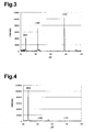
- FIG. 3 is a diagram showing an X-ray diffraction pattern of Example 2 of the thermally conductive sheet.
- FIG. 4 is a diagram showing an X-ray diffraction pattern of Comparative Example 1 of the thermally conductive sheet.
- a thermally conductive sheet according to the present embodiment includes a polymer matrix, and short carbon fibers which are present in the polymer matrix in a state oriented in the direction of thickness of the thermally conductive sheet.
- a ratio I (002) /I (110) between the intensity I (110) of a diffraction peak ascribable to a (110) surface of carbon and the intensity I (002) of a diffraction peak ascribable to a (002) surface of carbon is 10 or less occurring when X-rays are irradiated onto the thermally conductive sheet along the direction of orientation of the short carbon fibers, that is, the direction of the thickness of the thermally conductive sheet.
- the ratio I (002) /I (110) is preferably 1 or less, and more preferably 0.2 or less. Normally, the lower limit value of the ratio I (002) /I (110) is equal to 0.01. In the case of carbon fibers, the (110) surface is orthogonal to the (002) surface corresponding to a base surface, i.e. C surface, and in parallel with the fiber axis. Therefore, the ratio I (002) /I (110) serves as an index indicating the degree of orientation of the short carbon fibers in the thermally conductive sheet.
- the thermally conductive sheet is not particularly limited in hardness, it has preferably a Shore A hardness of 70 or less, and more preferably a Shore A hardness of 40 or less. Particularly preferably, it has an Asker C hardness of 30 or less.
- the thermally conductive sheet has a thickness of 20 ⁇ m or more, and more preferably 100 ⁇ m or more. Further, it is preferred that the thermally conductive sheet has a thickness of 10 mm or less, and more preferably 5 mm or less.
- the thermally conductive sheet has a thermal resistance value of 0.3° C./W or smaller in the direction of thickness thereof.
- the kinds of matrix materials composing the above polymer matrix are not particularly limited.
- Preferred matrix materials include thermoplastic resins, thermoplastic elastomers, curable resins, and crosslinked rubbers.
- the matrix materials may include polymer alloys formed by blending two or more kinds of polymers.
- the polymer matrix may be formed of one kind of matrix material or two or more kinds of matrix materials.
- thermoplastic resins as the matrix materials include polyethylene, polypropylene, ethylene-a-olefin copolymers, such as ethylene-propylene copolymer, polymethylpentene, polyvinyl chloride, polyvinylidene chloride, polyvinyl acetate, ethylene-vinyl acetate copolymer, polyvinyl alcohol, polyacetal, fluororesins, such as polyvinylidene fluoride and polytetrafluoroethylene, polyethylene terephthalate, polybutylene terephthalate, polyethylene naphthalate, polystyrene, polyacrylonitrile, styrene-acrylonitrile copolymer, ABS resin, polyphenylene ether, modified polyphenylene ether, aliphatic polyamides, aromatic polyamides, polyamide imide, polymethacrylic acid, polymethacrylic ester, polyacrylic acid, polyacrylic ester, polycarbonate, polyphen
- thermoplastic elastomers as the matrix materials include styrene-based thermoplastic elastomers, such as styrene-butadiene copolymer, styrene-isoprene block copolymer, and hydrogenated polymer thereof, olefin-based thermoplastic elastomers, vinyl chloride-based thermoplastic elastomers, polyester-based thermoplastic elastomers, polyurethane-based thermoplastic elastomers, and polyamide-based thermoplastic elastomers.
- styrene-based thermoplastic elastomers such as styrene-butadiene copolymer, styrene-isoprene block copolymer, and hydrogenated polymer thereof
- olefin-based thermoplastic elastomers vinyl chloride-based thermoplastic elastomers
- polyester-based thermoplastic elastomers polyester-based thermoplastic elastomers
- curable resins as the matrix materials include epoxy resins, polyimide, bismaleimide resins, benzocyclobutene resins, phenol resins, unsaturated polyesters, diallyl phthalate resins, silicone resins, polyurethane, polyimide silicone, thermally curable polyphenylene ether, and thermally curable modified polyphenylene ether.
- Examples of the crosslinked rubbers as the matrix materials include natural rubber, butadiene rubber, isoprene rubber, nitrile rubber, hydrogenated nitrile rubber, chloroprene rubber, ethylenepropylene rubber, chlorinated polyethylene, chlorosulfonated polyethylene, butyl rubber, halogenated butyl rubber, fluororubber, urethane rubber, and silicone rubber.
- preferable matrix materials are silicone rubber, epoxy resins, polyurethane, unsaturated polyesters, polyimide, bismaleimide resins, benzocyclobutene resins, fluororesins, polyphenylene ether, and thermoplastic elastomers. More preferable matrix materials are silicone rubber, epoxy resins, polyimide, polyurethane, and thermoplastic elastomers.
- the kinds of the short carbon fibers are not particularly limited.
- Preferable short carbon fibers are short graphitized carbon fibers.
- the short graphitized carbon fibers can be produced by carrying out a heat treatment on pitch-based or mesophase pitch-based carbon fibers which can be obtained, e.g. by a melt spinning process, an infusibilizing process, and a graphitizing process, at 2000° C. or higher.
- the short graphitized carbon fibers can also be produced by carrying out a heat treatment on hard organic polymer fibers, such as polyimide fibers, aromatic polyamide fibers, and polybenzoxazole fibers, at 2000° C. or more.
- the short graphitized carbon fibers can also be produced by a vapor phase growth method.
- the short carbon fibers have an average diameter of 5 ⁇ m or more.
- the short carbon fibers have average diameter of 20 ⁇ m or less.
- the short carbon fibers has an average length of 5 ⁇ m or more.
- the short carbon fibers has an average length of 800 ⁇ m or less.
- the short carbon fibers have a thermal conductivity of 200 W/m ⁇ K or more, more preferably 400 W/m ⁇ K or more, and particularly preferably 1000 W/m ⁇ K or more, along the fiber axis.
- the content of the short carbon fibers in the thermally conductive sheet is 5 parts by weight or more relative to 100 parts by weight of the matrix material.
- the content of the short carbon fibers in the thermally conductive sheet is 400 parts by weight or less relative to 100 parts by weight of the matrix material, and more preferably 200 parts by weight or less.
- the short carbon fibers and the matrix material are mixed with each other to prepare a mixture composition.
- the mixture composition is formed into a sheet.
- the formed mixture composition is cured in a state in which the short carbon fibers in the composition are oriented along the direction of thickness of the composition.
- a mixing device such as a blender, a mixer, a roll, or an extruder, may be used when the short carbon fibers and the matrix material are mixed with each other.
- the forming of the mixture composition into a sheet is effected by a variety of methods, such as a bar coater method, a doctor blade method, an extrusion method using a T-die, a calendering method, a pressing method, an injection molding method, a cast molding method, a transfer molding method, or a blow molding method. If the mixture composition is in a liquid form, it may be formed into a sheet by a coating method, a printing method, a dispenser method, or a potting method.
- the short carbon fibers in the formed mixture composition are oriented, for example, by a method using a flow field or a shear field, or by a method utilizing a magnetic field or an electric field.
- the short carbon fibers are oriented by the method utilizing a magnetic field or an electric field.
- the magnetic field or the electric field is applied to the formed but uncured mixture composition, whereby the short carbon fibers in the composition are oriented in parallel with lines of magnetic force or electric force.
- the formed mixture composition may be cured by a thermal curing method, or by other methods than the thermal curing method, such as a light curing method and a moisture curing method.
- a second method of producing the thermally conductive sheet according to the present embodiment will be described.
- a base layer is formed by the matrix material.
- the short carbon fibers are implanted on a surface of the base layer by an electrostatic flocking method.
- the surface of the base layer is covered by the matrix material such that the implanted short carbon fibers are buried.
- the present embodiment has the following advantageous effects:
- the ratio I (002) /I (110) indicates that the short carbon fibers in the thermally conductive sheet are highly oriented along the direction of the thickness of the sheet.
- the short carbon fibers have high thermal conductivity along the fiber axis. Therefore, the thermally conductive sheet in which the short carbon fibers are highly oriented along the direction of the thickness of the sheet has high thermal conductivity along the direction of the thickness thereof. More specifically, if the ratio I (002) /I (110) is 10 or less, the thermally conductive sheet has high thermal conductivity along the direction of the thickness thereof.
- the ratio I (002) /I (110) is 1 or less, the degree of orientation of the short carbon fibers is increased, so that the thermal conductivity of the thermally conductive sheet is further enhanced along the direction of the thickness of the sheet. If the ratio I (002) /I (110) is 0.2 or less, the thermal conductivity of the thermally conductive sheet is still further enhanced along the direction of the thickness of the sheet.
- the hardness of the thermally conductive sheet is equal to or smaller than a Shore A hardness of 70, it is possible to obtain a thermally conductive sheet excellent in stress relaxation property and followability. If the hardness is equal to or smaller than the Shore A hardness of 40, the thermally conductive sheet is improved in stress relaxation property and followability. If the hardness is equal to or smaller than an Asker C hardness of 30, the thermally conductive sheet is further improved in stress relaxation property and followability.
- the thermally conductive sheet has a thickness of 20 ⁇ m or more, it is possible to prevent the thermally conductive sheet from becoming difficult to produce and handle due to too small thickness of the sheet. If the thermally conductive sheet has a thickness of 100 ⁇ m or more, the ease of production and handling of the sheet is increased.
- the thermally conductive sheet has a thickness of 10 mm or less, it is possible to prevent the sheet from becoming lower in thermal conductivity due to too large thickness of the same.
- the thermally conductive sheet in the direction of the thickness thereof is 0.3° C./W or less, the thermally conductive sheet is increased in thermal conductivity in the direction of the thickness thereof.
- the short graphitized carbon fibers have high thermal conductivity. Therefore, if the short carbon fibers contained in the thermally conductive sheet are short graphitized carbon fibers, the thermally conductive sheet is increased in thermal conductivity.
- the average diameter of the short carbon fibers is 5 ⁇ m or more, it becomes easy to orient the short carbon fibers in the mixture composition in a predetermined desired direction.
- Short carbon fibers having an average diameter of 20 ⁇ m or less can be produced at lower manufacturing costs than short carbon fibers having an average diameter larger than 20 ⁇ m. Therefore, if the average diameter of the short carbon fibers is 20 ⁇ m or less, the manufacturing costs of the thermally conductive sheet are reduced.
- Short carbon fibers having an average length of 5 ⁇ m or more can be produced at lower manufacturing costs, and at the same time handled more easily than short carbon fibers having an average length smaller than 5 ⁇ m. Therefore, if the average length of the short carbon fibers is 5 ⁇ m or more, it is possible to reduce the manufacturing costs of the thermally conductive sheet as well as facilitate production of the thermally conductive sheet.
- the average length of the short carbon fibers is 800 ⁇ m or less, it becomes easy to orient the short carbon fibers in the mixture composition in a predetermined desired direction.
- the short carbon fibers have a thermal conductivity of 200 W/m ⁇ K or more along the fiber axis, it is possible to obtain a thermally conductive sheet having high thermal conductivity. If the thermal conductivity of the short carbon fibers is 400 W/m ⁇ K or more, the thermal conductivity of the thermally conductive sheet is further enhanced. If the thermal conductivity of the short carbon fibers is 1000 W/m ⁇ K or more, the thermal conductivity of the thermally conductive sheet is still further enhanced.
- the content of the short carbon fibers in the thermally conductive sheet is 5 parts by weight or more relative to 100 parts by weight of the matrix material, it is possible to prevent the thermally conductive sheet from becoming lower in thermal conductivity due to too small content of the fibers.
- the content of the short carbon fibers in the thermally conductive sheet is 400 parts by weight or less relative to 100 parts by weight of the matrix material, it is possible to prevent the mixture composition from becoming too viscous. This enables the short carbon fibers in the mixture composition to be oriented in a desired direction relatively easily. If the content of the short carbon fibers in the thermally conductive sheet is 200 parts by weight or less relative to 100 parts by weight of the matrix material, it is possible to more positively prevent the mixture composition from becoming too viscous.
- the matrix material is any of thermoplastic resins, thermoplastic elastomers, curable resins, and crosslinked rubber, the mixture composition is excellent in formability.
- the matrix material is any of silicone rubber, epoxy resins, polyurethane, unsaturated polyesters, polyimide, bismaleimide resins, benzocyclobutene resins, fluororesins, polyphenylene ether, and thermoplastic elastomers, it is possible to obtain a thermally conductive sheet excellent in thermal resistance and electric reliability. Further, if the matrix material is any of silicone rubber, epoxy resins, polyimide, polyurethane, and thermoplastic elastomers, the thermally conductive sheet is enhanced in thermal resistance and electric reliability.
- the method utilizing a magnetic field or an electric field is capable of positively and easily orienting the short carbon fibers in the mixture composition in the predetermined direction.
- the short carbon fibers can be positively and easily oriented in the predetermined direction by the electrostatic flocking method as well.
- the present invention is embodied in the thermally conductive sheet, that is, in a thermally conductive formed article in the form of a sheet, this is not limitative, but it may be embodied in a thermally conductive formed article in a form other than the form of a sheet.
- the form of the thermally conductive formed article according to the present invention is not limited to the form of a sheet.
- the present invention may be embodied in a radiator plate, a wiring board, a semiconductor package material, a heat sink, a heat spreader, or a housing.
- the thermally conductive formed article according to the present invention may be a radiator plate, a wiring board, a semiconductor package material, a heat sink, a heat spreader, or a housing.
- the matrix material is any of fluororesins, thermally curable polyphenylene ether, thermally curable modified polyphenylene ether, olefin-based resins, benzocyclobutene resins, polyimide, fluorinated polyimide, polybenzoxazole, and fluorinated polybenzoxazole. This is because the wiring board is required to be small in dielectric constant and dielectric loss tangent, and excellent in high-frequency characteristics.
- the direction of orientation of the short carbon fibers is not necessarily required to coincide with the direction of the thickness of the thermally conductive sheet. It may be changed as required.
- the index indicating the degree of orientation of the short carbon fibers in the thermally conductive sheet not the ratio I (002) /I (110) but a ratio I (002) /I (100) may be used.
- the ratio I (002) /I (100) is obtained based on an intensity I (100) of a diffraction peak ascribable to a (100) surface of carbon and an intensity I (002) of a diffraction peak ascribable to a (002) surface of carbon, occurring when X-rays are irradiated onto the thermally conductive sheet along the direction of orientation of the short carbon fibers.
- the ratio I (002) /I (100) is 10 or less, preferably 1 or less, and more preferably 0.2 or less. Normally, the lower limit value of the ratio I (002) /I (100) is 0.01. Similarly to the (110) surface, the (100) surface is orthogonal to the (002) surface, and in parallel with the fiber axis. Therefore, the ratio I (002) /I (100) as well serves as an index indicating the degree of orientation of the short carbon fibers in the thermally conductive sheet.
- the polymer matrix may be replaced by a metal matrix, a ceramic matrix, or a carbon matrix.
- a matrix material forming the metal matrix include aluminum, copper, and alloys containing them.
- specific examples of a matrix material forming the ceramic matrix include aluminum oxide, aluminum nitride, silicon carbide, silicon nitride, boron nitride, and precursors thereof.
- Specific examples of a matrix material forming the carbon matrix include carbon and graphite.
- the surfaces of the short carbon fibers may be modified in advance.
- the modification of the surfaces of the short carbon fibers is effected, for example, by carrying out oxidation processing, such as electrolytic oxidation, on the surfaces, or by performing processing using a coupling agent or a sizing agent thereon.
- oxidation processing such as electrolytic oxidation
- a coupling agent or a sizing agent thereon.
- each short carbon fiber may be coated with a metal, a ceramic, or an organic polymer in advance.
- a metal, a ceramic, or an organic polymer may be attached in advance to part or a whole of the surface of the short carbon fiber.
- the coating of the short carbon fibers is effected, for example, by electroless plating, electrolytic plating, physical vapor deposition, such as vacuum deposition, sputtering, and ion plating, chemical vapor deposition, a coating method, an immersion method, or a mechanochemical method.
- minute particles are mechanically fixedly attached to the surfaces of the short carbon fibers.
- Short carbon fibers coated with a ferromagnetic material such as nickel or ferrite, are excellently oriented by the magnetic field.
- Short carbon fibers coated with an electrical insulating material such as aluminum oxide, magnesium oxide, boron nitride, aluminum nitride, silicon nitride, silicon carbide, aluminum hydroxide, or an organic polymer, are excellently oriented by the electric field, and can be suitably employed in the electrostatic flocking method.
- the thermally conductive sheet according to the above embodiment may contain two or more kinds of short carbon fibers.
- the thermally conductive sheet may contain short graphitized carbon fibers and short non-graphitized carbon fibers.
- the thermally conductive sheet may contain two or more kinds of short graphitized carbon fibers, or two or more kinds of short non-graphitized carbon fibers.
- the thermally conductive sheet according to the above embodiment may contain a metal, a ceramic, or a carbon in a form other than the form of short carbon fibers, as components other than the short carbon fibers and the matrix material.
- the metal include silver, copper, and gold.
- the ceramic include aluminum oxide, magnesium oxide, boron nitride, aluminum nitride, silicon nitride, silicon carbide, and aluminum hydroxide.
- the form of carbon than the short carbon fibers include forms of non-fibers, such as balls, beads, whiskers, scales, flat plates, coils, monolayer tubes, and multilayer tubes, and a form of mesocarbon microbeads.
- the above non-fiber forms of carbon may be either of graphitized carbon and non-graphitized carbon.
- Specific examples of the form of carbon other than the short carbon fibers further include graphitized carbon in the form of non-fibers, produced by carrying out a heat treatment on organic polymers, such as polyimide, polyamide, and polybenzoxazole, at 2400° C. or more.
- Monolayer carbonnanotubes have high thermal conductivity, so that if the monolayer carbonnanotubes are added, the thermally conductive sheet is improved in thermal conductivity.
- the thermal conductivity of the thermally conductive sheet is further enhanced. If the ceramic is added, the thermally conductive sheet is improved in electrical insulating property. Therefore, the thermally conductive sheet having the ceramic added thereto can be suitably employed for uses demanding electrical insulating property.
- the thermally conductive sheet according to the above embodiment may contain a thermally conductive filler, such as a resin coated with metal, a volatile organic solvent, and a reactive plasticizer, as components other than the short carbon fibers and the matrix material.
- a thermally conductive filler such as a resin coated with metal, a volatile organic solvent, and a reactive plasticizer, as components other than the short carbon fibers and the matrix material.
- a mixture composition A 100 parts by weight of an addition-type liquid silicone rubber (TSE 3070 produced by GE Toshiba Silicones), and 110 parts by weight of pitch-based short carbon fibers (Melblon Milled Fiber produced by Petoca Materials Limited) were mixed to prepare a mixture composition A.
- the pitch-based short carbon fibers have an average length of 100 ⁇ m, an average diameter of 9 ⁇ m, and a thermal conductivity of 1000 W/m ⁇ K along the fiber axis.
- the prepared mixture composition A was formed into a sheet after carrying out pressure reduction and deaeration.
- a magnetic field having a magnetic flux density of 10 teslas was applied to the formed mixture composition A by using a superconducting magnet, whereby the short carbon fibers in the mixture composition A were sufficiently oriented along the direction of thickness of the mixture composition A.
- the formed mixture composition A was heated to be cured, whereby a thermally conductive sheet which was 20 mm long by 20 mm wide by 1 mm thick was obtained.
- the above mixture composition A was formed into a sheet after carrying out pressure reduction and deaeration. Then, a magnetic field having a magnetic flux density of 6 teslas was applied to the formed mixture composition A by using the superconducting magnet, whereby the short carbon fibers in the mixture composition A were sufficiently oriented along the direction of thickness of the mixture composition A. After that, the formed mixture composition A was heated to be cured, whereby a thermally conductive sheet which was 20 mm long by 20 mm wide by 1 mm thick was obtained.
- the above mixture composition A was formed into a sheet after carrying out pressure reduction and deaeration. Next, the formed mixture composition A was heated to be cured, whereby a thermally conductive sheet which was 20 mm long by 20 mm wide by 1 mm thick was obtained.
- the above mixture composition A was formed into a sheet after carrying out pressure reduction and deaeration. Then, a magnetic field having a magnetic flux density of 2 teslas was applied to the formed mixture composition A by using the superconducting magnet, whereby some of the short carbon fibers in the mixture composition A were oriented along the direction of thickness of the mixture composition A. After that, the formed mixture composition A was heated to be cured, whereby a thermally conductive sheet which was 20 mm long by 20 mm wide by 1 mm thick was obtained.
- a liquid epoxy resin produced by Three Bond Company, Ltd
- 40 parts by weight of pitch-based short carbon fibers K1100X produced by Amoco Fabric and Fibers Company
- 10 parts by weight of a boron nitride powder UHP-EX produced by Showa Denko KK
- the pitch-based short carbon fibers have an average length of 100 ⁇ m, an average diameter of 10 ⁇ m, and a thermal conductivity of 1050 W/m ⁇ K along the fiber axis.
- the prepared mixture composition B was formed into a sheet after carrying out pressure reduction and deaeration.
- a magnetic field having a magnetic flux density of 10 teslas was applied to the formed mixture composition B by using the superconducting magnet, whereby the short carbon fibers in the mixture composition B were sufficiently oriented along the direction of thickness of the mixture composition B.
- the formed mixture composition B was heated to be cured, whereby a thermally conductive sheet which was 20 mm long by 20 mm wide by 1 mm thick was obtained.
- the above mixture composition B was formed into a sheet after carrying out pressure reduction and deaeration. Then, a magnetic field having a magnetic flux density of 1 tesla was applied to the formed mixture composition B by using the superconducting magnet, whereby some of the short carbon fibers in the mixture composition B were oriented along the direction of thickness of the mixture composition B. After that, the formed mixture composition B was heated to be cured, whereby a thermally conductive sheet which was 20 mm long by 20 mm wide by 1 mm thick was obtained.
- a polyimide varnish (UPIFINE ST produced by UBE INDUSTRIES, LTD., solid content density of 18.5%) containing N-methyl pyrrolidone, 40 parts by weight of short carbon fibers (produced by Nippon Graphite Fiber), and 40 parts by weight of a spherical aluminum oxide powder (A20 produced by Showa Denko KK, average particle diameter of 30 ⁇ m) were mixed to prepare a mixture composition C.
- the short carbon fibers have a surface coated with ferromagnetic nickel by electroless plating, and have an average length of 25 ⁇ m, an average diameter of 10 ⁇ m, and a thermal conductivity of 1000 W/m ⁇ K along the fiber axis.
- the prepared mixture composition C was formed into a block which was 20 mm long by 20 mm wide by 40 mm thick. Then, a magnetic field having a magnetic flux density of 0.5 teslas was applied to the formed mixture composition C by using a permanent magnet, whereby the short carbon fibers in the mixture composition C were sufficiently oriented along the direction of thickness of the mixture composition C. Then, the N-methyl pyrrolidone was removed, and further the formed mixture composition C was heated to be cured, whereby a thermally conductive formed article in the form of a block was obtained. After that, the thermally conductive formed article was sliced to obtain a thermally conductive sheet which was 20 mm long by 20 mm wide by 200 ⁇ m thick and in which the short carbon fibers were oriented along the direction of thickness thereof.
- the above mixture composition C was formed into a block which was 20 mm long ⁇ 20 mm wide ⁇ 40 mm thick. Then, a magnetic field having a magnetic flux density of 0.1 tesla was applied to the formed mixture composition C by using a permanent magnet, whereby some of the short carbon fibers in the mixture composition C were oriented along the direction of thickness of the mixture composition C. Then, the N-methyl pyrrolidone was removed, and further the formed mixture composition C was heated to be cured, whereby a thermally conductive formed article in the form of a block was obtained. Subsequently, the thermally conductive formed article was sliced to obtain a thermally conductive sheet which was 20 mm long by 20 mm wide by 200 ⁇ m thick and in which some of the short carbon fibers were oriented along the direction of thickness thereof.
- An addition-type liquid silicone rubber (TSE 3070 produced by GE Toshiba Silicones) was printed on a mold releasing film by screen printing to form a base layer having a thickness of 60 ⁇ m. Then, pitch-based short carbon fibers (K1100X produced by Amoco Fabric and Fibers Company) were implanted on a surface of the base layer by the electrostatic flocking method. Subsequently, the surface of the base layer was covered with the addition-type liquid silicone rubber (the same as the above) such that the implanted short carbon fibers were buried. Then, the liquid silicone rubber was heated to be cured, whereby a thermally conductive sheet having a thickness of 500 ⁇ m was obtained.
- TSE 3070 produced by GE Toshiba Silicones
- the pitch-based short carbon fibers have an average fiber length of 150 ⁇ m, an average diameter of 10 ⁇ m, and a thermal conductivity of 1050 W/m ⁇ K along the fiber axis.
- the content of the short carbon fibers in the thermally conductive sheet is 8 parts by weight relative to 100 parts by weight of the silicone rubber.
- An addition-type liquid silicone rubber (TSE 3070 produced by GE Toshiba Silicones) was printed on a mold releasing film by screen printing to form a base layer having a thickness of 60 ⁇ m. Then, a mixture of 100 parts by weight of the addition-type liquid silicone rubber (the same as the above), and 8 parts by weight of a PAN-based short carbon fibers (K1352U produced by Mitsubishi Chemical Co.) was laminated on the base layer. After that, the laminated material was heated to be cured, whereby a thermally conductive sheet having a thickness of 500 ⁇ m was obtained.
- the short carbon fibers have an average fiber length of 150 ⁇ m, an average diameter of 10 ⁇ m, and a thermal conductivity of 140 W/m ⁇ K along the fiber axis.
- FIG. 1 shows a correlation between the thermal resistance and the ratio I (002) /I (110) found in the thermally conductive sheet of Examples 1 to 5 and Comparative Examples 1 to 5.
- numerals each in a circle represent the respective numbers of Examples
- numerals each in a triangle represent the respective numbers of Comparative Example.
- FIGS. 2 to 4 each show an X-ray diffraction pattern which was obtained by irradiating X-rays along the direction of thickness of the thermally conductive sheet obtained in Examples 1 and 2 and Comparative Example 3.
- the thermal resistance was calculated based on the temperature of a TO-3 transistor and the temperature of a copper plate, which were measured when a thermally conductive sheet held between the transistor and the copper plate was heated by the transistor at 30 W. The calculation was performed by using the following equation:
- the ratios I (002) /I (110) , and the ratios I (002) /I (100) were calculated based on the intensity I (110) of a diffraction peak ascribable to the (110) surface of carbon, the intensity I (100) of a diffraction peak ascribable to the (100) surface of carbon, and the intensity I (002) of a diffraction peak ascribable to the (002) surface of carbon, occurring when X-rays were irradiated onto each thermally conductive sheet along the direction of the thickness of the thermally conductive sheet.
- an X-ray diffraction apparatus (MXP-18 produced by Mac Science Co.
Landscapes
- Chemical & Material Sciences (AREA)
- Engineering & Computer Science (AREA)
- Organic Chemistry (AREA)
- Chemical Kinetics & Catalysis (AREA)
- Ceramic Engineering (AREA)
- Materials Engineering (AREA)
- Composite Materials (AREA)
- Polymers & Plastics (AREA)
- Manufacturing & Machinery (AREA)
- Medicinal Chemistry (AREA)
- Health & Medical Sciences (AREA)
- Structural Engineering (AREA)
- Textile Engineering (AREA)
- Mechanical Engineering (AREA)
- Compositions Of Macromolecular Compounds (AREA)
- Reinforced Plastic Materials (AREA)
- Inorganic Fibers (AREA)
- Chemical Or Physical Treatment Of Fibers (AREA)
- Ceramic Products (AREA)
- Manufacture Of Alloys Or Alloy Compounds (AREA)
- Cooling Or The Like Of Electrical Apparatus (AREA)
- Manufacture Of Macromolecular Shaped Articles (AREA)
Abstract
Description
- The present invention relates to a thermally conductive formed article and a method of manufacturing the same.
- Conventionally, as a thermally conductive formed article, Japanese Laid-open Patent Publication No. 5-222620 discloses a formed article in which pitch-based short carbon fibers having a specific cross-sectional structure are dispersed in a matrix. Japanese Laid-open Patent Publication No. 9-283955 discloses a formed article in which short graphitized carbon fibers having a specific aspect ratio are dispersed in a matrix. Japanese Laid-open Patent Publication No. 4-173235, Japanese Laid-open Patent Publication No. 10-330502, Japanese Laid-open Patent Publication No. 11-46021, Japanese Laid-open Patent Publication No. 11-302545, Japanese Laid-open Patent Publication No. 2000-195998, Japanese Laid-open Patent Publication No. 2000-281802, Japanese Laid-open Patent Publication No. 2001-139833, and Japanese Laid-open Patent Publication No. 2001-353736 disclose formed articles in which short carbon fibers are oriented in a fixed direction in a polymer matrix. Japanese Laid-open Patent Publication No. 11-97593, and Japanese Laid-open Patent Publication No. 11-199949 disclose formed articles in which short carbon fibers are oriented in a fixed direction in a metal matrix.
- The above conventional thermally conductive formed articles are used, for instance, in electronic devices and apparatuses as heat-conducting members for conducting heat generated from electronic components out of the apparatus so as to prevent overheat of the electronic components. In electronic devices and apparatuses, with enhancement of performance thereof, the electronic components thereof generate an increasing amount of heat. Therefore, recently, thermally conductive formed articles used as heat-conducting members have a requirement of having high thermal conductivity. However, the conventional thermally conductive formed articles do not always have thermal conductivity high enough to meet the requirement.
- It is an object of the present invention to provide a thermally conductive formed article having high thermal conductivity and a method of manufacturing the thermally conductive formed article.
- To achieve the above objective, the present invention provides a thermally conductive formed article. The formed article includes a matrix, and short carbon fibers which are present in the matrix in a state oriented in a fixed direction. A ratio I (002)/I(110) between an intensity I(110) of a diffraction peak ascribable to a (110) surface of carbon and an intensity I(002) of a diffraction peak ascribable to a (002) surface of carbon, occurring when X-rays are irradiated onto the thermally conductive formed article along the direction of orientation of the short carbon fibers, is 10 or less.
- The wording “X-rays are irradiated along the direction of orientation of the short carbon fibers” is intended to mean that X-rays are irradiated along a direction in which the short carbon fibers are substantially oriented, that is, a direction in which most of the short carbon fibers are oriented.
- The present invention also provides a thermally conductive formed article. The formed article includes a matrix, and short carbon fibers which are present in the matrix in a state oriented in a fixed direction. A ratio I (002)/I(100) between an intensity I(100) of a diffraction peak ascribable to a (100) surface of carbon and an intensity I(002) of a diffraction peak ascribable to a (002) surface of carbon, occurring when X-rays are irradiated onto the thermally conductive formed article along the direction of orientation of the short carbon fibers, is 10 or less.
- The present invention further provides a method of manufacturing a thermally conductive formed article. The method includes the steps of forming a mixture composition prepared by mixing a matrix material and short carbon fibers with each other into a predetermine form to produce a formed but uncured mixture composition; applying an electric field or a magnetic field to the formed but uncured mixture composition to thereby orient the short carbon fibers in the mixture composition in a fixed direction such that a ratio I (002)/I(110) between an intensity I(110) of a diffraction peak ascribable to a (110) surface of carbon and an intensity I(002) of a diffraction peak ascribable to a (002) surface of carbon, occurring when X-rays are irradiated onto the thermally conductive formed article along a direction of orientation of the short carbon fibers, is 10 or less; and curing the formed but uncured mixture composition.
- The present invention still further provides a method of manufacturing a thermally conductive formed article. The method includes the steps of forming a base layer by a matrix material; implanting short carbon fibers on a surface of the base layer by an electrostatic flocking method such that a ratio I (002)/I(110) between an intensity I(110) of a diffraction peak ascribable to a (110) surface of carbon and an intensity I(002) of a diffraction peak ascribable to a (002) surface of carbon, occurring when X-rays are irradiated onto the thermally conductive formed article along a direction of orientation of the short carbon fibers, is 10 or less; and covering the surface of the base layer by the matrix material such that the implanted short carbon fibers are buried.
- Other aspects and advantages of the invention will become apparent from the following description, taken in conjunction with the accompanying drawings, illustrating by way of example the principles of the invention.
- The invention, together with objects and advantages thereof, may best be understood by reference to the following description of the presently preferred embodiments together with the accompanying drawings in which:
- FIG. 1 shows a graph illustrating a correlation between a thermal resistance and a ratio I (002)/I(110) found in the thermally conductive sheet of Examples 1 to 5 and Comparative Examples 1 to 5;
- FIG. 2 is a diagram showing an X-ray diffraction pattern of Example 1 of the thermally conductive sheet;
- FIG. 3 is a diagram showing an X-ray diffraction pattern of Example 2 of the thermally conductive sheet; and
- FIG. 4 is a diagram showing an X-ray diffraction pattern of Comparative Example 1 of the thermally conductive sheet.
- The present invention will now be described in detail with reference to the drawings showing a preferred embodiment thereof.
- A thermally conductive sheet according to the present embodiment includes a polymer matrix, and short carbon fibers which are present in the polymer matrix in a state oriented in the direction of thickness of the thermally conductive sheet. A ratio I (002)/I(110) between the intensity I(110) of a diffraction peak ascribable to a (110) surface of carbon and the intensity I(002) of a diffraction peak ascribable to a (002) surface of carbon is 10 or less occurring when X-rays are irradiated onto the thermally conductive sheet along the direction of orientation of the short carbon fibers, that is, the direction of the thickness of the thermally conductive sheet. The ratio I(002)/I(110) is preferably 1 or less, and more preferably 0.2 or less. Normally, the lower limit value of the ratio I(002)/I(110) is equal to 0.01. In the case of carbon fibers, the (110) surface is orthogonal to the (002) surface corresponding to a base surface, i.e. C surface, and in parallel with the fiber axis. Therefore, the ratio I(002)/I(110) serves as an index indicating the degree of orientation of the short carbon fibers in the thermally conductive sheet.
- Although the thermally conductive sheet is not particularly limited in hardness, it has preferably a Shore A hardness of 70 or less, and more preferably a Shore A hardness of 40 or less. Particularly preferably, it has an Asker C hardness of 30 or less.
- It is preferred that the thermally conductive sheet has a thickness of 20 μm or more, and more preferably 100 μm or more. Further, it is preferred that the thermally conductive sheet has a thickness of 10 mm or less, and more preferably 5 mm or less.
- It is preferred that the thermally conductive sheet has a thermal resistance value of 0.3° C./W or smaller in the direction of thickness thereof.
- The kinds of matrix materials composing the above polymer matrix are not particularly limited. Preferred matrix materials include thermoplastic resins, thermoplastic elastomers, curable resins, and crosslinked rubbers. The matrix materials may include polymer alloys formed by blending two or more kinds of polymers. The polymer matrix may be formed of one kind of matrix material or two or more kinds of matrix materials.
- Examples of the thermoplastic resins as the matrix materials include polyethylene, polypropylene, ethylene-a-olefin copolymers, such as ethylene-propylene copolymer, polymethylpentene, polyvinyl chloride, polyvinylidene chloride, polyvinyl acetate, ethylene-vinyl acetate copolymer, polyvinyl alcohol, polyacetal, fluororesins, such as polyvinylidene fluoride and polytetrafluoroethylene, polyethylene terephthalate, polybutylene terephthalate, polyethylene naphthalate, polystyrene, polyacrylonitrile, styrene-acrylonitrile copolymer, ABS resin, polyphenylene ether, modified polyphenylene ether, aliphatic polyamides, aromatic polyamides, polyamide imide, polymethacrylic acid, polymethacrylic ester, polyacrylic acid, polyacrylic ester, polycarbonate, polyphenylene sulfide, polysulfone, polyether sulfone, polyether nitrile, polyether ketone, polyketone, liquid crystal polymers, silicone resins, and ionomers.
- Examples of the thermoplastic elastomers as the matrix materials include styrene-based thermoplastic elastomers, such as styrene-butadiene copolymer, styrene-isoprene block copolymer, and hydrogenated polymer thereof, olefin-based thermoplastic elastomers, vinyl chloride-based thermoplastic elastomers, polyester-based thermoplastic elastomers, polyurethane-based thermoplastic elastomers, and polyamide-based thermoplastic elastomers.
- Examples of the curable resins as the matrix materials include epoxy resins, polyimide, bismaleimide resins, benzocyclobutene resins, phenol resins, unsaturated polyesters, diallyl phthalate resins, silicone resins, polyurethane, polyimide silicone, thermally curable polyphenylene ether, and thermally curable modified polyphenylene ether.
- Examples of the crosslinked rubbers as the matrix materials include natural rubber, butadiene rubber, isoprene rubber, nitrile rubber, hydrogenated nitrile rubber, chloroprene rubber, ethylenepropylene rubber, chlorinated polyethylene, chlorosulfonated polyethylene, butyl rubber, halogenated butyl rubber, fluororubber, urethane rubber, and silicone rubber.
- Of the above matrix materials, preferable matrix materials are silicone rubber, epoxy resins, polyurethane, unsaturated polyesters, polyimide, bismaleimide resins, benzocyclobutene resins, fluororesins, polyphenylene ether, and thermoplastic elastomers. More preferable matrix materials are silicone rubber, epoxy resins, polyimide, polyurethane, and thermoplastic elastomers.
- The kinds of the short carbon fibers are not particularly limited. Preferable short carbon fibers are short graphitized carbon fibers. The short graphitized carbon fibers can be produced by carrying out a heat treatment on pitch-based or mesophase pitch-based carbon fibers which can be obtained, e.g. by a melt spinning process, an infusibilizing process, and a graphitizing process, at 2000° C. or higher. The short graphitized carbon fibers can also be produced by carrying out a heat treatment on hard organic polymer fibers, such as polyimide fibers, aromatic polyamide fibers, and polybenzoxazole fibers, at 2000° C. or more. Further, the short graphitized carbon fibers can also be produced by a vapor phase growth method.
- Preferably, the short carbon fibers have an average diameter of 5 μm or more. Preferably, the short carbon fibers have average diameter of 20 μm or less.
- Preferably, the short carbon fibers has an average length of 5 μm or more. Preferably, the short carbon fibers has an average length of 800 μm or less.
- Preferably, the short carbon fibers have a thermal conductivity of 200 W/m·K or more, more preferably 400 W/m·K or more, and particularly preferably 1000 W/m·K or more, along the fiber axis.
- Preferably, the content of the short carbon fibers in the thermally conductive sheet is 5 parts by weight or more relative to 100 parts by weight of the matrix material. Preferably, the content of the short carbon fibers in the thermally conductive sheet is 400 parts by weight or less relative to 100 parts by weight of the matrix material, and more preferably 200 parts by weight or less.
- Next, a first method of producing the thermally conductive sheet according to the present embodiment will be described. In this method, first, the short carbon fibers and the matrix material are mixed with each other to prepare a mixture composition. Subsequently, the mixture composition is formed into a sheet. The formed mixture composition is cured in a state in which the short carbon fibers in the composition are oriented along the direction of thickness of the composition.
- A mixing device, such as a blender, a mixer, a roll, or an extruder, may be used when the short carbon fibers and the matrix material are mixed with each other.
- The forming of the mixture composition into a sheet is effected by a variety of methods, such as a bar coater method, a doctor blade method, an extrusion method using a T-die, a calendering method, a pressing method, an injection molding method, a cast molding method, a transfer molding method, or a blow molding method. If the mixture composition is in a liquid form, it may be formed into a sheet by a coating method, a printing method, a dispenser method, or a potting method.
- The short carbon fibers in the formed mixture composition are oriented, for example, by a method using a flow field or a shear field, or by a method utilizing a magnetic field or an electric field. Preferably, the short carbon fibers are oriented by the method utilizing a magnetic field or an electric field. When the method utilizing a magnetic field or an electric field is employed, the magnetic field or the electric field is applied to the formed but uncured mixture composition, whereby the short carbon fibers in the composition are oriented in parallel with lines of magnetic force or electric force.
- If the matrix material is a curable resin or a crosslinked rubber, the formed mixture composition may be cured by a thermal curing method, or by other methods than the thermal curing method, such as a light curing method and a moisture curing method.
- Next, a second method of producing the thermally conductive sheet according to the present embodiment will be described. In this method, first, a base layer is formed by the matrix material. Then, the short carbon fibers are implanted on a surface of the base layer by an electrostatic flocking method. After that, the surface of the base layer is covered by the matrix material such that the implanted short carbon fibers are buried.
- The present embodiment has the following advantageous effects:
- For the ratio I (002)/I(110) to have a value equal to or smaller than 10 indicates that the short carbon fibers in the thermally conductive sheet are highly oriented along the direction of the thickness of the sheet. The short carbon fibers have high thermal conductivity along the fiber axis. Therefore, the thermally conductive sheet in which the short carbon fibers are highly oriented along the direction of the thickness of the sheet has high thermal conductivity along the direction of the thickness thereof. More specifically, if the ratio I(002)/I(110) is 10 or less, the thermally conductive sheet has high thermal conductivity along the direction of the thickness thereof. If the ratio I(002)/I(110) is 1 or less, the degree of orientation of the short carbon fibers is increased, so that the thermal conductivity of the thermally conductive sheet is further enhanced along the direction of the thickness of the sheet. If the ratio I(002)/I(110) is 0.2 or less, the thermal conductivity of the thermally conductive sheet is still further enhanced along the direction of the thickness of the sheet.
- If the hardness of the thermally conductive sheet is equal to or smaller than a Shore A hardness of 70, it is possible to obtain a thermally conductive sheet excellent in stress relaxation property and followability. If the hardness is equal to or smaller than the Shore A hardness of 40, the thermally conductive sheet is improved in stress relaxation property and followability. If the hardness is equal to or smaller than an Asker C hardness of 30, the thermally conductive sheet is further improved in stress relaxation property and followability.
- If the thermally conductive sheet has a thickness of 20 μm or more, it is possible to prevent the thermally conductive sheet from becoming difficult to produce and handle due to too small thickness of the sheet. If the thermally conductive sheet has a thickness of 100 μm or more, the ease of production and handling of the sheet is increased.
- If the thermally conductive sheet has a thickness of 10 mm or less, it is possible to prevent the sheet from becoming lower in thermal conductivity due to too large thickness of the same.
- If the value of thermal resistance of the thermally conductive sheet in the direction of the thickness thereof is 0.3° C./W or less, the thermally conductive sheet is increased in thermal conductivity in the direction of the thickness thereof.
- The short graphitized carbon fibers have high thermal conductivity. Therefore, if the short carbon fibers contained in the thermally conductive sheet are short graphitized carbon fibers, the thermally conductive sheet is increased in thermal conductivity.
- If the average diameter of the short carbon fibers is 5 μm or more, it becomes easy to orient the short carbon fibers in the mixture composition in a predetermined desired direction.
- Short carbon fibers having an average diameter of 20 μm or less can be produced at lower manufacturing costs than short carbon fibers having an average diameter larger than 20 μm. Therefore, if the average diameter of the short carbon fibers is 20 μm or less, the manufacturing costs of the thermally conductive sheet are reduced.
- Short carbon fibers having an average length of 5 μm or more can be produced at lower manufacturing costs, and at the same time handled more easily than short carbon fibers having an average length smaller than 5 μm. Therefore, if the average length of the short carbon fibers is 5 μm or more, it is possible to reduce the manufacturing costs of the thermally conductive sheet as well as facilitate production of the thermally conductive sheet.
- If the average length of the short carbon fibers is 800 μm or less, it becomes easy to orient the short carbon fibers in the mixture composition in a predetermined desired direction.
- If the short carbon fibers have a thermal conductivity of 200 W/m·K or more along the fiber axis, it is possible to obtain a thermally conductive sheet having high thermal conductivity. If the thermal conductivity of the short carbon fibers is 400 W/m·K or more, the thermal conductivity of the thermally conductive sheet is further enhanced. If the thermal conductivity of the short carbon fibers is 1000 W/m·K or more, the thermal conductivity of the thermally conductive sheet is still further enhanced.
- If the content of the short carbon fibers in the thermally conductive sheet is 5 parts by weight or more relative to 100 parts by weight of the matrix material, it is possible to prevent the thermally conductive sheet from becoming lower in thermal conductivity due to too small content of the fibers.
- If the content of the short carbon fibers in the thermally conductive sheet is 400 parts by weight or less relative to 100 parts by weight of the matrix material, it is possible to prevent the mixture composition from becoming too viscous. This enables the short carbon fibers in the mixture composition to be oriented in a desired direction relatively easily. If the content of the short carbon fibers in the thermally conductive sheet is 200 parts by weight or less relative to 100 parts by weight of the matrix material, it is possible to more positively prevent the mixture composition from becoming too viscous.
- If the matrix material is any of thermoplastic resins, thermoplastic elastomers, curable resins, and crosslinked rubber, the mixture composition is excellent in formability.
- If the matrix material is any of silicone rubber, epoxy resins, polyurethane, unsaturated polyesters, polyimide, bismaleimide resins, benzocyclobutene resins, fluororesins, polyphenylene ether, and thermoplastic elastomers, it is possible to obtain a thermally conductive sheet excellent in thermal resistance and electric reliability. Further, if the matrix material is any of silicone rubber, epoxy resins, polyimide, polyurethane, and thermoplastic elastomers, the thermally conductive sheet is enhanced in thermal resistance and electric reliability.
- The method utilizing a magnetic field or an electric field is capable of positively and easily orienting the short carbon fibers in the mixture composition in the predetermined direction. The short carbon fibers can be positively and easily oriented in the predetermined direction by the electrostatic flocking method as well.
- The above embodiment may be modified as follows:
- Although in the above embodiment, the present invention is embodied in the thermally conductive sheet, that is, in a thermally conductive formed article in the form of a sheet, this is not limitative, but it may be embodied in a thermally conductive formed article in a form other than the form of a sheet. In short, the form of the thermally conductive formed article according to the present invention is not limited to the form of a sheet.
- The present invention may be embodied in a radiator plate, a wiring board, a semiconductor package material, a heat sink, a heat spreader, or a housing. In other words, the thermally conductive formed article according to the present invention may be a radiator plate, a wiring board, a semiconductor package material, a heat sink, a heat spreader, or a housing. When the present invention is embodied in a wiring board, it is preferred that the matrix material is any of fluororesins, thermally curable polyphenylene ether, thermally curable modified polyphenylene ether, olefin-based resins, benzocyclobutene resins, polyimide, fluorinated polyimide, polybenzoxazole, and fluorinated polybenzoxazole. This is because the wiring board is required to be small in dielectric constant and dielectric loss tangent, and excellent in high-frequency characteristics.
- The direction of orientation of the short carbon fibers is not necessarily required to coincide with the direction of the thickness of the thermally conductive sheet. It may be changed as required.
- As the index indicating the degree of orientation of the short carbon fibers in the thermally conductive sheet, not the ratio I (002)/I(110) but a ratio I(002)/I(100) may be used. The ratio I(002)/I(100) is obtained based on an intensity I(100) of a diffraction peak ascribable to a (100) surface of carbon and an intensity I(002) of a diffraction peak ascribable to a (002) surface of carbon, occurring when X-rays are irradiated onto the thermally conductive sheet along the direction of orientation of the short carbon fibers. The ratio I(002)/I(100) is 10 or less, preferably 1 or less, and more preferably 0.2 or less. Normally, the lower limit value of the ratio I(002)/I(100) is 0.01. Similarly to the (110) surface, the (100) surface is orthogonal to the (002) surface, and in parallel with the fiber axis. Therefore, the ratio I(002)/I(100) as well serves as an index indicating the degree of orientation of the short carbon fibers in the thermally conductive sheet.
- The polymer matrix may be replaced by a metal matrix, a ceramic matrix, or a carbon matrix. Examples of a matrix material forming the metal matrix include aluminum, copper, and alloys containing them. Further, specific examples of a matrix material forming the ceramic matrix include aluminum oxide, aluminum nitride, silicon carbide, silicon nitride, boron nitride, and precursors thereof. Specific examples of a matrix material forming the carbon matrix include carbon and graphite.
- The surfaces of the short carbon fibers may be modified in advance. The modification of the surfaces of the short carbon fibers is effected, for example, by carrying out oxidation processing, such as electrolytic oxidation, on the surfaces, or by performing processing using a coupling agent or a sizing agent thereon. By modifying the surfaces of the short carbon fibers, wettability and peel strength between the matrix material and the short carbon fibers as well as a filling property of the short carbon fibers are enhanced.
- Part or a whole of the surface of each short carbon fiber may be coated with a metal, a ceramic, or an organic polymer in advance. In other words, a metal, a ceramic, or an organic polymer may be attached in advance to part or a whole of the surface of the short carbon fiber. The coating of the short carbon fibers is effected, for example, by electroless plating, electrolytic plating, physical vapor deposition, such as vacuum deposition, sputtering, and ion plating, chemical vapor deposition, a coating method, an immersion method, or a mechanochemical method. In the mechanochemical method, minute particles are mechanically fixedly attached to the surfaces of the short carbon fibers. Short carbon fibers coated with a ferromagnetic material, such as nickel or ferrite, are excellently oriented by the magnetic field. Short carbon fibers coated with an electrical insulating material, such as aluminum oxide, magnesium oxide, boron nitride, aluminum nitride, silicon nitride, silicon carbide, aluminum hydroxide, or an organic polymer, are excellently oriented by the electric field, and can be suitably employed in the electrostatic flocking method.
- The thermally conductive sheet according to the above embodiment may contain two or more kinds of short carbon fibers. For instance, the thermally conductive sheet may contain short graphitized carbon fibers and short non-graphitized carbon fibers. Further, the thermally conductive sheet may contain two or more kinds of short graphitized carbon fibers, or two or more kinds of short non-graphitized carbon fibers.
- The thermally conductive sheet according to the above embodiment may contain a metal, a ceramic, or a carbon in a form other than the form of short carbon fibers, as components other than the short carbon fibers and the matrix material. Examples of the metal include silver, copper, and gold. Examples of the ceramic include aluminum oxide, magnesium oxide, boron nitride, aluminum nitride, silicon nitride, silicon carbide, and aluminum hydroxide. Examples of the form of carbon than the short carbon fibers include forms of non-fibers, such as balls, beads, whiskers, scales, flat plates, coils, monolayer tubes, and multilayer tubes, and a form of mesocarbon microbeads. The above non-fiber forms of carbon may be either of graphitized carbon and non-graphitized carbon. Specific examples of the form of carbon other than the short carbon fibers further include graphitized carbon in the form of non-fibers, produced by carrying out a heat treatment on organic polymers, such as polyimide, polyamide, and polybenzoxazole, at 2400° C. or more. Monolayer carbonnanotubes have high thermal conductivity, so that if the monolayer carbonnanotubes are added, the thermally conductive sheet is improved in thermal conductivity. Especially, if the monolayer carbonnanotubes are oriented similarly to the short carbon fibers, the thermal conductivity of the thermally conductive sheet is further enhanced. If the ceramic is added, the thermally conductive sheet is improved in electrical insulating property. Therefore, the thermally conductive sheet having the ceramic added thereto can be suitably employed for uses demanding electrical insulating property.
- The thermally conductive sheet according to the above embodiment may contain a thermally conductive filler, such as a resin coated with metal, a volatile organic solvent, and a reactive plasticizer, as components other than the short carbon fibers and the matrix material. When the organic solvent and the plasticizer are added, the viscosity of the mixture composition is lowered.
- Next, the present invention will be described in more detail with reference to Examples and Comparative Examples.
- 100 parts by weight of an addition-type liquid silicone rubber (TSE 3070 produced by GE Toshiba Silicones), and 110 parts by weight of pitch-based short carbon fibers (Melblon Milled Fiber produced by Petoca Materials Limited) were mixed to prepare a mixture composition A. The pitch-based short carbon fibers have an average length of 100 μm, an average diameter of 9 μm, and a thermal conductivity of 1000 W/m·K along the fiber axis. The prepared mixture composition A was formed into a sheet after carrying out pressure reduction and deaeration. Then, a magnetic field having a magnetic flux density of 10 teslas was applied to the formed mixture composition A by using a superconducting magnet, whereby the short carbon fibers in the mixture composition A were sufficiently oriented along the direction of thickness of the mixture composition A. After that, the formed mixture composition A was heated to be cured, whereby a thermally conductive sheet which was 20 mm long by 20 mm wide by 1 mm thick was obtained.
- The above mixture composition A was formed into a sheet after carrying out pressure reduction and deaeration. Then, a magnetic field having a magnetic flux density of 6 teslas was applied to the formed mixture composition A by using the superconducting magnet, whereby the short carbon fibers in the mixture composition A were sufficiently oriented along the direction of thickness of the mixture composition A. After that, the formed mixture composition A was heated to be cured, whereby a thermally conductive sheet which was 20 mm long by 20 mm wide by 1 mm thick was obtained.
- The above mixture composition A was formed into a sheet after carrying out pressure reduction and deaeration. Next, the formed mixture composition A was heated to be cured, whereby a thermally conductive sheet which was 20 mm long by 20 mm wide by 1 mm thick was obtained.
- The above mixture composition A was formed into a sheet after carrying out pressure reduction and deaeration. Then, a magnetic field having a magnetic flux density of 2 teslas was applied to the formed mixture composition A by using the superconducting magnet, whereby some of the short carbon fibers in the mixture composition A were oriented along the direction of thickness of the mixture composition A. After that, the formed mixture composition A was heated to be cured, whereby a thermally conductive sheet which was 20 mm long by 20 mm wide by 1 mm thick was obtained.
- 100 parts by weight of a liquid epoxy resin (produced by Three Bond Company, Ltd), 40 parts by weight of pitch-based short carbon fibers (K1100X produced by Amoco Fabric and Fibers Company), and 10 parts by weight of a boron nitride powder (UHP-EX produced by Showa Denko KK) were mixed to prepare a mixture composition B. The pitch-based short carbon fibers have an average length of 100 μm, an average diameter of 10 μm, and a thermal conductivity of 1050 W/m·K along the fiber axis. The prepared mixture composition B was formed into a sheet after carrying out pressure reduction and deaeration. Then, a magnetic field having a magnetic flux density of 10 teslas was applied to the formed mixture composition B by using the superconducting magnet, whereby the short carbon fibers in the mixture composition B were sufficiently oriented along the direction of thickness of the mixture composition B. After that, the formed mixture composition B was heated to be cured, whereby a thermally conductive sheet which was 20 mm long by 20 mm wide by 1 mm thick was obtained.
- The above mixture composition B was formed into a sheet after carrying out pressure reduction and deaeration. Then, a magnetic field having a magnetic flux density of 1 tesla was applied to the formed mixture composition B by using the superconducting magnet, whereby some of the short carbon fibers in the mixture composition B were oriented along the direction of thickness of the mixture composition B. After that, the formed mixture composition B was heated to be cured, whereby a thermally conductive sheet which was 20 mm long by 20 mm wide by 1 mm thick was obtained.
- 100 parts by weight (in terms of solid content) of a polyimide varnish (UPIFINE ST produced by UBE INDUSTRIES, LTD., solid content density of 18.5%) containing N-methyl pyrrolidone, 40 parts by weight of short carbon fibers (produced by Nippon Graphite Fiber), and 40 parts by weight of a spherical aluminum oxide powder (A20 produced by Showa Denko KK, average particle diameter of 30 μm) were mixed to prepare a mixture composition C. The short carbon fibers have a surface coated with ferromagnetic nickel by electroless plating, and have an average length of 25 μm, an average diameter of 10 μm, and a thermal conductivity of 1000 W/m·K along the fiber axis. The prepared mixture composition C was formed into a block which was 20 mm long by 20 mm wide by 40 mm thick. Then, a magnetic field having a magnetic flux density of 0.5 teslas was applied to the formed mixture composition C by using a permanent magnet, whereby the short carbon fibers in the mixture composition C were sufficiently oriented along the direction of thickness of the mixture composition C. Then, the N-methyl pyrrolidone was removed, and further the formed mixture composition C was heated to be cured, whereby a thermally conductive formed article in the form of a block was obtained. After that, the thermally conductive formed article was sliced to obtain a thermally conductive sheet which was 20 mm long by 20 mm wide by 200 μm thick and in which the short carbon fibers were oriented along the direction of thickness thereof.
- The above mixture composition C was formed into a block which was 20 mm long×20 mm wide×40 mm thick. Then, a magnetic field having a magnetic flux density of 0.1 tesla was applied to the formed mixture composition C by using a permanent magnet, whereby some of the short carbon fibers in the mixture composition C were oriented along the direction of thickness of the mixture composition C. Then, the N-methyl pyrrolidone was removed, and further the formed mixture composition C was heated to be cured, whereby a thermally conductive formed article in the form of a block was obtained. Subsequently, the thermally conductive formed article was sliced to obtain a thermally conductive sheet which was 20 mm long by 20 mm wide by 200 μm thick and in which some of the short carbon fibers were oriented along the direction of thickness thereof.
- An addition-type liquid silicone rubber (TSE 3070 produced by GE Toshiba Silicones) was printed on a mold releasing film by screen printing to form a base layer having a thickness of 60 μm. Then, pitch-based short carbon fibers (K1100X produced by Amoco Fabric and Fibers Company) were implanted on a surface of the base layer by the electrostatic flocking method. Subsequently, the surface of the base layer was covered with the addition-type liquid silicone rubber (the same as the above) such that the implanted short carbon fibers were buried. Then, the liquid silicone rubber was heated to be cured, whereby a thermally conductive sheet having a thickness of 500 μm was obtained. The pitch-based short carbon fibers have an average fiber length of 150 μm, an average diameter of 10 μm, and a thermal conductivity of 1050 W/m·K along the fiber axis. The content of the short carbon fibers in the thermally conductive sheet is 8 parts by weight relative to 100 parts by weight of the silicone rubber.
- An addition-type liquid silicone rubber (TSE 3070 produced by GE Toshiba Silicones) was printed on a mold releasing film by screen printing to form a base layer having a thickness of 60 μm. Then, a mixture of 100 parts by weight of the addition-type liquid silicone rubber (the same as the above), and 8 parts by weight of a PAN-based short carbon fibers (K1352U produced by Mitsubishi Chemical Co.) was laminated on the base layer. After that, the laminated material was heated to be cured, whereby a thermally conductive sheet having a thickness of 500 μm was obtained. The short carbon fibers have an average fiber length of 150 μm, an average diameter of 10 μm, and a thermal conductivity of 140 W/m·K along the fiber axis.
- As to each of the thermally conductive sheets obtained in Examples 1 to 5 and Comparative Examples 1 to 5 as described above, the thermal resistance in the direction of thickness of the sheet, and the ratios I (002)/I(110), I(002)/I(100) were determined. The results of the determination are shown in TABLE 1 below. FIG. 1 shows a correlation between the thermal resistance and the ratio I(002)/I(110) found in the thermally conductive sheet of Examples 1 to 5 and Comparative Examples 1 to 5. In FIG. 1, numerals each in a circle represent the respective numbers of Examples, and numerals each in a triangle represent the respective numbers of Comparative Example. FIGS. 2 to 4 each show an X-ray diffraction pattern which was obtained by irradiating X-rays along the direction of thickness of the thermally conductive sheet obtained in Examples 1 and 2 and Comparative Example 3.
- The thermal resistance was calculated based on the temperature of a TO-3 transistor and the temperature of a copper plate, which were measured when a thermally conductive sheet held between the transistor and the copper plate was heated by the transistor at 30 W. The calculation was performed by using the following equation:
- Thermal resistance (° C./W)=[transistor temperature (° C.)−copper plate temperature (° C.)]/electric power (W)
- The ratios I (002)/I(110), and the ratios I(002)/I(100) were calculated based on the intensity I(110) of a diffraction peak ascribable to the (110) surface of carbon, the intensity I(100) of a diffraction peak ascribable to the (100) surface of carbon, and the intensity I(002) of a diffraction peak ascribable to the (002) surface of carbon, occurring when X-rays were irradiated onto each thermally conductive sheet along the direction of the thickness of the thermally conductive sheet. To irradiate X-rays, an X-ray diffraction apparatus (MXP-18 produced by Mac Science Co. Ltd.) was employed, and as an X-ray source, a CuK α-ray was used which was generated at a voltage of 30 kV and a current of 15 mA. The measurement was carried out within a range of 0 to 90° (=2θ). In the X-ray diffraction patterns, the (002) surface appears at 2θ=approximately 26° (=2θ), the (100) surface appears at approximately 42° (=2θ), and the (110) surface appears at approximately 77° (=2θ).
TABLE 1 Compounding Ingredient Short Flux Thermal Carbon Density Resistance I(002)/ I(002)/ Matrix Fiber Others (tesla) (° C./W) I(110) I(100) Example 1 Silicone 110 parts — 10 0.20 0.07 0.09 rubber by weight 100 parts by weight Example 2 Silicone 110 parts — 6 0.28 0.40 0.58 rubber by weight 100 parts by weight Comparative Silicone 110 parts — — 0.95 67.0 101.6 Example 1 rubber by weight 100 parts by weight Comparative Silicone 110 parts — 2 0.45 17.0 38.5 Example 2 rubber by weight 100 parts by weight Example 3 Epoxy 40 parts Boron 10 0.22 0.18 0.21 resin by weight nitride 100 parts 10 parts by weight by weight Comparative Epoxy 40 parts Boron 1 0.52 12.5 22.8 Example 3 resin by weight nitride 100 parts 10 parts by weight by weight Example 4 Polyimide 40 parts Spherical 0.5 0.22 0.95 2.18 varnish by weight aluminum 100 parts 40 parts by weight by weight Comparative Polyimide 40 parts Spherical 0.1 1.02 47.5 98.3 Example 4 varnish by weight aluminum 100 parts 40 parts by weight by weight Example 5 Silicone 8 parts — — 0.15 0.12 0.19 rubber by weight 100 parts by weight Comparative Silicone 8 parts — — 0.62 90.7 205.5 Example 5 rubber by weight 100 parts by weight - As shown in TABLE 1 and FIG. 1, when compared with Comparative Examples 1 to 5 in each of which the ratio I (002)/I(110) exceeds 10, in Examples 1 to 5 in each of which the ratio I(002)/I(110) is equal to or smaller than 10, the thermal resistance was reduced. This shows that Examples 1 to 5 of the thermally conductive sheet are more excellent in thermal conductivity than Comparative Examples 1 to 5 of the thermally conductive sheet.
- Further, when attention is paid to the ratio I (002)/I(100) between the intensities I(002) and I(100) of the diffraction peaks, the ratio in each of Comparative Examples 1 to 5 exceeds 10, whereas the ratio in each of Examples 1 to 5 is equal to or smaller than 10. This shows that the thermal conductivity of the thermally conductive sheet can be enhanced also by defining the ratio I(002)/I(100) in place of the ratio I(002)/I(110).
- Therefore, the present examples and embodiments are to be considered as illustrative and not restrictive and the invention is not to be limited to the details given herein, but may be modified within the scope and equivalence of the appended claims.
Claims (16)
Applications Claiming Priority (2)
| Application Number | Priority Date | Filing Date | Title |
|---|---|---|---|
| JP2002108213A JP2003301048A (en) | 2002-04-10 | 2002-04-10 | Thermal conductive molding |
| JP2002-108213 | 2002-04-10 |
Publications (2)
| Publication Number | Publication Date |
|---|---|
| US20030194544A1 true US20030194544A1 (en) | 2003-10-16 |
| US7291381B2 US7291381B2 (en) | 2007-11-06 |
Family
ID=28449954
Family Applications (1)
| Application Number | Title | Priority Date | Filing Date |
|---|---|---|---|
| US10/409,957 Expired - Lifetime US7291381B2 (en) | 2002-04-10 | 2003-04-09 | Thermally conductive formed article and method of manufacturing the same |
Country Status (5)
| Country | Link |
|---|---|
| US (1) | US7291381B2 (en) |
| EP (1) | EP1352922A3 (en) |
| JP (1) | JP2003301048A (en) |
| KR (2) | KR100954768B1 (en) |
| TW (1) | TWI311573B (en) |
Cited By (20)
| Publication number | Priority date | Publication date | Assignee | Title |
|---|---|---|---|---|
| US20040102597A1 (en) * | 2002-11-27 | 2004-05-27 | Masayuki Tobita | Thermally-conductive epoxy resin molded article and method of manufacturing the same |
| US20070228339A1 (en) * | 2006-03-31 | 2007-10-04 | Toyoda Gosei Co., Ltd. | Low electric conductivity high heat radiation polymeric composition and molded body |
| US20080242772A1 (en) * | 2007-03-27 | 2008-10-02 | Toyoda Gosei Co. Ltd | Low electric conductivity high heat radiation polymeric composition and molded body |
| US20090220793A1 (en) * | 2008-02-28 | 2009-09-03 | Polymatech Co., Ltd. | Graphite Sheet and Manufacturing Method of the Same |
| US20090233092A1 (en) * | 2006-04-27 | 2009-09-17 | Teijin Limited | Carbon Fiber Composite Sheet |
| US20100020559A1 (en) * | 2006-07-11 | 2010-01-28 | Janssen Robert H C | Lamp sockets |
| US20100314790A1 (en) * | 2009-06-12 | 2010-12-16 | Stansberry Peter G | Highly Oriented Graphite Product |
| US20120001368A1 (en) * | 2007-05-21 | 2012-01-05 | Filippov Andrey V | Method for producing anisoptropic bulk materials |
| US20120205577A1 (en) * | 2009-09-24 | 2012-08-16 | Halliburton Energy Services, Inc. | Compositions for Improving Thermal Conductivity of Cement Systems |
| WO2014105772A1 (en) * | 2012-12-28 | 2014-07-03 | United Technologies Corporation | Carbon fiber-reinforced article and method therefor |
| US20140349067A1 (en) * | 2010-06-17 | 2014-11-27 | Dexerials Corporation | Thermally conductive sheet and process for producing same |
| WO2017089207A1 (en) * | 2015-11-26 | 2017-06-01 | Robert Bosch Gmbh | Electrical device having a covering material |
| US20180231337A1 (en) * | 2015-08-24 | 2018-08-16 | Zeon Corporation | Heat conductive sheet and method of manufacturing the same |
| US10263174B2 (en) | 2013-03-15 | 2019-04-16 | Nano Composite Products, Inc. | Composite material used as a strain gauge |
| US10405779B2 (en) | 2015-01-07 | 2019-09-10 | Nano Composite Products, Inc. | Shoe-based analysis system |
| CN111410546A (en) * | 2020-04-21 | 2020-07-14 | 福建永安市永清石墨烯研究院有限公司 | Preparation method of multi-dimensional high-thermal-conductivity graphene composite board |
| WO2021195701A1 (en) | 2020-03-31 | 2021-10-07 | The University Of Sydney | Aligned fibres and a method of making the same |
| US20220115160A1 (en) * | 2020-10-14 | 2022-04-14 | Yazaki Corporation | Thermally conductive sheet, electronic device and onboard device, and method of manufacturing thermally conductive sheet |
| US11329212B2 (en) | 2013-03-15 | 2022-05-10 | Nano Composite Products, Inc. | Composite conductive foam insole |
| CN114539756A (en) * | 2022-03-03 | 2022-05-27 | 武汉科技大学 | Carbon fiber-polycarbonate heat-conducting composite material vertically arranged and preparation method thereof |
Families Citing this family (30)
| Publication number | Priority date | Publication date | Assignee | Title |
|---|---|---|---|---|
| US7495046B2 (en) * | 2001-12-17 | 2009-02-24 | Daikin Industries, Ltd. | Crosslinkable elastomer composition and formed product comprising the same |
| JP2003301048A (en) * | 2002-04-10 | 2003-10-21 | Polymatech Co Ltd | Thermal conductive molding |
| JPWO2005040066A1 (en) * | 2003-10-29 | 2007-03-01 | 住友精密工業株式会社 | Carbon nanotube-dispersed composite material, production method thereof, and application thereof |
| WO2005040065A1 (en) * | 2003-10-29 | 2005-05-06 | Sumitomo Precision Products Co., Ltd. | Method for producing carbon nanotube-dispersed composite material |
| WO2005040067A1 (en) * | 2003-10-29 | 2005-05-06 | Sumitomo Precision Products Co., Ltd. | Carbon nanotube-dispersed composite material, method for producing same and article same is applied to |
| JP2005146057A (en) * | 2003-11-12 | 2005-06-09 | Polymatech Co Ltd | High thermal conductive molded body and method for producing the same |
| JP5288441B2 (en) * | 2005-05-10 | 2013-09-11 | 住友精密工業株式会社 | High thermal conductive composite material and its manufacturing method |
| JP4686274B2 (en) * | 2005-06-30 | 2011-05-25 | ポリマテック株式会社 | Heat dissipation component and manufacturing method thereof |
| JP2008189867A (en) * | 2007-02-07 | 2008-08-21 | Teijin Ltd | Carbon fiber reinforced thermoplastic resin composite material |
| JP2008189866A (en) * | 2007-02-07 | 2008-08-21 | Teijin Ltd | Carbon fiber reinforced thermosetting resin heat dissipation material |
| JP5618039B2 (en) * | 2008-06-03 | 2014-11-05 | ユニチカ株式会社 | Thermally conductive resin composition and molded body comprising the same |
| JP5603858B2 (en) * | 2009-04-10 | 2014-10-08 | ポリマテック・ジャパン株式会社 | Thermally conductive bulk adhesive, thermally conductive adhesive sheet, and production method thereof |
| JP2010229028A (en) * | 2010-03-31 | 2010-10-14 | Nissin Kogyo Co Ltd | Method for producing carbon fiber composite non-metallic material |
| US20130199771A1 (en) * | 2010-04-13 | 2013-08-08 | Ube Industries, Ltd. | Heat-dissipating substrate for led |
| US8516831B2 (en) | 2010-07-01 | 2013-08-27 | Toyota Motor Engineering & Manufacturing North America, Inc. | Thermal energy steering device |
| US9079363B2 (en) | 2010-09-08 | 2015-07-14 | Kyushu University, National University Corporation | Process for producing film containing oriented nanotubes or nanoparticles, and the film |
| CN102675857A (en) * | 2012-06-11 | 2012-09-19 | 佛山市南海区研益机电有限公司 | Heat-conducting and insulating thermosetting composition as well as preparation method and application thereof |
| JP6013220B2 (en) * | 2013-02-18 | 2016-10-25 | 東洋ゴム工業株式会社 | Thermal conductivity variable material, thermal control device using the thermal conductivity variable material, and thermal control method using the thermal conductivity variable material |
| JP6179983B2 (en) * | 2013-07-30 | 2017-08-16 | 国立研究開発法人産業技術総合研究所 | Thermosetting sheet |
| JP2017015948A (en) * | 2015-07-01 | 2017-01-19 | コニカミノルタ株式会社 | Element for charging, manufacturing method of element for charging, charger, and image forming apparatus |
| TWI588251B (en) | 2015-12-08 | 2017-06-21 | 財團法人工業技術研究院 | Magnetic and thermally conductive material and thermally conductive and dielectric layer |
| EP3495445B1 (en) * | 2016-08-05 | 2023-11-15 | Konoshima Chemical Co., Ltd. | Method for producing al-doped gadolinium oxysulfide cold storage medium |
| WO2020061234A1 (en) * | 2018-09-19 | 2020-03-26 | Akash Systems, Inc. | Systems and methods for satellite communication |
| WO2021007381A1 (en) * | 2019-07-10 | 2021-01-14 | Boston Materials, Inc. | Systems and methods for forming short-fiber films, composites comprising thermosets, and other composites |
| US11639456B1 (en) * | 2020-01-10 | 2023-05-02 | Oceanit Laboratories, Inc. | Thermally conductive materials and tubing, and applications thereof |
| WO2021235460A1 (en) * | 2020-05-18 | 2021-11-25 | 住友電気工業株式会社 | Fluororesin sheet, multilayer sheet, and shield material |
| CN113737046B (en) * | 2021-09-23 | 2023-04-18 | 河南科技大学 | Metal matrix composite with directionally arranged reinforcing phases and preparation method thereof |
| CN114539654B (en) * | 2022-02-11 | 2023-08-08 | 重庆大学 | A plastic packaging material modification method that uses the electric field of the high-voltage module to improve the thermal conductivity of the device package |
| JP2023151582A (en) * | 2022-03-31 | 2023-10-16 | 日本ゼオン株式会社 | Thermal conductive sheet and method for manufacturing the thermal conductive sheet |
| US20260062598A1 (en) | 2024-09-03 | 2026-03-05 | Boston Materials, Inc. | Liquid metal compositions and methods |
Citations (3)
| Publication number | Priority date | Publication date | Assignee | Title |
|---|---|---|---|---|
| US4855091A (en) * | 1985-04-15 | 1989-08-08 | The Dow Chemical Company | Method for the preparation of carbon filaments |
| US5873973A (en) * | 1995-04-13 | 1999-02-23 | Northrop Grumman Corporation | Method for single filament transverse reinforcement in composite prepreg material |
| US6517744B1 (en) * | 1999-11-16 | 2003-02-11 | Jsr Corporation | Curing composition for forming a heat-conductive sheet, heat-conductive sheet, production thereof and heat sink structure |
Family Cites Families (16)
| Publication number | Priority date | Publication date | Assignee | Title |
|---|---|---|---|---|
| JPH04173235A (en) | 1990-11-06 | 1992-06-19 | Bando Chem Ind Ltd | Heat conductive anisotropic structural body |
| JPH05222620A (en) | 1992-02-07 | 1993-08-31 | Osaka Gas Co Ltd | Heat-conductive material |
| JPH09283955A (en) | 1996-04-10 | 1997-10-31 | Matsushita Electric Works Ltd | Heat radiation sheet |
| JPH10330502A (en) | 1997-06-02 | 1998-12-15 | Furukawa Electric Co Ltd:The | Filling sheet |
| JPH1146021A (en) | 1997-07-25 | 1999-02-16 | Central Res Inst Of Electric Power Ind | Anisotropic heat conductivity pad, thermoelectric conversion system using the same, and peltier cooling system |
| JPH1197593A (en) | 1997-09-22 | 1999-04-09 | Hitachi Ltd | Heat dissipation board and method of manufacturing the same |
| JP4190608B2 (en) | 1998-01-16 | 2008-12-03 | 古河電気工業株式会社 | Aluminum matrix composite with carbon fiber dispersed |
| JPH11302545A (en) | 1998-02-18 | 1999-11-02 | Nippon Mitsubishi Oil Corp | Silicone rubber composite |
| JP2000195998A (en) * | 1998-12-28 | 2000-07-14 | Polymatech Co Ltd | Thermal conductive sheet, method of manufacturing the same, and semiconductor device |
| JP2000281802A (en) | 1999-03-30 | 2000-10-10 | Polymatech Co Ltd | Thermally conductive molded body, method for manufacturing the same, and semiconductor device |
| JP4360007B2 (en) * | 2000-05-26 | 2009-11-11 | Jsr株式会社 | Curable composition for heat conductive sheet, heat conductive sheet and method for producing the same |
| JP2001139833A (en) | 1999-11-16 | 2001-05-22 | Jsr Corp | Composition for high thermal conductive sheet, high thermal conductive sheet, method for producing high thermal conductive sheet, and heat dissipation structure using high thermal conductive sheet |
| JP4521937B2 (en) | 2000-06-15 | 2010-08-11 | ポリマテック株式会社 | Anisotropic heat transfer sheet manufacturing method and anisotropic heat transfer sheet |
| JP2002088171A (en) * | 2000-09-13 | 2002-03-27 | Polymatech Co Ltd | Thermal conductive sheet, method for manufacturing the same, and heat dissipation device |
| JP4833398B2 (en) * | 2000-09-18 | 2011-12-07 | ポリマテック株式会社 | Method for producing thermally conductive molded body |
| JP2003301048A (en) * | 2002-04-10 | 2003-10-21 | Polymatech Co Ltd | Thermal conductive molding |
-
2002
- 2002-04-10 JP JP2002108213A patent/JP2003301048A/en active Pending
-
2003
- 2003-04-08 EP EP20030007937 patent/EP1352922A3/en not_active Withdrawn
- 2003-04-09 TW TW92108132A patent/TWI311573B/en not_active IP Right Cessation
- 2003-04-09 US US10/409,957 patent/US7291381B2/en not_active Expired - Lifetime
- 2003-04-09 KR KR1020030022391A patent/KR100954768B1/en not_active Expired - Lifetime
-
2010
- 2010-02-25 KR KR1020100017228A patent/KR100998286B1/en not_active Expired - Lifetime
Patent Citations (3)
| Publication number | Priority date | Publication date | Assignee | Title |
|---|---|---|---|---|
| US4855091A (en) * | 1985-04-15 | 1989-08-08 | The Dow Chemical Company | Method for the preparation of carbon filaments |
| US5873973A (en) * | 1995-04-13 | 1999-02-23 | Northrop Grumman Corporation | Method for single filament transverse reinforcement in composite prepreg material |
| US6517744B1 (en) * | 1999-11-16 | 2003-02-11 | Jsr Corporation | Curing composition for forming a heat-conductive sheet, heat-conductive sheet, production thereof and heat sink structure |
Cited By (34)
| Publication number | Priority date | Publication date | Assignee | Title |
|---|---|---|---|---|
| US20040102597A1 (en) * | 2002-11-27 | 2004-05-27 | Masayuki Tobita | Thermally-conductive epoxy resin molded article and method of manufacturing the same |
| US20070228339A1 (en) * | 2006-03-31 | 2007-10-04 | Toyoda Gosei Co., Ltd. | Low electric conductivity high heat radiation polymeric composition and molded body |
| US20090233092A1 (en) * | 2006-04-27 | 2009-09-17 | Teijin Limited | Carbon Fiber Composite Sheet |
| US7947362B2 (en) | 2006-04-27 | 2011-05-24 | Teijin Limited | Carbon fiber composite sheet |
| US20100020559A1 (en) * | 2006-07-11 | 2010-01-28 | Janssen Robert H C | Lamp sockets |
| US20080242772A1 (en) * | 2007-03-27 | 2008-10-02 | Toyoda Gosei Co. Ltd | Low electric conductivity high heat radiation polymeric composition and molded body |
| US20120001368A1 (en) * | 2007-05-21 | 2012-01-05 | Filippov Andrey V | Method for producing anisoptropic bulk materials |
| US8551389B2 (en) * | 2007-05-21 | 2013-10-08 | Corning Incorporated | Method for producing anisoptropic bulk materials |
| US8221883B2 (en) | 2008-02-28 | 2012-07-17 | Polymatech Co., Ltd. | Graphite sheet and manufacturing method of the same |
| US20090220793A1 (en) * | 2008-02-28 | 2009-09-03 | Polymatech Co., Ltd. | Graphite Sheet and Manufacturing Method of the Same |
| US20100314790A1 (en) * | 2009-06-12 | 2010-12-16 | Stansberry Peter G | Highly Oriented Graphite Product |
| US20120205577A1 (en) * | 2009-09-24 | 2012-08-16 | Halliburton Energy Services, Inc. | Compositions for Improving Thermal Conductivity of Cement Systems |
| US9365001B2 (en) * | 2010-06-17 | 2016-06-14 | Dexerials Corporation | Thermally conductive sheet and process for producing same |
| US20140349067A1 (en) * | 2010-06-17 | 2014-11-27 | Dexerials Corporation | Thermally conductive sheet and process for producing same |
| US9308695B2 (en) | 2010-06-17 | 2016-04-12 | Dexerials Corporation | Thermally conductive sheet and process for producing same |
| WO2014105772A1 (en) * | 2012-12-28 | 2014-07-03 | United Technologies Corporation | Carbon fiber-reinforced article and method therefor |
| US11329212B2 (en) | 2013-03-15 | 2022-05-10 | Nano Composite Products, Inc. | Composite conductive foam insole |
| US10263174B2 (en) | 2013-03-15 | 2019-04-16 | Nano Composite Products, Inc. | Composite material used as a strain gauge |
| US10658567B2 (en) | 2013-03-15 | 2020-05-19 | Nano Composite Products, Inc. | Composite material used as a strain gauge |
| US11874184B2 (en) | 2013-03-15 | 2024-01-16 | Nano Composite Products, Inc. | Composite conductive foam |
| US10405779B2 (en) | 2015-01-07 | 2019-09-10 | Nano Composite Products, Inc. | Shoe-based analysis system |
| US12220223B2 (en) | 2015-01-07 | 2025-02-11 | Nano Composite Products, Inc. | Shoe-based analysis system |
| US11564594B2 (en) | 2015-01-07 | 2023-01-31 | Nano Composite Products, Inc. | Shoe-based analysis system |
| US20180231337A1 (en) * | 2015-08-24 | 2018-08-16 | Zeon Corporation | Heat conductive sheet and method of manufacturing the same |
| WO2017089207A1 (en) * | 2015-11-26 | 2017-06-01 | Robert Bosch Gmbh | Electrical device having a covering material |
| US10937714B2 (en) | 2015-11-26 | 2021-03-02 | Robert Bosch Gmbh | Electrical device having a covering material |
| WO2021195701A1 (en) | 2020-03-31 | 2021-10-07 | The University Of Sydney | Aligned fibres and a method of making the same |
| EP4127259A4 (en) * | 2020-03-31 | 2023-08-30 | The University of Sydney | Aligned fibres and a method of making the same |
| US12304158B2 (en) | 2020-03-31 | 2025-05-20 | The University Of Sydney | Aligned fibres and a method of making the same |
| CN111410546A (en) * | 2020-04-21 | 2020-07-14 | 福建永安市永清石墨烯研究院有限公司 | Preparation method of multi-dimensional high-thermal-conductivity graphene composite board |
| US20220115160A1 (en) * | 2020-10-14 | 2022-04-14 | Yazaki Corporation | Thermally conductive sheet, electronic device and onboard device, and method of manufacturing thermally conductive sheet |
| CN114539775A (en) * | 2020-10-14 | 2022-05-27 | 矢崎总业株式会社 | Heat conductive sheet, electronic apparatus, on-vehicle apparatus, and method for manufacturing heat conductive sheet |
| US11753571B2 (en) * | 2020-10-14 | 2023-09-12 | Yazaki Corporation | Thermally conductive sheet, electronic device and onboard device, and method of manufacturing thermally conductive sheet |
| CN114539756A (en) * | 2022-03-03 | 2022-05-27 | 武汉科技大学 | Carbon fiber-polycarbonate heat-conducting composite material vertically arranged and preparation method thereof |
Also Published As
| Publication number | Publication date |
|---|---|
| KR20030081114A (en) | 2003-10-17 |
| TW200307000A (en) | 2003-12-01 |
| JP2003301048A (en) | 2003-10-21 |
| EP1352922A2 (en) | 2003-10-15 |
| TWI311573B (en) | 2009-07-01 |
| US7291381B2 (en) | 2007-11-06 |
| EP1352922A3 (en) | 2005-11-02 |
| KR20100027203A (en) | 2010-03-10 |
| KR100998286B1 (en) | 2010-12-03 |
| KR100954768B1 (en) | 2010-04-28 |
Similar Documents
| Publication | Publication Date | Title |
|---|---|---|
| US7291381B2 (en) | Thermally conductive formed article and method of manufacturing the same | |
| JP5080295B2 (en) | Heat dissipating mounting board and manufacturing method thereof | |
| EP1199328B1 (en) | Thermally conductive polymer sheet | |
| JP4714371B2 (en) | Thermally conductive molded body and method for producing the same | |
| JP4772239B2 (en) | Graphitized carbon powder and thermally conductive composite composition | |
| JP4833398B2 (en) | Method for producing thermally conductive molded body | |
| JP4663153B2 (en) | Thermally conductive composite composition | |
| JP6023474B2 (en) | Thermally conductive insulating sheet, metal base substrate and circuit board, and manufacturing method thereof | |
| JP4938466B2 (en) | Electronic mounting board, light reflective heat conductive coverlay film | |
| KR20070003626A (en) | Heat dissipation member and its manufacturing method | |
| JP2002088171A (en) | Thermal conductive sheet, method for manufacturing the same, and heat dissipation device | |
| JP2002080617A (en) | Thermal conductive sheet | |
| JP2000273196A (en) | Thermal conductive resin substrate and semiconductor package | |
| JP2003321554A (en) | Thermal conductive molded article and method for producing the same | |
| JP2008208316A (en) | Carbon fiber composite material | |
| JP5015366B2 (en) | Thermally conductive molded body and method for producing the same | |
| JP7352173B2 (en) | Compositions, cured products, multilayer sheets, heat dissipation parts, and electronic parts | |
| JP2007128986A (en) | Thermally conductive member and manufacturing method thereof | |
| JP2008049607A (en) | Thermally conductive laminate made by laminating an electrically insulating thin film | |
| JP4272767B2 (en) | Thermally conductive molded body and method for producing the same, resin substrate for conductor circuit and method for producing the same | |
| JP2009057277A (en) | Method for producing graphitized carbon powder, and method for producing thermally conductive molded body | |
| JP2021091784A (en) | Composition, multilayer sheet, heat dissipation component, and electronic component | |
| JP2002088256A (en) | Heat conductive polymer composition and heat conductive molded article | |
| JP2017188518A (en) | Metal base circuit board |
Legal Events
| Date | Code | Title | Description |
|---|---|---|---|
| AS | Assignment |
Owner name: POLYMATECH CO., LTD., JAPAN Free format text: ASSIGNMENT OF ASSIGNORS INTEREST;ASSIGNORS:TOBITA, MASAYUKI;SHIMOYAMA, NAOYUKI;TATEDA, SHINYA;AND OTHERS;REEL/FRAME:013952/0847 Effective date: 20030404 |
|
| STCF | Information on status: patent grant |
Free format text: PATENTED CASE |
|
| CC | Certificate of correction | ||
| FPAY | Fee payment |
Year of fee payment: 4 |
|
| FPAY | Fee payment |
Year of fee payment: 8 |
|
| AS | Assignment |
Owner name: POLYMA ASSET MANAGEMENT CO., LTD., JAPAN Free format text: CHANGE OF NAME;ASSIGNOR:POLYMATECH CO., LTD.;REEL/FRAME:042372/0390 Effective date: 20121228 |
|
| AS | Assignment |
Owner name: POLYMATECH JAPAN CO., LTD., JAPAN Free format text: ASSIGNMENT OF ASSIGNORS INTEREST;ASSIGNOR:POLYMA ASSET MANAGEMENT CO., LTD.;REEL/FRAME:042593/0742 Effective date: 20160201 |
|
| AS | Assignment |
Owner name: SEKISUI POLYMATECH CO., LTD., JAPAN Free format text: CHANGE OF NAME;ASSIGNOR:POLYMATECH JAPAN CO., LTD.;REEL/FRAME:048846/0442 Effective date: 20180101 |
|
| MAFP | Maintenance fee payment |
Free format text: PAYMENT OF MAINTENANCE FEE, 12TH YEAR, LARGE ENTITY (ORIGINAL EVENT CODE: M1553); ENTITY STATUS OF PATENT OWNER: LARGE ENTITY Year of fee payment: 12 |