US11564594B2 - Shoe-based analysis system - Google Patents
Shoe-based analysis system Download PDFInfo
- Publication number
- US11564594B2 US11564594B2 US16/562,808 US201916562808A US11564594B2 US 11564594 B2 US11564594 B2 US 11564594B2 US 201916562808 A US201916562808 A US 201916562808A US 11564594 B2 US11564594 B2 US 11564594B2
- Authority
- US
- United States
- Prior art keywords
- data
- shoe
- polymeric foam
- composite polymeric
- self
- Prior art date
- Legal status (The legal status is an assumption and is not a legal conclusion. Google has not performed a legal analysis and makes no representation as to the accuracy of the status listed.)
- Active, expires
Links
Images


Classifications
-
- A—HUMAN NECESSITIES
- A61—MEDICAL OR VETERINARY SCIENCE; HYGIENE
- A61B—DIAGNOSIS; SURGERY; IDENTIFICATION
- A61B5/00—Measuring for diagnostic purposes; Identification of persons
- A61B5/103—Detecting, measuring or recording devices for testing the shape, pattern, colour, size or movement of the body or parts thereof, for diagnostic purposes
- A61B5/1036—Measuring load distribution, e.g. podologic studies
- A61B5/1038—Measuring plantar pressure during gait
-
- A—HUMAN NECESSITIES
- A43—FOOTWEAR
- A43B—CHARACTERISTIC FEATURES OF FOOTWEAR; PARTS OF FOOTWEAR
- A43B3/00—Footwear characterised by the shape or the use
- A43B3/34—Footwear characterised by the shape or the use with electrical or electronic arrangements
-
- A—HUMAN NECESSITIES
- A43—FOOTWEAR
- A43B—CHARACTERISTIC FEATURES OF FOOTWEAR; PARTS OF FOOTWEAR
- A43B7/00—Footwear with health or hygienic arrangements
- A43B7/14—Footwear with health or hygienic arrangements with foot-supporting parts
- A43B7/24—Insertions or other supports preventing the foot canting to one side , preventing supination or pronation
-
- A—HUMAN NECESSITIES
- A61—MEDICAL OR VETERINARY SCIENCE; HYGIENE
- A61B—DIAGNOSIS; SURGERY; IDENTIFICATION
- A61B5/00—Measuring for diagnostic purposes; Identification of persons
- A61B5/103—Detecting, measuring or recording devices for testing the shape, pattern, colour, size or movement of the body or parts thereof, for diagnostic purposes
- A61B5/11—Measuring movement of the entire body or parts thereof, e.g. head or hand tremor, mobility of a limb
- A61B5/112—Gait analysis
-
- A—HUMAN NECESSITIES
- A61—MEDICAL OR VETERINARY SCIENCE; HYGIENE
- A61B—DIAGNOSIS; SURGERY; IDENTIFICATION
- A61B5/00—Measuring for diagnostic purposes; Identification of persons
- A61B5/48—Other medical applications
- A61B5/486—Bio-feedback
-
- A—HUMAN NECESSITIES
- A61—MEDICAL OR VETERINARY SCIENCE; HYGIENE
- A61B—DIAGNOSIS; SURGERY; IDENTIFICATION
- A61B5/00—Measuring for diagnostic purposes; Identification of persons
- A61B5/68—Arrangements of detecting, measuring or recording means, e.g. sensors, in relation to patient
- A61B5/6801—Arrangements of detecting, measuring or recording means, e.g. sensors, in relation to patient specially adapted to be attached to or worn on the body surface
- A61B5/6802—Sensor mounted on worn items
- A61B5/6804—Garments; Clothes
- A61B5/6807—Footwear
-
- A—HUMAN NECESSITIES
- A61—MEDICAL OR VETERINARY SCIENCE; HYGIENE
- A61B—DIAGNOSIS; SURGERY; IDENTIFICATION
- A61B5/00—Measuring for diagnostic purposes; Identification of persons
- A61B5/74—Details of notification to user or communication with user or patient ; user input means
- A61B5/7405—Details of notification to user or communication with user or patient ; user input means using sound
-
- A—HUMAN NECESSITIES
- A61—MEDICAL OR VETERINARY SCIENCE; HYGIENE
- A61B—DIAGNOSIS; SURGERY; IDENTIFICATION
- A61B5/00—Measuring for diagnostic purposes; Identification of persons
- A61B5/74—Details of notification to user or communication with user or patient ; user input means
- A61B5/742—Details of notification to user or communication with user or patient ; user input means using visual displays
-
- A—HUMAN NECESSITIES
- A61—MEDICAL OR VETERINARY SCIENCE; HYGIENE
- A61B—DIAGNOSIS; SURGERY; IDENTIFICATION
- A61B2562/00—Details of sensors; Constructional details of sensor housings or probes; Accessories for sensors
- A61B2562/02—Details of sensors specially adapted for in-vivo measurements
- A61B2562/0261—Strain gauges
Definitions
- the apparatus and methods described herein related to a self-sensing composite polymeric foam are configured to determine various types of data related to how one's foot comes into contact with a surface, such as the ground, a pedal, a ball, a wall, a beam, etc.
- a self-sensing composite polymeric foam produces electrical data, either in the form of a change in resistance or in the form of a voltage, when compressed.
- a portion of the existing foam in the shoe is replaced with a self-sensing composite polymeric foam.
- the self-sensing composite polymeric foam functions as a portion of the shoe.
- the self-sensing composite polymeric foam has dual functions, one as a sensor and another as padding or support.
- the composite polymeric foam may be shaped as the portion of the shoe it replaces, added as a long continuous piece, and/or provided at one or more discrete locations.
- the different configurations can create or implement a variety of strain and impact sensing capabilities, e.g., weight detection, ground reaction force, pressure, acceleration.
- the configurations can be adjusted for a variety of activities (e.g., biking, running, or kicking a ball).
- the voltage data generated by the self-sensing polymeric foam is compared to a profile, and the wearer is provided with physical feedback in real time to correct gait, weight transfer, or other differences with the profile data.
- the self-sensing composite polymeric foam is also thermally conductive.
- the self-sensing composite polymeric foam offers optimized stiffness and damping capabilities.
- an apparatus in one general aspect, includes a shoe having a sole, the sole having at least a portion of foam replaced with a self-sensing composite polymeric foam, at least one probe disposed in the self-sensing composite polymeric foam, a voltage detector coupled to the probe that detects voltage data generated by the self-sensing composite polymeric foam, and a transformation module that converts voltage data generated by the self-sensing composite polymeric foam in response to deformation events into ground reaction force data.
- an apparatus in one general aspect, includes a shoe having a sole, the sole having an insert that includes self-sensing composite polymeric foam, a plurality of probes disposed in the self-sensing composite polymeric foam, at least one voltage detector coupled to the plurality of probes that detects voltage data generated by the self-sensing composite polymeric foam, and a transformation module that converts voltage data generated by the self-sensing composite polymeric foam in response to deformation events into ground reaction force data.
- a method includes receiving voltage data produced by a self-sensing composite polymeric foam, the self-sensing composite polymeric foam providing support and padding in the sole of a shoe, converting the voltage data to force data, comparing the force data to a profile, and transmitting, when the force data fails to fall within a threshold of the profile, a feedback signal to a physical feedback device, the feedback signal indicating a difference with the profile.
- an apparatus comprises a shoe having foam-based padding, wherein at least a portion of foam-based padding is replaced with a self-sensing composite polymeric foam, at least one probe disposed in the self-sensing composite polymeric foam, a voltage detector coupled to the probe that detects voltage data generated by the self-sensing composite polymeric foam, and a transformation module that converts voltage data generated by the self-sensing composite polymeric foam in response to an impact event into pressure data.
- a shoe insert comprises self-sensing composite polymeric foam, a plurality of probes disposed in the composite polymeric foam, at least one voltage detector coupled to the plurality of probes, the voltage detector configured to detect voltage data generated by the self-sensing composite polymeric foam, and a microcontroller configured to store the voltage data.
- implementations provide highly accurate data regarding gait, ground reaction force, pressure, and acceleration.
- the data provided by the composite polymeric foam correlates highly to data conventionally available only in a laboratory setting. Thus the data is highly accurate.
- Such data can be used to determine that the shoe wearer is fatigued, has received a concussion or other injury and even to identify the wearer as depressed.
- implementations can provide real-time feedback for correcting gait, weight transfer, etc., so that the person wearing the shoe is made aware of such errors.
- the shoe-based analysis system may include one or more profiles of ideal or desired activity patterns and the voltage data provided by the self-sensing composite polymeric foam can be compared against an activity profile.
- the shoe-based analysis system can provide physical feedback, e.g., in the form of vibrations, lights, sounds, images, or a message, that alerts the wearer of the error.
- the physical feedback may indicate a specific difference, such as improper acceleration, an improper foot strike, including improper pronation, heel strike, etc.
- the composite polymeric foam is more thermally conductive than non-sensing foams and reduces hotspots when it replaces the existing foam in parts of a shoe.
- implementations not only allow an athlete of any skill level to run longer and run cooler and continue with their normal gait pattern and not have to alter it because of a hotspot, but can also notify the athlete when a change in gait is detected.
- FIG. 1 is a cross-section that illustrates parts of a shoe-based analysis system.
- FIGS. 2 A to 2 B are diagrams illustrating example placement of sensors in a shoe-based analysis system, according to an implementation.
- FIG. 3 illustrates another example placement of sensors in a shoe based analysis system, according to an implementation.
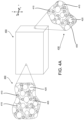
- FIGS. 4 A to 4 C are block diagrams illustrating an example strain-sensing composite polymer, according to an implementation.
- FIG. 5 is a block diagram that illustrates a shoe-based analysis system, according to an implementation.
- FIG. 6 is a flow diagram of a process for providing physical feedback using the shoe-based analysis system, according to an implementation.
- FIG. 7 is a flow diagram of a process for generating ground reaction force data using the shoe-based analysis system, according to an implementation.
- FIG. 8 is a flow diagram of a process for generating acceleration data using the shoe-based analysis system, according to an implementation.
- FIG. 9 is a flow diagram of a process for generating pressure data using the shoe-based analysis system, according to an implementation.
- FIG. 10 A to 10 C are charts illustrating correspondence of ground reaction force data from an exemplary shoe-based analysis system with laboratory ground reaction force data, according to an implementation.
- FIG. 1 is a cross-section that illustrates various parts of a typical athletic shoe.
- the bottom or sole of the shoe includes an outsole 120 that comes in direct contact with the ground.
- the outsole is conventionally made of leather, resin rubber, natural rubber, or a foam type of material.
- Foam outsoles are used in many athletic shoes.
- the sole also includes a midsole 115 that provides cushioning and pronation control.
- the midsole 115 is conventionally made of foam materials that provide comfort.
- the sole also includes an insole board 105 .
- the insole 105 can be made of cellulosic paper board or foam materials and can provide comfort and/or support.
- a shoe may also include a sock liner 110 .
- the sock liner 110 may be in direct contact with the foot or socks of the wearer and is sometimes designed to wick away moisture and provide additional cushioning.
- the sock liner can be covered by another insole (e.g., an inserted insole).
- the insole 105 is in direct contact with the foot or socks of the wearer.
- a shoe 100 can also include a tongue 130 .
- the tongue 130 provides cushioning at the top of the wearer's foot under the laces.
- the shoe may also include other areas of padding 135 , such as at the sides or back of the shoe.
- the padding 135 may be covered by a lining.
- a self-sensing composite polymer foam replaces all of, or portions of, the shoe that provide padding.
- the self-sensing composite polymer foam may replace all of or portions of the tongue 125 , the padding 135 , and/or the sock liner 110 , the insole 105 , the midsole 115 , or the outsole 120 of a shoe 100 .
- the self-sensing composite polymer foam may be non-additive in that the foam performs two functions simultaneously: as a sensor and as padding and/or support. For instance, all of or a portion of the foam already present in the shoe may be removed and replaced with the self-sensing composite polymer foam.
- the self-sensing composite polymeric foam may have a modulus or Young's modulus that matches that of the removed foam to provide the same support factor or damping as the existing foam.
- the self-sensing composite polymer foam may be an insole or orthotic that is later inserted into the shoe. Such a later-added insole is still non-additive as it functions as padding/support and a sensor.
- the composite polymeric foam mimics the physical properties of existing materials in the shoe and wearers of the shoe do not notice a difference between the shoe-based analysis system and a regular shoe that lacks the sensors.
- the self-sensing composite polymeric foam is a sensor because the self-sensing composite polymer foam is able to generate or modify an electrical signal (e.g. generating a voltage, or changing resistance) that can be measured when deformed. In this sense the composite polymer foam is strain-sensitive and or impact-sensitive.
- the self-sensing composite polymer may be a foam that generates a voltage (e.g., an electrical charge) when impacted and/or causes a change in resistance upon deformation.
- the self-sensing polymeric foam can both produce both resistive and electric voltage data simultaneously.
- the change in resistance may be used to measure strain and the electric voltage data may be used to measure impact (e.g., strain rate and total strain).
- the electrical data whether an electric voltage, resistance data, or both, that the self-sensing composite polymeric foam produces upon deformation can then be analyzed to determine one or more sequences or patterns of impact, the magnitude of impact, ground reaction force, the weight of the user, acceleration, pressure, and/or so forth. This information can then be used and/or processed to train the runner on desirable running form, track caloric output, train on proper kicking, and/or so forth. These mechanisms included in one or more shoes could also be used in physical rehabilitation, medical gait analysis, and/or so forth.
- FIG. 2 A to FIG. 2 B are diagrams that illustrate example placement of sensors in a shoe-based analysis system, according to an embodiment.
- portions of the sock liner 210 have been removed and replaced with self-sensing composite polymeric foam sensors 250 ( a ) and 250 ( b ).
- the two sensors 250 ( a ) and 250 ( b ) also function as the sock liner 210 , or are included as a part of the sock liner 210 .
- Each sensor 250 ( a ) and 250 ( b ) constitutes a separate sensor that can produce voltage data, in the form of voltage or a change in resistance.
- the shoe 200 may also include additional sensors 250 , e.g., at a position corresponding to the ball, toe, and/or arch of the foot, that are not illustrated in FIG. 2 A .
- One or more of the sensors 250 ( a ) and 250 ( b ) that replace portions of the shoe e.g., the sock liner 210 or insole 205
- the probes 255 may be a pair of wires made of any conductive material.
- the microcontrollers are configured to monitor, for example, voltage or another electrical property such as resistance. In the example of FIG.
- FIG. 2 A foam in the sock liner 210 was removed and replaced with foam sensors 250 ( a ) and 250 ( b ) as described herein. While FIG. 2 A illustrates replacement of portions of the sock liner 210 , sensors 250 ( a ) and 250 ( b ) may also replace portions of the insole 105 , the midsole 115 or the outsole 120 . In addition, the sensors, or in other words the self-sensing polymeric foam, may be shaped to replace other padded areas, such as padding 135 and/or tongue 125 .
- the probes 255 (which can include, for example, a wire, a contact, etc.) are coupled to (e.g., run between) the sensors 250 and a microcontroller, such as microcontroller 260 illustrated in FIG. 2 B .
- the probes 255 may run between the lining of the shoe 200 and the outside of the shoe 200 to the tongue 230 where the microcontroller 260 is placed to monitor the voltage data from all of the sensors.
- the microcontroller 260 could also be placed elsewhere, for example, in the heel of the shoe 200 or the padding of the shoe 200 .
- Each sensor e.g., the self-sensing composite polymeric foam, is capable of producing both a piezoelectric and a piezoresistive response.
- the microcontroller 260 can measure both resistive and electric voltage data from each sensor.
- the foam padding of the tongue 230 may be replaced with self-sensing polymeric foam as another sensor 250 .
- the self-sensing polymeric foam 250 replaces the foam in the tongue 230 , the energy that is transmitted to a ball when kicked could be determined.
- the composite polymeric foam could also be placed in the midsole 115 with the sock liner 110 and/or insole 105 covering it to add a level of element separation between the foot of the wearer and the sensor 250 to increase reliability of the sensors 250 .
- FIGS. 2 A and 2 B are presented by way of example only.
- the various components described above could be modified and/or included in different portions of the shoe.
- the tongue 230 and the sock liner 210 may have their own microcontroller.
- additional or less microcontrollers, foam sensors, and/or wires could be included or excluded in the shoe-based analysis system.
- FIG. 3 illustrates another example placement of self-sensing composite polymer foam in a shoe based analysis system.
- the sensor 350 i.e., the self-sensing composite polymer foam
- the insole 300 is self-contained and may be added to the shoe after purchase, e.g., added by the wearer of the shoe.
- the insole 200 may be included in the shoe as it is manufactured. In either case the insole still functions as padding and/or support for the wearer in addition to functioning as a sensor.
- FIG. 3 illustrates another example placement of self-sensing composite polymer foam in a shoe based analysis system.
- the sensor 350 i.e., the self-sensing composite polymer foam
- the insole 300 is self-con
- the microcontroller 360 is included in the insole 305 itself.
- Probes 355 are inserted into the sensor 350 at locations that measure voltage data corresponding to the toe, ball, inner arch, and heel of the wearer's foot.
- the sensor 350 and probes 355 provides four points for voltage data collection.
- the sensor 350 is capable of generating or producing a voltage, e.g. an electrical charge, in response to deformation in addition to producing a change in resistance in response to deformation.
- the four probes 355 may provide eight different sources of data.
- the sensor 350 may replace the entire insole 305 and the microcontroller 360 may be located elsewhere in the shoe, e.g., the tongue, a sidewall, or another layer of the sole (e.g., the midsole or wedge).
- FIGS. 4 A to 4 C are block diagrams illustrating an example strain-sensing composite polymer foam 450 , according to an implementation.
- the composite polymer foam 450 can be used as a sensor, e.g., sensors 250 ( a ) and 250 ( b ) of FIG. 2 A or sensor 350 of FIG. 3 .
- FIG. 4 A is a high-level schematic diagram of a self-sensing composite polymeric foam 450 that exhibits a piezoelectric response and a negative piezoresistive effect to deformation, e.g., compression and relaxation, according to one implementation.
- the composite polymeric foam 450 also exhibits a piezoelectric response and/or piezoresistivity in response to tensile strain.
- the composite polymeric foam 450 may include several components: a matrix 405 with one or more conductive fillers (e.g., conductive nanoparticles 410 , conductive stabilizers 415 ), and voids 420 .
- the voids 420 and conductive fillers may be uniformly dispersed throughout the matrix.
- the matrix 405 may be any polymer, such as a silicone-based material, an elastomer, a polyurethane material, EVA (ethylvinyl acetate), polyethylene, SBR (styrene butadiene rubber), neoprene, latex, or other foam-like material, etc., that retains its shape after deformation and includes voids 420 throughout the material.
- the matrix 405 is comprised of material that has elasticity, porosity, and high failure strain, typically from 50% to 1000% strain.
- the polymer matrix 405 may be a foam-based product that forms voids 420 , for example through a chemical reaction, introduction of a foaming agent, through gas injection, etc.
- the voids 420 may give the composite polymeric foam 450 relatively low weight, relatively low density, and relatively high energy absorption.
- the voids 420 are dispersed throughout the matrix 405 .
- the density of the polymer used for matrix 405 may be approximately two to forty times greater without the voids than with the voids.
- the composite polymeric foam 450 may have a density from 30 kg/m 3 to 800 kg/m 3 .
- the composite polymeric foam 450 may also have porosity due to the voids 420 .
- the porosity of the composite polymeric foam 450 may be defined in terms of the volume fraction of air and the size of the voids 420 .
- Each of these elements may be affected by several factors, including the polymer used as the matrix 405 , the process used to form the voids 420 , confinement of the composite polymeric foam 450 during formation of the voids and/or curing (e.g., size and shape of a mold and amount of composite material introduced into the mold), and the amount and type of the conductive fillers mixed with the polymer, etc.
- inclusion of conductive nanoparticles 410 tends to decrease the size of the voids 420 .
- Voids may be open-cell (e.g., the voids may run into or connect with each other) or closed-cell (e.g., the voids are separate from each other) and can vary in size depending on a number of factors. In some implementations the voids 420 may range in size up to 1000 ⁇ m.
- the polymer used as the matrix 405 may be capable of being mixed with conductive fillers prior to curing.
- some polymeric foams may be thermoset, or irreversibly cured via heat, a chemical reaction, or irradiation.
- conductive fillers Prior to curing, conductive fillers may be combined with the uncured polymer.
- a polymer cured via a chemical reaction, such as foam may include two parts, the polymer foam being formed when the two parts are mixed or combined. Once combined, the two parts chemically react, generating the air pockets or voids characteristic of foam, and harden.
- Conductive fillers may be mixed with one or both parts prior to combining.
- Some polymers may be mixed with a foaming agent prior to curing.
- Such polymeric foams may be combined with conductive fillers prior to mixing with the foaming agent.
- Voids may be formed in the composite polymeric foam by gas injection, by whipping, etc. Some polymers may be cured via heat. Thermoset polymeric foams may be cast, molded, sprayed or extruded after mixing and before they cure.
- the composite polymeric foam 450 can be shaped according to the requirements of the portion of the shoe that it replaces.
- the conductive filler may include conductive nanoparticles 410 .
- Conductive nanoparticles 410 are particles with at least one dimension that measures 1.5 microns or less and that are also made from a material that conducts electricity. Examples of such conductive materials include nickel, platinum, gold, silver, copper, carbon, (e.g., carbon nanotubes, carbon black, graphite, etc.) etc. Examples of conductive nanoparticles 410 include nanowires, powders, and nanostrands. Examples of nanostrands that can be included is a nickel nanostrand (NiN) and Novamet 525. NiNs are available from Conductive Composites, LLC (Heber City, Utah) and are described by U.S. Pat. No.
- the conductive filler may also include a plurality of conductive stabilizers 415 .
- the conductive stabilizers 415 may also be added to the uncured polymer prior to formation of the voids.
- the conductive stabilizers 415 may be any conductive material that acts as a stabilizer.
- the conductive stabilizers 415 may be carbon fibers.
- the conductive stabilizers 415 may be fibers coated with a material that conducts electricity.
- the conductive stabilizers 415 may be fibers coated with pure nickel.
- the fibers may be coated approximately 20-40% by weight with the conductive material.
- the fibers may be cut to short lengths, for example from 0.1 to 1 mm.
- the fibers may have a diameter of up to 10 ⁇ m (e.g., 0.2 ⁇ m, 1 ⁇ m, 5 ⁇ m, 8 ⁇ m). In some implementations, the fibers may be hollow (e.g., tubes).
- the conductive stabilizers 415 may increase the strength and energy absorption capabilities of the composite polymeric foam 450 .
- the conductive nanoparticles 410 may also increase the strength and energy absorption capabilities of the composite polymeric foam 450 , but typically to a lesser extent than the conductive stabilizers 415 .
- the conductive nanoparticles 410 may be a primary conductive filler and the conductive stabilizers 415 may be a secondary conductive filler.
- the composite polymeric foam 450 is uniform. Put another way, the composite polymeric foam 450 , and thus the sensor, does not have layers and its composition is generally consistent at a macroscopic (e.g., naked eye) level from outer surface (outer wall) to outer surface. In some implementations, the composite polymeric foam 450 may also have isotropic properties at a macroscopic level in that it does not exhibit a preferred directionality.
- a macroscopic e.g., naked eye
- the composite polymeric foam 450 may also have isotropic properties at a macroscopic level in that it does not exhibit a preferred directionality.
- the composite polymeric foam 450 may exhibit piezoelectric response or piezoresistivity along the x-axis, the y-axis, and the z-axis, which are illustrated in FIG. 4 A .
- the composite polymeric foam 450 may exhibit piezoelectric response or piezoresistivity detectable from one outer surface of the material to another outer surface, regardless of which outer surfaces are used.
- the composite polymeric foam 450 may have anisotropic properties.
- the conductive fillers may be aligned in a particular direction to gain better measurements in that particular direction. Alignment of the conductive fillers can be accomplished through the manufacturing process like extruding the product through a hose.
- the conductive nanoparticles 410 and the conductive stabilizers 415 may not be easily visible without magnification, such as magnification areas 430 and 440 .
- magnification areas 430 and 440 the components of the composite polymeric foam 450 may be distinguishable, but may be generally dispersed in a consistent or even manner along any axis.
- the general composition of areas 430 and 440 are similar even at the microscopic level.
- the composite polymeric foam 450 can exhibit negative piezoresistivity and a piezoelectric response to an impact or other deformation applied along any axis, such as the x axis, the y axis, and the z axis.
- the measured electrical response is consistent in any direction over a same distance. For example, if an electrical response is detected along a first axis, a same distance is any distance within a sphere where the first axis is the diameter.
- composite polymeric foam 450 that is isotropic is not limited to measuring impacts that arrive from a predetermined orientation with respect to the composite polymeric foam 450 .
- composite polymeric foam 450 is anisotropic the composite polymeric foam 450 may measure impacts arriving from a predetermined orientation more accurately.
- a material that exhibits a piezoresistive effect changes electrical resistance when compressed.
- a sensor with a negative piezoresistive effect becomes less resistant with increased strain, meaning a current will flow more easily through the material when compressed than through the material in its resting state.
- a gauge with a positive piezoresistive effect becomes more resistant with increased strain, meaning a current will not flow as easily.
- Traditional strain sensors measure strain by utilizing positive piezoresistivity; i.e., the electrical resistance increases with increased strain. The increased resistance in traditional strain gauges occurs due to Poisson-thinning of the strain gauge material.
- a current producing device such as a battery
- a sensor with a negative piezoresistive effect may be desirable for many applications since it will draw little or no current when the material is not strained, potentially prolonging the service time for battery powered applications.
- the change in electrical resistance is one type of electrical response to pressure/impact.
- a material that produces a piezoelectric response generates electric potential, in the form of a voltage that can be measured when deformed.
- a material that produces a piezoelectric response may generate a voltage that can be measured without the need for an external current producing device.
- the voltage generated is another type of electrical response to impact.
- a material that exhibits a piezoresistive effect does not automatically produce a piezoelectric response and vice versa.
- composite polymeric foam 450 can exhibit both piezoresistive and piezoelectric responses.
- the shoe based analysis system may use piezoresistive voltage data to measure strain whereas the shoe-based analysis system may use piezoelectric voltage data to measure impact, i.e. both strain rate and total strain.
- the piezoresistive voltage data provides better feedback when the strain activity is slower, while the piezoelectric voltage data provides better feedback for faster impacts.
- the shoe-based analysis system may combine the piezoresistive and piezoelectric information for superior measurements.
- the composite polymeric foam 450 can exhibit improved thermal conductivity.
- the matrix 405 may have low thermal conductivity, making the matrix 405 an insulator.
- the addition of a small percentage of conductive stabilizers 415 for example from 0.05% to 7.0% by weight, the thermal conductivity of the composite polymeric foam greatly increases without adversely affecting the mechanical material properties or feel of the matrix 405 .
- the composite polymer foam 450 can conduct heat away from the foot of the wearer.
- the amount of conductive stabilizers 415 is approximately 0.05% to 7.0% of the weight of the polymer matrix 405 .
- the load weight may be dependent on the length of the conductive fibers. At higher load weights the inclusion of the conductive stabilizers 415 may adversely affect the material properties of the resulting composite polymer foam 450 .
- the composite polymeric foam 450 is capable of being sculpted in any direction without affecting the piezoelectric response or the piezoresistive effect of the composite material because it is uniform between outer surfaces.
- the composite polymeric foam 450 does not include layers, it may be cast and then cut or sculpted in any direction without affecting its ability to act as a piezoelectric or piezoresistive sensor.
- a large sheet or block of the material may be manufactured and many sensors cut or formed from the same sheet.
- the composite polymeric foam 450 once cured, does not need to be charged; the piezoelectric response is inherent in the composite polymeric foam 450 itself.
- the composite polymeric foam 450 Due to the elasticity of the matrix 405 , the composite polymeric foam 450 is able to measure 80% strain without permanent deformation. This makes the composite polymeric foam 450 useful as a sensor in a shoe, which can experience strains on the order of 5% to 50%.
- FIG. 4 B illustrates an implementation of composite polymeric foam 450 that includes the polymer matrix 405 , voids 420 , and the conductive nanoparticles 410 as the conductive filler without the conductive stabilizer.
- FIG. 41 C illustrates another implementation of composite polymeric foam 450 that includes the polymer matrix 405 , the voids 420 , and the conductive stabilizers 415 as the conductive filler without the conductive nanoparticles.
- the variations of composite polymeric foam 450 illustrated in FIGS. 4 A through 4 C all exhibit a piezoelectric response and have negative piezoresistivity.
- the amounts and types of conductive fillers used affect the amount of energy absorption of the composite polymeric foam 450 , the cost of the composite polymeric foam 450 , the strength of the piezoresistive effect, the strength of the piezoelectric response, etc. It is recognized that the amounts and ratios may be dependent on many factors, such as the function of the composite material as padding or protection, the desired cost, the anticipated amplitude of impacts, etc. However, to exhibit the piezoelectric response the conductive fillers are generally 22% or less of the weight of the resulting composite polymeric foam 450 . In some implementations, the conductive stabilizers may be generally up to 7% of the weight. In some implementations, the conductive nanoparticles 410 may generally be up to 15% of the weight.
- FIG. 5 is a high-level block diagram that illustrates a shoe-based analysis system 590 , according to an implementation.
- the system 590 includes a shoe 500 that includes self-sensing composite polymer foam 550 .
- the composite polymer foam 550 replaces a portion of or all of the foam material in at least one part of the shoe 500 .
- the composite polymer foam 550 may replace one or more portions of the sock liner, the insole, the midsole, the outsole, the tongue, or any other padding in the shoe.
- the composite polymeric foam 550 may thus function as a padded insert as well as a sensor.
- the composite polymeric foam 550 may be composite polymeric foam 450 described with respect to FIGS. 4 A through 4 C .
- the composite polymeric foam 550 may be sensors 250 ( a ) or 250 ( b ) of FIG. 2 A or sensor 350 of FIG. 3 . Although illustrated as one sensor 550 , implementations may include multiple sensors, e.g., multiple distinct areas of composite polymeric foam 550 . Thus composite polymeric foam 550 represents one or more sensors in the shoe 500 .
- the shoe 500 may include one or more voltage detectors 555 operatively coupled to the composite polymeric foam 550 . In some implementations, the voltage detector 555 may be coupled to the composite polymeric foam 550 via one or more pairs of wires or other probes disposed in the composite polymeric foam 550 .
- the shoe 500 may include a plurality of voltage detectors 555 , operatively coupled to respective sensors (e.g., sensor 250 ( a ) and sensor 250 ( b ) of FIG. 2 A may each have a respective voltage detector 555 ) or to a single sensor (e.g., sensor 350 of FIG. 3 may be coupled to multiple voltage detectors 555 ).
- the voltage detector 555 may be capable of detecting voltage generated by the composite polymeric foam 550 when the composite polymeric foam 550 experiences strain, for example due to an impact.
- the voltage detector 555 may also be capable of detecting a decrease in electrical resistance when the composite polymeric foam 550 experiences strain, for example due to an impact.
- the shoe 500 may include a voltage source (e.g., a battery, not shown).
- the voltage detector 555 may be any device that detects or uses voltage and produces a value that can be stored and/or compared.
- the voltage detector 555 may also include other components (not shown), such as memory and/or a processor, (e.g., a processor formed in a substrate).
- the voltage detector 555 may be operatively coupled to or included in a microcontroller 560 .
- the microcontroller 560 may include a memory 534 and/or a transmitter 536 .
- the memory 534 may be any type of volatile or non-volatile memory capable of storing voltage data.
- the voltage detector 555 may be capable of converting detected voltage into a value that is stored in the memory 534 .
- the memory 534 may be a component of the voltage detector 555 .
- the memory 534 may store additional information with the voltage value, such as the date and/or time the value was detected.
- the additional information may include an identifier of the voltage detector that detected the value.
- the memory 534 may also store other information with the voltage value.
- the voltage value and additional information, if any, are considered voltage data.
- the memory 534 may store voltage data detected after a strain event, such as an impact received by the composite polymeric foam 550 .
- the memory 534 may store a plurality of voltage data, representing a plurality of strain events.
- the memory 534 may store the plurality of voltage data until it is transmitted to a computing device, either wirelessly or via a wired connection.
- the memory 534 may also store profile data.
- the profile data may represent a series of values representing compression events having a target or ideal sequence.
- the profile data may represent ground reaction force data for an ideal sprinting stride, during an ideal hurdle stride, during an ideal walking stride, during an ideal golf swing, etc.
- the ground reaction force data may represent the force at different points on the foot, e.g., at the heel, at the toe, at the ball, at the inner arch, and/or the outer arch, etc.
- the microcontroller may include transfer function 538 .
- Transfer function 538 represents instructions that, when executed by the microcontroller 560 , converts the voltage data from the voltage detector 555 to force data, such as ground reaction force, pressure, acceleration, etc. Each different type of force may have a corresponding transfer function 538 . Thus, the transfer function for ground reaction force differs from the transfer function for pressure.
- the microcontroller may also include an analysis module 540 configured to compare the force data, or in other words the converted voltage data generated by the composite polymeric foam 550 , to a profile.
- the analysis module 540 may be configured to initiate feedback via a physical feedback device that alerts the wearer of the shoe 500 .
- the physical feedback device can be included in the shoe 500 , such as physical feedback device 565 or can be on a remote computing device, such as physical feedback device 570 or 588 .
- the physical feedback device 565 in the shoe 500 may be a device that vibrates, produces sound, displays a pattern of light, etc.
- the pattern of light can be a light of a specific color, two lights displaying a combination of colors, a solid color light that flashes in a pattern, etc.
- the vibration sequence, the sounds, or the light pattern indicates to the wearer either that the wearer's movements differ from the profile.
- the vibration sequence, sounds, or light pattern may indicate a specific problem with the wearer's movements. For example, a blue light may indicate incorrect heel strike, a yellow light too much pronation, an orange light not enough acceleration, etc. Similar vibration sequences, e.g., two quick pulses for improper heel strike, one long vibration for improper pronation, or sounds can be used to differentiate different problems.
- the microcontroller 560 may have a wired or wireless connection with the physical feedback device.
- the memory 534 , transfer function 538 , and/or analysis module 540 may be operatively coupled to a transmitter 536 .
- the transmitter 536 may be capable of transmitting data wirelessly to a computing device 580 or a physical feedback device, such as device 565 or device 570 .
- the microcontroller 560 may thus be a wireless microcontroller, for example the RFdigital RFduino.
- the transmitter 536 may transmit the voltage data or a feedback signal, e.g., which type of feedback to provide, in response to data being stored in the memory 534 .
- the voltage data or feedback signal may be wirelessly transmitted in real-time.
- the transmitter 536 may transmit the feedback signal in response to identifying differences between a profile and voltage data or force data.
- the microcontroller 560 may not include transfer function 538 and/or analysis module 540 .
- the shoe 500 may not include physical feedback device 565 . In such an implementation, the transmitter 536 may transmit the voltage data as soon as the transmitter 536 receives voltage data or force data.
- the transmitter 536 may transmit voltage data, force data, and/or a feedback signal to a computing device 580 .
- the computing device 580 may be an external computing device, separate from the shoe 500 .
- the computing device 580 may include a receiver 581 .
- the computing device 580 may be any type of computing device, such as a controller (e.g., a processor, a microcontroller, etc.), a tablet, a laptop, a smart phone, a server, personal computer, a television with a processor, a smart watch or other wearable computing devices such as a fitness tracker or glasses, etc.
- the computing device 580 may include one or more transfer functions 586 .
- the transfer functions 586 may be configured to translate the voltage data generated by the composite polymeric foam 550 into one of several types of mechanical data, e.g., ground reaction force, pressure, acceleration, leg stiffness, etc.
- the transfer function 586 may have access to calibration data 583 that enables the transfer function 586 to convert the voltage data into the aforementioned mechanical data.
- the transfer function 586 may have access to calibration data 583 that enables the transfer function 586 to convert the voltage data into energy expenditure data.
- the transfer function may depend upon single or multiple voltage or electrical resistance inputs which are combined through the use of statistical methods such as basis expansions (e.g., functional data analysis) and regression or similar statistical tools to provide a calibrated force, strain, or displacement reading.
- the individual vector components of the ground reaction force may be computed based on algebraic combination of voltage inputs from several self-sensing polymeric foam inserts located in various locations on the shoe.
- the transfer function 586 may be or may include a machine learning algorithm that has been trained on patterns identified in the voltage data.
- the transfer function may also be adapted “real-time” based on a machine learning algorithm that identifies and removes noise and drift from the input signals.
- the transfer function may include a machine learning algorithm that finds patterns in the voltage data provided and identifies key points that correlate to mechanical data (e.g., acceleration, energy expenditure, leg stiffness, pressure, ground reaction force, etc.).
- the transfer functions 586 can be excluded, for example when transfer functions 538 exist. In some implementations, the transfer functions 586 may coordinate with transfer functions 538 . In some implementations, the shoe 500 may include transfer function 538 that has the capabilities of transfer function 586 when memory 534 stores the calibration data 583 .
- the computing device 580 may also include a calibration data 583 .
- the calibration data 583 may be used by the transfer function 586 (or 538 ) to analyze and interpret the voltage data.
- the calibration data 583 may be provided to the computing device 580 .
- the computing device 580 may include a module (not shown) that collects and stores the calibration data 583 .
- the calibration data 583 may represent force data, strain/displacement data, or energy expenditure data.
- composition of the composite polymeric foam 550 for example the amount of conductive nanoparticles and the amount of conductive stabilizers, can affect the piezoresistive and piezoelectric properties of the composite polymeric foam 550 , composite polymeric foam 550 that is manufactured outside of a controlled environment (e.g., outside of an established manufacturing process) may need to be calibrated after each manufacture.
- Composite polymeric foam 550 that is manufactured in a controlled environment may need to be calibrated after every manufacture.
- the computing device 580 may also include analysis module 587 .
- the analysis module 587 may use force data from one or more transfer functions 586 and compare the force data (i.e., generated from the voltage data produced by the composite polymeric foam 550 ) to an activity profile in profile data 584 .
- the profile data 584 may represent a series of values representing compression events having a target or ideal sequence.
- a profile in the profile data 584 may represent ground reaction force data, pressure data, and/or acceleration data for an ideal sprinting stride
- another profile in the profile data may represent ground reaction force data, pressure data, and/or acceleration data for an ideal hurdle stride
- another profile may represent an ideal walking stride
- another profile may represent an ideal golf swing, etc.
- the force data in a profile may represent the force at different points on the foot during the motion, e.g., at the heel, at the toe, at the ball, at the arch, and/or opposite the arch, etc., during a series of steps or pedaling.
- the analysis module 587 may be configured to compare force data from the shoe 500 with one or more profiles in real time, e.g., as the wearer of the shoe 500 is sprinting, is pedaling, or is walking. When the analysis module 587 identifies a difference between the force data from the shoe 500 and the profile, the analysis module 587 may provide a feedback signal to a physical feedback device.
- the feedback signal may be a particular vibration pattern, a sound, a light pattern, or an image (including text) to display.
- the physical feedback device can be part of the shoe 500 , part of computing device 580 , or another physical feedback device 570 .
- physical feedback device 565 may be excluded when physical feedback device 588 receives the feedback signal.
- physical feedback device 588 may be excluded when physical feedback device 565 receives the feedback signal.
- physical feedback device 588 and physical feedback device 565 may be eliminated when physical feedback device 570 receives the feedback signal.
- the physical feedback device 565 , the physical feedback device 588 , and/or the physical feedback device 570 may coordinate, e.g., they may each receive a feedback signal and provide feedback to the wearer. In some such implementations each device may provide a different type of feedback.
- one or more of the functions of the analysis module 587 is included in the shoe 500 , e.g., as analysis module 540 .
- module 540 and module 587 may coordinate.
- the analysis module 587 may be excluded and analysis module 540 may perform the functions described above.
- the analysis module 540 may be eliminated.
- the shoe 500 may provide feedback for orthopedic fittings, training and caloric output, etc. using computing device 580 .
- the shoe 500 may store a plurality of voltage data, corresponding to respective impact events, that is transmitted to computing device 580 at the request of a user, an external computer, etc.
- the shoe 500 may provide real-time biometric feedback to help a wearer correct stride, gait, or other form.
- the shoe 500 may include all hardware and software, e.g., transfer function 538 , profile data 584 , physical feedback device 565 , to provide the feedback.
- the shoe 500 may communicate with the computing device 580 to determine the feedback.
- the shoe 500 may determine the feedback and may initiate the feedback, e.g., via communication with an external physical feedback device 570 that provides the physical feedback.
- the physical feedback device 570 may be a wearable item that has the ability to vibrate, play sounds, or display lights or information to the wearer.
- a computing device 580 that is separate from shoe 500 is not needed.
- FIG. 6 is a flow diagram of an example process 600 for providing physical feedback using the shoe-based analysis system, according to an implementation.
- Process 600 may be used in a shoe-based analysis system, such as system 590 of FIG. 5 , to provide real-time feedback to the wearer of the shoe during physical activity, such as sprinting, kicking, walking, golfing, etc.
- Process 600 enables the wearer of the shoe to correct form while the wearer performs the activity. For example the feedback enables the wearer to determine incorrect stride, gait, weight shifting (e.g., during a golf swing), etc.
- Process 600 is understood to execute continuously once started until interrupted. In this manner, process 600 can provide continuous feedback during a particular physical activity session.
- the voltage data produced during the activity session may be stored or transmitted, wirelessly or via a wired connection, to a computing device for storage and further analysis.
- Process 600 begins with the system receiving voltage data produced by a strain-sensitive composite polymer foam in a shoe ( 605 ).
- the strain-sensitive composite polymer foam may replace at least a portion of existing foam in the shoe or may be an insert (e.g., insole insert or a heel insert).
- the strain-sensitive composite polymer foam may function as padding in the shoe.
- the strain-sensitive composite polymer foam may be composite polymer foam 450 of FIG. 4 .
- the composite polymer foam is able to produce or generate both piezoresistive and piezoelectric responses to deformation events. Voltage data may be produced at each site where a probe is disposed in the composite polymer foam.
- the shoe may have multiple portions of existing foam replaced with the composite polymer foam, or the composite polymer foam may have multiple probes disposed therein.
- the probes may correspond to a particular part of the wearer's foot.
- the probes may correspond to the toes, the ball, the heel, the top, the sides, etc. depending on the placement of the composite polymeric foam in the shoe and the placement of the probes in the composite polymeric foam.
- the system may convert the voltage data to force data ( 610 ).
- the system may have at least one transfer function for converting the voltage data to a particular kind of force. For example, one transfer function may convert the voltage data to ground reaction force data. Another transfer function may convert the voltage data to pressure data. Because the composite polymeric foam can produce both piezoelectric and piezoresistive data concurrently from a single deformation event, the system may calculate both pressure data and ground reaction force data from the same voltage data. The transfer functions are discussed in more detail with regard to FIGS. 7 to 9 .
- the system may compare the force data to an activity profile ( 615 ).
- the profile may represent ideal force data for a particular activity.
- the profile may include data corresponding to particular portions of the foot, e.g., values that correspond to the toes, the ball, the heel, etc. In other words, the profile data may have values that correspond to the different probe locations.
- the system may determine whether the force data obtained using the composite polymer foam falls within a threshold of the profile ( 620 ). In other words, the system may compare the force data for each foot location to corresponding profile data. If all values are within the threshold ( 620 , Yes), the system may continue receiving voltage data ( 605 ).
- an error may represent any value that falls outside the threshold.
- an error may correspond to a particular part of the foot, or in other words to a particular probe location.
- the system may provide a feedback signal corresponding to the error ( 630 ).
- any error may correspond with the same feedback signal.
- the system may be configured to provide a different feedback signal for each specific error. In other words, the system may be able to provide feedback that indicates to the wearer exactly how the physical activity fails to conform to the profile.
- the feedback signal may indicate that the force has been applied to a location of the foot that may increase injury risk or decrease performance.
- Other measures that may be of interest and measured by the shoe include: stride rate, stride length, braking or impulsive propulsion, leg stiffness and changes in momentum. Such measures may be used, for example, to objectively measure gait-related tasks that must be passed before a patient is discharged from the hospital.
- the feedback signal may indicate that weight was too far forward on the back foot.
- the feedback signal might indicate that an osteoarthritic patient is moving in a way that unnecessarily increases ground reaction force or pressure, and increases the rate of disease progression.
- the physical feedback device may continue to provide the feedback (e.g., continue to play the sound or display the light pattern) until the force data is within the threshold for the profile data.
- FIG. 7 is a flow diagram of an example process 700 for generating ground reaction force data using the shoe-based analysis system, according to an implementation.
- Process 700 may be executed by a shoe-based analysis system, such as system 590 of FIG. 5 .
- Process 700 generates ground reaction force data that correlates to the ground reaction force data conventionally obtained in very expensive laboratory settings. However, process 700 takes place outside of any laboratory using a shoe with at least some of its foam padding (e.g., in the sole, tongue, sides, etc.) replaced with strain-sensitive composite polymer foam.
- the ground reaction force data obtained in a laboratory setting has been used to diagnose fatigue, depression, injury, concussion, Parkinson's, Alzheimer's, etc. Because the ground reaction force data generated by the shoe-based analysis system, e.g., system 590 , correlates to the data generated in a laboratory, these same types of diagnoses can result from process 700 .
- Process 700 may begin with the system receiving voltage data produced by a strain-sensitive composite polymer foam in a shoe ( 705 ).
- the strain-sensitive composite polymer foam may replace at least a portion of existing foam in the shoe or may be an insert (e.g., insole insert or a heel insert).
- the strain-sensitive composite polymer foam may function as padding in the shoe.
- the strain-sensitive composite polymer foam may be composite polymer foam 450 of FIG. 4 .
- the composite polymer foam is able to produce or generate both piezoresistive and piezoelectric responses to deformation events. Voltage data may be produced at each site where a probe is disposed in the composite polymer foam.
- the shoe may have multiple portions of existing foam replaced with the composite polymer foam, or the composite polymer foam may have multiple probes disposed therein.
- the probes may correspond to a particular part of the wearer's foot.
- the probes may correspond to the toes, the ball, the heel, the top, the sides, etc. depending on the placement of the composite polymeric foam in the shoe and the placement of the probes in the composite polymeric foam.
- the system may convert the voltage data to ground reaction force data ( 710 ). Converting the voltage data to ground reaction force data, or other data such as acceleration data or pressure data, may occur through the use of statistical methods such as basis expansions (e.g., functional data analysis) and regression or similar statistical tools.
- basis expansions e.g., functional data analysis
- the system begins with shoe sensor data, i.e., the voltage data produced by the composite polymeric foam, and GRF data for a collection of training stances.
- the GRF data for a collection of training stances is training data obtained in a laboratory setting.
- the system may filter the shoe sensor data with a Butterworth filter and then apply functional data analysis tools to create functional representations of the shoe sensor curves and GRF curves.
- the system may use any basis expansion (wavelets, B-splines, other Fourier-based methods, etc.) to represent the shoe sensor curves.
- the associated predicted GRF (or acceleration or pressure) curve can be obtained by reconstructing a curve from ⁇ .
- the conversion takes place on a microcontroller in the shoe.
- the shoe may include a microcontroller that transmits the voltage data to another computing device where the conversion takes place.
- the system may store the ground reaction force data in a memory ( 715 ).
- the shoe may include memory in which the ground reaction force data is stored.
- the shoe may transmit the ground reaction force data to another computing device for storage.
- the ground reaction force data may represent data corresponding to particular parts of the foot, or a resultant ground reaction force vector that is applied to the foot at the center of pressure.
- the ground reaction force data may include components related to the toes, ball, heel, inner arch, outer arch, etc., depending on the location of the composite polymer foam and the placement of probes in the composite polymer foam.
- the system may determine whether it is finished collecting data ( 720 ). For example, the system may collect data for a specific time period or until it receives an explicit command to stop. In some implementations, the explicit command may be a command to transfer the saved data. If it is not finished ( 720 , No), the system continues receiving voltage data ( 705 ). If the system is finished ( 720 , Yes), the system may perform analysis of the ground reaction force data ( 725 ). The analysis can include analysis that results in the diagnoses addressed above, as well as additional analysis, such as determining the weight of the wearer, deterring caloric burn during a session, the height of a jump, cadence, stride length, propulsion, braking, etc.
- FIG. 8 is a flow diagram of an example process 800 for generating acceleration data using the shoe-based analysis system, according to an implementation.
- Process 800 may be executed by a shoe-based analysis system, such as system 590 of FIG. 5 .
- Process 800 generates acceleration data that correlates to acceleration data conventionally obtained in very expensive laboratory settings.
- process 800 takes place outside of any laboratory using a shoe with at least some of its foam padding (e.g., in the sole, tongue, sides, etc.) replaced with strain-sensitive composite polymer foam.
- the acceleration data obtained in a laboratory setting has been used to learn more about forces and motion, during human motion, that relate to increased human performance or injury risk.
- Process 800 may be run concurrently with process 700 because the voltage data can be provided to two different transfer functions simultaneously.
- Process 800 may begin with the system receiving voltage data produced by a strain-sensitive composite polymer foam in a shoe ( 805 ).
- the strain-sensitive composite polymer foam may be composite polymer foam 450 of FIG. 4 .
- Voltage data may be produced at each site where a probe is disposed in the composite polymer foam.
- the shoe may have multiple portions of existing foam replaced with the composite polymer foam, or the composite polymer foam may have multiple probes disposed therein.
- the probes may correspond to a particular part of the wearer's foot.
- the probes may correspond to the toes, the ball, the heel, the top, the sides, etc. depending on the placement of the composite polymeric foam in the shoe and the placement of the probes in the composite polymeric foam.
- the system may convert the voltage data to acceleration data ( 810 ).
- the system may use a transfer function that has been trained using a machine learning algorithm to find key data points in the voltage data generated by the composite polymer foam.
- converting the voltage data to acceleration data may occur through the use of statistical methods such as basis expansions (e.g., functional data analysis) and regression or similar statistical tools.
- the conversion takes place on a microcontroller in the shoe.
- the shoe may include a microcontroller that transmits the voltage data to another computing device where the conversion takes place.
- the system may store the acceleration data in a memory ( 815 ).
- the shoe may include memory in which the acceleration data is stored.
- the shoe may transmit the acceleration data to another computing device for storage.
- the acceleration data may represent data corresponding to particular parts of the foot.
- the acceleration data may include components related to the toes, ball, heel, inner arch, outer arch, etc., depending on the location of the composite polymer foam and the placement of probes in the composite polymer foam.
- the system may determine whether it is finished collecting data ( 820 ). For example, the system may collect data for a specific time period or until it receives an explicit command to stop. In some implementations, the explicit command may be a command to transfer the saved data. If it is not finished ( 820 , No), the system continues receiving voltage data ( 805 ). If the system is finished ( 820 , Yes), the system may perform analysis of acceleration data ( 825 ). The analysis can include, braking and propulsion measurements,
- FIG. 9 is a flow diagram of a process for generating pressure data using the shoe-based analysis system, according to an implementation.
- Process 900 may be executed by a shoe-based analysis system, such as system 590 of FIG. 5 .
- Process 900 generates pressure data that correlates to pressure data conventionally obtained by more expensive instruments that are often found in laboratory settings. However, process 900 takes place outside of any laboratory using a shoe with at least some of its foam padding (e.g., in the sole, tongue, sides, etc.) replaced with strain-sensitive composite polymer foam.
- the pressure data obtained in a laboratory setting has been used to evaluate human performance during various physical activity (e.g., running patterns), and diagnosis and treatment of various common pathologies (e.g., diabetic neuropathy).
- Process 900 may be run concurrently with process 700 and/or 800 because the same voltage data can be provided to multiple transfer functions.
- Process 900 may begin with the system receiving voltage data produced by a strain-sensitive composite polymer foam in a shoe ( 905 ).
- the strain-sensitive composite polymer foam may replace at least a portion of existing foam in the shoe or may be an insert (e.g., insole insert or a heel insert).
- the strain-sensitive composite polymer foam may function as padding in the shoe.
- the strain-sensitive composite polymer foam may be composite polymer foam 450 of FIG. 4 .
- replacement of the foam in the tongue of the shoe may enable the system to measure the force of a kick.
- Another example involves the measurement of and then subsequent decrease of high pressure that is applied to the heel of the foot of a patient who suffers from decubitus ulcers that are commonly secondary to other pathologies.
- Voltage data may be produced at each site where a probe is disposed in the composite polymer foam.
- the shoe may have multiple portions of existing foam replaced with the composite polymer foam, or the composite polymer foam may have multiple probes disposed therein.
- the probes may correspond to a particular part of the wearer's foot.
- the probes may correspond to the toes, the ball, the heel, the top, the sides, etc. depending on the placement of the composite polymeric foam in the shoe and the placement of the probes in the composite polymeric foam.
- the system may convert the voltage data to pressure data ( 910 ).
- the system may use a transfer function that has been trained using a machine learning algorithm to find key data points in the voltage data generated by the composite polymer foam.
- converting the voltage data to pressure data may occur through the use of statistical methods such as basis expansions (e.g., functional data analysis) and regression or similar statistical tools.
- the conversion takes place on a microcontroller in the shoe.
- the shoe may include a microcontroller that transmits the voltage data to another computing device where the conversion takes place.
- the system may store the pressure data in a memory ( 915 ).
- the shoe may include memory in which the pressure data is stored.
- the shoe may transmit the pressure data to another computing device for storage.
- the pressure data may represent data corresponding to particular parts of the foot.
- the pressure data may include components related to the toes, ball, heel, inner arch, outer arch, etc., depending on the location of the composite polymer foam and the placement of probes in the composite polymer foam.
- the system may determine whether it is finished collecting data ( 920 ). For example, the system may collect data for a specific time period or until it receives an explicit command to stop. In some implementations, the explicit command may be a command to transfer the saved data. If it is not finished ( 920 , No), the system continues receiving voltage data ( 905 ). If the system is finished ( 920 , Yes), the system may perform analysis of pressure data ( 925 ). The analysis can result in a quantification of pressure distribution across the entire plantar surface of the foot, which could be used to better understand various important characteristics of human performance and injury. The analysis would be helpful in various areas; e.g., a better understanding of movement efficacy in sport, more effective evaluations of acute concussion severity, or more understanding regarding the efficacy of a rehabilitative intervention designed to treat chronic ankle instability.
- Gait Analysis can be a valuable tool in the Assessment and Rehabilitation of current injuries as well as the prevention of future injuries.
- Gait Analysis may be provided during a patient's initial evaluation, and revisited during later sessions to monitor progress. Any of methods 700 , 800 , or 900 , alone or in combination, can be used as input for gait analysis.
- the voltage data may be provided to a ground reaction force transfer function and to a pressure transfer function.
- the resulting ground reaction force data and pressure data may be compared against respective profiles concurrently.
- the shoe-based analysis system may provide feedback, e.g., in the form of a feedback signal to a physical feedback device, for ground reaction force and pressure profiles at the same time as part of gait analysis.
- shoe-based analysis system could provide similar combined feedback for other types of mechanical data (e.g., ground reaction force and acceleration). Because the composite polymer foam sensors provide data for slower (e.g., piezoresistive) and faster (e.g., piezoelectric) strain events, and because the sensors are non-additive and essentially undetectable by the wearer, shoe-based analysis system provides a superior environment for collecting gait analysis data.
- mechanical data e.g., ground reaction force and acceleration
- FIGS. 10 A to 10 C are charts illustrating correspondence of ground reaction force data from an exemplary shoe-based analysis system with laboratory ground reaction force data, according to an implementation.
- the charts compare a ground reaction force data collected from a lab-based system with predicted ground reaction force data obtained from a shoe-based analysis system, e.g., the system 590 of FIG. 5 , that uses composite polymeric foam sensors.
- the actual lab-based ground reaction force data i.e., the solid line in FIGS. 10 A, 10 B, and 10 C , represents data obtained in an expensive laboratory setting, or in other words training data.
- the predicted GRF represents data obtained using the composite polymeric foam and a transform function.
- FIGS. 10 A, 10 B, and 10 C also illustrates the shoe-based prediction of the ground reaction force curve with a blue dashed line, with the prediction carried out using the approach outlined in paragraph 0054 above.
- the three figures are representations of three typical steps (stances) for ground reaction force in the vertical direction.
- FIG. 10 A illustrates a ground reaction force of a first typical step.
- FIG. 10 B illustrates ground reaction force of a second typical step.
- FIG. 10 C illustrates ground reaction force of a third typical step.
- the steps of FIGS. 10 A to 10 C may also represent three steps in an example profile of profile data, e.g., stored in profile data 584 of FIG. 5 .
- the profile that includes the three steps would likely include additional ground reaction force steps as well as pressure data for the steps and/or acceleration data for the steps.
- These graphs illustrate that the shoe-based analysis system can replicate ground reaction force data attached to any step.
- correlation with ground reaction force data obtained in laboratory settings means that shoe-based analysis system can provide high-quality ground reaction force data obtained in every-day settings that can be used to diagnose and correct many problems.
- Implementations of the various techniques described herein may be implemented in digital electronic circuitry, or in computer hardware, firmware, software, or in combinations of them. Implementations may implemented as a computer program product, i.e., a computer program tangibly embodied in an information carrier, e.g., in a machine-readable storage device (computer-readable medium) or in a propagated signal, for processing by, or to control the operation of, data processing apparatus, e.g., a programmable processor, a computer, or multiple computers.
- a computer program product i.e., a computer program tangibly embodied in an information carrier, e.g., in a machine-readable storage device (computer-readable medium) or in a propagated signal, for processing by, or to control the operation of, data processing apparatus, e.g., a programmable processor, a computer, or multiple computers.
- a computer program such as the computer program(s) described above, can be written in any form of programming language, including compiled or interpreted languages, and can be deployed in any form, including as a stand-alone program or as a module, component, subroutine, or other unit suitable for use in a computing environment.
- a computer program can be deployed to be processed on one computer or on multiple computers at one site or distributed across multiple sites and interconnected by a communication network.
- Method steps may be performed by one or more programmable processors executing a computer program to perform functions by operating on input data and generating output. Method steps also may be performed by, and an apparatus may be implemented as, special purpose logic circuitry, e.g., an FPGA (field programmable gate array) or an ASIC (application-specific integrated circuit).
- FPGA field programmable gate array
- ASIC application-specific integrated circuit
- processors suitable for the processing of a computer program include, by way of example, both general and special purpose microprocessors, and any one or more processors formed in a substrate of any kind of digital computer.
- a processor will receive instructions and data from a read-only memory or a random access memory or both.
- Elements of a computer may include at least one processor for executing instructions and one or more memory devices for storing instructions and data.
- a computer also may include, or be operatively coupled to receive data from or transfer data to, or both, one or more mass storage devices for storing data, e.g., magnetic, magneto-optical disks, or optical disks.
- Information carriers suitable for embodying computer program instructions and data include all forms of non-volatile memory, including by way of example semiconductor memory devices, e.g., EPROM, EEPROM, and flash memory devices; magnetic disks, e.g., internal hard disks or removable disks; magneto-optical disks; and CD-ROM and DVD-ROM disks.
- semiconductor memory devices e.g., EPROM, EEPROM, and flash memory devices
- magnetic disks e.g., internal hard disks or removable disks
- magneto-optical disks e.g., CD-ROM and DVD-ROM disks.
- the processor and the memory may be supplemented by, or incorporated in special purpose logic circuitry.
- implementations may be implemented on a computer having a display device, e.g., a liquid crystal display (LCD) monitor, or a touch screen for displaying information to the user and a keyboard and a pointing device, e.g., a mouse or a trackball, by which the user can provide input to the computer.
- a display device e.g., a liquid crystal display (LCD) monitor
- a touch screen for displaying information to the user
- a keyboard and a pointing device e.g., a mouse or a trackball
- Other kinds of devices can be used to provide for interaction with a user as well; for example, feedback provided to the user can be any form of sensory feedback, e.g., visual feedback, auditory feedback, or tactile feedback; and input from the user can be received in any form, including acoustic, speech, or tactile input.
- Implementations may be implemented in a computing system that includes a back-end component, e.g., as a data server, or that includes a middleware component, e.g., an application server, or that includes a front-end component, e.g., a client computer having a graphical user interface or a Web browser through which a user can interact with an implementation, or any combination of such back-end, middleware, or front-end components.
- Components may be interconnected by any form or medium of digital data communication, e.g., a communication network. Examples of communication networks include a local area network (LAN) and a wide area network (WAN), e.g., the Internet.
- LAN local area network
- WAN wide area network
- an apparatus in one general aspect, includes a shoe having a sole, the sole having at least a portion of foam replaced with a self-sensing composite polymeric foam, at least one probe disposed in the self-sensing composite polymeric foam, a voltage detector coupled to the probe that detects voltage data generated by the self-sensing composite polymeric foam, and a transformation module that converts voltage data generated by the self-sensing composite polymeric foam in response to deformation events into ground reaction force data.
- the transformation module may convert the voltage data to the ground reaction force data by obtaining voltage data from a plurality of locations, each location corresponding to a probe and combining the voltage data using functional data analysis and regression.
- the apparatus may also include a physical feedback device and an analysis module configured to compare the ground reaction force data to a profile, determine whether the ground reaction force data falls within a threshold of the profile, and provide a feedback signal when the ground reaction force data fails to fall within the threshold.
- the feedback signal may relate to a particular portion of a foot.
- the apparatus may also include a physical feedback device and the physical feedback device produces one of a vibration, a sound, a light pattern, and a visual display for a wearer of the shoe.
- the self-sensing composite polymeric foam may conduct heat away from a foot when the foot is disposed in the shoe.
- the portion of the sole replaced with the self-sensing composite polymeric foam is one of an insole, a midsole, an outsole, and a sock liner.
- the ground reaction force data correlates to ground reaction force data obtained in a laboratory setting.
- the self-sensing composite polymeric foam mimics physical properties of the foam replaced.
- an apparatus in one general aspect, includes a shoe having a sole, the sole having an insert that includes self-sensing composite polymeric foam, a plurality of probes disposed in the self-sensing composite polymeric foam, at least one voltage detector coupled to the plurality of probes that detects voltage data generated by the self-sensing composite polymeric foam, and a transformation module that converts voltage data generated by the self-sensing composite polymeric foam in response to deformation events into ground reaction force data.
- the self-sensing composite polymeric foam may conduct heat away from a foot when the foot is disposed in the shoe.
- the ground reaction force data correlates to ground reaction force data obtained in a laboratory setting.
- the transformation module may convert the voltage data to the ground reaction force data by obtaining voltage data from a plurality of locations, each location corresponding to a probe and combining the voltage data using functional data analysis and regression.
- the apparatus may also include a physical feedback device and an analysis module configured to compare the ground reaction force data to a profile, determine whether the ground reaction force data falls within a threshold of the profile, and provide a feedback signal when the ground reaction force data fails to fall within the threshold.
- the feedback signal may relate to a particular portion of a foot.
- the apparatus may also include a physical feedback device and the physical feedback device produces one of a vibration, a sound, a light pattern, and a visual display for a wearer of the shoe.
- a method includes receiving voltage data produced by a self-sensing composite polymeric foam, the self-sensing composite polymeric foam providing support and padding in the sole of a shoe, converting the voltage data to force data, comparing the force data to a profile, and transmitting, when the force data fails to fall within a threshold of the profile, a feedback signal to a physical feedback device, the feedback signal indicating a difference with the profile.
- the feedback signal may relate to a particular portion of a foot.
- the feedback signal may cause the physical feedback device to play a sound.
- the feedback signal may cause the physical feedback device to display an image.
- the feedback signal causes the physical feedback device to display a light pattern.
- the force data may be acceleration data and converting the voltage data to acceleration data includes: the use of statistical methods such as basis expansions and regression.
- the force data may be pressure data and the method also includes converting the voltage to ground reaction force data, and comparing the ground reaction force data to a second profile, wherein the feedback signal further indicates a difference with the second profile.
- the self-sensing polymeric foam may be an insert added by the wearer of the shoe.
- an apparatus comprises a shoe having foam-based padding, wherein at least a portion of foam-based padding is replaced with a self-sensing composite polymeric foam, at least one probe disposed in the self-sensing composite polymeric foam, a voltage detector coupled to the probe that detects voltage data generated by the self-sensing composite polymeric foam, and a transformation module that converts voltage data generated by the self-sensing composite polymeric foam in response to an impact event into pressure data.
- the padding may be in a tongue of the shoe or a sidewall of the shoe.
- the impact event may result from kicking a ball and the apparatus further includes an analysis module configured to compare the pressure data to a kicking profile and provide feedback when the pressure data fails to fall within a threshold of the kicking profile.
- the apparatus may also include a plurality of probes, wherein each probe enables detection of voltage data at a different location in the self-sensing composite polymeric foam and wherein the analysis module us further configured to compare pressure data from each location as part of comparing the pressure data to the kicking profile.
- a shoe insert comprises self-sensing composite polymeric foam, a plurality of probes disposed in the composite polymeric foam, at least one voltage detector coupled to the plurality of probes, the voltage detector configured to detect voltage data generated by the self-sensing composite polymeric foam, and a microcontroller configured to store the voltage data.
- the microcontroller may include a transformation module that converts voltage data generated by the self-sensing composite polymeric foam in response to at least one of ground reaction force data, pressure data, and acceleration data.
- the microcontroller may include a transmitter that transmits the voltage data to another computing device having a transformation module that converts voltage data generated by the self-sensing composite polymeric foam in response to at least one of ground reaction force data, pressure data, and acceleration data.
- the self-sensing composite polymeric foam may be an integral portion with the plurality of probes disposed therein.
- the self-sensing composite polymeric foam may be a plurality of portions, each with one or more probes disposed therein.
Abstract
Description
θ=B φ
where θ=(θ1, . . . , θp)′, φ=(1, φ1, . . . , φq)′, and B is a p×(q+1) matrix of coefficients obtained from the regression of θ on φ from the training data. Once the estimated parameter vector θ is obtained for the particular stance, the associated predicted GRF (or acceleration or pressure) curve can be obtained by reconstructing a curve from θ.
Claims (20)
Priority Applications (2)
| Application Number | Priority Date | Filing Date | Title |
|---|---|---|---|
| US16/562,808 US11564594B2 (en) | 2015-01-07 | 2019-09-06 | Shoe-based analysis system |
| US18/159,972 US20230309858A1 (en) | 2015-01-07 | 2023-01-26 | Shoe-Based Analysis System |
Applications Claiming Priority (3)
| Application Number | Priority Date | Filing Date | Title |
|---|---|---|---|
| US201562100851P | 2015-01-07 | 2015-01-07 | |
| US14/990,763 US10405779B2 (en) | 2015-01-07 | 2016-01-07 | Shoe-based analysis system |
| US16/562,808 US11564594B2 (en) | 2015-01-07 | 2019-09-06 | Shoe-based analysis system |
Related Parent Applications (1)
| Application Number | Title | Priority Date | Filing Date |
|---|---|---|---|
| US14/990,763 Continuation US10405779B2 (en) | 2015-01-07 | 2016-01-07 | Shoe-based analysis system |
Related Child Applications (1)
| Application Number | Title | Priority Date | Filing Date |
|---|---|---|---|
| US18/159,972 Continuation US20230309858A1 (en) | 2015-01-07 | 2023-01-26 | Shoe-Based Analysis System |
Publications (2)
| Publication Number | Publication Date |
|---|---|
| US20200069220A1 US20200069220A1 (en) | 2020-03-05 |
| US11564594B2 true US11564594B2 (en) | 2023-01-31 |
Family
ID=56285838
Family Applications (3)
| Application Number | Title | Priority Date | Filing Date |
|---|---|---|---|
| US14/990,763 Active 2036-12-06 US10405779B2 (en) | 2015-01-07 | 2016-01-07 | Shoe-based analysis system |
| US16/562,808 Active 2037-09-19 US11564594B2 (en) | 2015-01-07 | 2019-09-06 | Shoe-based analysis system |
| US18/159,972 Pending US20230309858A1 (en) | 2015-01-07 | 2023-01-26 | Shoe-Based Analysis System |
Family Applications Before (1)
| Application Number | Title | Priority Date | Filing Date |
|---|---|---|---|
| US14/990,763 Active 2036-12-06 US10405779B2 (en) | 2015-01-07 | 2016-01-07 | Shoe-based analysis system |
Family Applications After (1)
| Application Number | Title | Priority Date | Filing Date |
|---|---|---|---|
| US18/159,972 Pending US20230309858A1 (en) | 2015-01-07 | 2023-01-26 | Shoe-Based Analysis System |
Country Status (2)
| Country | Link |
|---|---|
| US (3) | US10405779B2 (en) |
| WO (1) | WO2016112229A1 (en) |
Families Citing this family (20)
| Publication number | Priority date | Publication date | Assignee | Title |
|---|---|---|---|---|
| US9943133B2 (en) | 2012-06-27 | 2018-04-17 | Barry A. Butler | Energy return orthotic systems |
| US10260968B2 (en) | 2013-03-15 | 2019-04-16 | Nano Composite Products, Inc. | Polymeric foam deformation gauge |
| KR20150131241A (en) * | 2013-03-15 | 2015-11-24 | 브라이엄 영 유니버시티 | Composite material used as a strain gauge |
| CA2945792C (en) * | 2014-04-14 | 2021-02-23 | Flyclip Llc | Lace adjuster assembly including feedback assembly for use in visualizing and measuring athletic performance |
| US9737263B1 (en) * | 2016-02-15 | 2017-08-22 | Wipro Limited | Footwear for monitoring health condition of foot of a user and a method thereof |
| WO2018064174A1 (en) | 2016-09-27 | 2018-04-05 | Siren Care, Inc. | Smart yarn and method for manufacturing a yarn containing an electronic device |
| JP6829994B2 (en) * | 2017-01-05 | 2021-02-17 | 株式会社Zozo | Body measurement device and body measurement system |
| DE202017100072U1 (en) * | 2017-01-10 | 2018-04-11 | automation & software Günther Tausch GmbH | Shoe sole for diabetic foot and biofeedback system |
| US9943432B1 (en) | 2017-04-24 | 2018-04-17 | Barry A. Butler | Energy return orthotic systems |
| CN110545688B (en) * | 2017-04-24 | 2021-10-22 | 巴里·A·巴特勒 | Energy return orthotic system |
| CZ31541U1 (en) * | 2017-08-15 | 2018-03-06 | Univerzita Tomáše Bati ve Zlíně | Smart footwear with a comprehensive system of monitoring data of its user |
| EP3694401A4 (en) * | 2017-10-10 | 2021-05-12 | Sparta Software Corporation | Wearable computing devices for acquiring athletic movement data, and systems and methods relating thereto |
| CN108175151A (en) * | 2018-03-07 | 2018-06-19 | 哈尔滨海外电气系统工程总包有限公司 | Intelligent insole and monitoring system |
| EP3903621B1 (en) | 2018-04-27 | 2024-03-20 | Nike Innovate C.V. | A compression molded foam midsole |
| WO2020118694A1 (en) * | 2018-12-14 | 2020-06-18 | Siren Care, Inc. | Temperature-sensing garment and method for making same |
| EP3699928A1 (en) * | 2019-02-22 | 2020-08-26 | Tata Consultancy Services Limited | Method and system for detecting parkinson's disease |
| US11305179B1 (en) | 2019-10-01 | 2022-04-19 | Michael Wadman | Systems and methods for in-person live action gaming |
| DE102020200558A1 (en) | 2020-01-17 | 2021-07-22 | Adidas Ag | Sole and shoe with haptic feedback |
| US11426098B2 (en) | 2020-03-02 | 2022-08-30 | PROVA Innovations Ltd. | System and method for gait monitoring and improvement |
| WO2023060143A1 (en) * | 2021-10-05 | 2023-04-13 | Nano Composite Products, Inc. | Impact apparatus with real-time feedback |
Citations (202)
| Publication number | Priority date | Publication date | Assignee | Title |
|---|---|---|---|---|
| US3321592A (en) | 1966-07-21 | 1967-05-23 | Miller Bros | Safety closure edge |
| DE2113900A1 (en) | 1971-02-23 | 1972-09-07 | Semperit Gmbh | Plastic molded body and method of manufacturing the same |
| US3748373A (en) | 1972-04-14 | 1973-07-24 | R Remy | Electrical contact device |
| US3794790A (en) | 1972-02-04 | 1974-02-26 | Rists Wires & Cables Ltd | Electrical switches |
| JPS50114281U (en) | 1974-02-28 | 1975-09-18 | ||
| US4060705A (en) | 1975-04-09 | 1977-11-29 | Cyril John Peachey | Pressure actuated continuous switch |
| JPS5318893B2 (en) | 1971-12-03 | 1978-06-17 | ||
| US4144877A (en) | 1976-08-12 | 1979-03-20 | Yeda Research And Development Co. Ltd. | Instrument for viscoelastic measurement |
| US4172216A (en) | 1978-05-19 | 1979-10-23 | Sprague Electric Company | Pressure sensitive switch |
| US4258100A (en) | 1977-09-09 | 1981-03-24 | Kabushiki Kaisha Kyowa | Pressure-sensitive electric conductive sheet material |
| US4624796A (en) | 1985-06-07 | 1986-11-25 | Celanese Corporation | Piezoelectric filler and flexible piezoelectric composites |
| US4664971A (en) | 1981-12-30 | 1987-05-12 | N.V. Bekaert S.A. | Plastic article containing electrically conductive fibers |
| US4762970A (en) | 1986-08-22 | 1988-08-09 | Bicc Public Limited Company | Elongate pressure actuated electrical switch |
| US4771394A (en) | 1986-02-03 | 1988-09-13 | Puma Aktiengesellschaft Rudolf Dassler Sport | Computer shoe system and shoe for use therewith |
| US4777346A (en) | 1986-09-24 | 1988-10-11 | Swanton Jr Joseph E | Electrically heated therapeutic pillow |
| US4808336A (en) | 1984-06-27 | 1989-02-28 | Gte Laboratories, Incorporated | Measurement of strain employing a piezoresistive blend of a doped acetylene polymer and an elastomer |
| WO1989010166A1 (en) | 1988-04-18 | 1989-11-02 | Impulse Sports Training Systems | Sports impact measuring apparatus |
| US4951985A (en) | 1988-11-01 | 1990-08-28 | Transitions Research Corporation | Bumper for impact detection |
| US5060527A (en) | 1990-02-14 | 1991-10-29 | Burgess Lester E | Tactile sensing transducer |
| SU1713821A1 (en) | 1989-12-20 | 1992-02-23 | Особое Конструкторское Бюро "Регистр" Института Физики Ан Азсср | Method to obtain composite piezomaterials |
| US5132583A (en) | 1989-09-20 | 1992-07-21 | Intevep, S.A. | Piezoresistive material, its preparation and use |
| EP0522882A2 (en) | 1991-07-12 | 1993-01-13 | Jonathan Christopher Mott | Products incorporating piezoelectric material |
| JPH05296861A (en) | 1992-04-22 | 1993-11-12 | Japan Radio Co Ltd | Piezoelectric pressure sensor |
| US5323650A (en) | 1993-01-14 | 1994-06-28 | Fullen Systems, Inc. | System for continuously measuring forces applied to the foot |
| US5373651A (en) | 1993-05-03 | 1994-12-20 | Wood; Thomas L. | Smart shoes |
| US5441301A (en) | 1991-07-09 | 1995-08-15 | Automotive Technologies International, Inc. | Crush sensing vehicle crash sensor |
| US5449002A (en) * | 1992-07-01 | 1995-09-12 | Goldman; Robert J. | Capacitive biofeedback sensor with resilient polyurethane dielectric for rehabilitation |
| US5510812A (en) | 1994-04-22 | 1996-04-23 | Hasbro, Inc. | Piezoresistive input device |
| US5540996A (en) | 1983-08-23 | 1996-07-30 | The United States Of America As Represented By The Secretary Of The Air Force | Rigidized, low density, insulation |
| US5568659A (en) | 1994-07-29 | 1996-10-29 | Fogel; Isaac | Mattress having integrated thermal layer for reflecting body heat |
| US5592759A (en) | 1995-01-26 | 1997-01-14 | Co-Jo Sports, Inc. | Vibrating footwear |
| US5637389A (en) | 1992-02-18 | 1997-06-10 | Colvin; David P. | Thermally enhanced foam insulation |
| US5695859A (en) | 1995-04-27 | 1997-12-09 | Burgess; Lester E. | Pressure activated switching device |
| US5702629A (en) | 1996-03-21 | 1997-12-30 | Alliedsignal Inc. | Piezeoelectric ceramic-polymer composites |
| US5775715A (en) | 1995-08-01 | 1998-07-07 | K-2 Corporation | Piezoelectric damper for a board such as a snow ski or snowboard |
| WO1998029851A1 (en) | 1995-04-03 | 1998-07-09 | Cleveland Medical Devices, Inc. | Foot weight alarm |
| US5855818A (en) | 1995-01-27 | 1999-01-05 | Rogers Corporation | Electrically conductive fiber filled elastomeric foam |
| US5856644A (en) | 1995-04-27 | 1999-01-05 | Burgess; Lester E. | Drape sensor |
| US5951908A (en) | 1998-01-07 | 1999-09-14 | Alliedsignal Inc. | Piezoelectrics and related devices from ceramics dispersed in polymers |
| US6033370A (en) * | 1992-07-01 | 2000-03-07 | Preventive Medical Technologies, Inc. | Capacitative sensor |
| WO2000013582A1 (en) | 1998-09-02 | 2000-03-16 | Med-Dev Limited | Method and apparatus for subject monitoring |
| US6121869A (en) | 1999-09-20 | 2000-09-19 | Burgess; Lester E. | Pressure activated switching device |
| US6126874A (en) | 1997-11-14 | 2000-10-03 | Alliedsignal Inc. | Process of making a graphitizable foam preform |
| US6265466B1 (en) | 1999-02-12 | 2001-07-24 | Eikos, Inc. | Electromagnetic shielding composite comprising nanotubes |
| JP2002047370A (en) | 2000-07-31 | 2002-02-12 | Nissan Motor Co Ltd | Foamed article and sound absorbing and insulating material |
| US6360597B1 (en) | 1997-01-08 | 2002-03-26 | The Trustees Of Boston University | In-shoe remote telemetry gait analysis system |
| US6430843B1 (en) | 2000-04-18 | 2002-08-13 | Nike, Inc. | Dynamically-controlled cushioning system for an article of footwear |
| US6485432B1 (en) | 2000-11-14 | 2002-11-26 | Dymedix, Corp. | Pyro/piezo sensor with enhanced sound response |
| JP2002340700A (en) | 2001-05-14 | 2002-11-27 | Matsushita Electric Ind Co Ltd | Piezoelectric sensor |
| JP2002357487A (en) | 2001-06-04 | 2002-12-13 | Nkk Corp | Stress measurement device and stress information receiving device |
| EP1265825A2 (en) | 2000-03-06 | 2002-12-18 | UT-Battelle, LLC | Pitch-based carbon foam and composites and uses thereof |
| US20020198069A1 (en) | 2001-06-25 | 2002-12-26 | Snyder Gregory P. | Training shoe for soccer |
| US20030009308A1 (en) | 2000-06-24 | 2003-01-09 | Chris Kirtley | Instrumented insole |
| US6529122B1 (en) | 1999-12-10 | 2003-03-04 | Siemens Technology-To-Business Center, Llc | Tactile sensor apparatus and methods |
| US6534430B2 (en) | 2000-02-28 | 2003-03-18 | Kabushiki Kaisha Toyota Chuo Kenkyusho | Material for measuring static and dynamic physical parameters |
| US6555767B1 (en) | 2000-08-22 | 2003-04-29 | Flintec, Inc. | Composite load cell |
| JP2003282983A (en) | 2002-03-25 | 2003-10-03 | Nitta Ind Corp | Polyurethane elastomer piezoelectric element, pressure- sensitive sensor and contact sensor |
| US20030194544A1 (en) | 2002-04-10 | 2003-10-16 | Polymatech Co., Ltd. | Thermally conductive formed article and method of manufacturing the same |
| US20030213939A1 (en) * | 2002-04-01 | 2003-11-20 | Sujatha Narayan | Electrically conductive polymeric foams and elastomers and methods of manufacture thereof |
| US6724195B2 (en) | 2002-03-29 | 2004-04-20 | Jerome R. Lurtz | Contact sensor |
| WO2004070336A1 (en) | 2003-02-07 | 2004-08-19 | M.B.T.L. Limited | Punch sensor |
| US6780505B1 (en) | 1997-09-02 | 2004-08-24 | Ut-Battelle, Llc | Pitch-based carbon foam heat sink with phase change material |
| US20050044751A1 (en) | 2003-08-26 | 2005-03-03 | Alaimo Jeffrey M. | Foot orthotic |
| US20050101719A1 (en) | 2003-11-12 | 2005-05-12 | Polymatech Co., Ltd. | Thermally conductive body and method of manufacturing the same |
| US20050124864A1 (en) | 2003-10-27 | 2005-06-09 | Mack David C. | System and process for non-invasive collection and analysis of physiological signals |
| US6925851B2 (en) | 2002-01-24 | 2005-08-09 | Sensorpad Systems Inc. | Method and system for detecting and displaying the impact of a blow |
| US20050174243A1 (en) | 2004-02-10 | 2005-08-11 | Katherine Musil | Emergency alarm for shoes |
| US20050258717A1 (en) | 2003-02-21 | 2005-11-24 | Mullen Jeffrey D | Maximizing power generation in and distributing force amongst piezoelectric generators |
| US6978684B2 (en) | 2003-11-10 | 2005-12-27 | Nike, Inc. | Apparel that dynamically, consciously, and/or reflexively affects subject performance |
| WO2005117030A9 (en) | 2004-04-15 | 2006-01-26 | Textronics Inc | Electrically conductive elastomers, methods for making the same and articles incorporating the same |
| JP2006084354A (en) | 2004-09-16 | 2006-03-30 | Gifu Univ | Tactile sensor element |
| US7059197B2 (en) | 2003-02-27 | 2006-06-13 | Samsung Electronics Co., Ltd. | Ground reaction force measuring module for walking robot and robot foot structure adopting the same |
| US7059028B2 (en) | 2001-04-05 | 2006-06-13 | Head Sport Ag | Method of making certain flexible piezoelectric films |
| US20060260058A1 (en) | 2005-05-19 | 2006-11-23 | Schmidt Hans E | Sleeping device comprising an active heat absorbing/releasing layer in combination with a spacer material layer |
| US20060272429A1 (en) | 2005-06-02 | 2006-12-07 | Ganapathi Srinivasan K | Flexible imaging pressure sensor |
| US7147214B2 (en) | 2000-01-24 | 2006-12-12 | Ut-Battelle, Llc | Humidifier for fuel cell using high conductivity carbon foam |
| JP2006528366A (en) | 2003-05-14 | 2006-12-14 | テクスカン・インコーポレーテッド | High temperature pressure sensing device and method |
| WO2006132463A1 (en) | 2005-06-10 | 2006-12-14 | Piezo Lab Co., Ltd. | Piezo-electric composite sensor |
| US20070056081A1 (en) | 2003-10-10 | 2007-03-15 | Matthew Aspray | Safety helmet |
| US20070068244A1 (en) | 2003-10-17 | 2007-03-29 | M.B.T.L. Limited | Measuring forces in athletics |
| US20070084293A1 (en) | 2005-10-14 | 2007-04-19 | Terrance Kaiserman | Pressure responsive sensor |
| US7225565B2 (en) | 2003-03-10 | 2007-06-05 | Adidas International Marketing B.V. | Intelligent footwear systems |
| US20070135878A1 (en) | 2003-06-13 | 2007-06-14 | Lachenbruch Charles A | Self-powered steady-state skin-cooling support surfaces |
| US20070157488A1 (en) | 2006-01-11 | 2007-07-12 | Bbc International, Ltd. | Footwear with force sensing device |
| JP3968430B2 (en) | 2002-01-21 | 2007-08-29 | 独立行政法人産業技術総合研究所 | Lead zirconate titanate fiber, smart board using lead zirconate titanate fiber, and actuator and sensor using smart board |
| CN200994779Y (en) | 2006-12-06 | 2007-12-26 | 国家体育总局体育科学研究所 | Human-body gait motor measuring shoes and its energy consumption realtime monitor |
| US20080066564A1 (en) | 2006-09-15 | 2008-03-20 | Tokai Rubber Industries, Ltd. | Deformation sensor |
| US20080067619A1 (en) | 2006-09-19 | 2008-03-20 | Farahani Mohammad M | Stress sensor for in-situ measurement of package-induced stress in semiconductor devices |
| US20080067618A1 (en) | 2006-06-13 | 2008-03-20 | Georgia Tech Research Corporation | Nano-Piezoelectronics |
| CN101219050A (en) | 2007-01-12 | 2008-07-16 | 李祥臣 | Real time monitoring apparatus for human body gait motion energy consumption |
| US20080195187A1 (en) | 2007-02-14 | 2008-08-14 | Bernard Li | Discontinuous conductive filler polymer-matrix composites for electromagnetic shielding |
| US7426873B1 (en) | 2006-05-04 | 2008-09-23 | Sandia Corporation | Micro electro-mechanical system (MEMS) pressure sensor for footwear |
| US7443082B2 (en) | 2006-03-03 | 2008-10-28 | Basf Corporation | Piezoelectric polymer composite article and system |
| US20080277631A1 (en) | 2005-06-09 | 2008-11-13 | University Of Maryland College Park | Electrically Conductive Metal Impregnated Elastomer Materials and Methods of Forming Electrically Conductive Metal Impregnated Elastomer Materials |
| JP2008542691A (en) | 2005-05-25 | 2008-11-27 | ロイヤル・メルボルン・インスティテュート・オブ・テクノロジー | Polymer strain sensor |
| US7479878B2 (en) | 2004-07-28 | 2009-01-20 | Senstar-Stellar Corporation | Triboelectric, ranging, or dual use security sensor cable and method of manufacturing same |
| US7506460B2 (en) | 2003-03-10 | 2009-03-24 | Adidas International Marketing B.V. | Intelligent footwear systems |
| US7509835B2 (en) | 2003-12-12 | 2009-03-31 | Beck Gregory S | Helmet with shock detector, helmet attachment device with shock detector and methods |
| JP2009139329A (en) | 2007-12-10 | 2009-06-25 | Tokai Rubber Ind Ltd | Elastomer composite material for sensors and deformation sensor |
| US20090165569A1 (en) | 2007-12-07 | 2009-07-02 | University Of Washington | Tactile sensors |
| WO2009089406A2 (en) | 2008-01-11 | 2009-07-16 | Esoles, L.L.C. | Intelligent orthotic insole |
| WO2009108334A2 (en) | 2008-02-28 | 2009-09-03 | New York University | Method and apparatus for providing input to a processor, and a sensor pad |
| US20090226696A1 (en) | 2008-02-06 | 2009-09-10 | World Properties, Inc. | Conductive Polymer Foams, Method of Manufacture, And Uses Thereof |
| US7587937B2 (en) | 2004-07-24 | 2009-09-15 | Haselhurst Richard S | System incorporating an insole pressure sensor and personal annuciator for use in gait assistive therapy |
| US20090240171A1 (en) | 2008-03-20 | 2009-09-24 | Morris Bamberg Stacy J | Method and system for analyzing gait and providing real-time feedback on gait asymmetry |
| US20090288259A1 (en) | 2008-05-23 | 2009-11-26 | Lean John T | Latex Foam Bedding Products Including Phase Change Microcapsules |
| US20100014556A1 (en) | 2007-03-01 | 2010-01-21 | Valeo Systemes Thermiques | Temperature detection device for the passenger compartment of a vehicle |
| US20100063779A1 (en) | 2008-06-13 | 2010-03-11 | Nike, Inc. | Footwear Having Sensor System |
| CN101669683A (en) | 2009-10-14 | 2010-03-17 | 东华大学 | Universal digital leisure clothes |
| US20100126273A1 (en) | 2008-11-25 | 2010-05-27 | New Jersey Institute Of Technology | Flexible impact sensors and methods of making same |
| WO2010091258A1 (en) | 2009-02-05 | 2010-08-12 | Fight Technologies, Llc | Athletic shoe |
| WO2010096691A2 (en) | 2009-02-20 | 2010-08-26 | The Regents Of The University Of Colorado, A Body Corporate | Footwear-based body weight monitor and postural allocation, physical activity classification, and energy expenditure calculator |
| JP4565109B2 (en) | 2007-03-29 | 2010-10-20 | 福井県 | Pressure sensitive fiber structure |
| US20100271174A1 (en) | 2009-04-22 | 2010-10-28 | Bozena Kaminska | Security document with electroactive polymer power source and nano-optical display |
| WO2010131820A1 (en) | 2009-05-11 | 2010-11-18 | Iucf-Hyu (Industry-University Cooperation Foundation Hanyang University) | Polymer composite comprising three-dimensional carbon nanotube networks, method for preparing the polymer composite and strain sensor using the polymer composite |
| US20100305478A1 (en) * | 2007-11-02 | 2010-12-02 | The Research Foundation Of State University Of New | Weight monitoring apparatus, weight monitoring system, and related methods thereof |
| US7854173B2 (en) | 2008-11-28 | 2010-12-21 | The Hong Kong Polytechnic University | Strain sensor |
| US20100324698A1 (en) | 2009-06-17 | 2010-12-23 | Ossur Hf | Feedback control systems and methods for prosthetic or orthotic devices |
| EP2277691A1 (en) | 2009-06-25 | 2011-01-26 | Knauf Insulation Technology GmbH | Aerogel comprising laminates |
| US20110054358A1 (en) | 2009-09-01 | 2011-03-03 | Electronics And Telecommunications Research Institute | Gait and posture analysis system and method using corrected foot pressure |
| US7935415B1 (en) | 2002-04-17 | 2011-05-03 | Conductive Composites Company, L.L.C. | Electrically conductive composite material |
| CN201846875U (en) | 2010-11-23 | 2011-06-01 | 王理远 | Shoe capable of realizing remote call for help in case of falling of human body |
| WO2011083611A1 (en) | 2010-01-06 | 2011-07-14 | テイカ株式会社 | Composite piezoelectric body, method for producing said composite piezoelectric body, and composite piezoelectric element using said composite piezoelectric body |
| EP2078477B1 (en) | 2008-01-14 | 2011-07-27 | Recticel | Body supporting structure |
| CN102144056A (en) | 2008-07-03 | 2011-08-03 | 阿克马法国公司 | Method of manufacturing composite conducting fibres, fibres obtained by the method, and use of such fibres |
| US20110192564A1 (en) | 2009-12-21 | 2011-08-11 | Saint-Gobain Performance Plastics Corporation | Thermally conductive foam material |
| US20110192049A1 (en) | 2010-02-09 | 2011-08-11 | Nike, Inc. | Footwear Component for an Article of Footwear |
| US7997125B2 (en) | 2006-02-01 | 2011-08-16 | Nanoscale Systems, Nanoss Gmbh | Miniaturized spring element and method for producing the spring element |
| CN102175356A (en) | 2011-02-22 | 2011-09-07 | 中国科学院合肥物质科学研究院 | Device and method for measuring gait touch information |
| US20110214501A1 (en) | 2008-05-28 | 2011-09-08 | Janice Marie Ross | Sensor device and method for monitoring physical stresses placed on a user |
| US20110226066A1 (en) | 2010-03-17 | 2011-09-22 | Sandeep Venkit Anand | Flexible, Stretchable, and Distributed Strain Sensors |
| US20110265973A1 (en) | 2010-05-03 | 2011-11-03 | Scalia Jr William Henry | Passive Heat Exchanger Comprising Thermally Conductive Foam |
| WO2012007855A1 (en) | 2010-07-14 | 2012-01-19 | Ecole Polytechnique Federale De Lausanne (Epfl) | System and method for 3d gait assessment |
| US20120024061A1 (en) | 2010-07-29 | 2012-02-02 | Cheng-Tang Chiang | Track measurement apparatus for sports shoes |
| US20120036939A1 (en) | 2009-04-22 | 2012-02-16 | Otto Bock Healthcare Gmbh | Structural element for an orthopedic device |
| US20120048528A1 (en) | 2009-05-05 | 2012-03-01 | Parker Hannifin Corporation | Thermally conductive foam product |
| US20120055257A1 (en) | 2010-09-08 | 2012-03-08 | Micropen Technologies Corporation | Pressure sensing or force generating device |
| WO2012035350A1 (en) | 2010-09-15 | 2012-03-22 | University Of Bolton | Piezoelectric polymer element and production method and apparatus therefor |
| US20120082950A1 (en) | 2004-11-30 | 2012-04-05 | Align Technology, Inc. | Systems and methods for intra-oral drug delivery |
| US20120166091A1 (en) | 2010-12-22 | 2012-06-28 | Electronics And Telecommunications Research Institute | Method and apparatus for analyzing gait pattern |
| US8210994B2 (en) | 2009-08-31 | 2012-07-03 | Universal Cement Corporation | Pressure sensor and boxing machine using the same |
| WO2012098840A1 (en) | 2011-01-17 | 2012-07-26 | 株式会社クラレ | Resin composition and molded article including same |
| US20120193572A1 (en) | 2011-02-01 | 2012-08-02 | Sleep Innovations, Inc. | Bedding product having phase change material |
| CN202396563U (en) | 2011-12-31 | 2012-08-29 | 上海市七宝中学 | Heating and warming winter shoes |
| JP2012164735A (en) | 2011-02-04 | 2012-08-30 | Sumitomo Electric Ind Ltd | Fluororesin film piezoelectric element |
| KR20120099938A (en) | 2011-03-02 | 2012-09-12 | 한국표준과학연구원 | Flexible force or pressure sensor array using semi-conductor strain gauge which is adapting cmos circuit, fabrication method thereof and measurement method therof |
| US20120234111A1 (en) * | 2008-06-13 | 2012-09-20 | Nike, Inc. | Footwear Having Sensor System |
| US8305358B2 (en) | 2009-02-10 | 2012-11-06 | Sony Ericsson Mobile Communications Ab | Sensor, display including a sensor, and method for using a sensor |
| US20120289866A1 (en) | 2011-04-13 | 2012-11-15 | Shriners Hospital For Children | Device for collection of gait analysis data for upper and lower extremities |
| US20120291564A1 (en) * | 2008-06-13 | 2012-11-22 | Nike, Inc. | Footwear Having Sensor System |
| CN202635729U (en) | 2012-05-08 | 2013-01-02 | 东华大学 | Electronic weighing functional shoe |
| US8361608B1 (en) | 2002-04-17 | 2013-01-29 | Conductive Composites Company, L.L.C. | Electrically-conductive nanocomposite material |
| US20130026411A1 (en) | 2009-12-04 | 2013-01-31 | Bayer Intellectual Property Gmbh | Piezoelectric polymer film element, in particular polymer foil, and process for the production thereof |
| US8371174B2 (en) | 2009-08-31 | 2013-02-12 | Universal Cement Corporation | Micro-deformable piezoresistive material and manufacturing method thereof and pressure sensor using the same |
| US20130079693A1 (en) | 2011-09-26 | 2013-03-28 | Northeastern University | Customizable Embedded Sensors |
| US20130074248A1 (en) | 2010-11-23 | 2013-03-28 | Battle Sports Science, Llc | Impact sensing device and helmet incorporating the same |
| JP5198608B2 (en) | 2010-03-18 | 2013-05-15 | 韓国標準科学研究院 | Flexible force or pressure sensor array using semiconductor strain gauge, method for manufacturing the flexible force or pressure sensor array, and force or pressure measuring method using the flexible force or pressure sensor array |
| CN103110235A (en) | 2013-01-21 | 2013-05-22 | 北京大学 | Continuous gait recording shoe capable of improving body stability of equilibrium |
| US20130130843A1 (en) | 2008-12-05 | 2013-05-23 | Nike, Inc. | Athletic Performance Monitoring Systems and Methods in a Team Sports Environment |
| CN103142236A (en) | 2013-03-28 | 2013-06-12 | 武汉大学 | Intelligent shoe pad and method for determining walking gait |
| EP2608287A1 (en) | 2011-12-22 | 2013-06-26 | Meggitt A/S | Flexible piezoelectric material, production and use thereof |
| WO2013120398A1 (en) | 2012-02-15 | 2013-08-22 | 上海高裕海绵制品有限公司 | Polyurethane foaming composite material containing diatom base and manufacturing technique therefor |
| US20130224458A1 (en) | 2010-09-07 | 2013-08-29 | Alexander Bolliou | Functionalized latex based foam |
| US8544337B2 (en) | 2010-04-06 | 2013-10-01 | International Business Machines Corporation | Piezoelectric chromic impact sensor |
| WO2014008250A1 (en) | 2012-07-03 | 2014-01-09 | Peterson Chemical Technology, Inc. | Thermal storage gelatinous triblock copolymer elastomer particles in polyurethane flexible foams |
| US8628485B2 (en) | 2010-08-06 | 2014-01-14 | Covenant Ministries Of Benevolence Inc. | Gait analysis system and methods |
| US20140013862A1 (en) | 2012-07-12 | 2014-01-16 | Ut-Battelle, Llc | Wearable Ground Reaction Force Foot Sensor |
| US8631703B2 (en) | 2010-02-05 | 2014-01-21 | Sony Corporation | Sensor |
| US20140039082A1 (en) | 2010-02-26 | 2014-02-06 | Peterson Chemical Technology, Inc. | Enhanced Thermally Conductive Cushioning Foams by Addition of Metal Materials |
| US8669755B2 (en) | 2010-08-02 | 2014-03-11 | Sony Corporation | Geometry sensor and information input device |
| WO2014080429A1 (en) | 2012-11-26 | 2014-05-30 | Council Of Scientific & Industrial Research | Light weight carbon foam as electromagnetic interference (emi) shielding and thermal interface material |
| CN103900741A (en) | 2014-03-25 | 2014-07-02 | 深圳市豪恩声学股份有限公司 | Wearable smart measuring system and smart shoe |
| US20140182063A1 (en) | 2012-12-27 | 2014-07-03 | Peterson Chemical Technology, Inc. | Enhanced Thermally-Conductive Cushioning Foams by Addition of Graphite |
| US20140183403A1 (en) | 2012-12-27 | 2014-07-03 | Peterson Chemical Technology, Inc. | Increasing the Heat Flow of Flexible Cellular Foam Through the Incorporation of Highly Thermally Conductive Solids |
| US20140230563A1 (en) * | 2013-02-13 | 2014-08-21 | Board Of Regents, The University Of Texas System | Sensor assembly, method, and device for monitoring shear force and pressure on a structure |
| US20140260653A1 (en) | 2013-03-15 | 2014-09-18 | Brigham Young University | Composite material used as a strain gauge |
| US20140260677A1 (en) * | 2013-03-15 | 2014-09-18 | Nike, Inc. | System and method for analyzing athletic activity |
| US8850897B2 (en) | 2012-02-16 | 2014-10-07 | 7-Sigma Incorporated | Electrically conductive nanotube composite sensor for medical application |
| CN203914881U (en) | 2014-05-28 | 2014-11-05 | 上海新物科技有限公司 | Intelligent shoe |
| CN104138658A (en) | 2013-05-10 | 2014-11-12 | 阮棉芳 | Motion measuring and animation feedback system based on smart shoes |
| CN203934734U (en) | 2014-05-08 | 2014-11-12 | 北京乐动卓越信息技术有限公司 | Intelligent shoe |
| US20140338458A1 (en) | 2012-09-21 | 2014-11-20 | Georgia Tech Research Corporation | Triboelectric Generators and Sensors |
| US20140350435A1 (en) | 2013-05-21 | 2014-11-27 | Chin Keong Lam | Method and system for processing runner data |
| US8904877B2 (en) | 2011-12-06 | 2014-12-09 | ParaWare LLC | Means to track the cumulative compressions imparted to a shoe |
| WO2015003211A1 (en) | 2013-07-12 | 2015-01-15 | Royal Melbourne Institute Of Technology | Sensor array system |
| CN204117311U (en) | 2014-08-15 | 2015-01-21 | 内蒙古北斗瀚海科技有限公司 | A kind of novel old man nurses monitoring system |
| EP2848139A1 (en) | 2006-03-23 | 2015-03-18 | adidas International Marketing B.V. | Intelligent footwear systems |
| US20150101417A1 (en) | 2012-02-29 | 2015-04-16 | Wake Forest University | Strain gauge and applications thereof |
| US20150177079A1 (en) | 2012-02-16 | 2015-06-25 | 7-Sigma, Inc. | Sensors having a deformable membrane |
| US20150182844A1 (en) | 2014-01-02 | 2015-07-02 | Electronics And Telecommunications Research Institute | Smart shoes, method of providing sensor information to smart shoes, smart device and method of providing guidance program via smart device |
| US9099224B2 (en) | 2009-10-01 | 2015-08-04 | Board Of Supervisors Of Louisiana State University And Agricultural And Mechanical College | Apparatus and method for nanocomposite sensors |
| CN204582326U (en) | 2015-04-28 | 2015-08-26 | 山东涵信光电科技有限公司 | Intelligent shoe |
| US20150283353A1 (en) | 2013-04-03 | 2015-10-08 | Sunbeam Products, Inc. | Restorative Sleep System |
| US20150289594A1 (en) * | 2014-04-15 | 2015-10-15 | Nike, Inc. | Footwear Having Motorized Adjustment System and Removable Midsole |
| US9192816B2 (en) * | 2011-02-17 | 2015-11-24 | Nike, Inc. | Footwear having sensor system |
| US20160011091A1 (en) * | 2013-02-13 | 2016-01-14 | Board Of Regents, The University Of Texas System | Sensor Assembly, Method, and Device for Monitoring Shear Force and Pressure on a Structure |
| US20160021972A1 (en) * | 2013-03-15 | 2016-01-28 | Backjoy Orthotics, Llc | Neutral posture orienting footbed system for footwear |
| US20160076954A1 (en) | 2014-09-17 | 2016-03-17 | Brigham Young University | Sensing system including a sensing membrane |
| US20160181506A1 (en) | 2014-12-18 | 2016-06-23 | The Regents Of The University Of California | Piezoelectric nanoparticle-polymer composite structure |
| US20160341610A1 (en) * | 2013-03-15 | 2016-11-24 | Nano Composite Products, Inc. | Polymeric foam deformation gauge |
| US20170077838A1 (en) | 2013-03-01 | 2017-03-16 | Georgia Tech Research Corporation | Cylindrical and Spherical Triboelectric Generators |
| US20170303637A1 (en) * | 2015-05-28 | 2017-10-26 | Nike, Inc. | Sole Structure with Electrically Controllable Damping Element |
-
2016
- 2016-01-07 WO PCT/US2016/012549 patent/WO2016112229A1/en active Application Filing
- 2016-01-07 US US14/990,763 patent/US10405779B2/en active Active
-
2019
- 2019-09-06 US US16/562,808 patent/US11564594B2/en active Active
-
2023
- 2023-01-26 US US18/159,972 patent/US20230309858A1/en active Pending
Patent Citations (228)
| Publication number | Priority date | Publication date | Assignee | Title |
|---|---|---|---|---|
| US3321592A (en) | 1966-07-21 | 1967-05-23 | Miller Bros | Safety closure edge |
| DE2113900A1 (en) | 1971-02-23 | 1972-09-07 | Semperit Gmbh | Plastic molded body and method of manufacturing the same |
| JPS5318893B2 (en) | 1971-12-03 | 1978-06-17 | ||
| US3794790A (en) | 1972-02-04 | 1974-02-26 | Rists Wires & Cables Ltd | Electrical switches |
| US3748373A (en) | 1972-04-14 | 1973-07-24 | R Remy | Electrical contact device |
| JPS50114281U (en) | 1974-02-28 | 1975-09-18 | ||
| US4060705A (en) | 1975-04-09 | 1977-11-29 | Cyril John Peachey | Pressure actuated continuous switch |
| US4144877A (en) | 1976-08-12 | 1979-03-20 | Yeda Research And Development Co. Ltd. | Instrument for viscoelastic measurement |
| US4258100A (en) | 1977-09-09 | 1981-03-24 | Kabushiki Kaisha Kyowa | Pressure-sensitive electric conductive sheet material |
| US4172216A (en) | 1978-05-19 | 1979-10-23 | Sprague Electric Company | Pressure sensitive switch |
| US4664971A (en) | 1981-12-30 | 1987-05-12 | N.V. Bekaert S.A. | Plastic article containing electrically conductive fibers |
| US5540996A (en) | 1983-08-23 | 1996-07-30 | The United States Of America As Represented By The Secretary Of The Air Force | Rigidized, low density, insulation |
| US4808336A (en) | 1984-06-27 | 1989-02-28 | Gte Laboratories, Incorporated | Measurement of strain employing a piezoresistive blend of a doped acetylene polymer and an elastomer |
| US4624796A (en) | 1985-06-07 | 1986-11-25 | Celanese Corporation | Piezoelectric filler and flexible piezoelectric composites |
| US4771394A (en) | 1986-02-03 | 1988-09-13 | Puma Aktiengesellschaft Rudolf Dassler Sport | Computer shoe system and shoe for use therewith |
| US4762970A (en) | 1986-08-22 | 1988-08-09 | Bicc Public Limited Company | Elongate pressure actuated electrical switch |
| US4777346A (en) | 1986-09-24 | 1988-10-11 | Swanton Jr Joseph E | Electrically heated therapeutic pillow |
| WO1989010166A1 (en) | 1988-04-18 | 1989-11-02 | Impulse Sports Training Systems | Sports impact measuring apparatus |
| US4951985A (en) | 1988-11-01 | 1990-08-28 | Transitions Research Corporation | Bumper for impact detection |
| US5132583A (en) | 1989-09-20 | 1992-07-21 | Intevep, S.A. | Piezoresistive material, its preparation and use |
| SU1713821A1 (en) | 1989-12-20 | 1992-02-23 | Особое Конструкторское Бюро "Регистр" Института Физики Ан Азсср | Method to obtain composite piezomaterials |
| US5060527A (en) | 1990-02-14 | 1991-10-29 | Burgess Lester E | Tactile sensing transducer |
| US5441301A (en) | 1991-07-09 | 1995-08-15 | Automotive Technologies International, Inc. | Crush sensing vehicle crash sensor |
| EP0522882A2 (en) | 1991-07-12 | 1993-01-13 | Jonathan Christopher Mott | Products incorporating piezoelectric material |
| US5637389A (en) | 1992-02-18 | 1997-06-10 | Colvin; David P. | Thermally enhanced foam insulation |
| JPH05296861A (en) | 1992-04-22 | 1993-11-12 | Japan Radio Co Ltd | Piezoelectric pressure sensor |
| US6033370A (en) * | 1992-07-01 | 2000-03-07 | Preventive Medical Technologies, Inc. | Capacitative sensor |
| US5449002A (en) * | 1992-07-01 | 1995-09-12 | Goldman; Robert J. | Capacitive biofeedback sensor with resilient polyurethane dielectric for rehabilitation |
| EP0700270A1 (en) | 1993-01-14 | 1996-03-13 | Fullen Systems, Inc. | System for continuously measuring forces applied by the foot |
| US5323650A (en) | 1993-01-14 | 1994-06-28 | Fullen Systems, Inc. | System for continuously measuring forces applied to the foot |
| US5373651A (en) | 1993-05-03 | 1994-12-20 | Wood; Thomas L. | Smart shoes |
| US5510812A (en) | 1994-04-22 | 1996-04-23 | Hasbro, Inc. | Piezoresistive input device |
| US5568659A (en) | 1994-07-29 | 1996-10-29 | Fogel; Isaac | Mattress having integrated thermal layer for reflecting body heat |
| US5592759A (en) | 1995-01-26 | 1997-01-14 | Co-Jo Sports, Inc. | Vibrating footwear |
| US5855818A (en) | 1995-01-27 | 1999-01-05 | Rogers Corporation | Electrically conductive fiber filled elastomeric foam |
| WO1998029851A1 (en) | 1995-04-03 | 1998-07-09 | Cleveland Medical Devices, Inc. | Foot weight alarm |
| US5695859A (en) | 1995-04-27 | 1997-12-09 | Burgess; Lester E. | Pressure activated switching device |
| US5856644A (en) | 1995-04-27 | 1999-01-05 | Burgess; Lester E. | Drape sensor |
| US5775715A (en) | 1995-08-01 | 1998-07-07 | K-2 Corporation | Piezoelectric damper for a board such as a snow ski or snowboard |
| US5702629A (en) | 1996-03-21 | 1997-12-30 | Alliedsignal Inc. | Piezeoelectric ceramic-polymer composites |
| US6360597B1 (en) | 1997-01-08 | 2002-03-26 | The Trustees Of Boston University | In-shoe remote telemetry gait analysis system |
| US6780505B1 (en) | 1997-09-02 | 2004-08-24 | Ut-Battelle, Llc | Pitch-based carbon foam heat sink with phase change material |
| US6126874A (en) | 1997-11-14 | 2000-10-03 | Alliedsignal Inc. | Process of making a graphitizable foam preform |
| US5951908A (en) | 1998-01-07 | 1999-09-14 | Alliedsignal Inc. | Piezoelectrics and related devices from ceramics dispersed in polymers |
| US6506153B1 (en) | 1998-09-02 | 2003-01-14 | Med-Dev Limited | Method and apparatus for subject monitoring |
| WO2000013582A1 (en) | 1998-09-02 | 2000-03-16 | Med-Dev Limited | Method and apparatus for subject monitoring |
| US6265466B1 (en) | 1999-02-12 | 2001-07-24 | Eikos, Inc. | Electromagnetic shielding composite comprising nanotubes |
| US6121869A (en) | 1999-09-20 | 2000-09-19 | Burgess; Lester E. | Pressure activated switching device |
| US6529122B1 (en) | 1999-12-10 | 2003-03-04 | Siemens Technology-To-Business Center, Llc | Tactile sensor apparatus and methods |
| US7147214B2 (en) | 2000-01-24 | 2006-12-12 | Ut-Battelle, Llc | Humidifier for fuel cell using high conductivity carbon foam |
| US6534430B2 (en) | 2000-02-28 | 2003-03-18 | Kabushiki Kaisha Toyota Chuo Kenkyusho | Material for measuring static and dynamic physical parameters |
| EP1265825A2 (en) | 2000-03-06 | 2002-12-18 | UT-Battelle, LLC | Pitch-based carbon foam and composites and uses thereof |
| US6430843B1 (en) | 2000-04-18 | 2002-08-13 | Nike, Inc. | Dynamically-controlled cushioning system for an article of footwear |
| US20030009308A1 (en) | 2000-06-24 | 2003-01-09 | Chris Kirtley | Instrumented insole |
| JP2002047370A (en) | 2000-07-31 | 2002-02-12 | Nissan Motor Co Ltd | Foamed article and sound absorbing and insulating material |
| US6555767B1 (en) | 2000-08-22 | 2003-04-29 | Flintec, Inc. | Composite load cell |
| US6485432B1 (en) | 2000-11-14 | 2002-11-26 | Dymedix, Corp. | Pyro/piezo sensor with enhanced sound response |
| US7059028B2 (en) | 2001-04-05 | 2006-06-13 | Head Sport Ag | Method of making certain flexible piezoelectric films |
| JP2002340700A (en) | 2001-05-14 | 2002-11-27 | Matsushita Electric Ind Co Ltd | Piezoelectric sensor |
| JP2002357487A (en) | 2001-06-04 | 2002-12-13 | Nkk Corp | Stress measurement device and stress information receiving device |
| US20020198069A1 (en) | 2001-06-25 | 2002-12-26 | Snyder Gregory P. | Training shoe for soccer |
| JP3968430B2 (en) | 2002-01-21 | 2007-08-29 | 独立行政法人産業技術総合研究所 | Lead zirconate titanate fiber, smart board using lead zirconate titanate fiber, and actuator and sensor using smart board |
| US6925851B2 (en) | 2002-01-24 | 2005-08-09 | Sensorpad Systems Inc. | Method and system for detecting and displaying the impact of a blow |
| JP2003282983A (en) | 2002-03-25 | 2003-10-03 | Nitta Ind Corp | Polyurethane elastomer piezoelectric element, pressure- sensitive sensor and contact sensor |
| JP4063564B2 (en) | 2002-03-25 | 2008-03-19 | ニッタ株式会社 | Polyurethane elastomer piezoelectric element, pressure sensor and contact sensor |
| US6724195B2 (en) | 2002-03-29 | 2004-04-20 | Jerome R. Lurtz | Contact sensor |
| US20030213939A1 (en) * | 2002-04-01 | 2003-11-20 | Sujatha Narayan | Electrically conductive polymeric foams and elastomers and methods of manufacture thereof |
| US20030194544A1 (en) | 2002-04-10 | 2003-10-16 | Polymatech Co., Ltd. | Thermally conductive formed article and method of manufacturing the same |
| US7935415B1 (en) | 2002-04-17 | 2011-05-03 | Conductive Composites Company, L.L.C. | Electrically conductive composite material |
| US7947773B2 (en) | 2002-04-17 | 2011-05-24 | Conductive Composites Company, L.L.C. | Electrically conductive composite material |
| US8361608B1 (en) | 2002-04-17 | 2013-01-29 | Conductive Composites Company, L.L.C. | Electrically-conductive nanocomposite material |
| WO2004070336A1 (en) | 2003-02-07 | 2004-08-19 | M.B.T.L. Limited | Punch sensor |
| US20050258717A1 (en) | 2003-02-21 | 2005-11-24 | Mullen Jeffrey D | Maximizing power generation in and distributing force amongst piezoelectric generators |
| US7059197B2 (en) | 2003-02-27 | 2006-06-13 | Samsung Electronics Co., Ltd. | Ground reaction force measuring module for walking robot and robot foot structure adopting the same |
| US7225565B2 (en) | 2003-03-10 | 2007-06-05 | Adidas International Marketing B.V. | Intelligent footwear systems |
| US7506460B2 (en) | 2003-03-10 | 2009-03-24 | Adidas International Marketing B.V. | Intelligent footwear systems |
| JP2006528366A (en) | 2003-05-14 | 2006-12-14 | テクスカン・インコーポレーテッド | High temperature pressure sensing device and method |
| US20070135878A1 (en) | 2003-06-13 | 2007-06-14 | Lachenbruch Charles A | Self-powered steady-state skin-cooling support surfaces |
| US20050044751A1 (en) | 2003-08-26 | 2005-03-03 | Alaimo Jeffrey M. | Foot orthotic |
| US20070056081A1 (en) | 2003-10-10 | 2007-03-15 | Matthew Aspray | Safety helmet |
| US20070068244A1 (en) | 2003-10-17 | 2007-03-29 | M.B.T.L. Limited | Measuring forces in athletics |
| US20050124864A1 (en) | 2003-10-27 | 2005-06-09 | Mack David C. | System and process for non-invasive collection and analysis of physiological signals |
| US6978684B2 (en) | 2003-11-10 | 2005-12-27 | Nike, Inc. | Apparel that dynamically, consciously, and/or reflexively affects subject performance |
| US20050101719A1 (en) | 2003-11-12 | 2005-05-12 | Polymatech Co., Ltd. | Thermally conductive body and method of manufacturing the same |
| US7509835B2 (en) | 2003-12-12 | 2009-03-31 | Beck Gregory S | Helmet with shock detector, helmet attachment device with shock detector and methods |
| US20050174243A1 (en) | 2004-02-10 | 2005-08-11 | Katherine Musil | Emergency alarm for shoes |
| WO2005117030A9 (en) | 2004-04-15 | 2006-01-26 | Textronics Inc | Electrically conductive elastomers, methods for making the same and articles incorporating the same |
| JP2007533109A (en) | 2004-04-15 | 2007-11-15 | テクストロニクス, インク. | Electrically conductive elastomer, method of manufacturing the same and article containing |
| US7587937B2 (en) | 2004-07-24 | 2009-09-15 | Haselhurst Richard S | System incorporating an insole pressure sensor and personal annuciator for use in gait assistive therapy |
| US7479878B2 (en) | 2004-07-28 | 2009-01-20 | Senstar-Stellar Corporation | Triboelectric, ranging, or dual use security sensor cable and method of manufacturing same |
| JP2006084354A (en) | 2004-09-16 | 2006-03-30 | Gifu Univ | Tactile sensor element |
| US20120082950A1 (en) | 2004-11-30 | 2012-04-05 | Align Technology, Inc. | Systems and methods for intra-oral drug delivery |
| US20060260058A1 (en) | 2005-05-19 | 2006-11-23 | Schmidt Hans E | Sleeping device comprising an active heat absorbing/releasing layer in combination with a spacer material layer |
| JP2008542691A (en) | 2005-05-25 | 2008-11-27 | ロイヤル・メルボルン・インスティテュート・オブ・テクノロジー | Polymer strain sensor |
| US20060272429A1 (en) | 2005-06-02 | 2006-12-07 | Ganapathi Srinivasan K | Flexible imaging pressure sensor |
| US20080277631A1 (en) | 2005-06-09 | 2008-11-13 | University Of Maryland College Park | Electrically Conductive Metal Impregnated Elastomer Materials and Methods of Forming Electrically Conductive Metal Impregnated Elastomer Materials |
| US7695647B2 (en) | 2005-06-09 | 2010-04-13 | University Of Maryland | Electrically conductive metal impregnated elastomer materials and methods of forming electrically conductive metal impregnated elastomer materials |
| JP2008544218A (en) | 2005-06-10 | 2008-12-04 | ピエゾ ラボ カンパニー リミテッド | Piezoelectric composite sensor |
| US20090302714A1 (en) | 2005-06-10 | 2009-12-10 | Dong Guk Kim | Piezo-electric composite sensor |
| WO2006132463A1 (en) | 2005-06-10 | 2006-12-14 | Piezo Lab Co., Ltd. | Piezo-electric composite sensor |
| US20070084293A1 (en) | 2005-10-14 | 2007-04-19 | Terrance Kaiserman | Pressure responsive sensor |
| US20070157488A1 (en) | 2006-01-11 | 2007-07-12 | Bbc International, Ltd. | Footwear with force sensing device |
| US7997125B2 (en) | 2006-02-01 | 2011-08-16 | Nanoscale Systems, Nanoss Gmbh | Miniaturized spring element and method for producing the spring element |
| US7443082B2 (en) | 2006-03-03 | 2008-10-28 | Basf Corporation | Piezoelectric polymer composite article and system |
| EP2848139A1 (en) | 2006-03-23 | 2015-03-18 | adidas International Marketing B.V. | Intelligent footwear systems |
| US7426873B1 (en) | 2006-05-04 | 2008-09-23 | Sandia Corporation | Micro electro-mechanical system (MEMS) pressure sensor for footwear |
| US20080067618A1 (en) | 2006-06-13 | 2008-03-20 | Georgia Tech Research Corporation | Nano-Piezoelectronics |
| US20080066564A1 (en) | 2006-09-15 | 2008-03-20 | Tokai Rubber Industries, Ltd. | Deformation sensor |
| US20080067619A1 (en) | 2006-09-19 | 2008-03-20 | Farahani Mohammad M | Stress sensor for in-situ measurement of package-induced stress in semiconductor devices |
| CN200994779Y (en) | 2006-12-06 | 2007-12-26 | 国家体育总局体育科学研究所 | Human-body gait motor measuring shoes and its energy consumption realtime monitor |
| CN101219050A (en) | 2007-01-12 | 2008-07-16 | 李祥臣 | Real time monitoring apparatus for human body gait motion energy consumption |
| US20080195187A1 (en) | 2007-02-14 | 2008-08-14 | Bernard Li | Discontinuous conductive filler polymer-matrix composites for electromagnetic shielding |
| US9044593B2 (en) | 2007-02-14 | 2015-06-02 | Medtronic, Inc. | Discontinuous conductive filler polymer-matrix composites for electromagnetic shielding |
| US20100014556A1 (en) | 2007-03-01 | 2010-01-21 | Valeo Systemes Thermiques | Temperature detection device for the passenger compartment of a vehicle |
| JP4565109B2 (en) | 2007-03-29 | 2010-10-20 | 福井県 | Pressure sensitive fiber structure |
| US20100305478A1 (en) * | 2007-11-02 | 2010-12-02 | The Research Foundation Of State University Of New | Weight monitoring apparatus, weight monitoring system, and related methods thereof |
| US20090165569A1 (en) | 2007-12-07 | 2009-07-02 | University Of Washington | Tactile sensors |
| JP2009139329A (en) | 2007-12-10 | 2009-06-25 | Tokai Rubber Ind Ltd | Elastomer composite material for sensors and deformation sensor |
| WO2009089406A2 (en) | 2008-01-11 | 2009-07-16 | Esoles, L.L.C. | Intelligent orthotic insole |
| EP2078477B1 (en) | 2008-01-14 | 2011-07-27 | Recticel | Body supporting structure |
| US20090226696A1 (en) | 2008-02-06 | 2009-09-10 | World Properties, Inc. | Conductive Polymer Foams, Method of Manufacture, And Uses Thereof |
| WO2009108334A2 (en) | 2008-02-28 | 2009-09-03 | New York University | Method and apparatus for providing input to a processor, and a sensor pad |
| US20090240171A1 (en) | 2008-03-20 | 2009-09-24 | Morris Bamberg Stacy J | Method and system for analyzing gait and providing real-time feedback on gait asymmetry |
| US20090288259A1 (en) | 2008-05-23 | 2009-11-26 | Lean John T | Latex Foam Bedding Products Including Phase Change Microcapsules |
| US20110214501A1 (en) | 2008-05-28 | 2011-09-08 | Janice Marie Ross | Sensor device and method for monitoring physical stresses placed on a user |
| US20100063779A1 (en) | 2008-06-13 | 2010-03-11 | Nike, Inc. | Footwear Having Sensor System |
| US20120291564A1 (en) * | 2008-06-13 | 2012-11-22 | Nike, Inc. | Footwear Having Sensor System |
| US10070680B2 (en) * | 2008-06-13 | 2018-09-11 | Nike, Inc. | Footwear having sensor system |
| US20120234111A1 (en) * | 2008-06-13 | 2012-09-20 | Nike, Inc. | Footwear Having Sensor System |
| EP2330937A2 (en) | 2008-06-13 | 2011-06-15 | Nike International, Ltd. | Footwear having sensor system |
| CN102144056A (en) | 2008-07-03 | 2011-08-03 | 阿克马法国公司 | Method of manufacturing composite conducting fibres, fibres obtained by the method, and use of such fibres |
| US20100126273A1 (en) | 2008-11-25 | 2010-05-27 | New Jersey Institute Of Technology | Flexible impact sensors and methods of making same |
| US7854173B2 (en) | 2008-11-28 | 2010-12-21 | The Hong Kong Polytechnic University | Strain sensor |
| US20130130843A1 (en) | 2008-12-05 | 2013-05-23 | Nike, Inc. | Athletic Performance Monitoring Systems and Methods in a Team Sports Environment |
| WO2010091258A1 (en) | 2009-02-05 | 2010-08-12 | Fight Technologies, Llc | Athletic shoe |
| US8305358B2 (en) | 2009-02-10 | 2012-11-06 | Sony Ericsson Mobile Communications Ab | Sensor, display including a sensor, and method for using a sensor |
| US20110054359A1 (en) | 2009-02-20 | 2011-03-03 | The Regents of the University of Colorado , a body corporate | Footwear-based body weight monitor and postural allocation, physical activity classification, and energy expenditure calculator |
| WO2010096691A2 (en) | 2009-02-20 | 2010-08-26 | The Regents Of The University Of Colorado, A Body Corporate | Footwear-based body weight monitor and postural allocation, physical activity classification, and energy expenditure calculator |
| US20100271174A1 (en) | 2009-04-22 | 2010-10-28 | Bozena Kaminska | Security document with electroactive polymer power source and nano-optical display |
| US20120036939A1 (en) | 2009-04-22 | 2012-02-16 | Otto Bock Healthcare Gmbh | Structural element for an orthopedic device |
| US8758892B2 (en) | 2009-05-05 | 2014-06-24 | Parker Hannifin Corporation | Thermally conductive foam product |
| US20120048528A1 (en) | 2009-05-05 | 2012-03-01 | Parker Hannifin Corporation | Thermally conductive foam product |
| WO2010131820A1 (en) | 2009-05-11 | 2010-11-18 | Iucf-Hyu (Industry-University Cooperation Foundation Hanyang University) | Polymer composite comprising three-dimensional carbon nanotube networks, method for preparing the polymer composite and strain sensor using the polymer composite |
| KR20100122002A (en) | 2009-05-11 | 2010-11-19 | 한양대학교 산학협력단 | Polymer composites comprising carbon nanotube tree-dimensional network, method for manufacturing the same and strain sensor using the same |
| US20100324698A1 (en) | 2009-06-17 | 2010-12-23 | Ossur Hf | Feedback control systems and methods for prosthetic or orthotic devices |
| EP2277691A1 (en) | 2009-06-25 | 2011-01-26 | Knauf Insulation Technology GmbH | Aerogel comprising laminates |
| US8371174B2 (en) | 2009-08-31 | 2013-02-12 | Universal Cement Corporation | Micro-deformable piezoresistive material and manufacturing method thereof and pressure sensor using the same |
| US8210994B2 (en) | 2009-08-31 | 2012-07-03 | Universal Cement Corporation | Pressure sensor and boxing machine using the same |
| US20110054358A1 (en) | 2009-09-01 | 2011-03-03 | Electronics And Telecommunications Research Institute | Gait and posture analysis system and method using corrected foot pressure |
| US9099224B2 (en) | 2009-10-01 | 2015-08-04 | Board Of Supervisors Of Louisiana State University And Agricultural And Mechanical College | Apparatus and method for nanocomposite sensors |
| CN101669683A (en) | 2009-10-14 | 2010-03-17 | 东华大学 | Universal digital leisure clothes |
| US20130026411A1 (en) | 2009-12-04 | 2013-01-31 | Bayer Intellectual Property Gmbh | Piezoelectric polymer film element, in particular polymer foil, and process for the production thereof |
| US20110192564A1 (en) | 2009-12-21 | 2011-08-11 | Saint-Gobain Performance Plastics Corporation | Thermally conductive foam material |
| WO2011083611A1 (en) | 2010-01-06 | 2011-07-14 | テイカ株式会社 | Composite piezoelectric body, method for producing said composite piezoelectric body, and composite piezoelectric element using said composite piezoelectric body |
| EP2523231A1 (en) | 2010-01-06 | 2012-11-14 | Tayca Corporation | Composite piezoelectric body, method for producing said composite piezoelectric body, and composite piezoelectric element using said composite piezoelectric body |
| US8631703B2 (en) | 2010-02-05 | 2014-01-21 | Sony Corporation | Sensor |
| US20110192049A1 (en) | 2010-02-09 | 2011-08-11 | Nike, Inc. | Footwear Component for an Article of Footwear |
| US20140039082A1 (en) | 2010-02-26 | 2014-02-06 | Peterson Chemical Technology, Inc. | Enhanced Thermally Conductive Cushioning Foams by Addition of Metal Materials |
| US20110226066A1 (en) | 2010-03-17 | 2011-09-22 | Sandeep Venkit Anand | Flexible, Stretchable, and Distributed Strain Sensors |
| JP5198608B2 (en) | 2010-03-18 | 2013-05-15 | 韓国標準科学研究院 | Flexible force or pressure sensor array using semiconductor strain gauge, method for manufacturing the flexible force or pressure sensor array, and force or pressure measuring method using the flexible force or pressure sensor array |
| US8544337B2 (en) | 2010-04-06 | 2013-10-01 | International Business Machines Corporation | Piezoelectric chromic impact sensor |
| US20110265973A1 (en) | 2010-05-03 | 2011-11-03 | Scalia Jr William Henry | Passive Heat Exchanger Comprising Thermally Conductive Foam |
| WO2012007855A1 (en) | 2010-07-14 | 2012-01-19 | Ecole Polytechnique Federale De Lausanne (Epfl) | System and method for 3d gait assessment |
| US20130123665A1 (en) | 2010-07-14 | 2013-05-16 | Ecole Polytechnique Federale De Lausanne (Epfl) | System and method for 3d gait assessment |
| US20120024061A1 (en) | 2010-07-29 | 2012-02-02 | Cheng-Tang Chiang | Track measurement apparatus for sports shoes |
| US8669755B2 (en) | 2010-08-02 | 2014-03-11 | Sony Corporation | Geometry sensor and information input device |
| US8628485B2 (en) | 2010-08-06 | 2014-01-14 | Covenant Ministries Of Benevolence Inc. | Gait analysis system and methods |
| US20130224458A1 (en) | 2010-09-07 | 2013-08-29 | Alexander Bolliou | Functionalized latex based foam |
| US20120055257A1 (en) | 2010-09-08 | 2012-03-08 | Micropen Technologies Corporation | Pressure sensing or force generating device |
| WO2012035350A1 (en) | 2010-09-15 | 2012-03-22 | University Of Bolton | Piezoelectric polymer element and production method and apparatus therefor |
| US20130074248A1 (en) | 2010-11-23 | 2013-03-28 | Battle Sports Science, Llc | Impact sensing device and helmet incorporating the same |
| CN201846875U (en) | 2010-11-23 | 2011-06-01 | 王理远 | Shoe capable of realizing remote call for help in case of falling of human body |
| US20120166091A1 (en) | 2010-12-22 | 2012-06-28 | Electronics And Telecommunications Research Institute | Method and apparatus for analyzing gait pattern |
| JP5981852B2 (en) | 2011-01-17 | 2016-08-31 | 株式会社クラレ | Resin composition and molded article containing the same |
| WO2012098840A1 (en) | 2011-01-17 | 2012-07-26 | 株式会社クラレ | Resin composition and molded article including same |
| US20120193572A1 (en) | 2011-02-01 | 2012-08-02 | Sleep Innovations, Inc. | Bedding product having phase change material |
| JP2012164735A (en) | 2011-02-04 | 2012-08-30 | Sumitomo Electric Ind Ltd | Fluororesin film piezoelectric element |
| US9192816B2 (en) * | 2011-02-17 | 2015-11-24 | Nike, Inc. | Footwear having sensor system |
| CN102175356A (en) | 2011-02-22 | 2011-09-07 | 中国科学院合肥物质科学研究院 | Device and method for measuring gait touch information |
| KR20120099938A (en) | 2011-03-02 | 2012-09-12 | 한국표준과학연구원 | Flexible force or pressure sensor array using semi-conductor strain gauge which is adapting cmos circuit, fabrication method thereof and measurement method therof |
| US20120289866A1 (en) | 2011-04-13 | 2012-11-15 | Shriners Hospital For Children | Device for collection of gait analysis data for upper and lower extremities |
| US20130079693A1 (en) | 2011-09-26 | 2013-03-28 | Northeastern University | Customizable Embedded Sensors |
| US8904877B2 (en) | 2011-12-06 | 2014-12-09 | ParaWare LLC | Means to track the cumulative compressions imparted to a shoe |
| EP2608287A1 (en) | 2011-12-22 | 2013-06-26 | Meggitt A/S | Flexible piezoelectric material, production and use thereof |
| CN202396563U (en) | 2011-12-31 | 2012-08-29 | 上海市七宝中学 | Heating and warming winter shoes |
| WO2013120398A1 (en) | 2012-02-15 | 2013-08-22 | 上海高裕海绵制品有限公司 | Polyurethane foaming composite material containing diatom base and manufacturing technique therefor |
| US20150177079A1 (en) | 2012-02-16 | 2015-06-25 | 7-Sigma, Inc. | Sensors having a deformable membrane |
| US8850897B2 (en) | 2012-02-16 | 2014-10-07 | 7-Sigma Incorporated | Electrically conductive nanotube composite sensor for medical application |
| US20150101417A1 (en) | 2012-02-29 | 2015-04-16 | Wake Forest University | Strain gauge and applications thereof |
| CN202635729U (en) | 2012-05-08 | 2013-01-02 | 东华大学 | Electronic weighing functional shoe |
| WO2014008250A1 (en) | 2012-07-03 | 2014-01-09 | Peterson Chemical Technology, Inc. | Thermal storage gelatinous triblock copolymer elastomer particles in polyurethane flexible foams |
| US20140013862A1 (en) | 2012-07-12 | 2014-01-16 | Ut-Battelle, Llc | Wearable Ground Reaction Force Foot Sensor |
| US20140338458A1 (en) | 2012-09-21 | 2014-11-20 | Georgia Tech Research Corporation | Triboelectric Generators and Sensors |
| WO2014080429A1 (en) | 2012-11-26 | 2014-05-30 | Council Of Scientific & Industrial Research | Light weight carbon foam as electromagnetic interference (emi) shielding and thermal interface material |
| US20140183403A1 (en) | 2012-12-27 | 2014-07-03 | Peterson Chemical Technology, Inc. | Increasing the Heat Flow of Flexible Cellular Foam Through the Incorporation of Highly Thermally Conductive Solids |
| US20140182063A1 (en) | 2012-12-27 | 2014-07-03 | Peterson Chemical Technology, Inc. | Enhanced Thermally-Conductive Cushioning Foams by Addition of Graphite |
| CN103110235A (en) | 2013-01-21 | 2013-05-22 | 北京大学 | Continuous gait recording shoe capable of improving body stability of equilibrium |
| US20160011091A1 (en) * | 2013-02-13 | 2016-01-14 | Board Of Regents, The University Of Texas System | Sensor Assembly, Method, and Device for Monitoring Shear Force and Pressure on a Structure |
| US20140230563A1 (en) * | 2013-02-13 | 2014-08-21 | Board Of Regents, The University Of Texas System | Sensor assembly, method, and device for monitoring shear force and pressure on a structure |
| US20170077838A1 (en) | 2013-03-01 | 2017-03-16 | Georgia Tech Research Corporation | Cylindrical and Spherical Triboelectric Generators |
| US20140260677A1 (en) * | 2013-03-15 | 2014-09-18 | Nike, Inc. | System and method for analyzing athletic activity |
| US10658567B2 (en) | 2013-03-15 | 2020-05-19 | Nano Composite Products, Inc. | Composite material used as a strain gauge |
| US8984954B2 (en) | 2013-03-15 | 2015-03-24 | Brigham Young University | Composite material used as a strain gauge |
| US20200388749A1 (en) | 2013-03-15 | 2020-12-10 | Nano Composite Products, Inc. | Composite conductive foam |
| EP2973766A1 (en) | 2013-03-15 | 2016-01-20 | Brigham Young University | Composite material used as a strain gauge |
| US20160341610A1 (en) * | 2013-03-15 | 2016-11-24 | Nano Composite Products, Inc. | Polymeric foam deformation gauge |
| US20160021972A1 (en) * | 2013-03-15 | 2016-01-28 | Backjoy Orthotics, Llc | Neutral posture orienting footbed system for footwear |
| WO2014144532A1 (en) | 2013-03-15 | 2014-09-18 | Brigham Young University | Composite material used as a strain gauge |
| US20160163959A1 (en) * | 2013-03-15 | 2016-06-09 | Brigham Young University | Composite material used as a strain gauge |
| US9279734B2 (en) * | 2013-03-15 | 2016-03-08 | Nike, Inc. | System and method for analyzing athletic activity |
| US11329212B2 (en) | 2013-03-15 | 2022-05-10 | Nano Composite Products, Inc. | Composite conductive foam insole |
| US20140260653A1 (en) | 2013-03-15 | 2014-09-18 | Brigham Young University | Composite material used as a strain gauge |
| CN103142236A (en) | 2013-03-28 | 2013-06-12 | 武汉大学 | Intelligent shoe pad and method for determining walking gait |
| US20150283353A1 (en) | 2013-04-03 | 2015-10-08 | Sunbeam Products, Inc. | Restorative Sleep System |
| CN104138658A (en) | 2013-05-10 | 2014-11-12 | 阮棉芳 | Motion measuring and animation feedback system based on smart shoes |
| US20140350435A1 (en) | 2013-05-21 | 2014-11-27 | Chin Keong Lam | Method and system for processing runner data |
| US20160166178A1 (en) | 2013-07-12 | 2016-06-16 | Royal Melbourne Institute Of Technology | Sensor array system |
| WO2015003211A1 (en) | 2013-07-12 | 2015-01-15 | Royal Melbourne Institute Of Technology | Sensor array system |
| US20150182844A1 (en) | 2014-01-02 | 2015-07-02 | Electronics And Telecommunications Research Institute | Smart shoes, method of providing sensor information to smart shoes, smart device and method of providing guidance program via smart device |
| CN103900741A (en) | 2014-03-25 | 2014-07-02 | 深圳市豪恩声学股份有限公司 | Wearable smart measuring system and smart shoe |
| US20150289594A1 (en) * | 2014-04-15 | 2015-10-15 | Nike, Inc. | Footwear Having Motorized Adjustment System and Removable Midsole |
| CN203934734U (en) | 2014-05-08 | 2014-11-12 | 北京乐动卓越信息技术有限公司 | Intelligent shoe |
| CN203914881U (en) | 2014-05-28 | 2014-11-05 | 上海新物科技有限公司 | Intelligent shoe |
| CN204117311U (en) | 2014-08-15 | 2015-01-21 | 内蒙古北斗瀚海科技有限公司 | A kind of novel old man nurses monitoring system |
| US20160076954A1 (en) | 2014-09-17 | 2016-03-17 | Brigham Young University | Sensing system including a sensing membrane |
| US20160181506A1 (en) | 2014-12-18 | 2016-06-23 | The Regents Of The University Of California | Piezoelectric nanoparticle-polymer composite structure |
| CN204582326U (en) | 2015-04-28 | 2015-08-26 | 山东涵信光电科技有限公司 | Intelligent shoe |
| US20170303637A1 (en) * | 2015-05-28 | 2017-10-26 | Nike, Inc. | Sole Structure with Electrically Controllable Damping Element |
Non-Patent Citations (54)
| Title |
|---|
| Alonso et al., "Short-Fiber-Reinforced Epoxy Foams", Composites Part A: Applied Science and Manufacturing, vol. 37, No. 11, 2006, pp. 1952-1960. |
| Bonato, "Wearable Sensors/Systems and Their Impact on Biomedical Engineering", IEEE Engineering in Medicine and Biology Magazine, May/Jun. 2003, pp. 18-20. |
| Brady et al., "Inherently Conducting Polymer Modified Polyurethane Smart Foam for Pressure Sensing", Sensors and Actuators A: Physical, vol. 119, 2005, pp. 398-404. |
| Calkins, "Nanocomposite High Displacement Strain Gauges for use in Human-Machine Interfaces: Applications in Hand Pose Determination", 2011, 97 pages. |
| Calkins, et al., "Applications for a Nano-Composite High Displacement Strain Gauge", 2010, 9 pages. |
| Cannata et al., "An Embedded Artificial Skin for Humanoid Robots", Proceedings of IEEE International Conference on Multisensor Fusion and Integration for Intelligent Systems Seoul, Korea,, Aug. 2008, pp. 434-438. |
| Challagulla et al., "Electromechanical Response of Piezoelectric foams", Acta Materialia, vol. 60, No. 5, Mar. 2012, pp. 2111-2127. |
| Chen et al., "Polymer Nanocomposite Foams", Journal of Materials Chemistry A, 2013, pp. 3837-3850. |
| Cheung et al., "A novel Fluidic Strain Sensor for Large Strain Measurement", Sensors and Actuators A, vol. 147, 2008, pp. 401-408. |
| Converse et al., "Quantification of Nickel Nanstrand Distributions within a Silicone Matrix using a FIB/SEM System", 2010, 15 pages. |
| Dai et al., "Electrical Properties of an Ultralight Conductive Carbon Nanotube/Polymer Composite Foam Upon Compression", Polymer-Plastics Technology and Engineering, vol. 51, No. 3, 2012, pp. 304-306. |
| Flandin et al., "Effect of Strain on the Properties of an Ethylene-Octene Elastomer with Conductive Carbon Fillers", Journal of Applied Polymer Science, vol. 76, 2000, pp. 894-905. |
| Fleming et al., "In Vivo Measurement of Ligament/Tendon Strains and Forces: A Review", Annals of Biomedical Engineering, vol. 32, No. 3, Mar. 2004, pp. 318-328. |
| Fullwood et al., "Dispersion Metrics for Composites—a Machine Learning Based Analysis", SAMPE International. Long Beach, CA, 2013, 12 pages. |
| Gerhard-Multhaupt, "Less can be More: Holes in Polymers Lead to a New Paradigm of Piezoelectric Materials for Electret Transducers", IEEE transactions on Diaelectrics and Electrical Insulation, vol. 9 No. 5, Oct. 2002, pp. 850-859. |
| Hampshire et al., "Monitoring the Behavior of Steel Structures Using Distributed Optical Fiber Sensors", Journal of Constructional Steel Research, vol. 53, 2000, pp. 267-281. |
| Han et al., "Thermal Conductivity of Carbon Nanotubes and Their Polymer Nanocomposites: A Review," Progress in Polymer Science, vol. 36, 2011, pp. 914-944. |
| Hyatt et al., "Nano-composite Sensors for Wide Range Measurement of Ligament Strain", Proceedings of the SEM Annual Conference, Society of Experimental Mechanics Inc., Jun. 2010, 4 pages. |
| Ibeh et al., "Current trends in nanocomposite foams", Journal of Cellular Plastics, vol. 44, No. 6, 2008, pp. 493-515. |
| International Search Report and Written Opinion for PCT Application PCT/US2016/012549, dated Mar. 11, 2016, 16 pages. |
| Johnson et al., "A Percolation/Quantum Tunneling Model for the Unique Behavior of Multifunctional Silicon/Nickel Nanostrand Nanocomposites", Society for the Advancement of Material and Process Engineering, 2010, 10 pages. |
| Johnson et al., "Multiscale Model for the Extreme Piezoresistivity in Silicon/Nickel Nanostrand Nanocomposites", 2011, 11 pages. |
| Johnson et al., "Nanocomposite Large-Strain Sensor Optimization", 2009, 1 page. |
| Johnson et al., "Optimization of Nickel Nanocomposite for Large Strain Sensing Applications", Sensors and Actuators A, vol. 166, 2011, pp. 40-47. |
| Johnson et al., "The Colossal Piezoresistive Effect in Nickel Nanostrand Polymer Composites and a Quantum Tunneling Model", Tech Science Press, CMC, vol. 15, No. 2, 2010, pp. 87-111. |
| Kanda, "High Strain Electrostrictive Polymers: Elaboration Methods and Modelization", URL:https://tel.archives-ouvertes.fr/tel-00701539/document, May 25, 2012, 164 pages. |
| Koecher et al., "Characterization of Nickel Nanostrand Nanocomposites through Dielectric Spectroscopy and Nanoindentation", Polymer Engineering & Science, Apr. 2, 2013, pp. 2666-2673. |
| Lindner et al., "Dielectric Barrier Microdischarges: Mechanism for the Charging of Cellular Piezoelectric Polymers", Journal of Applied Physics , vol. 91, No. 8,, Apr. 15, 2002, pp. 5283-5287. |
| M. Taghavi et al., "A Novel Soft Metal-Polymer Composite for Multidirectional Pressure Energy Harvesting," Advanced Energy Materials, vol. 4, May 2, 2014, 6 pages. |
| Ma et al., "The Effect of Surface Chemistry of Graphene on Cellular Structures and Electrical Properties of Polycarbonate Nanocomposite Foams", Industrial & Engineering Chemistry Research, vol. 53, No. 12, 2014, pp. 4697-4703. |
| Mahfuz et al., "Fabrication, Synthesis and Mechanical Characterization of Nanoparticles Infused Polyurethane Foams", Composites Part A: Applied Science and Manufacturing, vol. 35, No. 4, 2004, pp. 453-460. |
| Merrell et al., "Applications of Nano-Composite Piezoelectric Foam Sensors", Proceedings of ASME conference on Smart Materials. SMASIS. Salt Lake City, Sep. 16-18, 2013, 5 pages. |
| Neugschwandtner et al., "Large and Broadband Piezoelectricity in Smart Polymer-Foam Space-Charge Electrets", Applied Physics Letters , vol. 77, No. 23, Dec. 4, 2000, pp. 3827-3829. |
| Notice of Allowance for Japanese Application No. 2017-093823, dated Mar. 13, 2018, 3 pages. |
| Office Action with English Translation for Russian Application No. 2015143715, dated Feb. 16, 2018, 12 pages. |
| Patel et al., "Longitudinal Monitoring of Patients with Parkinson's Disease via Wearable Sensor Technology in the Home Setting", 33rd Annual International Conference of the IEEE EMBS Boston, Massachusetts USA, Aug. 30-Sep. 3, 2011, pp. 1552-1555. |
| Patel, "Ceramic Based Intelligent Piezoelectric Energy Harvesting Device", Ch. 8 of the book "Advances in Ceramics—Electric and Magnetic Ceramics, Bioceramics, Ceramics and Environement" published on Sep. 6, 2011, pp. 133-154. |
| Remington et al., "Biomechanical Applications of Quantum Nano-Composite Strain Gauges", Brigham Young University, Provo, 2013, pp. 1-4. |
| Rizvi et al., "Characterization of a Porous Multifunctional Nanocomposite for Pressure Sensing", ASME 2012 Conference on Smart Materials, Adaptive Structures and Intelligent Systems, American Society of Mechanical Engineers, Abstract, 2012. |
| S. Bauer, "Piezo-, pyro- and Ferroelectrets: Soft Transducer Materials for Electromechanical Energy Conversion," IEEE Transactions on Dielectrics and Electrical Insulation, vol. 13, No. 5, pp. 953-962, Oct. 2006. |
| Saha et al., "Effect of Nanoparticles on Mode-I Fracture Toughness of Polyurethane Foams", Polymer Composites, vol. 30, No. 8, 2009, pp. 1058-1064. |
| Shen et al., "Mechanical Characterization of Short Fiber Reinforced Phenolic Foam", Composites Part A: Applied Science and Manufacturing, vol. 34, No. 9, 2003, pp. 899-906. |
| Sun et al., "Energy Absorption Capability of Nanocomposites: A review", Composites Science and Technology, vol. 69, No. 14, 2009, pp. 2392-2409. |
| Tao et al., "Gait Analysis Using Wearable Sensors", Sensors 2012, vol. 12, 2012, pp. 2255-2283. |
| Ventrelli et al., "Development of a stretchable skin-like tactile sensor based on polymeric composites", Proceedings of the 2009 IEEE International Conference on Robotics and Biomimetics, Dec. 19-23, 2009, pp. 123-128. |
| Verdejo et al., "Enhanced acoustic damping in flexible polyurethane foams filled with carbon nanotubes", Composites Science and Technology 69.10, (2009), pp. 1564-1569. |
| Verdejo et al., "Physical properties of silicone foams filled with carbon nanotubes and functionalized graphene sheets", European Polymer Journal 44.9, (2008), pp. 2790-2797. |
| Wang, "Piezoelectric Nanogenerators for Self-Powered Nanosensors and Nanosystems", Wang, "Piezoelectric Nanogenerators for Self-Powered Nanosensors and Nanosystems", Wiley Encyclopedia of Electrical and Electronics Engineering, 2012, 20 pages. |
| Watanabe et al., "Tests of Wireless Wearable Sensor System in Joint Angle Measurement of Lower Limbs", 33rd Annual International Conference of the IEEE EMBS Boston, Massachusetts USA, Aug. 30-Sep. 3, 2011, pp. 5469-5472. |
| Wegener, "Piezoelectric polymer foams: transducer mechanism and preparation as well as touch-sensor and ultrasonic-transducer properties", 2010, pp. 1-9. |
| Yan et al., "Electrical Conductivity and Major Mechanical and Thermal Properties of Carbon Nanotube-Filled Polyurethane Foams", Journal of Applied polymer Science, vol. 120, No. 5, 2011, pp. 3014-3019. |
| Yang et al., "Conductive Carbon Nanofiber-Polymer Foam Structures", Advanced Materials, vol. 17, No. 16, 2005, pp. 1999-2003. |
| Yao et al., "Wearable Multifunctional Sensors Using Printed Stretchable Conductors Made of Silver Nanowires", © The Royal Society of Chemistry, Dec. 5, 2013, 8 pages. |
| Zeng et al., "Synthesis and Processing of PMMA Carbon Nanotube Nanocomposite Foams", Polymer, vol. 51, No. 3, Jan. 4, 2010, pp. 655-664. |
Also Published As
| Publication number | Publication date |
|---|---|
| WO2016112229A1 (en) | 2016-07-14 |
| US20160192862A1 (en) | 2016-07-07 |
| US20200069220A1 (en) | 2020-03-05 |
| US20230309858A1 (en) | 2023-10-05 |
| US10405779B2 (en) | 2019-09-10 |
Similar Documents
| Publication | Publication Date | Title |
|---|---|---|
| US11564594B2 (en) | Shoe-based analysis system | |
| JP7104218B2 (en) | Footwear with sensor system | |
| US9616290B2 (en) | Foot monitoring system that generates an indication of how much shoe cushioning life remains in a shoe | |
| US9993181B2 (en) | System and method for monitoring a runner'S gait | |
| US8581731B2 (en) | Circuits, systems, and methods for monitoring and reporting foot impact, foot placement, shoe life, and other running/walking characteristics | |
| US9521964B2 (en) | System and method for estimating the mechanical behavior of human lower limbs | |
| Hollis et al. | Running biomechanics as measured by wearable sensors: effects of speed and surface | |
| US9453772B2 (en) | Method of manufacturing a sensor insole | |
| US20210145318A1 (en) | System for detecting a gait disorder of a user and associated methods | |
| JP2020536702A (en) | A miniaturized electronic box that can be incorporated into any sole | |
| US10260968B2 (en) | Polymeric foam deformation gauge | |
| US20160349076A1 (en) | Nanopedometer | |
| Rosquist et al. | Estimation of 3D ground reaction force using nanocomposite piezo-responsive foam sensors during walking | |
| EP3984403B1 (en) | Footwear midsole with anisotropic mesh and methods of making the same | |
| He et al. | Textile-film sensors for a comfortable intelligent pressure-sensing insole | |
| Millour et al. | A literature overview of modern biomechanical-based technologies for bike-fitting professionals and coaches | |
| Momin et al. | Foot pressure sensor system made from MWCNT coated cotton fibers to monitor human activities | |
| Lam et al. | Definition and quantification of ‘ride’during running | |
| US11737507B1 (en) | Intelligent automated footwear | |
| Renganathan et al. | Foot biomechanics with emphasis on the plantar pressure sensing: A review | |
| Kermen et al. | Mechanics of foot orthotics: material properties | |
| Martineau | Estimation of knee kinematics using non-monotonic nanocomposite high-deflection strain gauges | |
| Rosquist | Modeling Three Dimensional Ground Reaction Force Using NanocompositePiezoresponsive Foam Sensors | |
| Chockalingam et al. | Measurement of external forces | |
| Eshraghi et al. | Footwear bending stiffness measurement methods: a review |
Legal Events
| Date | Code | Title | Description |
|---|---|---|---|
| FEPP | Fee payment procedure |
Free format text: ENTITY STATUS SET TO UNDISCOUNTED (ORIGINAL EVENT CODE: BIG.); ENTITY STATUS OF PATENT OWNER: SMALL ENTITY |
|
| FEPP | Fee payment procedure |
Free format text: ENTITY STATUS SET TO SMALL (ORIGINAL EVENT CODE: SMAL); ENTITY STATUS OF PATENT OWNER: SMALL ENTITY |
|
| AS | Assignment |
Owner name: NANO COMPOSITE PRODUCTS, INC., UTAH Free format text: ASSIGNMENT OF ASSIGNORS INTEREST;ASSIGNOR:BRIGHAM YOUNG UNIVERSITY;REEL/FRAME:051644/0350 Effective date: 20181113 Owner name: NANO COMPOSITE PRODUCTS, INC., UTAH Free format text: ASSIGNMENT OF ASSIGNORS INTEREST;ASSIGNOR:BRIGHAM YOUNG UNIVERSITY;REEL/FRAME:051644/0236 Effective date: 20161028 Owner name: BRIGHAM YOUNG UNIVERSITY, UTAH Free format text: ASSIGNMENT OF ASSIGNORS INTEREST;ASSIGNORS:MERRELL, AARON JAKE;BOWDEN, ANTON E.;FULLWOOD, DAVID T.;AND OTHERS;REEL/FRAME:051644/0141 Effective date: 20160107 |
|
| STPP | Information on status: patent application and granting procedure in general |
Free format text: DOCKETED NEW CASE - READY FOR EXAMINATION |
|
| STPP | Information on status: patent application and granting procedure in general |
Free format text: NON FINAL ACTION MAILED |
|
| STPP | Information on status: patent application and granting procedure in general |
Free format text: RESPONSE TO NON-FINAL OFFICE ACTION ENTERED AND FORWARDED TO EXAMINER |
|
| STPP | Information on status: patent application and granting procedure in general |
Free format text: NOTICE OF ALLOWANCE MAILED -- APPLICATION RECEIVED IN OFFICE OF PUBLICATIONS |
|
| STPP | Information on status: patent application and granting procedure in general |
Free format text: PUBLICATIONS -- ISSUE FEE PAYMENT RECEIVED |
|
| STPP | Information on status: patent application and granting procedure in general |
Free format text: PUBLICATIONS -- ISSUE FEE PAYMENT VERIFIED |
|
| STCF | Information on status: patent grant |
Free format text: PATENTED CASE |