US12066751B2 - Shoe apparatus, accessory, accessory shoe apparatus, and electronic apparatus - Google Patents
Shoe apparatus, accessory, accessory shoe apparatus, and electronic apparatus Download PDFInfo
- Publication number
- US12066751B2 US12066751B2 US17/533,815 US202117533815A US12066751B2 US 12066751 B2 US12066751 B2 US 12066751B2 US 202117533815 A US202117533815 A US 202117533815A US 12066751 B2 US12066751 B2 US 12066751B2
- Authority
- US
- United States
- Prior art keywords
- shoe apparatus
- accessory
- connection terminals
- area
- shoe
- Prior art date
- Legal status (The legal status is an assumption and is not a legal conclusion. Google has not performed a legal analysis and makes no representation as to the accuracy of the status listed.)
- Active, expires
Links
Images


Classifications
-
- G—PHYSICS
- G03—PHOTOGRAPHY; CINEMATOGRAPHY; ANALOGOUS TECHNIQUES USING WAVES OTHER THAN OPTICAL WAVES; ELECTROGRAPHY; HOLOGRAPHY
- G03B—APPARATUS OR ARRANGEMENTS FOR TAKING PHOTOGRAPHS OR FOR PROJECTING OR VIEWING THEM; APPARATUS OR ARRANGEMENTS EMPLOYING ANALOGOUS TECHNIQUES USING WAVES OTHER THAN OPTICAL WAVES; ACCESSORIES THEREFOR
- G03B17/00—Details of cameras or camera bodies; Accessories therefor
- G03B17/56—Accessories
- G03B17/566—Accessory clips, holders, shoes to attach accessories to camera
-
- G—PHYSICS
- G03—PHOTOGRAPHY; CINEMATOGRAPHY; ANALOGOUS TECHNIQUES USING WAVES OTHER THAN OPTICAL WAVES; ELECTROGRAPHY; HOLOGRAPHY
- G03B—APPARATUS OR ARRANGEMENTS FOR TAKING PHOTOGRAPHS OR FOR PROJECTING OR VIEWING THEM; APPARATUS OR ARRANGEMENTS EMPLOYING ANALOGOUS TECHNIQUES USING WAVES OTHER THAN OPTICAL WAVES; ACCESSORIES THEREFOR
- G03B15/00—Special procedures for taking photographs; Apparatus therefor
- G03B15/02—Illuminating scene
- G03B15/03—Combinations of cameras with lighting apparatus; Flash units
- G03B15/05—Combinations of cameras with electronic flash apparatus; Electronic flash units
-
- H—ELECTRICITY
- H01—ELECTRIC ELEMENTS
- H01R—ELECTRICALLY-CONDUCTIVE CONNECTIONS; STRUCTURAL ASSOCIATIONS OF A PLURALITY OF MUTUALLY-INSULATED ELECTRICAL CONNECTING ELEMENTS; COUPLING DEVICES; CURRENT COLLECTORS
- H01R13/00—Details of coupling devices of the kinds covered by groups H01R12/70 or H01R24/00 - H01R33/00
- H01R13/40—Securing contact members in or to a base or case; Insulating of contact members
-
- H—ELECTRICITY
- H01—ELECTRIC ELEMENTS
- H01R—ELECTRICALLY-CONDUCTIVE CONNECTIONS; STRUCTURAL ASSOCIATIONS OF A PLURALITY OF MUTUALLY-INSULATED ELECTRICAL CONNECTING ELEMENTS; COUPLING DEVICES; CURRENT COLLECTORS
- H01R13/00—Details of coupling devices of the kinds covered by groups H01R12/70 or H01R24/00 - H01R33/00
- H01R13/62—Means for facilitating engagement or disengagement of coupling parts or for holding them in engagement
- H01R13/629—Additional means for facilitating engagement or disengagement of coupling parts, e.g. aligning or guiding means, levers, gas pressure electrical locking indicators, manufacturing tolerances
- H01R13/631—Additional means for facilitating engagement or disengagement of coupling parts, e.g. aligning or guiding means, levers, gas pressure electrical locking indicators, manufacturing tolerances for engagement only
-
- H—ELECTRICITY
- H04—ELECTRIC COMMUNICATION TECHNIQUE
- H04N—PICTORIAL COMMUNICATION, e.g. TELEVISION
- H04N23/00—Cameras or camera modules comprising electronic image sensors; Control thereof
- H04N23/50—Constructional details
-
- G—PHYSICS
- G03—PHOTOGRAPHY; CINEMATOGRAPHY; ANALOGOUS TECHNIQUES USING WAVES OTHER THAN OPTICAL WAVES; ELECTROGRAPHY; HOLOGRAPHY
- G03B—APPARATUS OR ARRANGEMENTS FOR TAKING PHOTOGRAPHS OR FOR PROJECTING OR VIEWING THEM; APPARATUS OR ARRANGEMENTS EMPLOYING ANALOGOUS TECHNIQUES USING WAVES OTHER THAN OPTICAL WAVES; ACCESSORIES THEREFOR
- G03B2206/00—Systems for exchange of information between different pieces of apparatus, e.g. for exchanging trimming information, for photo finishing
-
- G—PHYSICS
- G03—PHOTOGRAPHY; CINEMATOGRAPHY; ANALOGOUS TECHNIQUES USING WAVES OTHER THAN OPTICAL WAVES; ELECTROGRAPHY; HOLOGRAPHY
- G03B—APPARATUS OR ARRANGEMENTS FOR TAKING PHOTOGRAPHS OR FOR PROJECTING OR VIEWING THEM; APPARATUS OR ARRANGEMENTS EMPLOYING ANALOGOUS TECHNIQUES USING WAVES OTHER THAN OPTICAL WAVES; ACCESSORIES THEREFOR
- G03B2215/00—Special procedures for taking photographs; Apparatus therefor
- G03B2215/05—Combinations of cameras with electronic flash units
- G03B2215/0514—Separate unit
- G03B2215/056—Connection with camera, e.g. adapter
-
- H—ELECTRICITY
- H01—ELECTRIC ELEMENTS
- H01R—ELECTRICALLY-CONDUCTIVE CONNECTIONS; STRUCTURAL ASSOCIATIONS OF A PLURALITY OF MUTUALLY-INSULATED ELECTRICAL CONNECTING ELEMENTS; COUPLING DEVICES; CURRENT COLLECTORS
- H01R24/00—Two-part coupling devices, or either of their cooperating parts, characterised by their overall structure
- H01R24/60—Contacts spaced along planar side wall transverse to longitudinal axis of engagement
- H01R24/62—Sliding engagements with one side only, e.g. modular jack coupling devices
Definitions
- the present invention relates to a shoe apparatus provided to an accessory and configured to enable the accessory to be attached to and detached from an electronic apparatus, and an accessory shoe apparatus provided to the electronic apparatus.
- An image pickup apparatus such as a digital camera
- the accessory shoe apparatus includes an engagement member engaged with and configured to hold the shoe apparatus, and each of the accessory shoe apparatus and the shoe apparatus includes a connection terminal for enabling a bidirectional communication between the image pickup apparatus and the accessory.
- the number of connection terminals is often five.
- Japanese Patent Laid-Open No. 2018-084681 discloses an electronic viewfinder having a shoe apparatus attachable to and detachable from an accessory shoe apparatus of an image pickup apparatus, and the accessory shoe apparatus and the shoe apparatus maintain the compatibility with the five conventional connection terminals (communication pins) and increase the number of connection terminals within the shape of the engagement member.
- the present invention provides a compact shoe apparatus and accessory shoe apparatus, each of which can secure an area for providing a large number of connection terminals and a shape for protecting them, and a positioning area between components.
- a shoe apparatus includes an engagement portion with an accessory shoe apparatus included in an electronic apparatus, a plurality of connection terminals, where a first direction is an attachment direction to the accessory shoe apparatus, which are arranged in a second direction orthogonal to the first direction, and located on a front side of the engagement portion in the attachment direction, and a connector that includes protrusion portions that protrude in a third direction orthogonal to the first and second directions on both outer sides of the plurality of connection terminals in the second direction.
- the protrusion portion includes a slope portion on a side that does not face the plurality of connection terminals such that a width in the second direction at a position of a tip in the third direction is narrower than a width at a position away from the tip.
- a shoe apparatus includes an engagement portion with an accessory shoe apparatus included in an electronic apparatus, a plurality of connection terminals, where a first direction is an attachment direction to the accessory shoe apparatus, which are arranged in a second direction orthogonal to the first direction, and located on a front side of the engagement portion in the attachment direction, a connector that includes protrusion portions that protrude in a third direction orthogonal to the first and second directions on both outer sides of the plurality of connection terminals in the second direction, and a contact portion provided at a position between the engagement portion and the protrusion portion in the second direction and configured to contact the accessory shoe apparatus.
- the contact portion has a different width in the second direction in an area that contacts the accessory shoe apparatus, depending on a position in the third direction.
- a shoe apparatus includes an engagement portion with an accessory shoe apparatus included in an electronic apparatus, a plurality of connection terminals, where a first direction is an attachment direction to the accessory shoe apparatus, which are arranged in a second direction orthogonal to the first direction, and located on a front side of the engagement portion in the attachment direction, and a connector located at a position at which the connector is aligned with the plurality of connection terminals in a third direction orthogonal to the first direction and the second direction.
- the engagement portion is located at a position outside the plurality of connection terminals in the second direction.
- the connector is configured so that a lower end in the third direction of a tip portion in the first direction is provided at a position that is below the plurality of connection terminals in the third direction and outside of an end of the engagement portion on a side of the plurality of connection terminals in the second direction.
- An accessory shoe apparatus is attachable to and detachable from an accessory in a first direction.
- the accessory shoe apparatus includes a plurality of connection terminals arranged in a second direction orthogonal to the first direction, a holding member configured to hold the plurality of connection terminals, and an engagement portion with the accessory.
- the holding member includes groove portions on both sides of the plurality of connection terminals in the second direction.
- the groove portion includes a slope portion that faces an inside in the second direction and tilts to the second direction.
- FIG. 1 is a block diagram illustrating a configuration of a digital camera according to a first embodiment of the present invention.
- FIG. 2 is a block diagram illustrating a configuration of an external flash unit according to the first embodiment.
- FIG. 3 A is a perspective view of the digital camera.
- FIG. 3 B is a rear perspective view of the digital camera and an external flash unit that is not attached to it.
- FIG. 3 C is a rear perspective view of the digital camera and an external flash unit that is attached to the digital camera.
- FIG. 4 A is an exploded view of an accessory shoe according to the first embodiment.
- FIG. 4 B is a perspective view of the accessory shoe according to the first embodiment.
- FIG. 5 A is a top perspective view illustrating an engagement member of the accessory shoe.
- FIG. 5 B is a bottom perspective view illustrating the engagement member of the accessory shoe.
- FIG. 5 C is a perspective view illustrating a structure of a connection terminal connector of the accessory shoe.
- FIG. 6 A is a bottom perspective view of the external flash unit.
- FIG. 6 B is a sectional view of the external flash unit.
- FIG. 7 A is a perspective view illustrating an internal structure of a camera connector according to the first embodiment.
- FIG. 7 B is a front view illustrating the internal structure of the camera connector.
- FIG. 7 C is a partially enlarged view of the camera connector.
- FIG. 8 A is a top view of the camera connector.
- FIG. 8 B is a sectional view of the camera connector.
- FIG. 9 A is a bottom perspective view of an external flash unit according to a second embodiment of the present invention.
- FIG. 9 B is a sectional view of the external flash unit according to the second embodiment.
- FIG. 10 A is a perspective view illustrating an internal structure of a camera connector according to the second embodiment.
- FIG. 10 B is a front view illustrating the internal structure of the camera connector according to the second embodiment.
- FIG. 11 is a front view of the accessory shoe according to the first embodiment.
- FIG. 12 is a partially enlarged view of a connection plug according to the first and second embodiments.
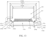
- FIG. 13 is a front sectional view illustrating the camera connector attached to an accessory shoe according to the second embodiment.
- FIG. 14 A is a bottom perspective view of an external flash unit according to a third embodiment of the present invention.
- FIG. 14 B is a sectional view of the external flash unit according to the third embodiment.
- FIG. 15 A is a perspective view illustrating an internal structure of a camera connector according to the third embodiment.
- FIG. 15 B is a front view illustrating the internal structure of the camera connector according to the third embodiment.
- FIG. 16 A is a rear perspective view of a digital camera and the external flash unit according to the third embodiment.
- FIG. 16 B is a sectional view illustrating a state in the middle of an insertion between a camera connector and an engagement member according to the third embodiment.
- FIG. 16 C is a sectional view illustrating an insertion completed state between the camera connector and the engagement member according to the third embodiment.
- an imaging system that includes a digital camera (image pickup apparatus) as an example of an electronic apparatus equipped with an accessory shoe apparatus, and an external flash unit (illumination apparatus) as an example of an accessory equipped with a shoe apparatus attachable to and detachable from the accessory shoe apparatus of the digital camera.
- the accessory provided with the shoe apparatus is not limited to the flash unit, but includes a variety of accessories such as an electronic viewfinder unit, a motion image capturing microphone, a conversion adapter, a variety of measurement apparatuses, and a sub camera.
- the electronic apparatus provided with the accessory shoe apparatus also includes a variety of electronic apparatuses other than the image pickup apparatus.
- FIG. 1 illustrates a configuration of a digital camera (simply referred to as a camera hereinafter) 100 .
- the camera 100 includes a camera MPU 101 as a microcomputer, an imaging optical system 122 , a timing signal generation circuit 102 , an image sensor 103 , an A/D converter 104 , a memory controller 105 , and a buffer memory 106 .
- the camera 100 further includes an image display unit 107 , a storage medium I/F 108 , a motor controller 110 , a shutter controller 111 , a photometric unit 112 , a multi-division photometric sensor 113 , a lens controller 114 , a focus detector 115 , an orientation detector 116 , and a switch operation unit 117 .
- the camera 100 further includes a flash controller 118 , a built-in flash 119 , a camera LED auxiliary light unit 121 , and an accessory shoe apparatus (simply referred to as an accessory shoe hereinafter) 123 .
- An external flash unit 120 as an accessory is attached to the accessory shoe 123 .
- a storage medium 109 such as a semiconductor memory, is attachable to and detachable from the camera 100 .
- the camera MPU 101 controls the entire imaging sequence of the camera 100 and the entire imaging system.
- the imaging optical system 122 has a plurality of lens units, such as a zoom lens and a focus lens, a diaphragm, a shutter, and the like, and forms an optical image (object image) of light from the field on the image sensor 103 .
- the image sensor 103 is an image sensor, such as a CCD sensor or a CMOS sensor, that captures (photoelectrically converts) an optical image.
- the timing signal generation circuit 102 generates a timing signal necessary to operate the image sensor 103 .
- the A/D converter 104 converts an analog signal read out of the image sensor 103 into a digital signal (image data).
- the memory controller 105 controls reading and writing of an unillustrated memory, a refresh operation of the buffer memory 106 , and the like.
- the buffer memory 106 temporarily stores the image data output from the A/D converter 104 and the display image data for displaying the image on the image display unit 107 .
- the image display unit 107 has a display device, such as a liquid crystal panel or an organic EL panel, and displays image data stored in the buffer memory 106 .
- the storage medium I/F 108 is an interface that enables communications between the attached storage medium 109 and the camera MPU 101 .
- Another storage medium such as a hard disk or an optical disk, may be built in the camera 100 .
- the motor controller 110 controls an unillustrated motor in accordance with a signal from the camera MPU 101 to move up and down an unillustrated mirror and charge the shutter.
- the shutter controller 111 controls the exposure of the image sensor 103 by running the front curtain and the rear curtain of the shutter in accordance with the signal from the camera MPU 101 .
- the multi-division photometric sensor 113 measures the luminance of each of a plurality of divided areas in an imaging screen.
- the photometric unit 112 outputs a luminance signal indicating the luminance of each area to the camera MPU 101 .
- the camera MPU 101 calculates AV (aperture value) for an exposure adjustment, TV (shutter speed), ISO (sensitivity of the image sensor 103 ), etc. based on the luminance signal acquired from the photometric unit 112 .
- the photometric unit 112 outputs to the camera MPU 101 the luminance signal when the built-in flash 119 or the external flash unit 120 makes a preliminary light emission (pre-light emission) toward the field, and calculates a light emission amount (main light emission amount) of the external flash unit 120 during the main imaging (pre-light emission).
- the lens controller 114 communicates with the camera MPU 101 via an unillustrated mount contact, and controls the focus and aperture value of the imaging optical system 122 through controls of an unillustrated lens drive motor and an unillustrated diaphragm drive motor.
- the focus detector 115 detects a defocus amount of the imaging optical system 122 using a focus detection method such as a phase difference detection method.
- the camera MPU 101 calculates a driving amount of the focus lens based on the detected defocus amount, and controls the lens drive motor through the lens controller 114 for autofocusing (AF).
- the orientation detector 116 detects a tilt of the camera 100 in the rotation direction around the optical axis of the imaging optical system 122 .
- the switch operation unit 117 includes a first switch (SW 1 ) that is turned on by a first stroke operation (half press) of an unillustrated release button, and a second switch (SW 2 ) that is turned on by a second stroke operation (full press) of the release button, and outputs an ON signal from each of them to the camera MPU 101 .
- the camera MPU 101 starts an imaging preparation operation such as AF and photometry in response to the ON signal from SW 1 , and starts an imaging (exposure) operation in response to the ON signal from SW 2 .
- the switch operation unit 117 also outputs a signal corresponding to the operation of an unillustrated operation member other than SW 1 and SW 2 to the camera MPU 101 .
- the flash controller 118 controls the light emission (pre-light emission, main light emission, auxiliary light emission, etc.) of the built-in flash 119 and the external flash unit 120 mounted on the accessory shoe 123 according to the instruction from the camera MPU 101 .
- the flash controller 118 detects that the external flash unit 120 is attached to the accessory shoe 123 , the flash controller 118 starts supplying the power to the external flash unit 120 via the accessory shoe 123 .
- the detailed configuration of the accessory shoe 123 will be described later.
- the camera LED auxiliary light unit 121 irradiates onto the field near-infrared light (LED auxiliary light) with a predetermined pattern used as auxiliary light for the focus detection by the focus detector 115 .
- the camera MPU 101 controls the light emission of auxiliary light by the built-in flash 119 or the external flash unit 120 for focus detection based on the luminance signal from the photometric unit 112 . More specifically, the camera MPU 101 instructs the built-in flash 119 or the external flash unit 120 to emit the auxiliary light via the flash controller 118 .
- the camera MPU 101 can also instruct the camera LED auxiliary light unit 121 or the LED auxiliary light unit 207 of the external flash unit 120 illustrated in FIG. 2 to emit the LED auxiliary light via the flash controller 118 .
- FIG. 2 illustrates the configuration of the external flash unit 120 .
- the external flash unit 120 includes a main body 200 , a bounce mechanical unit 201 , and a head unit 202 .
- the main body 200 includes an external flash MPU 203 , a main capacitor 209 , a variety of operation units 205 including a power switch, a display unit 208 , an LED auxiliary light unit 207 , and a camera connector 206 .
- the external flash MPU 203 is mounted on an unillustrated main board and controls all operations including the light emission control sequence of the external flash unit 120 .
- the camera connector 206 is a shoe apparatus that mechanically and electrically connects the external flash unit 120 to the accessory shoe 123 of the camera 100 .
- the camera MPU 101 and the external flash MPU 203 communicate with each other via the flash controller 118 , the accessory shoe 123 , and the camera connector 206 .
- the detailed configuration of the camera connector 206 will be described later.
- the LED auxiliary light unit 207 irradiates onto the field the LED auxiliary light such as near-infrared light having a predetermined pattern as the auxiliary light during the focus detection by the focus detector 115 in accordance with the camera MPU 101 .
- the bounce mechanical unit 201 is a mechanism for rotating the head unit 202 in the horizontal direction or the vertical direction relative to the main body 200 to change the light emitting direction of the illumination light (flash) from the head unit 202 . Use of the bounce mechanical unit 201 can indirectly illuminate the object and perform imaging (bounce imaging).
- the head unit 202 has a light emitter 204 that emits a flash of light.
- the light emitter 204 includes a light emitting discharge tube (xenon tube or the like), a light source such as an LED, a reflector, a Fresnel lens, and a light emission circuit.
- the light emission circuit causes the light source to emit a flash of light according to a signal from the external flash MPU 203 .
- FIG. 3 A illustrates the camera 100 viewed from the diagonally rear side.
- FIG. 3 B illustrates how to attach the external flash unit 120 to the accessory shoe 123 of the camera 100 .
- FIG. 3 C illustrates the external flash unit 120 attached to the camera 100 when viewed from the oblique rear side.
- the imaging optical system 122 illustrated in FIG. 1 is provided on the front side (field side) of the camera 100 , and the image display unit 107 is provided on the rear side of the camera 100 .
- a top cover 150 as an exterior member is provided on the top surface of the camera 100 , and an accessory shoe 123 is provided to the top cover 150 .
- the camera connector 206 is provided at the bottom of the external flash unit 120 .
- the external flash unit 120 is slid in a direction parallel to the front side in the Z direction (corresponding to the attachment side in the first direction and the front side in the attachment direction) relative to the camera 100 to engage the camera connector 206 and the accessory shoe 123 with each other. Thereby, the external flash unit 120 can be attached to the camera 100 .
- the front side in the Z direction is a direction from the rear side to the front side of the camera 100 , that is, a direction from the image display unit 107 side toward the imaging optical system 122 side.
- An X direction (second direction), a Y direction (third direction), and the Z direction (front-back direction) illustrated in FIGS. 4 A and 4 B and subsequent figures are commonly used.
- the X direction is a direction orthogonal to the Z direction in the horizontal plane when the Z direction is parallel to the horizontal direction, and is the width direction of the camera 100 .
- the Y direction is a direction orthogonal to the Z direction and the X direction, and is the height direction of the camera 100 .
- FIG. 4 A illustrates the top cover 150 and the exploded accessory shoe 123 .
- FIG. 4 B illustrates the assembled accessory shoe 123 .
- the assembly direction of the accessory shoe 123 onto the top cover 150 is the Y direction.
- the accessory shoe 123 includes an engagement member 151 , a connection terminal connector 152 , a shoe stage 153 , and an accessory shoe spring 154 .
- the engagement member 151 is a member for holding the external flash unit 120 through an engagement with the external flash unit 120 .
- the connection terminal connector 152 includes a plurality of connection terminals 152 a arranged at regular pitches in the X direction on a connector base member 152 e as a holding member made of a resin material or the like and held by the connector base member 152 e .
- the connection terminals 152 a are arranged on the front side in the Z direction as the attachment direction of the external flash unit 120 (on the front side of the camera 100 ) as illustrated in FIG. 4 B .
- An engagement hole portion 156 to be engaged with a lock pin 252 of the external flash unit 120 illustrated in FIG. 6 A is provided behind the connection terminal connector 152 in the Z direction (on the rear side of the digital camera 100 ).
- connection terminals 152 a are electrically connected to the external flash unit 120 .
- Each of the plurality of connection terminals 152 a is electrically connected to a flexible substrate 158 disposed on the lower side of the top cover 150 in the Y direction.
- the flexible substrate 158 is connected to an unillustrated main substrate of the camera 100 .
- the shoe stage 153 is a housing member that encloses the engagement member 151 and the connection terminal connector 152 .
- An accessory shoe holding member 155 is a structural skeleton that holds the engagement member 151 .
- the accessory shoe holding member 155 , the flexible substrate 158 , the top cover 150 , the shoe stage 153 , and the connection terminal connector 152 are fastened to the engagement member 151 by four screws 157 that are inserted into them. Thereby, these members are mutually positioned and fixed.
- the four screws 157 one by one in four areas equally divided in the X direction and the Z direction, the above components can be connected in a well-balanced manner.
- FIG. 5 A illustrates the structure on the top surface side of the engagement member 151
- FIG. 5 B illustrates the structure on the bottom surface side of the engagement member 151
- FIG. 5 C illustrates the structure of the connection terminal connector 152 on the top surface side
- FIG. 11 illustrates the accessory shoe 123 viewed from the insertion direction of the external flash unit 120 .
- the engagement member 151 is formed by bending a metal plate in a loop shape so that the end surfaces of the bent ends face and contact each other at a seam 151 a .
- the engagement member 151 has a pair of engagement portions 151 b , and a coupler 151 c that couples the pair of engagement portions 151 b together.
- the engagement member 151 has a pair of first screw hole portions 151 d used for fastening the screws 157 and a pair of second screw hole portions 151 e .
- the engagement member 151 has engagement hole portions 156 to be engaged with the lock pins 252 of the external flash unit 120 .
- the pair of engagement portions 151 b are separated by a first width (referred to as engagement portion interval hereinafter) 151 aa in the X direction.
- a holding member 254 of the external flash unit 120 which will be described later, illustrated in FIG. 6 B is inserted into the engagement portion interval 151 aa .
- the pair of first screw hole portions 151 d are provided at a predetermined interval in the X direction, and serve as a pair of first fastening hole portions provided apart from each other in the X direction at the back (on the rear side) in the Z direction.
- the pair of second screw hole portions 151 e are provided at a predetermined interval in the X direction, and serve as a pair of second fastening hole portions provided apart from each other in the X direction at the front in the Z direction.
- the engagement hole portion 156 is formed at a position engageable with the lock pin 252 of the external flash unit 120 in an area sandwiched between the pair of first screw hole portions 151 d.
- connection terminal connector 152 As illustrated in FIGS. 4 B and 5 C , a plurality of connection terminals 152 a are exposed.
- the position of the camera connector 206 In the pitch direction (X direction) in which the plurality of connection terminals 152 a are aligned, the position of the camera connector 206 is determined by the engagement portion interval 151 aa of the engagement member 151 . Therefore, the holding member 254 of the external flash unit 120 is positioned relative to the connection terminal connector 152 by the engagement member 151 .
- connection terminal connector 152 (connector base member 152 e ) sandwiching the plurality of connection terminals 152 a in the X direction on the front side in the Z direction, there are formed contact surfaces 152 b that contact and position the accessory shoe 123 in the Z direction when the external flash unit 120 is attached, and groove portions 152 c into which the accessory shoe 123 is inserted.
- Each groove portion 152 c is formed so as to extend from the contact surface 152 b to the front side (attachment side) in the Z direction, and has a slope portion 152 d so as to face inwardly and diagonally upwardly (so as to have a tilt to the X direction).
- Part of the groove portion 152 c above the slope portion 152 d extends outwardly in the X direction from the position of the top end of the slope portion 152 d . This is to prevent a dent (sink) from being generated in the slope portion 152 d during resin molding if the slope portion 152 d is formed up to the top end of the groove portion 152 c.
- an outermost inner surface 152 ccc of the groove portion 152 c in the connector base member 152 e of the accessory shoe 123 is located outside of the inner end surfaces of the pair of engagement portions 151 b of the engagement member 151 (engagement portion interval 151 aa ) and is located inside of the outermost inner surface 151 bb of the engagement member 151 .
- a slope start position 152 cc which is the end (lower end) of the slope portion 152 d on the bottom surface side of the groove portion 152 c , is provided inside the engagement portion interval 151 aa . Thereby, it is possible to secure an area for providing the contact surface 152 b that comes into contact with a contact portion 251 b described later of the camera connector 206 and positions it in the Z direction.
- Providing the slope shape starting from the slope start position 152 cc can expand a space into which the shoe apparatus (camera connector 206 described later) of the external flash unit 120 is inserted, and can secure the degree of freedom in the shape of the shoe apparatus. As a result, the shoe apparatus of the external flash unit 120 can be sufficiently formed with a shape that protects the connection terminals.
- FIG. 6 A illustrates the external flash unit 120 viewed from the camera connector 206 side (bottom side in the Y direction).
- FIG. 6 B is a section taken along a line A-A in FIG. 6 A and illustrates the internal structure of the camera connector 206 .
- FIG. 7 A illustrates the camera connector 206 . However, a base portion 250 and a lock lever 253 , which will be described later, are omitted.
- FIG. 7 B illustrates the camera connector 206 viewed from the front in the Z direction.
- the camera connector 206 is provided on the bottom side in the Y direction (top side in FIG. 6 A ) of the base portion 250 of the external flash unit 120 as illustrated in FIG. 6 B when it is attached to the accessory shoe 123 of the camera 100 .
- the camera connector 206 includes a shoe attachment leg (engagement member, shoe plate) 251 , the lock pins 252 , a lock lever 253 , a holding member 254 , a connection plug 256 , and a Y-direction holding member 258 .
- the shoe attachment leg 251 is an engagement member that engages the external flash unit 120 with the accessory shoe 123 of the camera 100 and holds it. That is, the shoe attachment leg 251 is an engagement member on the external flash unit 120 side attachable to and detachable from the engagement member 151 of the accessory shoe 123 .
- the shoe attachment leg 251 is manufactured by processing a metal plate (sheet metal) in order to secure a high mechanical strength against such a large stress.
- the lock pin 252 is a member for preventing the external flash unit 120 from falling off while the camera connector 206 (shoe attachment leg 251 ) is attached to the accessory shoe 123 , and is held on the shoe attachment leg 251 movable in the Y direction. More specifically, the lock pin 252 is slidably held in the Y direction by the Y-direction holding member 258 . The lock lever 253 and the Y-direction holding member 258 are held by the holding member 254 .
- the Y-direction holding member 258 is moved downwardly in the Y-direction in FIG. 6 B by an unillustrated cam portion.
- the lock pin 252 also moves downwardly in the Y direction in FIG. 6 B together with the Y-direction holding member 258 .
- the lock pin 252 projects from the shoe attachment leg 251 and is engaged with the engagement hole portion 156 provided in the engagement member 151 of the accessory shoe 123 .
- the lock pin 252 and the engagement hole portion 156 serve as a positioning member in the Z direction for ensuring an electrical connection between the external flash unit 120 and the camera 100 .
- connection plug 256 as a connector is provided on the front side in the Z direction of the camera connector 206 , made of a nonconductive material (dielectric material) such as a resin material, and integrated with the holding member 254 .
- An outermost width T of the connection plug 256 in the X direction is narrower than a width W of the shoe attachment leg 251 in the X direction. Thereby, an area for providing the contact portion 251 b on the shoe attachment leg 251 is secured.
- the connection plug 256 has a plurality of connection terminals 257 for contacting and communicating with the plurality of connection terminals 152 a of the accessory shoe 123 illustrated in FIG. 5 C .
- connection terminals 257 are provided so as to have a one-to-one correspondence with the plurality of connection terminals 152 a , and held by the holding member 254 so as to extend in the Z direction and to line up in the X direction.
- Each connection terminal 257 has a tip portion 257 a that comes into contact with the corresponding connection terminal 152 a .
- Each connection terminal 257 has a shape extending backwardly in the Z direction from a tip portion 257 a , and has an extension portion 257 b that displaces the tip portion 257 a upwardly in the Y direction in FIG. 6 B by an elastic deformation when the tip portion 257 a comes into contact with the connection terminal 152 a .
- a vertical extension portion 257 c extending upwardly in the Y direction is formed at the back end of the extension portion 257 b in the Z direction.
- a flexible substrate connector 257 d Provided at the upper end of the vertical extension portion 257 c is a flexible substrate connector 257 d to be connected to an unillustrated main substrate of the external flash unit 120 and connected to a flexible substrate 259 inserted into the holding member 254 from the top side in the Y direction.
- the extension portion 257 b has a step portion 257 e having a step in the Y direction in the middle of the Z direction.
- the extension portion 257 b can be elastically deformed in the Y direction.
- a sufficient deformation amount cannot be obtained, and the durability is lowered.
- the connection terminal 152 a and the tip portion 257 a are repeatedly attached and detached, and the extension portion 257 b may easily get damaged. Accordingly, providing the step portion 257 e to the extension portion 257 b can secure a sufficient distance L without causing the extension portion 257 b to interfere with the shoe attachment leg 251 .
- each protrusion portion 256 a protrudes below a line made by connecting the lower ends of the tip portions 257 a of the connection terminals 257 in order to protect the connection terminals 257 from external forces such as the pressure and the impact. That is, the tip portions 257 a of the connection terminals 257 is provided above (inside) a line made by connecting the lower tip portions 256 d of the pair of protrusion portions 256 a.
- each protrusion portion 256 a is provided with the slope portion 256 b on a side that does not face the plurality of connection terminals 257 so that a width of each protrusion portion 256 a in the X direction is smaller at a position of the tip in the Y direction than at a position away from the tip. Since each protrusion portion 256 a has such a shape, the connection plug 256 can be inserted into the groove portion 152 c having the slope portion 152 d in the connection terminal connector 152 .
- the slope portion 256 b has a role of releasing an external force, such as the pressure and impact, from the connection plug 256 to prevent the connection plug from getting damaged.
- FIG. 7 C illustrates that an external force is applied to the connection plug 256 from the X direction.
- FIG. 7 C illustrates the connection plug 256 viewed from the front in the Z direction.
- An external force from the X direction is defined as F 1 as a vector.
- the external force F 1 acting on the slope portion 256 b is decomposed according to the addition theorem in the vector space into a component force F 2 in a direction along the slope portion 256 b and a component force F 3 in a direction perpendicular to the slope portion 256 b .
- ⁇ is an angle formed by the external force F 1 and the slope portion 256 b
- the component force F 2 and the component force F 3 can be calculated by the following expression (1).
- ⁇ 0° ⁇ 90°. In this range, the following is established:
- the component force F 3 is the only force that affects the connection plug 256 . As described above, since the component force F 3 is smaller than the component force F 1 , the connection plug 256 can be prevented from getting damaged even if an external force that is large to some extent is applied.
- FIG. 12 illustrates the partially enlarged connection plug 256 viewed from the Z direction.
- B is a height from the lower tip portion 256 d of the protrusion portion 256 a to the top surface of the connection plug 256 (a height of the connection plug including the protrusion portion)
- A is a height of the slope portion 256 b from the lower tip portion 256 d (slope start position 256 c ) to the upper end of the slope portion 256 b .
- A is preferably one-fifth or more of B, more preferably one-fourth or more, one-third or more, or half or more as illustrated in FIG. 12 .
- the slope portion 256 b is formed to have a significant size for the function of releasing the external force from the X direction, and is different from a chamfered shape generally provided at the corner of the protrusion portion.
- the tilt angle ⁇ of the slope portion 256 b to the X direction is preferably set in a range of 45° ⁇ 20° for the above function of releasing the external force.
- the contact portion which is a portion that comes into contact with the contact surface 152 b of the accessory shoe 123 and is provided at a position between a shoe engagement portion 251 a and the protrusion portion 256 a in the X direction, has a different width in the X direction in an area that contacts the contact surface 152 b , depending on a position in the Y direction.
- a position closer to the tip of the protrusion portion 256 a in the Y direction has a wider width in the X direction in the area that contacts the contact surface 152 b .
- the lower tip portion 256 d which is the lower end in the Y direction of the tip portion in the Z direction, is not provided at a position that is below the plurality of connection terminals 257 in the Y direction and outside of the end of the shoe engagement portion 251 a on the side of the plurality of connection terminals 257 in the X direction.
- the lower tip portion 256 d is provided at a position lower than the plurality of connection terminals 257 in the Y direction.
- the lower tip portion 256 d is provided at a position inside the end of the shoe engagement portion 251 a on the side of the plurality of connection terminals 257 in the X direction. This configuration can secure a sufficient area of the contact portion 251 b.
- the camera connector 206 has such a structure that the shoe attachment leg 251 and the holding member 254 are fastened. The details of this fastening structure will be described later.
- the holding member 254 can be inserted into the engagement portion interval 151 aa of the engagement member 151 of the accessory shoe 123 illustrated in FIG. 5 A , and has a coupler 254 a having a width V shorter than the width W of the shoe attachment leg 251 in the X direction.
- the widths W and V are defined by the Japanese Industrial Standards (JIS) B7101-1975 “camera accessory attachment seat and attachment foot.”
- the position of the external flash unit 120 relative to the camera 100 is determined in the Z direction.
- the holding member 254 is also a structure for coupling the shoe attachment leg 251 and the base portion 250 , and the lock pins 252 and the connection terminals 257 are arranged inside the coupler 254 a.
- FIG. 8 A illustrates the camera connector 206 viewed from the upper side in the Y direction
- FIG. 8 B illustrates a section taken along a line B-B in FIG. 8 A .
- a pair of first screw 260 a and a pair of second screws 260 b which are fastening members for fastening the shoe attachment leg 251 to the holding member 254 , penetrate the holding member 254 and are fastened to the shoe attachment leg 251 .
- the shoe attachment leg 251 is stably held by the holding member 254 .
- the shoe attachment leg 251 is a component to which a large stress is applicable. Therefore, a required mechanical strength can be ensured by fastening the metal shoe attachment legs 251 to the holding member 254 with a pair of first screws 260 a and a pair of second screws 260 b arranged in a well-balanced manner.
- connection terminals 257 are arranged in an area S sandwiched by the pair of first screws 260 a and the pair of second screws 260 b .
- the widths between the pair of first screws 260 a and between the pair of second screws 260 b are narrower than the width between the lower tip portions 256 d of the protrusion portions 256 a of the connection plug 256 , the width V of the holding member 254 , the outermost width T of the connection plug 256 , and the width W of the shoe attachment leg 251 .
- FIG. 13 illustrates a section of the accessory shoe 123 viewed from the Z direction while the camera connector 206 is attached to the accessory shoe 123 .
- This figure illustrates the sizes T and V of the camera connector 206 and the positional relationship between each component of the camera connector 206 and each component of the accessory shoe 123 .
- the top surface of the shoe engagement portion 251 a of the camera connector 206 contacts the bottom (ceiling surface) of the engagement member 151 of the accessory shoe 123 for positioning in the Y direction.
- the lower tip portion 256 d of the protrusion portion 256 a can come into contact with the bottom surface of the groove portion 152 c of the accessory shoe 123 , and a floating amount of the connection plug 256 (a tilt to the accessory shoe 123 ) can be reduced.
- Each of a gap between the slope portions 256 b and 152 d and a gap between the inner end surface 152 ccc of the groove portion 152 c and the outer end surface of the connection plug 256 is set to be large to some extent. Thereby, when an external force in the X direction is applied to the external flash unit 120 , the connection terminals 257 and 152 a can be prevented from getting loaded.
- a relationship between a height of the groove portion 152 c in the Y direction (a height from the bottom surface of the groove portion 152 c to a ceiling surface of the engagement member 151 ) and a height of the slope portion 152 d in the Y direction is similar to a relationship between the height B of the connection plug 256 and the height A of the slope portion 256 b in the camera connector 206 .
- the tilt angle of the slope portion 256 b to the X direction is also set in the range of 45° ⁇ 20°, similarly to the tilt angle ⁇ of the slope portion 256 b in the camera connector 206 .
- each embodiment described above has described a surface shape of the slope portion 256 b provided on the protrusion portion 256 a being flat, but the slope portion 256 b may be a curved surface having a curvature. That is, the slope portion 256 b may have a surface with a tilt to the X direction.
- This embodiment can secure an area for providing a larger number of connection terminals than ever and a shape for protecting them and an area for positioning between components, in the compact camera connector 206 and accessory shoe 123 .
- FIG. 9 A illustrates the external flash unit 120 viewed from the camera connector 206 side (lower side in the Y direction).
- FIG. 9 B illustrates a section taken along a line A-A in FIG. 9 A and illustrates the internal structure of the camera connector 206 .
- FIG. 10 A illustrates the camera connector 206 . However, the base portion 250 and the lock lever 253 are omitted.
- FIG. 10 B illustrates the camera connector 206 viewed from the front in the Z direction.
- the camera connector 206 is provided on the lower side in the Y direction (upper side in FIG. 9 A ) of the base portion 250 of the external flash unit 120 as illustrated in FIG. 9 B while it is attached to the accessory shoe 123 of the camera 100 .
- the camera connector 206 has a shoe attachment leg 300 a , lock pins 252 , a lock lever 253 , a holding member 300 , a connection plug 300 b , a Y-direction holding member 258 , and a shoe cover 301 .
- the shoe attachment leg 300 a is an engagement member for engaging the external flash unit 120 with the accessory shoe 123 of the camera 100 , similar to the shoe attachment leg 251 of the first embodiment. That is, the shoe attachment leg 300 a is an engagement member on the external flash unit 120 side attachable to and detachable from the engagement member 151 of the accessory shoe 123 .
- the shoe attachment leg 251 as a metal shoe plate and the resin holding member 254 are formed as separate members in order to give priority to the mechanical strength.
- the shoe attachment leg 300 a and the holding member 300 are formed as an integrated member by a resin material (nonconductive material).
- the pair of first screws 260 a and the pair of second screws 260 b described in the first embodiment are not required, a space for arranging the connection terminals 257 becomes wider, and thus a larger number of connection terminals 257 than that of the first embodiment can be arranged.
- the external flash unit 120 can communicate more information with the camera 100 via the camera connector 206 and the accessory shoe 123 .
- connection plug 300 b is provided on the front side in the Z direction of the camera connector 206 , and formed as an integrated member with the holding member 300 made of a nonconductive resin material in this embodiment. Similar to the first embodiment, the outermost width T of the connection plug 300 b in the X direction is made narrower than the width W of the shoe attachment leg 300 a in the X direction, so that the area for providing the contact portion 300 e is secured in the shoe attachment leg 300 a .
- the connection plug 300 b has a plurality of connection terminals 257 for contacting and communicating with the plurality of connection terminals 152 a of the accessory shoe 123 illustrated in FIG. 5 C .
- the shoe cover 301 is an enclosure attached to the holding member 300 , and is a member that protects a plurality of connection terminals 257 .
- the shape of the connection terminal 257 is similar to that of the first embodiment, and the step portion 257 e is provided to secure a sufficient distance L in the Z direction of the extension portion 257 b without interfering with the shoe cover 301 .
- connection plug 300 b is also similar to that of the connection plug 256 of the first embodiment, and a pair of protrusion portions 300 c that project downwardly in the Y direction are provided so as to sandwich the plurality of connection terminals 257 at both ends of the connection plug 300 b in the X direction.
- a lower tip portion 300 k of each protrusion portion 300 c projects below a line made by connecting the lower ends of the tip portions 257 a of the connection terminals 257 in order to protect the connection terminal 257 from the external force such as the pressure and the impact. That is, the tip portion 257 a of the connection terminal 257 is provided above (inside) a line made by connecting the lower tip portions 300 k of the pair of protrusion portions 300 c.
- each protrusion portion 300 c in the X direction is a slope portion 300 f that extends diagonally upwardly from the lower tip portion 300 k and faces diagonally downwardly.
- Each protrusion portion 300 c having such a shape enables the connection plug 300 b to be inserted into the groove portion 152 c having the slope portion 152 d in the connection terminal connector 152 described in the first embodiment.
- the slope portion 300 f has a role of releasing the external force such as the pressure and the impact on the connection plug 300 b to prevent the connection plug from getting damaged.
- the slope start positions 300 g on both sides are provided inside the width V of the holding member 254 in the X direction to sufficiently secure the area of the contact portion 300 e of the shoe attachment leg 300 a.
- the holding member 300 is formed so that it can be inserted into the engagement portion interval 151 aa of the engagement member 151 illustrated in FIG. 5 A and engaged with the engagement member 151 , and has a coupler 300 h having a width V shorter than the width W of the shoe attachment leg 300 a in the X direction.
- the width W and the width V are defined by the Japanese Industrial Standards (JIS) B7101-1975 “camera accessory attachment seat and attachment foot” as in the first embodiment.
- the shoe attachment leg 300 a is urged upwardly in the Y direction when it contacts the elastic deformer 154 a of the accessory shoe spring 154 illustrated in FIGS. 4 A and 4 B , and thereby the top surface of the shoe engagement portion 300 d contacts the bottom surface of the engagement member 151 . Thereby, the position of the external flash unit 120 relative to the camera 100 is determined in the Y direction.
- the position of the external flash unit 120 relative to the camera 100 is determined in the Z direction.
- the holding member 300 is also a structure for coupling the shoe attachment legs 300 a and the base portion 250 , and the lock pin 252 and the connection terminal 257 are arranged inside the coupler 300 h.
- FIG. 14 A illustrates the external flash unit 120 viewed from the camera connector 206 side (lower side in the Y direction).
- FIG. 14 B illustrates a section taken along a line A-A in FIG. 14 A and illustrates the internal structure of the camera connector 206 .
- FIG. 15 A illustrates the camera connector 206 . However, the base portion 250 and the lock lever 253 are omitted.
- FIG. 15 B illustrates the camera connector 206 viewed from the front in the Z direction.
- FIG. 16 A illustrates the external flash unit 120 attached to the camera 100 viewed from the diagonally rear side.
- FIG. 16 B illustrates a section taken along a line B-B in FIG. 16 A , which shows a state in the middle of an insertion of the camera connector 206 (shoe attachment leg 400 a ) of the external flash unit 120 into the accessory shoe 123 (engagement member 151 ) of the camera 100 .
- FIG. 16 C illustrates the same section as that of FIG. 16 B , which shows an insertion completed state of the shoe attachment leg 400 a into the accessory shoe 123 and a holding state of the shoe attachment leg 400 a by the accessory shoe 123 .
- the shoe attachment leg 400 a is an engagement member for engaging the external flash unit 120 with the accessory shoe 123 of the camera 100 , similar to the shoe attachment leg 251 of the first embodiment. That is, the shoe attachment leg 400 a is an engagement member on the external flash unit 120 side that can be attached to and detached from the engagement member 151 of the accessory shoe 123 .
- the shoe attachment leg 400 a and the holding member 400 are formed as an integrated member by a resin material (nonconductive material), similar to the shoe attachment leg 300 a and the holding member 300 of the second embodiment.
- a resin material nonconductive material
- the pair of first screws 260 a and the pair of second screws 260 b described in the first embodiment are not required, and the space for arranging the connection terminals 257 becomes wider, so that a larger number of connection terminals 257 can be arranged than that of the first embodiment.
- the external flash unit 120 can communicate more information with the camera 100 via the camera connector 206 and the accessory shoe 123 .
- connection plug 400 b is provided on the front side in the Z direction of the camera connector 206 , and is formed as an integrated member with the holding member 400 made of a nonconductive resin material as in the second embodiment. Similar to the first and second embodiments, when the outermost width T of the connection plug 400 b in the X direction is made narrower than the width W of the shoe attachment leg 400 a in the X direction, the area for providing the contact portion 400 e in the shoe attachment leg 400 a is secured.
- the connection plug 400 b includes a plurality of connection terminals 257 that contact and communicate with the plurality of connection terminals 152 a of the accessory shoe 123 illustrated in FIG. 5 C .
- the shoe cover 301 is an enclosure attached to the holding member 400 , and is a member that protects a plurality of connection terminals 257 .
- the shape of the connection terminal 257 is similar to that of each of the first and second embodiments, and the step portion 257 e is provided to secure a sufficient distance L in the Z direction of the extension portion 257 b without interfering with the shoe cover 301 .
- connection plug 400 b is also similar to that of the connection plug 256 of the first and second embodiments, and a pair of protrusion portions 400 c that protrude downwardly in the Y direction are provided on both sides of the pair of connection plugs 400 b in the X direction so as to sandwich the plurality of connection terminals 257 .
- the lower tip portion 400 k of each protrusion portion 400 c protrudes below a line made by connecting the lower ends of the tip portions 257 a of the connection terminals 257 in order to protect the connection terminal 257 from the external force such as the pressure and the impact. That is, the tip portions 257 a of the connection terminals 257 are provided above (inside) a line made by connecting the lower tip portions 400 k of the pair of protrusion portions 400 c.
- This embodiment also provides, outside each protrusion portion 400 c in the X direction, a slope portion 400 f that extends diagonally upwardly from the lower tip portion 400 k and faces diagonally downwardly.
- Each protrusion portion 400 c having such a shape enables the connection plug 400 b to be inserted into the groove portion 152 c having the slope portion 152 d in the connection terminal connector 152 described in the first embodiment.
- the slope portion 400 f has a role of releasing the external force such as the pressure and the impact on the connection plug 400 b to prevent the connection plug from getting damaged.
- the slope start positions 400 g on both sides are provided inside the width V of the holding member 254 in the X direction to sufficiently secure an area for the contact portion 400 e of the shoe attachment leg 400 a.
- the holding member 400 is formed so that it can be inserted into the engagement portion interval 151 aa of the engagement member 151 illustrated in FIG. 5 A and can be engaged with the engagement member 151 , and has a connector 400 h having the width V shorter than the width W of the shoe attachment leg 400 a in the X direction.
- the width W and the width V are defined by the Japanese Industrial Standards (JIS) B7101-1975 “camera accessory attachment seat and attachment foot” as in the first and second embodiments.
- the holding member 400 is also a structure for coupling the shoe attachment leg 400 a and the base portion 250 , and the lock pin 252 and the connection terminal 257 are arranged inside the connector 400 h.
- the shoe attachment leg 400 a has a contact area (first area) 400 j that contacts the elastic deformer 154 a of the accessory shoe spring 154 illustrated in FIGS. 4 A and 4 B .
- the contact area 400 j contacts the elastic deformer 154 a of the accessory shoe spring 154
- the shoe attachment leg 400 a is urged upwardly in the Y direction, and the top surface of the shoe engagement portion 400 d comes into contact with the bottom surface of the engagement member 151 .
- An arrow F in FIGS. 16 B and 16 C represents the urging force of the accessory shoe spring 154 .
- the position of the external flash unit 120 with respect to the camera 100 is determined in the Y direction.
- the contact area 400 j corresponds to the urging area urged by the elastic deformer 154 a of the accessory shoe spring 154 in the middle of an insertion and in the insertion completed state of the external flash unit 120 into the accessory shoe 123 .
- a contact area 400 j is disposed on both sides of the plurality of connection terminals 152 a on the front side (front side of the camera 100 ) in the Z direction as the attachment direction.
- the shoe attachment leg 400 a has a noncontact area (second area) 400 i that does not contact the elastic deformer 154 a of the accessory shoe spring 154 .
- This noncontact area 400 i corresponds to a non-urged area that is not urged by the elastic deformer 154 a of the accessory shoe spring 154 in the middle of the insertion and in the insertion completed state of the external flash unit 120 into the accessory shoe 123 .
- FIG. 16 C since a gap is formed between the accessory shoe spring 154 and the noncontact area 400 i , the urging force by the accessory shoe spring 154 against the noncontact area 400 i is 0.
- This embodiment sets the thickness of the noncontact area 400 i in the Y direction to be larger than the thickness of the contact area 400 j in the same direction.
- the thickness of the contact area 400 j is set to be the same as that of the first and second embodiments.
- the thickness of the noncontact area 400 i in the Y direction is made larger than the contact area 400 j for the following reasons.
- the resin shoe in this embodiment is inferior in strength to the metal shoe of the first embodiment when they are compared with each other in the same shape. Therefore, the strength can be ensured by increasing the thickness of the shoe attachment leg 400 a in the non-contact area 400 i in the Y direction.
- the strength calculated by the moment of inertia of area increases in proportion to the square of the thickness, the strength can be efficiently improved by increasing the thickness in the Y direction.
- the shoe attachment leg 400 a is made versatile according to the JIS, and the elastic deformer 154 a of the accessory shoe spring 154 can be prevented from plastically deforming beyond the yield point.
- the thickness of the contact area 400 j in the Y direction is made the same as that of each of the first and second embodiments.
- the elastic deformer 154 a can be prevented from plastically deforming beyond a yield point even in the middle of the attachment of the external flash unit 120 to the accessory shoe 123 .
- This embodiment sets the noncontact area 400 i to a non-urged area that is not urged by the elastic deformer 154 a of the accessory shoe spring 154 in the middle of the insertion and in the insertion completed state of the external flash unit 120 into the accessory shoe 123 .
- the noncontact area 400 i may be urged by the accessory shoe spring 154 in the middle of the insertion and in the insertion completed state of the external flash unit 120 into the accessory shoe 123 .
- the area in which the urging force by the accessory shoe spring 154 is smaller than the contact area 400 j may be set to the area corresponding to the noncontact area 400 i . That is, the thickness of the second area of the shoe attachment leg 400 a is larger than that of the first area, and the second area has a smaller urging force (including an urging force of zero) by the accessory shoe spring 154 than that of the first area.
- the position of the external flash unit 120 relative to the camera 100 is determined in the Z direction.
- Each of the above embodiments can secure, in the compact shoe apparatus and accessory shoe apparatus, an area for providing a larger number of connection terminals than ever and a shape for protecting them and an area for positioning between components.
- the present invention provides a compact shoe apparatus and accessory shoe apparatus, each of which can secure an area for providing a large number of connection terminals and a shape for protecting them, and a positioning area between components.
Landscapes
- Physics & Mathematics (AREA)
- General Physics & Mathematics (AREA)
- Engineering & Computer Science (AREA)
- Multimedia (AREA)
- Signal Processing (AREA)
- Accessories Of Cameras (AREA)
- Stroboscope Apparatuses (AREA)
- Studio Devices (AREA)
- Connector Housings Or Holding Contact Members (AREA)
- Coupling Device And Connection With Printed Circuit (AREA)
Priority Applications (1)
| Application Number | Priority Date | Filing Date | Title |
|---|---|---|---|
| US18/769,211 US20240377715A1 (en) | 2020-04-09 | 2024-07-10 | Shoe apparatus, accessory, accessory shoe apparatus, and electronic apparatus |
Applications Claiming Priority (5)
| Application Number | Priority Date | Filing Date | Title |
|---|---|---|---|
| JP2020-070625 | 2020-04-09 | ||
| JP2020070625 | 2020-04-09 | ||
| JP2020-148939 | 2020-09-04 | ||
| JP2020148939A JP7346371B2 (ja) | 2020-04-09 | 2020-09-04 | シュー装置、アクセサリ、アクセサリシュー装置および電子機器 |
| PCT/JP2021/014319 WO2021206018A1 (ja) | 2020-04-09 | 2021-04-02 | シュー装置、アクセサリ、アクセサリシュー装置および電子機器 |
Related Parent Applications (1)
| Application Number | Title | Priority Date | Filing Date |
|---|---|---|---|
| PCT/JP2021/014319 Continuation WO2021206018A1 (ja) | 2020-04-09 | 2021-04-02 | シュー装置、アクセサリ、アクセサリシュー装置および電子機器 |
Related Child Applications (1)
| Application Number | Title | Priority Date | Filing Date |
|---|---|---|---|
| US18/769,211 Division US20240377715A1 (en) | 2020-04-09 | 2024-07-10 | Shoe apparatus, accessory, accessory shoe apparatus, and electronic apparatus |
Publications (2)
| Publication Number | Publication Date |
|---|---|
| US20220082911A1 US20220082911A1 (en) | 2022-03-17 |
| US12066751B2 true US12066751B2 (en) | 2024-08-20 |
Family
ID=78079518
Family Applications (2)
| Application Number | Title | Priority Date | Filing Date |
|---|---|---|---|
| US17/533,815 Active 2041-12-12 US12066751B2 (en) | 2020-04-09 | 2021-11-23 | Shoe apparatus, accessory, accessory shoe apparatus, and electronic apparatus |
| US18/769,211 Pending US20240377715A1 (en) | 2020-04-09 | 2024-07-10 | Shoe apparatus, accessory, accessory shoe apparatus, and electronic apparatus |
Family Applications After (1)
| Application Number | Title | Priority Date | Filing Date |
|---|---|---|---|
| US18/769,211 Pending US20240377715A1 (en) | 2020-04-09 | 2024-07-10 | Shoe apparatus, accessory, accessory shoe apparatus, and electronic apparatus |
Country Status (8)
| Country | Link |
|---|---|
| US (2) | US12066751B2 (https=) |
| EP (1) | EP4024130A4 (https=) |
| JP (4) | JP7346371B2 (https=) |
| KR (1) | KR102669396B1 (https=) |
| CN (3) | CN117111381A (https=) |
| BR (1) | BR112021021830A2 (https=) |
| TW (1) | TWI837466B (https=) |
| WO (1) | WO2021206018A1 (https=) |
Families Citing this family (6)
| Publication number | Priority date | Publication date | Assignee | Title |
|---|---|---|---|---|
| JP7721301B2 (ja) | 2020-04-09 | 2025-08-12 | キヤノン株式会社 | 電子機器およびアクセサリ |
| JP7087152B2 (ja) | 2020-04-09 | 2022-06-20 | キヤノン株式会社 | 電子機器およびアクセサリ |
| JP7346371B2 (ja) * | 2020-04-09 | 2023-09-19 | キヤノン株式会社 | シュー装置、アクセサリ、アクセサリシュー装置および電子機器 |
| JP7721302B2 (ja) | 2020-04-09 | 2025-08-12 | キヤノン株式会社 | 電子機器およびアクセサリ |
| JP7743198B2 (ja) | 2020-04-09 | 2025-09-24 | キヤノン株式会社 | 電子機器およびアクセサリ |
| JP2021167944A (ja) | 2020-04-09 | 2021-10-21 | キヤノン株式会社 | 電子機器およびアクセサリ |
Citations (78)
| Publication number | Priority date | Publication date | Assignee | Title |
|---|---|---|---|---|
| US4449802A (en) | 1978-12-25 | 1984-05-22 | Canon Kabushiki Kaisha | Adapter device |
| US4887120A (en) | 1984-02-04 | 1989-12-12 | Ricoh Company, Ltd. | Electronic flash photographing system |
| US5384611A (en) | 1991-05-20 | 1995-01-24 | Minolta Camera Kabushiki Kaisha | Camera system capable of wireless flash photographing |
| JPH07234432A (ja) | 1994-05-09 | 1995-09-05 | Nikon Corp | レンズ及び補助装置及びカメラ及び撮影システム |
| JPH09185103A (ja) | 1996-01-05 | 1997-07-15 | Nikon Corp | 電子機器用コネクタおよび光学システム |
| US20020177334A1 (en) | 1997-05-30 | 2002-11-28 | Fujitsu Takamisawa Component Limited | High density connector for balanced transmission lines |
| US6753921B1 (en) | 1998-12-14 | 2004-06-22 | Olympus Optical Co., Ltd. | Camera and camera system |
| US20050237426A1 (en) | 2004-04-27 | 2005-10-27 | Kouichiro Takashima | Electronic device and accessory device |
| JP2006064763A (ja) | 2004-08-24 | 2006-03-09 | Sony Corp | 撮像装置及びその設定変更方法 |
| JP2006079053A (ja) | 2004-04-27 | 2006-03-23 | Sony Corp | 電子機器およびアクセサリー機器 |
| US20070099455A1 (en) | 2005-11-02 | 2007-05-03 | Tyco Electronic Corporation | Orthogonal connector |
| US20080152991A1 (en) | 2006-12-22 | 2008-06-26 | Honda Motor Co., Ltd. | Fuel cell stack |
| US20080298793A1 (en) | 2007-05-29 | 2008-12-04 | Lab Partners Associates, Inc. | System and Method For Maintaining Hot Shoe Communications Between A Camera and A Wireless Device |
| EP2023607A2 (en) | 2007-08-07 | 2009-02-11 | Hitachi Ltd. | Vehicle camera system |
| US20090128688A1 (en) | 2007-11-16 | 2009-05-21 | Canon Kabushiki Kaisha | Imaging apparatus |
| JP4392363B2 (ja) | 2005-02-14 | 2009-12-24 | 富士フイルム株式会社 | カメラ |
| US20120105711A1 (en) | 2010-10-27 | 2012-05-03 | Canon Kabushiki Kaisha | Imaging apparatus and accessory, and method and system of the same, and medium |
| CN102608838A (zh) | 2011-01-25 | 2012-07-25 | 三星电子株式会社 | 用于相机闪光灯的适配器和方法 |
| US20120195587A1 (en) | 2011-01-28 | 2012-08-02 | Nikon Corporation | Camera accessory, camera accessory mount, camera body and camera body mount |
| CN102650803A (zh) | 2011-02-25 | 2012-08-29 | 株式会社尼康 | 相机附件、相机机身及相机系统 |
| US20130002897A1 (en) | 2011-06-30 | 2013-01-03 | Nikon Corporation | Accessory, camera, accessory control program, and camera control program |
| US20130010185A1 (en) | 2011-06-30 | 2013-01-10 | Nikon Corporation | Accessory, camera, accessory shoe, and connector |
| US20130010134A1 (en) | 2011-06-30 | 2013-01-10 | Nikon Corporation | Accessory, camera, accessory shoe, and connector |
| CN102891962A (zh) | 2011-07-22 | 2013-01-23 | 株式会社尼康 | 相机系统、附件、相机、相机系统控制程序、附件控制程序、及相机控制程序 |
| JP2013034172A (ja) | 2011-06-30 | 2013-02-14 | Nikon Corp | アクセサリー、カメラ、アクセサリーシュー、及びコネクター |
| US20130050510A1 (en) | 2011-08-29 | 2013-02-28 | Canon Kabushiki Kaisha | Image capture apparatus, accessory and image capture system |
| JP2013048404A (ja) | 2011-07-22 | 2013-03-07 | Nikon Corp | カメラシステム、アクセサリー、カメラ、カメラシステム制御プログラム、アクセサリー制御プログラム、及びカメラ制御プログラム |
| US20130077952A1 (en) | 2011-07-22 | 2013-03-28 | Nikon Corporation | Adapter, camera system, and adapter control program |
| JP2013076971A (ja) | 2011-06-30 | 2013-04-25 | Nikon Corp | アクセサリー、カメラ、アクセサリーシュー、及びコネクター |
| US20130223831A1 (en) | 2012-02-28 | 2013-08-29 | Canon Kabushiki Kaisha | Camera accessory device that is removably attached to camera-side accessory shoe |
| JP2013178351A (ja) | 2012-02-28 | 2013-09-09 | Canon Inc | カメラ用アクセサリ機器 |
| US20130266304A1 (en) | 2012-04-04 | 2013-10-10 | Canon Kabushiki Kaisha | Camera and camera accessory |
| JP2013238874A (ja) | 2011-06-30 | 2013-11-28 | Nikon Corp | アクセサリー、カメラ、アクセサリーシュー、及びコネクター |
| JP2013257411A (ja) | 2012-06-12 | 2013-12-26 | Olympus Imaging Corp | ストロボ装置および撮像装置 |
| US8891954B1 (en) * | 2013-06-19 | 2014-11-18 | ExpoImaging, Inc. | Light focusing device |
| TWM490590U (en) | 2013-09-03 | 2014-11-21 | Teac Corp | Camera shoe extension |
| JP2015023076A (ja) | 2013-07-17 | 2015-02-02 | 船井電機株式会社 | 信号線のシールド構造、及び、信号伝送方法 |
| US20150049244A1 (en) | 2012-04-04 | 2015-02-19 | Canon Kabushiki Kaisha | Camera and camera accessory |
| JP2015075504A (ja) | 2013-10-04 | 2015-04-20 | 株式会社ニコン | アクセサリ、およびカメラ |
| JP2015075503A (ja) | 2013-10-04 | 2015-04-20 | 株式会社ニコン | 表示用アクセサリ |
| US20150116592A1 (en) | 2012-05-08 | 2015-04-30 | Nikon Corporation | Accessory, and camera body |
| WO2015068492A1 (ja) | 2013-11-08 | 2015-05-14 | 富士フイルム株式会社 | カメラシステム、カメラ本体、交換レンズ及び通信方法 |
| JP2015099396A (ja) | 2012-07-20 | 2015-05-28 | キヤノン株式会社 | カメラおよびカメラアクセサリ |
| US20150222315A1 (en) | 2014-02-06 | 2015-08-06 | Olloclip, Llc | Cases for mobile electronic devices configured to receive auxiliary optical devices |
| CN105637399A (zh) | 2013-10-09 | 2016-06-01 | 夏普株式会社 | 摄像机模块和摄像机模块的制造方法 |
| JP5955136B2 (ja) | 2012-07-05 | 2016-07-20 | キヤノン株式会社 | カメラアクセサリおよびカメラ |
| JP2016166967A (ja) | 2015-03-10 | 2016-09-15 | キヤノン株式会社 | カメラシステム |
| CN106170056A (zh) | 2015-05-19 | 2016-11-30 | 佳能株式会社 | 移位检测装置、镜头镜筒和图像拾取装置 |
| JP2016212228A (ja) | 2015-05-07 | 2016-12-15 | キヤノン株式会社 | 照明装置 |
| WO2017073081A1 (ja) | 2015-10-30 | 2017-05-04 | キヤノン株式会社 | 電子機器 |
| US9703173B2 (en) | 2015-04-21 | 2017-07-11 | Apple Inc. | Camera module structure having electronic device connections formed therein |
| US20170222384A1 (en) * | 2016-02-03 | 2017-08-03 | Canon Kabushiki Kaisha | Accessory shoe device to which accessory is attached, image pickup apparatus, and accessory |
| US20170219917A1 (en) | 2016-02-03 | 2017-08-03 | Canon Kabushiki Kaisha | Accessory shoe device to which photographic accessory can be attached, and image pickup apparatus |
| JP2017138457A (ja) | 2016-02-03 | 2017-08-10 | キヤノン株式会社 | アクセサリ用信号端子コネクタ、アクセサリーシュー装置、及び撮像装置並びにアクセサリ |
| JP2017138455A (ja) | 2016-02-03 | 2017-08-10 | キヤノン株式会社 | アクセサリーシュー装置、撮像装置及びアクセサリ |
| JP2017151161A (ja) | 2016-02-22 | 2017-08-31 | 株式会社ニコン | アクセサリおよび撮像装置 |
| JP2017151160A (ja) | 2016-02-22 | 2017-08-31 | 株式会社ニコン | アクセサリおよび撮像装置 |
| JP2018084681A (ja) | 2016-11-24 | 2018-05-31 | キヤノン株式会社 | アクセサリシュー装置、撮像装置、及びアクセサリ |
| US20180210324A1 (en) | 2017-01-25 | 2018-07-26 | Bby Solutions, Inc. | Mounting System with Break Away Interface |
| US20180224718A1 (en) | 2015-10-30 | 2018-08-09 | Canon Kabushiki Kaisha | Electronic device |
| US20180348611A1 (en) | 2017-05-31 | 2018-12-06 | Canon Kabushiki Kaisha | Accessory, image pickup apparatus on which same is mountable, and camera system |
| US20180348604A1 (en) | 2017-05-31 | 2018-12-06 | Canon Kabushiki Kaisha | Image capturing apparatus and accessories |
| US20180348609A1 (en) | 2017-05-31 | 2018-12-06 | Canon Kabushiki Kaisha | Imaging apparatus and accessory |
| CN108989656A (zh) | 2017-05-31 | 2018-12-11 | 佳能株式会社 | 摄像设备、镜头设备、配件和照相机系统 |
| JP2018207427A (ja) | 2017-06-09 | 2018-12-27 | キヤノン株式会社 | 撮像装置 |
| JP2019008054A (ja) | 2017-06-22 | 2019-01-17 | キヤノン株式会社 | 撮像装置 |
| US20190129119A1 (en) | 2017-10-26 | 2019-05-02 | Nikon Corporation | Accessory |
| US20190129127A1 (en) | 2017-10-26 | 2019-05-02 | Nikon Corporation | Accessory |
| JP2019071674A (ja) | 2019-01-24 | 2019-05-09 | 株式会社ニコン | 表示用アクセサリおよびカメラボディ |
| JP2019113872A (ja) | 2011-07-25 | 2019-07-11 | 株式会社ニコン | カメラ |
| US20200007744A1 (en) | 2018-06-29 | 2020-01-02 | Canon Kabushiki Kaisha | Imaging apparatus, accessory apparatus, and communication control method |
| CN110661964A (zh) | 2018-06-28 | 2020-01-07 | 佳能株式会社 | 摄像设备、配件设备及其通信控制方法和存储介质 |
| JP2020024378A (ja) | 2018-06-29 | 2020-02-13 | キヤノン株式会社 | 撮像装置、アクセサリ装置およびそれらの通信制御方法 |
| JP2020027266A (ja) | 2018-12-19 | 2020-02-20 | 株式会社ニコン | アクセサリ |
| US10571778B2 (en) | 2016-07-28 | 2020-02-25 | Fujifilm Corporation | Adapter for an electronic view finder, camera, and electronic view finder |
| US20200073209A1 (en) | 2018-08-30 | 2020-03-05 | Canon Kabushiki Kaisha | Mount device including a plurality of terminals including a terminal used for supplying of electric power, accessory detachably attached to the mount device, control method for the mount device, and non-transitory computer-readable storage medium storing program for performing the control method |
| US20200174344A1 (en) | 2017-05-31 | 2020-06-04 | Canon Kabushiki Kaisha | Image capturing apparatus and accessories |
| US20220393398A1 (en) * | 2021-06-04 | 2022-12-08 | Canon Kabushiki Kaisha | Shoe apparatus, accessory, accessory shoe apparatus, and electronic apparatus |
Family Cites Families (4)
| Publication number | Priority date | Publication date | Assignee | Title |
|---|---|---|---|---|
| JPS62229238A (ja) * | 1986-03-31 | 1987-10-08 | Kyocera Corp | カメラ装着型ストロボ装置 |
| JPS62231231A (ja) * | 1986-12-25 | 1987-10-09 | Kyocera Corp | カメラ装着型ストロボ装置 |
| JPH0746192B2 (ja) * | 1986-12-26 | 1995-05-17 | 京セラ株式会社 | カメラ装着型ストロボ装置 |
| JP7346371B2 (ja) * | 2020-04-09 | 2023-09-19 | キヤノン株式会社 | シュー装置、アクセサリ、アクセサリシュー装置および電子機器 |
-
2020
- 2020-09-04 JP JP2020148939A patent/JP7346371B2/ja active Active
-
2021
- 2021-02-12 JP JP2021020408A patent/JP7752946B2/ja active Active
- 2021-04-02 CN CN202310820584.6A patent/CN117111381A/zh active Pending
- 2021-04-02 CN CN202310822458.4A patent/CN117111382A/zh active Pending
- 2021-04-02 EP EP21784526.2A patent/EP4024130A4/en active Pending
- 2021-04-02 WO PCT/JP2021/014319 patent/WO2021206018A1/ja not_active Ceased
- 2021-04-02 CN CN202180003624.7A patent/CN113892056B/zh active Active
- 2021-04-02 BR BR112021021830A patent/BR112021021830A2/pt unknown
- 2021-04-02 KR KR1020217037947A patent/KR102669396B1/ko active Active
- 2021-04-08 TW TW110112707A patent/TWI837466B/zh active
- 2021-11-23 US US17/533,815 patent/US12066751B2/en active Active
-
2023
- 2023-09-04 JP JP2023143155A patent/JP7676490B2/ja active Active
-
2024
- 2024-07-10 US US18/769,211 patent/US20240377715A1/en active Pending
-
2025
- 2025-04-25 JP JP2025073384A patent/JP2025107236A/ja active Pending
Patent Citations (120)
| Publication number | Priority date | Publication date | Assignee | Title |
|---|---|---|---|---|
| US4449802A (en) | 1978-12-25 | 1984-05-22 | Canon Kabushiki Kaisha | Adapter device |
| US4887120A (en) | 1984-02-04 | 1989-12-12 | Ricoh Company, Ltd. | Electronic flash photographing system |
| US5384611A (en) | 1991-05-20 | 1995-01-24 | Minolta Camera Kabushiki Kaisha | Camera system capable of wireless flash photographing |
| JPH07234432A (ja) | 1994-05-09 | 1995-09-05 | Nikon Corp | レンズ及び補助装置及びカメラ及び撮影システム |
| JPH09185103A (ja) | 1996-01-05 | 1997-07-15 | Nikon Corp | 電子機器用コネクタおよび光学システム |
| US20020177334A1 (en) | 1997-05-30 | 2002-11-28 | Fujitsu Takamisawa Component Limited | High density connector for balanced transmission lines |
| US6753921B1 (en) | 1998-12-14 | 2004-06-22 | Olympus Optical Co., Ltd. | Camera and camera system |
| JP2006079053A (ja) | 2004-04-27 | 2006-03-23 | Sony Corp | 電子機器およびアクセサリー機器 |
| US20050237426A1 (en) | 2004-04-27 | 2005-10-27 | Kouichiro Takashima | Electronic device and accessory device |
| JP2006064763A (ja) | 2004-08-24 | 2006-03-09 | Sony Corp | 撮像装置及びその設定変更方法 |
| JP4392363B2 (ja) | 2005-02-14 | 2009-12-24 | 富士フイルム株式会社 | カメラ |
| US20070099455A1 (en) | 2005-11-02 | 2007-05-03 | Tyco Electronic Corporation | Orthogonal connector |
| CN1960064A (zh) | 2005-11-02 | 2007-05-09 | 蒂科电子公司 | 正交连接器 |
| US20080152991A1 (en) | 2006-12-22 | 2008-06-26 | Honda Motor Co., Ltd. | Fuel cell stack |
| JP2008159396A (ja) | 2006-12-22 | 2008-07-10 | Honda Motor Co Ltd | 燃料電池スタック |
| US20080298793A1 (en) | 2007-05-29 | 2008-12-04 | Lab Partners Associates, Inc. | System and Method For Maintaining Hot Shoe Communications Between A Camera and A Wireless Device |
| US20090046150A1 (en) | 2007-08-07 | 2009-02-19 | Hitachi, Ltd. | Vehicle Camera System |
| EP2023607A2 (en) | 2007-08-07 | 2009-02-11 | Hitachi Ltd. | Vehicle camera system |
| US20090128688A1 (en) | 2007-11-16 | 2009-05-21 | Canon Kabushiki Kaisha | Imaging apparatus |
| US8314882B2 (en) | 2007-11-16 | 2012-11-20 | Canon Kabushiki Kaisha | Imaging apparatus with accessory shoe |
| US20120105711A1 (en) | 2010-10-27 | 2012-05-03 | Canon Kabushiki Kaisha | Imaging apparatus and accessory, and method and system of the same, and medium |
| CN102457679A (zh) | 2010-10-27 | 2012-05-16 | 佳能株式会社 | 摄像设备和附件及其控制方法和系统 |
| US20150109471A1 (en) | 2010-10-27 | 2015-04-23 | Canon Kabushiki Kaisha | Imaging apparatus and accessory, and method and system of the same, and medium |
| CN102608838A (zh) | 2011-01-25 | 2012-07-25 | 三星电子株式会社 | 用于相机闪光灯的适配器和方法 |
| US20120189292A1 (en) | 2011-01-25 | 2012-07-26 | Samsung Electronics Co., Ltd. | Adapter for camera flash |
| KR101780022B1 (ko) | 2011-01-25 | 2017-09-19 | 삼성전자주식회사 | 카메라 플래시용 어댑터 |
| JP5445479B2 (ja) | 2011-01-28 | 2014-03-19 | 株式会社ニコン | カメラ用アクセサリ、アクセサリ側マウント、カメラボディおよびボディ側マウント |
| US20120195587A1 (en) | 2011-01-28 | 2012-08-02 | Nikon Corporation | Camera accessory, camera accessory mount, camera body and camera body mount |
| US20120219281A1 (en) | 2011-02-25 | 2012-08-30 | Nikon Corporation | Camera accessory, camera body, and camera system |
| US20150261069A1 (en) | 2011-02-25 | 2015-09-17 | Nikon Corporation | Camera accessory, camera body and camera system |
| JP2012189980A (ja) | 2011-02-25 | 2012-10-04 | Nikon Corp | アクセサリー、カメラボディおよびカメラシステム |
| CN102650803A (zh) | 2011-02-25 | 2012-08-29 | 株式会社尼康 | 相机附件、相机机身及相机系统 |
| US20140233936A1 (en) | 2011-02-25 | 2014-08-21 | Nikon Corporation | Camera accessory, camera body and camera system |
| US20130084061A1 (en) | 2011-02-25 | 2013-04-04 | Nikon Corporation | Camera accessory, camera body, and camera system |
| US20130302025A1 (en) | 2011-02-25 | 2013-11-14 | Nikon Corporation | Camera accessory, camera body and camera system |
| US20130010134A1 (en) | 2011-06-30 | 2013-01-10 | Nikon Corporation | Accessory, camera, accessory shoe, and connector |
| US20130010185A1 (en) | 2011-06-30 | 2013-01-10 | Nikon Corporation | Accessory, camera, accessory shoe, and connector |
| CN203414714U (zh) | 2011-06-30 | 2014-01-29 | 株式会社尼康 | 相机附件、相机、附件插座、及连接器 |
| US20130002897A1 (en) | 2011-06-30 | 2013-01-03 | Nikon Corporation | Accessory, camera, accessory control program, and camera control program |
| JP2013076971A (ja) | 2011-06-30 | 2013-04-25 | Nikon Corp | アクセサリー、カメラ、アクセサリーシュー、及びコネクター |
| JP2013238874A (ja) | 2011-06-30 | 2013-11-28 | Nikon Corp | アクセサリー、カメラ、アクセサリーシュー、及びコネクター |
| US20150244924A1 (en) | 2011-06-30 | 2015-08-27 | Nikon Corporation | Accessory, camera, accessory shoe, and connector |
| JP2013034172A (ja) | 2011-06-30 | 2013-02-14 | Nikon Corp | アクセサリー、カメラ、アクセサリーシュー、及びコネクター |
| US9049378B2 (en) | 2011-06-30 | 2015-06-02 | Nikon Corporation | Accessory, camera, accessory shoe, and connector |
| US20130028586A1 (en) | 2011-07-22 | 2013-01-31 | Nikon Corporation | Camera system, accessory, camera, camera system control program, accessory control program, and camera control program |
| CN102891962A (zh) | 2011-07-22 | 2013-01-23 | 株式会社尼康 | 相机系统、附件、相机、相机系统控制程序、附件控制程序、及相机控制程序 |
| JP2013048404A (ja) | 2011-07-22 | 2013-03-07 | Nikon Corp | カメラシステム、アクセサリー、カメラ、カメラシステム制御プログラム、アクセサリー制御プログラム、及びカメラ制御プログラム |
| US20130077952A1 (en) | 2011-07-22 | 2013-03-28 | Nikon Corporation | Adapter, camera system, and adapter control program |
| JP2019113872A (ja) | 2011-07-25 | 2019-07-11 | 株式会社ニコン | カメラ |
| JP2013047755A (ja) | 2011-08-29 | 2013-03-07 | Canon Inc | 撮像装置、アクセサリ及び撮像システム |
| US20130050510A1 (en) | 2011-08-29 | 2013-02-28 | Canon Kabushiki Kaisha | Image capture apparatus, accessory and image capture system |
| US20130223831A1 (en) | 2012-02-28 | 2013-08-29 | Canon Kabushiki Kaisha | Camera accessory device that is removably attached to camera-side accessory shoe |
| TW201344330A (zh) | 2012-02-28 | 2013-11-01 | Canon Kk | 可裝卸地安裝到相機側配件插座的相機配件裝置 |
| JP2013178351A (ja) | 2012-02-28 | 2013-09-09 | Canon Inc | カメラ用アクセサリ機器 |
| US20130266304A1 (en) | 2012-04-04 | 2013-10-10 | Canon Kabushiki Kaisha | Camera and camera accessory |
| US20150049244A1 (en) | 2012-04-04 | 2015-02-19 | Canon Kabushiki Kaisha | Camera and camera accessory |
| US20170075200A1 (en) | 2012-04-04 | 2017-03-16 | Canon Kabushiki Kaisha | Camera and camera accessory |
| CN108628064A (zh) | 2012-04-04 | 2018-10-09 | 佳能株式会社 | 相机及相机配件 |
| US20200142286A1 (en) | 2012-04-04 | 2020-05-07 | Canon Kabushiki Kaisha | Camera and camera accessory |
| CN203241682U (zh) | 2012-04-04 | 2013-10-16 | 佳能株式会社 | 照相机附件 |
| US20150116592A1 (en) | 2012-05-08 | 2015-04-30 | Nikon Corporation | Accessory, and camera body |
| JP2013257411A (ja) | 2012-06-12 | 2013-12-26 | Olympus Imaging Corp | ストロボ装置および撮像装置 |
| JP5955136B2 (ja) | 2012-07-05 | 2016-07-20 | キヤノン株式会社 | カメラアクセサリおよびカメラ |
| JP2015099396A (ja) | 2012-07-20 | 2015-05-28 | キヤノン株式会社 | カメラおよびカメラアクセサリ |
| US8891954B1 (en) * | 2013-06-19 | 2014-11-18 | ExpoImaging, Inc. | Light focusing device |
| JP2015023076A (ja) | 2013-07-17 | 2015-02-02 | 船井電機株式会社 | 信号線のシールド構造、及び、信号伝送方法 |
| US20150062418A1 (en) | 2013-09-03 | 2015-03-05 | Teac Corporation | Camera shoe extension |
| TWM490590U (en) | 2013-09-03 | 2014-11-21 | Teac Corp | Camera shoe extension |
| JP2015075503A (ja) | 2013-10-04 | 2015-04-20 | 株式会社ニコン | 表示用アクセサリ |
| JP2015075504A (ja) | 2013-10-04 | 2015-04-20 | 株式会社ニコン | アクセサリ、およびカメラ |
| US20160255276A1 (en) | 2013-10-09 | 2016-09-01 | Sharp Kabushiki Kaisha | Method for producing camera module |
| CN105637399A (zh) | 2013-10-09 | 2016-06-01 | 夏普株式会社 | 摄像机模块和摄像机模块的制造方法 |
| US20160227084A1 (en) | 2013-11-08 | 2016-08-04 | Fujifilm Corporation | Camera system, camera body, interchangeable lens, and communication method |
| WO2015068492A1 (ja) | 2013-11-08 | 2015-05-14 | 富士フイルム株式会社 | カメラシステム、カメラ本体、交換レンズ及び通信方法 |
| CN105980925A (zh) | 2014-02-06 | 2016-09-28 | 欧乐柯利普有限责任公司 | 被配置为接收辅助光学装置的移动电子设备壳体 |
| US20150222315A1 (en) | 2014-02-06 | 2015-08-06 | Olloclip, Llc | Cases for mobile electronic devices configured to receive auxiliary optical devices |
| JP2016166967A (ja) | 2015-03-10 | 2016-09-15 | キヤノン株式会社 | カメラシステム |
| US9703173B2 (en) | 2015-04-21 | 2017-07-11 | Apple Inc. | Camera module structure having electronic device connections formed therein |
| JP2016212228A (ja) | 2015-05-07 | 2016-12-15 | キヤノン株式会社 | 照明装置 |
| CN106170056A (zh) | 2015-05-19 | 2016-11-30 | 佳能株式会社 | 移位检测装置、镜头镜筒和图像拾取装置 |
| WO2017073081A1 (ja) | 2015-10-30 | 2017-05-04 | キヤノン株式会社 | 電子機器 |
| US20180224718A1 (en) | 2015-10-30 | 2018-08-09 | Canon Kabushiki Kaisha | Electronic device |
| US20170219917A1 (en) | 2016-02-03 | 2017-08-03 | Canon Kabushiki Kaisha | Accessory shoe device to which photographic accessory can be attached, and image pickup apparatus |
| CN107065401A (zh) | 2016-02-03 | 2017-08-18 | 佳能株式会社 | 安装配件的配件插座装置、摄像设备及配件 |
| JP2017138455A (ja) | 2016-02-03 | 2017-08-10 | キヤノン株式会社 | アクセサリーシュー装置、撮像装置及びアクセサリ |
| JP2017138457A (ja) | 2016-02-03 | 2017-08-10 | キヤノン株式会社 | アクセサリ用信号端子コネクタ、アクセサリーシュー装置、及び撮像装置並びにアクセサリ |
| US20170222384A1 (en) * | 2016-02-03 | 2017-08-03 | Canon Kabushiki Kaisha | Accessory shoe device to which accessory is attached, image pickup apparatus, and accessory |
| JP2017151160A (ja) | 2016-02-22 | 2017-08-31 | 株式会社ニコン | アクセサリおよび撮像装置 |
| JP2017151161A (ja) | 2016-02-22 | 2017-08-31 | 株式会社ニコン | アクセサリおよび撮像装置 |
| US10571778B2 (en) | 2016-07-28 | 2020-02-25 | Fujifilm Corporation | Adapter for an electronic view finder, camera, and electronic view finder |
| JP2018084681A (ja) | 2016-11-24 | 2018-05-31 | キヤノン株式会社 | アクセサリシュー装置、撮像装置、及びアクセサリ |
| US20180210324A1 (en) | 2017-01-25 | 2018-07-26 | Bby Solutions, Inc. | Mounting System with Break Away Interface |
| CN108989612A (zh) | 2017-05-31 | 2018-12-11 | 佳能株式会社 | 摄像设备和配件 |
| US20180348609A1 (en) | 2017-05-31 | 2018-12-06 | Canon Kabushiki Kaisha | Imaging apparatus and accessory |
| US20200225563A1 (en) | 2017-05-31 | 2020-07-16 | Canon Kabushiki Kaisha | Accessory, image pickup apparatus on which same is mountable, and camera system |
| JP2018205738A (ja) | 2017-05-31 | 2018-12-27 | キヤノン株式会社 | 撮像装置およびアクセサリ |
| TW201903507A (zh) | 2017-05-31 | 2019-01-16 | 日商佳能股份有限公司 | 配件,可安裝該配件的攝像設備及相機系統 |
| TW201903504A (zh) | 2017-05-31 | 2019-01-16 | 日商佳能股份有限公司 | 影像擷取設備和配件 |
| US20200174344A1 (en) | 2017-05-31 | 2020-06-04 | Canon Kabushiki Kaisha | Image capturing apparatus and accessories |
| TW201910899A (zh) | 2017-05-31 | 2019-03-16 | 日商佳能股份有限公司 | 成像設備及配件 |
| US20200174348A1 (en) | 2017-05-31 | 2020-06-04 | Canon Kabushiki Kaisha | Image capturing apparatus and accessories |
| US20180348611A1 (en) | 2017-05-31 | 2018-12-06 | Canon Kabushiki Kaisha | Accessory, image pickup apparatus on which same is mountable, and camera system |
| US20200081328A1 (en) | 2017-05-31 | 2020-03-12 | Canon Kabushiki Kaisha | Imaging apparatus and accessory |
| US20180348604A1 (en) | 2017-05-31 | 2018-12-06 | Canon Kabushiki Kaisha | Image capturing apparatus and accessories |
| CN108989656A (zh) | 2017-05-31 | 2018-12-11 | 佳能株式会社 | 摄像设备、镜头设备、配件和照相机系统 |
| JP2018207427A (ja) | 2017-06-09 | 2018-12-27 | キヤノン株式会社 | 撮像装置 |
| JP2019008054A (ja) | 2017-06-22 | 2019-01-17 | キヤノン株式会社 | 撮像装置 |
| US20190129119A1 (en) | 2017-10-26 | 2019-05-02 | Nikon Corporation | Accessory |
| US20230168461A1 (en) | 2017-10-26 | 2023-06-01 | Nikon Corporation | Accessory |
| JP2019078931A (ja) | 2017-10-26 | 2019-05-23 | 株式会社ニコン | アクセサリ |
| US20220221684A1 (en) | 2017-10-26 | 2022-07-14 | Nikon Corporation | Accessory |
| CN109709754A (zh) | 2017-10-26 | 2019-05-03 | 株式会社尼康 | 配件 |
| US20190129127A1 (en) | 2017-10-26 | 2019-05-02 | Nikon Corporation | Accessory |
| CN110661964A (zh) | 2018-06-28 | 2020-01-07 | 佳能株式会社 | 摄像设备、配件设备及其通信控制方法和存储介质 |
| JP2020024378A (ja) | 2018-06-29 | 2020-02-13 | キヤノン株式会社 | 撮像装置、アクセサリ装置およびそれらの通信制御方法 |
| US20200007744A1 (en) | 2018-06-29 | 2020-01-02 | Canon Kabushiki Kaisha | Imaging apparatus, accessory apparatus, and communication control method |
| US20200073209A1 (en) | 2018-08-30 | 2020-03-05 | Canon Kabushiki Kaisha | Mount device including a plurality of terminals including a terminal used for supplying of electric power, accessory detachably attached to the mount device, control method for the mount device, and non-transitory computer-readable storage medium storing program for performing the control method |
| JP2020027266A (ja) | 2018-12-19 | 2020-02-20 | 株式会社ニコン | アクセサリ |
| JP2019071674A (ja) | 2019-01-24 | 2019-05-09 | 株式会社ニコン | 表示用アクセサリおよびカメラボディ |
| US20220393398A1 (en) * | 2021-06-04 | 2022-12-08 | Canon Kabushiki Kaisha | Shoe apparatus, accessory, accessory shoe apparatus, and electronic apparatus |
Non-Patent Citations (22)
| Title |
|---|
| "Multi Interface Shoe", Nov. 11, 2012 (Nov. 11, 2012), pp. 1-4, XP093159025, Retrieved from the Internet: URL: https://en.wikipedia.org/wiki/Multi_Interface_Shoe; Mar. 5, 2024. |
| A Jan. 17, 2023 Indian Office Action, which is enclosed, that issued in Indian Patent Application No. 202247062985. |
| A Jan. 3, 2023 Indian Office Action, which is enclosed, that issued in Indian Patent Application No. 202247063460. |
| An Indonesian Office Action and Search Report issued on Dec. 15, 2023, which is enclosed, with translation, that issued in the Indonesian Patent Application No. P00202110538. |
| Dec. 1, 2022 Indian Office Action, which is enclosed, that issued in Indian Patent Application No. 202147054728. |
| Dec. 8, 2022 Indian Office Action, which is enclosed, that issued in Indian Patent Application No. 202147054709. |
| European Search Report issued Mar. 20, 2024. |
| European Search Report issued on Jun. 25, 2024, a copy of which is enclosed, that issued in the corresponding European Patent Application No. 21784456.2. |
| Jan. 24, 2024 European Search Report, which is enclosed, that issued in the corresponding European Patent Application No. 21785644.2. |
| Jun. 2, 2023 U.S. Notice of Allowance, which is enclosed, that issued in U.S. Appl. No. 17/533,860. |
| Jun. 28, 2023 Chinese Office Action, which is enclosed with an English Translation, that issued in Chinese Patent Application No. 202180003706.1. |
| Mar. 5, 2024 India Office Action, which is enclosed without an English Translation, that issued in India Patent Application No. 202247062985. |
| Nov. 17, 2022 Indian Office Action, which is enclosed, that issued in Indian Patent Application No. 202147053802. |
| Nov. 3, 2023 Supplementary Partial European Search Report, which enclosed, that issued in European Patent Application No. EP21785644.2. |
| PCT/IB/338 (PCT Notification of Transmittal of Translation of the International Preliminary Report on Patentability) that issued on Oct. 20, 2022 in International application No. PCT/JP2021/014319; PCT/IB/373 (PCT International Preliminary Report on Patentability) that issued on Oct. 20, 2022 in International application No. PCT/JP2021/014319;PCT/ISA/237 (PCT Written Opinion of the International Searching Authority) that issued on Oct. 20, 2022 in International application No. PCT/JP2021/014319. |
| The above foreign document #1 and Non-Patent Literature Document #1 were cited in a European Search Report issued on May 21, 2024, a copy of which is enclosed, that issued in the corresponding European Patent Application No. 21783816.8. |
| The above foreign patent documents were cited in the May 17, 2024 Chinese Office Action, a copy of which is enclosed without an English Translation, that issued in Chinese Patent Application No. 202180027368.5. |
| The above patent document #1 and Non-Patent Literature Document #1 were cited in a European Search Report issued on May 21, 2024, a copy of which is enclosed, that issued in the corresponding European Patent Application No. 21784006.5. |
| The above patent document was cited in the Jun. 18, 2024 U.S. Office Action, a copy of which is not enclosed that issued in U.S. Serial No. 17/961,156. |
| The above patent documents were cited in a European Search Report issued on May 16, 2024, a copy of which is enclosed, that issued in the corresponding European Patent Application No. 21785552.7. |
| The above patent documents were cited in the Feb. 23, 2024 Korean Office Action, which is enclosed with an English Translation, that issued in Korean Patent Application No. 10-2021-7037947. |
| The above U.S. patent publications were cited in the Jul. 1, 2024 U.S. Office Action, a copy of which is enclosed that issued in U.S. Appl. No. 17/961,110. |
Also Published As
| Publication number | Publication date |
|---|---|
| CN117111382A (zh) | 2023-11-24 |
| EP4024130A1 (en) | 2022-07-06 |
| TW202138896A (zh) | 2021-10-16 |
| EP4024130A4 (en) | 2024-04-17 |
| JP2021167935A (ja) | 2021-10-21 |
| TWI837466B (zh) | 2024-04-01 |
| CN113892056B (zh) | 2023-07-04 |
| KR102669396B1 (ko) | 2024-05-28 |
| JP2025107236A (ja) | 2025-07-17 |
| JP2023160923A (ja) | 2023-11-02 |
| US20240377715A1 (en) | 2024-11-14 |
| BR112021021830A2 (pt) | 2022-10-18 |
| CN113892056A (zh) | 2022-01-04 |
| US20220082911A1 (en) | 2022-03-17 |
| KR20210153712A (ko) | 2021-12-17 |
| JP7346371B2 (ja) | 2023-09-19 |
| JP2021167932A (ja) | 2021-10-21 |
| JP7752946B2 (ja) | 2025-10-14 |
| JP7676490B2 (ja) | 2025-05-14 |
| CN117111381A (zh) | 2023-11-24 |
| WO2021206018A1 (ja) | 2021-10-14 |
Similar Documents
| Publication | Publication Date | Title |
|---|---|---|
| US12066751B2 (en) | Shoe apparatus, accessory, accessory shoe apparatus, and electronic apparatus | |
| US11599012B2 (en) | Connecting device of accessory that is detachably attached to accessory shoe device of electronic apparatus, accessory, accessory connecting mechanism, and electronic apparatus system | |
| US10951795B2 (en) | Image pickup apparatus having movable part that is movable between retracted position and projecting position | |
| US11656535B2 (en) | Shoe device and accessory having shoe device | |
| JP5473637B2 (ja) | 撮像装置 | |
| CN115248522B (zh) | 配件和具有配件插座装置的电子设备 | |
| US20240126154A1 (en) | Shoe device and accessory provided with the shoe device | |
| JP4446795B2 (ja) | 電子カメラにおける撮像ユニット支持装置 | |
| JP7272155B2 (ja) | 電子機器及び撮像装置 | |
| US20230379583A1 (en) | Camera module having optical image stabilization function, and preparation method therefor | |
| JP2007114421A (ja) | レンズユニット及びカメラシステム | |
| JP5556775B2 (ja) | アクセサリー | |
| JP2002357759A (ja) | 携帯機器用カメラ |
Legal Events
| Date | Code | Title | Description |
|---|---|---|---|
| FEPP | Fee payment procedure |
Free format text: ENTITY STATUS SET TO UNDISCOUNTED (ORIGINAL EVENT CODE: BIG.); ENTITY STATUS OF PATENT OWNER: LARGE ENTITY |
|
| STPP | Information on status: patent application and granting procedure in general |
Free format text: DOCKETED NEW CASE - READY FOR EXAMINATION |
|
| AS | Assignment |
Owner name: CANON KABUSHIKI KAISHA, JAPAN Free format text: ASSIGNMENT OF ASSIGNORS INTEREST;ASSIGNORS:OKANO, YOSHINOBU;ISHII, KENJI;REEL/FRAME:058702/0130 Effective date: 20211112 |
|
| STPP | Information on status: patent application and granting procedure in general |
Free format text: NON FINAL ACTION MAILED |
|
| STPP | Information on status: patent application and granting procedure in general |
Free format text: RESPONSE TO NON-FINAL OFFICE ACTION ENTERED AND FORWARDED TO EXAMINER |
|
| STPP | Information on status: patent application and granting procedure in general |
Free format text: NOTICE OF ALLOWANCE MAILED -- APPLICATION RECEIVED IN OFFICE OF PUBLICATIONS |
|
| ZAAA | Notice of allowance and fees due |
Free format text: ORIGINAL CODE: NOA |
|
| ZAAB | Notice of allowance mailed |
Free format text: ORIGINAL CODE: MN/=. |
|
| ZAAA | Notice of allowance and fees due |
Free format text: ORIGINAL CODE: NOA |
|
| STPP | Information on status: patent application and granting procedure in general |
Free format text: NOTICE OF ALLOWANCE MAILED -- APPLICATION RECEIVED IN OFFICE OF PUBLICATIONS |
|
| ZAAA | Notice of allowance and fees due |
Free format text: ORIGINAL CODE: NOA |
|
| STPP | Information on status: patent application and granting procedure in general |
Free format text: AWAITING TC RESP., ISSUE FEE NOT PAID |
|
| STPP | Information on status: patent application and granting procedure in general |
Free format text: NOTICE OF ALLOWANCE MAILED -- APPLICATION RECEIVED IN OFFICE OF PUBLICATIONS |
|
| ZAAA | Notice of allowance and fees due |
Free format text: ORIGINAL CODE: NOA |
|
| STPP | Information on status: patent application and granting procedure in general |
Free format text: NOTICE OF ALLOWANCE MAILED -- APPLICATION RECEIVED IN OFFICE OF PUBLICATIONS |
|
| STPP | Information on status: patent application and granting procedure in general |
Free format text: PUBLICATIONS -- ISSUE FEE PAYMENT VERIFIED |
|
| STCF | Information on status: patent grant |
Free format text: PATENTED CASE |