US12016322B2 - Insect trap device and method of using - Google Patents
Insect trap device and method of using Download PDFInfo
- Publication number
- US12016322B2 US12016322B2 US16/823,427 US202016823427A US12016322B2 US 12016322 B2 US12016322 B2 US 12016322B2 US 202016823427 A US202016823427 A US 202016823427A US 12016322 B2 US12016322 B2 US 12016322B2
- Authority
- US
- United States
- Prior art keywords
- trap
- insect
- light
- opening
- base portion
- Prior art date
- Legal status (The legal status is an assumption and is not a legal conclusion. Google has not performed a legal analysis and makes no representation as to the accuracy of the status listed.)
- Active
Links
Images


Classifications
-
- A—HUMAN NECESSITIES
- A01—AGRICULTURE; FORESTRY; ANIMAL HUSBANDRY; HUNTING; TRAPPING; FISHING
- A01M—CATCHING, TRAPPING OR SCARING OF ANIMALS; APPARATUS FOR THE DESTRUCTION OF NOXIOUS ANIMALS OR NOXIOUS PLANTS
- A01M1/00—Stationary means for catching or killing insects
- A01M1/02—Stationary means for catching or killing insects with devices or substances, e.g. food, pheronones attracting the insects
- A01M1/023—Attracting insects by the simulation of a living being, i.e. emission of carbon dioxide, heat, sound waves or vibrations
-
- A—HUMAN NECESSITIES
- A01—AGRICULTURE; FORESTRY; ANIMAL HUSBANDRY; HUNTING; TRAPPING; FISHING
- A01M—CATCHING, TRAPPING OR SCARING OF ANIMALS; APPARATUS FOR THE DESTRUCTION OF NOXIOUS ANIMALS OR NOXIOUS PLANTS
- A01M1/00—Stationary means for catching or killing insects
- A01M1/14—Catching by adhesive surfaces
- A01M1/145—Attracting and catching insects using combined illumination or colours and adhesive surfaces
-
- A—HUMAN NECESSITIES
- A01—AGRICULTURE; FORESTRY; ANIMAL HUSBANDRY; HUNTING; TRAPPING; FISHING
- A01M—CATCHING, TRAPPING OR SCARING OF ANIMALS; APPARATUS FOR THE DESTRUCTION OF NOXIOUS ANIMALS OR NOXIOUS PLANTS
- A01M1/00—Stationary means for catching or killing insects
- A01M1/20—Poisoning, narcotising, or burning insects
- A01M1/2022—Poisoning or narcotising insects by vaporising an insecticide
- A01M1/2061—Poisoning or narcotising insects by vaporising an insecticide using a heat source
- A01M1/2077—Poisoning or narcotising insects by vaporising an insecticide using a heat source using an electrical resistance as heat source
-
- F—MECHANICAL ENGINEERING; LIGHTING; HEATING; WEAPONS; BLASTING
- F21—LIGHTING
- F21S—NON-PORTABLE LIGHTING DEVICES; SYSTEMS THEREOF; VEHICLE LIGHTING DEVICES SPECIALLY ADAPTED FOR VEHICLE EXTERIORS
- F21S8/00—Lighting devices intended for fixed installation
- F21S8/03—Lighting devices intended for fixed installation of surface-mounted type
- F21S8/033—Lighting devices intended for fixed installation of surface-mounted type the surface being a wall or like vertical structure, e.g. building facade
- F21S8/035—Lighting devices intended for fixed installation of surface-mounted type the surface being a wall or like vertical structure, e.g. building facade by means of plugging into a wall outlet, e.g. night light
-
- F—MECHANICAL ENGINEERING; LIGHTING; HEATING; WEAPONS; BLASTING
- F21—LIGHTING
- F21V—FUNCTIONAL FEATURES OR DETAILS OF LIGHTING DEVICES OR SYSTEMS THEREOF; STRUCTURAL COMBINATIONS OF LIGHTING DEVICES WITH OTHER ARTICLES, NOT OTHERWISE PROVIDED FOR
- F21V7/00—Reflectors for light sources
- F21V7/22—Reflectors for light sources characterised by materials, surface treatments or coatings, e.g. dichroic reflectors
- F21V7/28—Reflectors for light sources characterised by materials, surface treatments or coatings, e.g. dichroic reflectors characterised by coatings
-
- A—HUMAN NECESSITIES
- A01—AGRICULTURE; FORESTRY; ANIMAL HUSBANDRY; HUNTING; TRAPPING; FISHING
- A01M—CATCHING, TRAPPING OR SCARING OF ANIMALS; APPARATUS FOR THE DESTRUCTION OF NOXIOUS ANIMALS OR NOXIOUS PLANTS
- A01M2200/00—Kind of animal
- A01M2200/01—Insects
- A01M2200/012—Flying insects
Definitions
- the present disclosure is related generally to an insect trap, more particularly, to a removable insect trap having a minimal footprint and an aesthetically pleasing design.
- insect traps incorporating fluorescent tubes and the transformers that power them may be too large to fit wherever they're needed and too expensive to afford one for every room in the house.
- insects may contact the fluorescent tube and over time it may accumulate dust and insect debris, blocking the light and reducing the trap's effectiveness.
- the glue board may be difficult to remove and replace without touching trapped insects and adhesive.
- the insect trap may effectively attract and trap insects indoors and may be manufactured and sold at a lower cost than commercially available traps.
- the insect trap device may be smaller than competing indoor insect traps, and may be conveniently movable from one location to another.
- the insect trap device may be easier to clean and maintain without contacting trapped insects.
- an insect trap including: a trap portion including a frame and a membrane having an adhesive surface, wherein the membrane is at least partially contained within the frame and is configured to adhere to an insect; and a base portion including a lighting element and a housing portion, wherein the housing portion is configured to receive and retain the trap portion when engaged therewith.
- the housing portion of the base portion includes one or more alignment guides for receiving the trap portion.
- the alignment guides include side channels, slots, flanges, or recesses.
- the frame of the trap portion includes a border that substantially surrounds the periphery of the membrane.
- the border of the trap portion surrounds one, two, or three sides of the membrane.
- the border of the trap portion includes side flanges and is configured to be received into one or more alignment guides on the housing portion of the base portion.
- the frame further includes a tab that is configured to allow a user to insert and remove the trap portion from base portion.
- the trap portion is configured to removably engage with the base portion via the tab.
- the base portion further includes an enclosure, the enclosure at least partially surrounding the trap portion and including a first opening that configured to allow an insect to enter into the enclosure.
- the lighting element is located in front of the trap portion.
- the enclosure includes a second opening configured to allow light to emit from the enclosure. In an embodiment of the first aspect, the enclosure is configured to distribute the light in a predetermined pattern.
- the base portion further includes a mounting portion configured to communicate with and receive power from a power source.
- the trap portion further includes a cover configured to cover at least a portion of the membrane of the trap portion when the trap portion is not engaged with the base portion.
- the trap portion further includes a hinge, the hinge configured to allow the cover to swing into an open position and a closed position. In an embodiment of the first aspect, when the cover is in an open position, the cover is located behind the membrane, thereby exposing the adhesive surface.
- the cover when the cover is in a closed position, the cover is located in front of the membrane, thereby covering at least a portion of the adhesive surface.
- the cover includes one or more engagement features for securing the cover to the frame.
- the frame includes one or more receiving features for securing the cover to the frame.
- the engagement features include: ribs, bumps, lips, protrusions, and recesses.
- the receiving features include: ribs, bumps, lips, protrusions, and recesses.
- the cover includes: a tambour, a roller blind, a solid plate, a shutter, or one or more slats.
- the cover is configured to automatically cover at least a portion of the membrane of the trap portion upon removal of the trap portion from the base portion.
- the cover is configured to automatically uncover the membrane of the trap portion upon engagement of the trap portion with the base portion.
- the lighting element includes a light emitting diode (LED).
- the lighting element includes an ultraviolet (UV) LED and a blue LED.
- the trap portion includes an insect attractant.
- the insect attractant is selected from the group consisting of: sorbitol, coleopteran attractants, dipteran attractants, homopteran attractants, lepidopteran, straight chain lepidopteran pheromones, eugenol, methyl eugenol, and siglure.
- the trap portion further includes a reflective surface.
- the membrane includes a reflective surface.
- an insect trap including: a trap portion including: an enclosure having an adhesive surface and a first opening, wherein the adhesive surface is at least partially contained within the enclosure and is configured to adhere to an insect, the enclosure further including a visual indicator integral to the enclosure, the visual indicator providing an indication of trap life remaining; and one or more insect-attracting substances, and a base portion configured to removably engage the trap portion.
- the trap portion further including a removable tab covering the one or more insect-attracting substances, wherein upon removal of the tab, the one or more insect-attracting substances is released from the trap.
- the visual indicator includes a visible level of the one or more insect-attracting substances in the trap portion.
- the one or more insect-attracting substances includes an insect attractant and a carrier material.
- the carrier material is configured to change color when the insect attractant is depleted.
- the base portion further includes: a mounting portion configured to communicate with and receive power from a power source; and a heating element configured to receive power from the power source and heat the one or more insect-attracting substances in the trap portion.
- the base portion further includes: a circuit board having a programmable processor for executing commands related to the operating settings of the insect trap, wherein the circuit board is in communication with the heating element and is configured to monitor an electrical property of the one or more insect-attracting substances.
- the circuit board is configured to provide the visual indicator when an electrical property of the one or more insect-attracting substances exceeds or drops below a threshold value.
- the trap further includes a lighting element in communication with the circuit board, the circuit board configured to cause the lighting element to flash or change color as the visual indicator when the one or more insect-attracting substances is depleted.
- the trap further includes a speaker in communication with the circuit board, the circuit board configured to cause the speaker to make an audible noise when the one or more insect-attracting substances is depleted.
- the heating element includes: an electrical contact, an electrical resistance coil, one or more resistors, one or more infrared LEDs, one or more Peltier or Thompson effect devices, a metal-oxide film, or a printed conductive ink.
- the processor is configured to receive commands wirelessly from a user and execute said commands related to the operating settings of the insect trap.
- the commands from the user can be sent via a mobile device.
- the base portion further includes: a mounting portion configured to communicate with and receive power from a power source; and a sensor configured to receive power from the power source and monitor an electrical property of the one or more insect-attracting substances.
- the base portion further includes: a circuit board having a programmable processor for executing commands related to the operating settings of the insect trap; wherein the circuit board is in communication with the sensor.
- the circuit board is configured to provide the visual indicator when an electrical property of the one or more insect-attracting substances exceeds or drops below a threshold value.
- the trap further includes a lighting element in communication with the circuit board, the circuit board configured to cause the lighting element to flash or change color as the visual indicator when the one or more insect-attracting substances is depleted.
- the trap further includes a speaker in communication with the circuit board, the circuit board configured to cause the speaker to make an audible noise when the one or more insect-attracting substances is depleted.
- the sensor includes: a voltage detector, a current detector, an impedance detector, a pH sensor, or a moisture detector.
- an insect trap including: a trap portion including an enclosure having an adhesive surface and a first opening, wherein the adhesive surface is at least partially contained within the enclosure and is configured to adhere to an insect; a base portion configured to removably engage the trap portion; and a removable insect attractant cartridge configured to be received in the trap portion or base portion.
- the base portion includes an opening configured to receive the insect attractant cartridge.
- the trap further includes a heating element in communication with the removable insect attractant cartridge, the heating element configured to increase the rate at which the insect attractant is released.
- the insect attractant cartridge includes: a scent cartridge, a double scent cartridge, a single chamber container, or a double chamber container.
- the insect attractant cartridge includes a single or double chamber container and wick, the insect attractant including an evaporable liquid attractant.
- the single or double chamber is transparent or translucent, allowing a user to view the level of the evaporable liquid attractant.
- the evaporable liquid attractant includes a colored or dyed liquid.
- the single or double chamber includes a visual indicator, wherein the visual indicator provides one or more level lines indicative of the volume of liquid attractant in the chamber.
- the insect attractant cartridge further includes an attachment portion configured to attach to the insect trap.
- the insect trap further includes a heating element in communication with the wick, wherein the heating element heats the insect attractant by radiation, conduction, or convection.
- the insect attractant cartridge includes a double chamber container and wicks, and wherein the double chamber is configured to hold two different insect attractants, one part each of a two-part insect attractant, or an insect attractant and neutralizer.
- the double chamber releases a first insect attractant at a first time and a second insect attractant at a second time.
- the first and second insect attractants are released at intermittent time intervals.
- the base portion further includes: a protrusion configured to puncture the removable insect attractant cartridge.
- an insect trap including: a trap portion including an enclosure having an adhesive surface and a first opening, wherein the adhesive surface is at least partially contained within the enclosure and is configured to adhere to an insect; and a base portion configured to removably engage the trap portion with a plurality of engagement features.
- the engagement features include a snap and a hook located on the base portion of the trap.
- the engagement features further include a snap recess and a hook recess located on the trap portion of the trap.
- the trap further includes grip features on the trap portion and/or base portion.
- the grip features include: side recesses for fingers, grooves, ribs, bumps, or waves.
- the base portion further includes: a mounting portion configured to communicate with and receive power from a power source, wherein the base portion includes a recessed area proximate to the mounting portion, which allows the insect trap to be flush with a wall when mounted thereto.
- the enclosure further includes a second opening, the first opening located on a front surface of the enclosure and the second opening located on a side surface of the enclosure.
- an insect trap including: a trap portion including an enclosure having an adhesive surface and a first opening, wherein the adhesive surface is at least partially contained within the enclosure and is configured to adhere to an insect and wherein the enclosure includes: a front housing portion; a rear housing portion; and a divider portion disposed at least partially between the front housing portion and rear housing portion, wherein the divider portion divides the enclosure into a front enclosure portion and a rear enclosure portion; a base portion configured to removably engage the trap portion; and an evaporable insect attractant located in the enclosure.
- the evaporable attractant includes a solid, a liquid, a gel, or a suspension.
- the evaporable insect attractant is located in the rear enclosure portion of the trap portion.
- trap portion further includes a protective cap over the rear enclosure portion to prevent the evaporable insect attractant from escaping the trap when not engaged.
- the rear enclosure portion further includes a wick for evaporating the evaporable insect attractant.
- the base portion further includes: a heating element in communication with the wick, the heating element heats the insect attractant by radiation, conduction, or convection.
- the base portion further includes: a mounting portion configured to communicate with and receive power from a power source, wherein the heating element is configured to receive power from the power source and heat at least a portion of the wick.
- the front enclosure portion of the trap portion includes a plurality of openings in communication with the base portion, the openings configured to allow for evaporated insect attractant to move from the base portion into the trap portion.
- the evaporated insect attractant is emitted from the first opening in the trap portion.
- the divider portion includes a visual indicator, wherein the visual indicator provides one or more level lines indicative of the volume of insect attractant in the trap.
- the insect attractant includes a colored or dyed liquid.
- the divider portion includes a first membrane and a protrusion configured to puncture the first membrane.
- the divider portion includes a second membrane.
- the first membrane includes a barrier membrane and wherein the second membrane includes an absorbable membrane.
- the absorbable membrane is proximate to the rear enclosure portion and wherein the rear enclosure portion holds the evaporable insect attractant.
- the absorbable membrane is configured to absorb the evaporable insect attractant when the protrusion punctures the barrier membrane.
- the divider portion includes a visual indicator, wherein the visual indicator provides one or more level lines indicative of the volume of insect attractant in the trap.
- the base portion includes a lighting element configured to provide light to the enclosure and wherein the lighting element is configured to communicate with and receive power from a power source.
- an insect trap including: a trap portion including an enclosure having an adhesive surface and a first opening, wherein the adhesive surface is at least partially contained within the enclosure and is configured to adhere to an insect; a base portion configured to removably engage the trap portion; a reservoir assembly configured to be received in the trap portion or base portion; and a punch configured to puncture reservoir assembly and activate the contents of reservoir assembly.
- the reservoir assembly is located within the trap portion and the punch is located on the base portion.
- the punch has a plurality of grooves that extend a portion of the length of the punch.
- the punch is configured to act as a seal against the reservoir assembly when the reservoir assembly is punctured.
- the reservoir assembly includes a first chamber and a second chamber.
- the first chamber includes a water and sugar solution and the second chamber includes a yeast culture.
- the punch is configured to puncture a passageway from the first chamber into the second chamber.
- the activated contents of the reservoir assembly produce carbon dioxide.
- the carbon dioxide is emitted from the first opening in the trap portion.
- an insect trap including: a trap portion including a housing having an adhesive surface, wherein the adhesive surface is at least partially contained within the housing and is configured to adhere to an insect; and a base portion including: a mounting portion configured to communicate with and receive power from a power source, and a heating element configured to receive power from the power source and heat the adhesive surface of the trap portion, wherein the base portion is configured to removably engage the trap portion.
- the heating element includes one or more heating wires configured to provide the adhesive surface with a predetermined heating profile.
- the one or more heating wires are arranged in a pattern including a concentric pattern, a vertical pattern, a horizontal pattern, or a labyrinthine pattern.
- the predetermined heating profile includes a uniform pattern or non-uniform pattern.
- the one or more heating wires are constructed from conductive polymers, self correcting conductive polymers, metals, or metal oxides.
- the heating wires are configured to maintain a temperature of the adhesive surface at approximately 30° C. to approximately 45° C.
- the heating wires are configured to maintain a temperature of the adhesive surface at approximately 33° C. to approximately 42° C.
- the base portion further includes a lighting element configured to illuminate the adhesive surface of the trap portion.
- an insect trap including: a trap portion including: a housing having an adhesive surface, wherein the adhesive surface is at least partially contained within the housing and is configured to adhere to an insect, a heating element configured to heat the adhesive surface; and a base portion including a mounting portion configured to receive power from a power source and configured to provide the power to the heating element, wherein the base portion is configured to removably engage the trap portion.
- the heating element includes one or more heating wires configured to provide the adhesive surface with a predetermined heating profile.
- the one or more heating wires are arranged in a pattern including a concentric pattern, a vertical pattern, a horizontal pattern, or a labyrinthine pattern.
- the predetermined heating profile includes a uniform pattern or non-uniform pattern.
- the one or more heating wires are constructed from conductive polymers, self correcting conductive polymers, metals, or metal oxides.
- the heating wires are configured to maintain a temperature of the adhesive surface at approximately 30° C. to approximately 45° C.
- the heating wires are configured to maintain a temperature of the adhesive surface at approximately 33° C. to approximately 42° C.
- the base portion further includes a lighting element configured to illuminate the adhesive surface of the trap portion.
- FIG. 1 is a front perspective view of a first embodiment of an insect trap in accordance with principles of the disclosure
- FIG. 2 is a rear perspective view of a base portion of the insect trap of FIG. 1 ;
- FIG. 3 is an exploded view of a trap portion of the insect trap of FIG. 1 ;
- FIG. 4 is a cross-sectional view of the insect trap of FIG. 1 ;
- FIG. 5 is a cross-sectional view of a second embodiment of an insect trap in accordance with principles of the disclosure.
- FIG. 6 is a front perspective view of a third embodiment of an insect trap in accordance with principles of the disclosure.
- FIG. 7 is a rear perspective view of a base portion of the insect trap of FIG. 6 ;
- FIG. 8 is a front perspective view of a trap portion of the insect trap of FIG. 6 ;
- FIG. 9 is a cross-sectional view of the insect trap of FIG. 6 ;
- FIG. 10 is a front perspective view of a fourth embodiment of an insect trap in accordance with principles of the disclosure.
- FIG. 11 is a rear perspective view of the insect trap of FIG. 10 ;
- FIG. 12 is a front perspective view of a fifth embodiment of an insect trap in accordance with principles of the disclosure.
- FIG. 13 is a rear perspective view of the insect trap of FIG. 12 ;
- FIG. 14 is a front perspective view of the insect trap of FIG. 12 ;
- FIG. 15 is a front perspective view of a trap portion of the insect trap of FIG. 12 ;
- FIG. 16 is a cross-sectional view of the insect trap of FIG. 12 ;
- FIG. 17 is a front perspective view of a sixth embodiment of an insect trap in accordance with principles of the disclosure.
- FIG. 18 is a cross-sectional view of the insect trap of FIG. 17 ;
- FIG. 19 is a front perspective view of an example of the sixth embodiment of an insect trap in accordance with principles of the disclosure.
- FIG. 20 is a rear view of a membrane heating configuration of the insect trap of FIG. 19 ;
- FIG. 21 is a rear view of a membrane heating configuration of the insect trap of FIG. 19 ;
- FIG. 22 is a rear view of a membrane heating configuration of the insect trap of FIG. 19 ;
- FIG. 23 is a cross-sectional view of the insect trap of FIG. 19 ;
- FIG. 24 is an enlarged view of a portion of FIG. 23 ;
- FIG. 25 is a cross-sectional view of a seventh embodiment of an insect trap in accordance with principles of the disclosure.
- FIG. 26 is an enlarged view of a portion of FIG. 25 ;
- FIG. 27 is a front perspective view of an eighth embodiment of an insect trap in accordance with principles of the disclosure.
- FIG. 28 is a cross sectional view of the insect trap of FIG. 27 ;
- FIG. 29 is an enlarged view of a portion of FIG. 28 ;
- FIG. 30 is a front perspective view of a ninth embodiment of an insect trap in accordance with principles of the disclosure.
- FIG. 31 is a cross sectional view of the insect trap of FIG. 30 ;
- FIG. 32 is an enlarged view of a portion of FIG. 31 ;
- FIG. 33 is a front perspective view of a tenth embodiment of an insect trap in accordance with principles of the disclosure.
- FIG. 34 is a cross-sectional view of the insect trap of FIG. 33 ;
- FIG. 35 is a front perspective view of an eleventh embodiment of an insect trap in accordance with principles of the disclosure.
- FIG. 36 is a cross-sectional view of the insect trap of FIG. 35 ;
- FIG. 37 is a front perspective view of a twelfth embodiment of an insect trap in accordance with principles of the disclosure.
- FIG. 38 is a cross-sectional view of the insect trap of FIG. 37 ;
- FIG. 39 is a front perspective view of a thirteenth embodiment of an insect trap in accordance with principles of the disclosure.
- FIG. 40 is a cross-sectional view of the insect trap of FIG. 39 ;
- FIG. 41 is a front perspective view of an example of the thirteenth embodiment of an insect trap in accordance with the principles of the disclosure.
- FIG. 42 is a rear perspective view of the insect trap of FIG. 41 ;
- FIG. 43 is a front perspective view of an example of the thirteenth embodiment of an insect trap in accordance with the principles of the disclosure.
- FIG. 44 is a rear perspective view of the insect trap of FIG. 43 ;
- FIG. 45 is a front perspective view of the trap portion of the insect trap of FIG. 43 ;
- FIG. 46 is a front perspective view of an example of the thirteenth embodiment of an insect trap in accordance with the principles of the disclosure.
- FIG. 47 is a front perspective view of the trap portion of the insect trap of FIG. 46 ;
- FIG. 48 is a cross-sectional view of the insect trap of FIG. 46 ;
- FIG. 49 is an enlarged view of a portion of FIG. 48 ;
- FIG. 50 is a front perspective view of an example of the thirteenth embodiment of an insect trap in accordance with the principles of the disclosure.
- FIG. 51 is an enlarged view of a portion of FIG. 50 ;
- FIG. 52 is a cross-sectional view of the insect trap of FIG. 50 ;
- FIG. 53 is an enlarged view of a portion of FIG. 52 ;
- FIG. 54 is a front perspective view of an example of the thirteenth embodiment of an insect trap in accordance with the principles of the disclosure.
- FIG. 55 is rear perspective view of the insect trap of FIG. 54 ;
- FIG. 56 is a cross-sectional view of the insect trap of FIG. 54 ;
- FIG. 57 is a rear perspective view of an example of the thirteenth embodiment of an insect trap in accordance with the principles of the disclosure.
- FIG. 58 is a cross-sectional view of the insect trap of FIG. 57 :
- FIG. 59 is an enlarged view of a portion of FIG. 58 ;
- FIG. 60 is a front perspective view of a fourteenth embodiment of an insect trap in accordance with principles of the disclosure.
- FIG. 61 is a cross-sectional view of the insect trap of FIG. 60 ;
- FIG. 62 is a front perspective view of a fifteenth embodiment of an insect trap in accordance with principles of the disclosure.
- FIG. 63 is a front perspective view of the insect trap of FIG. 62 ;
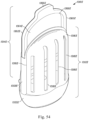
- FIG. 64 is a front perspective view of the insect trap of FIG. 62 ;
- FIG. 65 is a cross-sectional view of the insect trap of FIG. 62 ;
- FIG. 66 is a front perspective view of an example of the fifteenth embodiment of an insect trap in accordance with the principles of the disclosure.
- FIG. 67 is a front perspective view of an example of the fifteenth embodiment of an insect trap in accordance with the principles of the disclosure.
- FIG. 68 is a cross-sectional view of the insect trap of FIG. 67 ;
- FIG. 69 is a front perspective view of an example of the fifteenth embodiment of an insect trap in accordance with the principles of the disclosure.
- FIG. 70 is cross-sectional view of the insect trap of FIG. 69 ;
- FIG. 71 is an enlarged view of a portion of FIG. 70 ;
- FIG. 72 is a front perspective view of an example of the fifteenth embodiment of an insect trap in accordance with the principles of the disclosure.
- FIG. 73 is a cross-sectional view of the insect trap of FIG. 72 ;
- FIG. 74 is an enlarged view of a portion of FIG. 73 ;
- FIG. 75 is a front perspective view of an example of the fifteenth embodiment of an insect trap in accordance with the principles of the disclosure.
- FIG. 76 is a cross-sectional view of a portion of FIG. 75 ;
- FIG. 77 is an enlarged view of a portion of FIG. 76 ;
- FIG. 78 is a front perspective view of an example of the fifteenth embodiment of an insect trap in accordance with the principles of the disclosure.
- FIG. 79 is a front perspective view of a sixteenth embodiment of an insect trap in accordance with principles of the disclosure.
- FIG. 80 is a cross-sectional view of the insect trap of FIG. 79 ;
- FIG. 81 is a rear perspective view of a seventeenth embodiment of an insect trap in accordance with principles of the disclosure.
- FIG. 82 is a cross-sectional view of the insect trap of FIG. 81 ;
- FIG. 83 is an enlarged view of a portion of FIG. 82 ;
- FIG. 84 is a front perspective view of an example of the seventeenth embodiment of an insect trap in accordance with the principles of the disclosure.
- FIG. 85 is a cross-sectional view of the insect trap of FIG. 84 ;
- FIG. 86 is an enlarged view of a portion of FIG. 85 ;
- FIG. 87 is a front perspective view of an eighteenth embodiment of an insect trap in accordance with principles of the disclosure.
- FIG. 88 is a front perspective view of a nineteenth embodiment of an insect trap in accordance with principles of the disclosure.
- FIG. 89 is a rear perspective view of the insect trap of FIG. 88 ;
- FIG. 90 is a front perspective view of an example of the nineteenth embodiment of an insect trap in accordance with the principles of the disclosure.
- FIG. 91 is a rear perspective view of the insect trap of FIG. 90 ;
- FIG. 92 is a side view of the insect trap of FIG. 90 ;
- FIG. 93 is a front perspective view of an example of the nineteenth embodiment of an insect trap in accordance with the principles of the disclosure.
- FIG. 94 is a front view of an example of the nineteenth embodiment of an insect trap in accordance with the principles of the disclosure.
- FIG. 95 is a cross-sectional view of the insect of FIG. 90 ;
- FIG. 96 is a front perspective view of a twentieth embodiment of an insect trap in accordance with principles of the disclosure.
- FIG. 97 is a cross-sectional view of the insect trap of FIG. 96 ;
- FIG. 98 is a rear perspective view of a twenty-first embodiment of an insect trap in accordance with principles of the disclosure.
- FIG. 99 is a front perspective view of the insect trap of FIG. 98 ;
- FIG. 100 is a cross-sectional view of the insect trap of FIG. 98 ;
- FIG. 101 is an enlarged view of a portion of FIG. 100 ;
- FIG. 102 is a front perspective view of a twenty-second embodiment of an insect trap in accordance with principles of the disclosure.
- FIG. 103 is a front perspective view of the insect trap of FIG. 102 ;
- FIG. 104 is a front perspective view of the insect trap of FIG. 102 ;
- FIG. 105 is a cross-sectional view of the insect trap of FIG. 102 ;
- FIG. 106 is a front perspective view of an example of the twenty-second embodiment of an insect trap in accordance with the principles of the disclosure.
- FIG. 107 is a cross-sectional view of the insect trap of FIG. 106 ;
- FIG. 108 is a front perspective view of a twenty-third embodiment of an insect trap in accordance with principles of the disclosure.
- FIG. 109 is an enlarged view of a portion of FIG. 108 ;
- FIG. 110 is a cross-sectional view of the insect trap of FIG. 108 ;
- FIG. 111 is an enlarged view of a portion of FIG. 110 ;
- FIG. 112 is a cross-sectional view of the insect trap of FIG. 108 ;
- FIG. 113 is an enlarged view of a portion of FIG. 112 ;
- FIG. 114 is a front perspective view of an example of the twenty-third embodiment of an insect trap in accordance with the principles of the disclosure.
- FIG. 115 is an enlarged view of a portion of FIG. 114 ;
- FIG. 116 is a cross-sectional view of the insect trap of FIG. 114 ;
- FIG. 117 is an enlarged view of a portion of FIG. 116 ;
- FIG. 118 is a cross-sectional view of the insect trap of FIG. 114 ;
- FIG. 119 is an enlarged view of a portion of FIG. 118 ;
- FIG. 120 is a front perspective view of an example of the twenty-third embodiment of an insect trap in accordance with the principles of the disclosure.
- FIG. 121 is an exploded view of a trap portion of the insect trap of FIG. 120 :
- FIG. 122 is a cross-sectional view of the insect trap of FIG. 120 ;
- FIG. 123 is an enlarged view of a portion of FIG. 122 ;
- FIG. 124 is a cross-sectional view of the insect trap of FIG. 120 ;
- FIG. 125 is an enlarged view of a portion of FIG. 124 ;
- FIG. 126 is a front perspective view of an example of the twenty-third embodiment of an insect trap in accordance with the principles of the disclosure.
- FIG. 127 is a cross-sectional view of the insect trap of FIG. 126 ;
- FIG. 128 is an enlarged view of a portion of FIG. 127 ;
- FIG. 129 is a front perspective view of a twenty-fourth embodiment of an insect trap in accordance with principles of the disclosure.
- FIG. 130 is a front perspective view of the insect trap of FIG. 129 ;
- FIG. 131 is a cross-sectional view of the insect trap of FIG. 129 ;
- FIG. 132 is a front perspective view of a twenty-fifth embodiment of an insect trap in accordance with principles of the disclosure.
- FIG. 133 is a cross-sectional view of the insect trap of FIG. 132 ;
- FIG. 134 is a front perspective view of an example of the twenty-fifth embodiment of an insect trap in accordance with the principles of the disclosure.
- FIG. 135 is a front perspective view of an example of the twenty-fifth embodiment of an insect trap in accordance with the principles of the disclosure
- FIG. 136 is a rear perspective view of the insect trap of FIG. 135 ;
- FIG. 137 is a front perspective view of a twenty-sixth embodiment of an insect trap in accordance with principles of the disclosure.
- FIG. 138 is a cross-sectional view of the insect trap of FIG. 137 ;
- FIG. 139 is a front perspective view of a twenty-seventh embodiment of an insect trap in accordance with principles of the disclosure.
- FIG. 140 is a front perspective view of a twenty-eighth embodiment of an insect trap in accordance with the principles of the disclosure.
- FIG. 141 is a front perspective view of an example of the twenty-eighth embodiment of an insect trap in accordance with the principles of the disclosure.
- FIG. 1 is a front perspective view of an embodiment of an insect trap, indicated generally at 110 .
- Insect trap 110 includes a base portion 112 and a removable trap portion 114 .
- Insect trap 110 may have an overall length, an overall width and an overall depth, and may be configured such that when insect trap 110 is mounted to a wall, its overall depth, defined by the overall distance insect trap 110 protrudes from the wall, is the smallest of the three overall dimensions.
- a front surface 160 of base portion 112 may include a switch 116 , configurable to enable insect trap 110 to be turned on or off by closing or opening switch 116 as desired by the user.
- switch 116 may be configured to control other features such as light intensity, combinations of light wavelengths, different modes or frequencies of flickering light, an automatic setting that turns on when the room gets dark, or a remote control setting, for example.
- Switch 116 may be manually operated, although switch 116 may also be operated electrically, optically, electro-mechanically, electro-optically, or by any other method or combination of methods for opening or closing switch 116 .
- Trap portion 114 includes a front housing 118 with at least one opening 120 in a front surface 168 . Opening 120 in front housing 118 may be configured to admit a wide variety of insects into insect trap 110 , or alternatively it may be configured to admit one or more specific insect species.
- opening 120 is configured to prevent the user's fingers from penetrating opening 120 and inadvertently touching trapped insects or adhesive when removing and replacing trap portion 114 .
- opening 120 has a size and shape such that a sphere 25 mm in diameter cannot pass through opening 120 , and has a size and shape such that a sphere 1 mm in diameter can pass through any portion of opening 120 .
- Opening 120 may be of uniform or of varying width, shape and orientation, and if trap portion 114 has more than one opening 120 , they may be of identical or of differing widths, shapes and orientations. Opening 120 may be configured to attract one or more individual insect species or a variety of insect species.
- FIG. 2 is a rear perspective view of base portion 112 of insect trap 110 with trap portion 114 removed.
- Protruding from a rear surface 162 of base portion 112 are a plurality of electrically conductive prongs 122 , adapted to mount insect trap 110 to a wall and provide power to insect trap 110 by inserting conductive prongs 122 into a standard household electrical wall socket.
- conductive prongs 122 may be adapted to swivel to allow insect trap 110 to remain upright when conductive prongs 122 are inserted into a horizontally-oriented household electrical wall socket.
- base portion 112 may be configured to sit or hang wherever desired and receive power from batteries (not shown) mounted in base portion 112 .
- Base portion 112 includes a lighting element such as one or more light emitting diodes (LEDs) 124 .
- LEDs 124 include at least one that emits ultraviolet (UV) light and at least one that emits visible light.
- LEDs 124 include at least one that emits UV light and at least one that emits blue light, to better attract a wide variety of insect species.
- the lighting element emits a combination of wavelengths to mimic sunlight.
- LEDs 124 include at least one that emits infrared (IR) light, to better attract certain species of insects such as mosquitos.
- IR infrared
- top surface 126 of base portion 112 may be a transparent or translucent window 128 , shown partially cut away to reveal LEDs 124 .
- Window 128 protects LEDs 124 from dust and insect debris, and allows base portion 112 to be easily cleaned.
- top surface 126 may be a slot 130 , and on the perimeter 164 of top surface 126 is a rim or upwardly directed protrusions 132 .
- FIG. 3 is an exploded view of trap portion 114 of insect trap 110 .
- Trap portion 114 may have an overall length, an overall width and an overall depth, and may be configured such that when trap portion 114 is mounted in insect trap 110 , and insect trap 110 is mounted to a wall, the overall depth of trap portion 114 , which is measured in the direction perpendicular to the wall, is the smallest of the three overall dimensions of trap portion 114 .
- Trap portion 114 includes a divider 134 which may have a front surface 138 , and a rear housing 140 .
- divider 134 is constructed from or includes a transparent or translucent material and may be coated with a transparent or translucent adhesive 136 on front surface 138 .
- Adhesive 136 is shown partly cut away in this view.
- divider 134 is configured to polarize light transmitted through it in an orientation similar to that of daylight to further attract flying insects, a wide variety of which are known to detect polarized light.
- the material and thickness of divider 134 and the material and thickness of adhesive 136 are selected to transmit a substantial proportion of the UV and/or visible and/or IR light, for example greater than 60% of the light is transmitted through divider 134 and adhesive 136 .
- rear housing 140 includes a reflective-coated inside surface 142 .
- the material and surface finish of rear housing 140 may be configured to reflect and disperse UV and/or visible and/or IR light without a reflective coating.
- Rear housing 140 may include at least one opening 144 on its bottom surface 166 , or alternatively opening 144 may be replaced by a transparent or translucent window (not shown).
- front housing 118 and rear housing 140 are thermoformed from opaque sheet plastic. Alternatively, other opaque, transparent or translucent materials such as paper, paperboard, cardboard or paper pulp may also be used. In some embodiments, front housing 118 and rear housing 140 are constructed by injection molding, casting or by other suitable manufacturing techniques. As shown, divider 134 is substantially planar, although it may be formed into a convex, concave or saddle-shaped contour, or a combination of contours to optimize the even distribution of light. Alternatively, divider 134 may have ribs or other features that increase adhesive surface area and create regions of light/dark contrast, which are highly visible to a wide variety of insects and may be more attractive to them.
- front housing 118 may be coated with transparent, translucent or opaque adhesive on an inside surface 170 to provide additional insect trapping efficiency and capacity.
- front housing 118 may also have a reflective coating (not shown) underneath the adhesive coating on inside surface 170 to enhance its attraction to insects and further improve the insect trapping efficiency and effectiveness.
- front housing 118 , divider 134 and rear housing 140 are joined together at their perimeters with adhesive, although they may also be joined by other commonly used packaging assembly techniques such as ultrasonic welding or RF sealing, or any other suitable assembly method.
- the materials of trap portion 114 may also include one or more insect attractants.
- trap portion 114 may be impregnated with sorbitol, coleopteran attractants including brevicomin, dominicalure, frontalin, grandlure, ipsdienol, ipsenol, japonilure, lineatin, megatomoic acid, multistriatin, oryctalure, sulcatol, and trunc-call, dipteran attractants including ceralure, cue-lure, latilure, medlure, moguchun, muscalure, and trimedlure, homopteran attractants including rescalure, lepidopteran attractants such as disparlure, straight chain lepidopteran pheromones including codlelure, gossyplure, hexalure, litlure, looplure, orfralure, and ostramone, and other insect attractants such as eugenol, methyl eugenol, and siglure, or other substances to provide a scent that further
- the insect attractant is integral to trap portion 114 .
- the insect attractants may be embedded or contained in a separate piece (not shown) that mounts on inside surface 170 or an outside surface of front housing 118 or through opening 120 in front housing 118 or on front surface 138 of divider 134 .
- water may be embedded or contained in the separate part in addition to, or in place of, the one or more insect-attracting substances, as water vapor is a known mosquito attractant.
- other insect attractants such sugar solution, molasses, or honey may be embedded or contained in the separate piece in addition to, or in place of, the one or more insect-attracting substances.
- a combination of live yeast, sugar, and water, which can produce mosquito-attracting carbon dioxide may be embedded or contained in the separate part in addition to, or in place of, the one or more insect-attracting substances. It is desirable for such attractants to be detectable by an insect for approximately a 2 meter radius from insect trap 110 .
- FIG. 4 is a cross-sectional view of insect trap 110 .
- divider 134 separates trap portion 114 into a front enclosure 146 and a rear enclosure 148 .
- base portion 112 includes a circuit board 150 having a programmable processor or chip (not shown) for executing commands, electrically connected to conductive prongs 122 , only one of which is shown, switch 116 and LEDs 124 , only one of which is shown. For clarity, however, not all of the electrical connections are shown.
- Circuit board 150 may include electronic circuitry to receive ordinary household current from conductive prongs 122 , respond to the position of switch 116 and provide power to illuminate LEDs 124 .
- Circuit board 150 may include an energy stabilizer such as a full wave rectifier circuit or any other circuit that provides steady voltage to LEDs 124 when switch 116 is in the closed position, although it may also provide a varying voltage to LEDs 124 to provide a flickering light that mimics movement that some insect species, including mosquitoes, may find attractive.
- an energy stabilizer such as a full wave rectifier circuit or any other circuit that provides steady voltage to LEDs 124 when switch 116 is in the closed position, although it may also provide a varying voltage to LEDs 124 to provide a flickering light that mimics movement that some insect species, including mosquitoes, may find attractive.
- light flickering frequencies in the approximate range of 0.05 Hz (e.g., to mimic the breathing rate of large mammals) to 250 Hz (e.g., the highest flicker frequency to attract male houseflies) may be desirable and the lighting element may be configured to flicker within this range.
- Circuit board 150 may provide power to LEDs 124 to provide UV and/or visible and/or IR light, although it may be configured to provide power to only UV LEDs 124 or to only visible light LEDs 124 or to only IR light LEDS 124 , or to provide variable power to produce combinations of flickering UV and/or visible and/or IR light. Circuit board 150 may also be configured to drive a transmitter or transceiver such as a piezoelectric speaker (not shown) or other device that may be mounted in the base portion 112 to emit an insect-attracting sound.
- a transmitter or transceiver such as a piezoelectric speaker (not shown) or other device that may be mounted in the base portion 112 to emit an insect-attracting sound.
- the transmitter or transceiver may emit recorded and/or generated insect sounds or vibrations to better attract insects such as mosquitoes, midges, moths and flies, and may include one or more of insect call, reply, courtship and copulatory songs.
- the transmitter or transceiver may emit recorded and/or generated insect-attracting sounds or vibrations such as the heartbeat of a mammal.
- the transmitter or transceiver may emit an insect-attracting sound or sounds having a frequency in the range of approximately 0.5 Hz (e.g., the heart rate of large mammals) to approximately 240 kHz (e.g., the highest frequency detectable by insects). In some embodiments, the frequency is in the range of approximately 5 Hz to 100 kHz.
- the frequency is in the range of approximately 35 Hz to 50 Khz. It is desirable for such insect-attracting sound to be detectable by an insect within approximately a 2-meter distance from insect trap 110 . It is desirable for such insect-attracting sound to be undetectable by a human beyond approximately a 1-meter distance from insect trap 110 .
- Circuit board 150 may also include one or more electrical heating elements 156 such as one or more resistance heating coils, or one or more resistors, or one or more heat exchanging elements (e.g., elements using the Peltier effect and/or the Thomson effect to move heat to a specific region), or a combination of electrical elements that generate and/or move heat, which may transmit through base portion 112 and into trap portion 114 , to attract some insect species, including fleas and mosquitoes.
- one or more of LEDs 124 may generate heat, to replace or augment the heat generated by the one or more electrical elements.
- one or more of LEDs 124 may be replaced or augmented by one or more incandescent light bulbs to generate both heat and light.
- the heat generated may increase and maintain the temperature of at least a portion of trap portion 114 to between approximately 30 degrees C. and 45 degrees C., and to preferably between approximately 33 degrees C. and 42 degrees C., in order to mimic the skin and body temperatures of mammals.
- the addition of heat may also enhance the release of insect-attracting substances, including water vapor and carbon dioxide.
- a bottom surface 154 of base portion 112 may be substantially flat or concave to allow insect trap 110 to sit upright on a floor, desk, table or shelf when insect trap 110 is unplugged.
- bottom surface 154 of base portion 112 may have two or more protrusions or legs (not shown) that allow insect trap 110 to sit upright when insect trap 110 is unplugged.
- conductive prongs 122 are inserted into a wall electrical socket, and switch 116 is moved to a closed position.
- LEDs 124 emit light, represented by arrows, preferably UV and visible light, which is transmitted through window 128 in base portion 112 , through opening 144 in bottom surface 166 of rear housing 140 of trap portion 114 , into rear enclosure 148 , and directly onto inside surface 142 of rear housing 140 and a rear surface 152 of divider 134 .
- light from LEDs 124 enters rear enclosure 148 through opening 144 in bottom surface 166 of rear housing 140 of trap portion 114 (e.g., in a face that is substantially parallel to the overall depth of trap portion 114 ), the light from LEDs 124 can travel the entire length of rear enclosure 148 and can diverge over the entire length of rear enclosure 148 , and therefore can be more evenly distributed throughout rear enclosure 148 . In some embodiments, light is not manipulated in base portion 112 and is emitted directly into trap portion 114 .
- Inside surface 142 of rear housing 140 may include a concave shape and may be configured to reflect and disperse the light from LEDs 124 to distribute the light evenly onto rear surface 152 of divider 134 , although inside surface 142 of rear housing 140 may have a convex or a saddle shape or a combination of shapes, or may also have ribs or other features to more evenly distribute the light.
- an optical enhancer such as an anamorphic lens (not shown) or any other lens or combination of lenses configured to distribute the light (e.g., evenly, according to specific patterns, at a focal point, etc.) onto rear surface 152 of divider 134 , may be mounted to rear housing 140 at or near opening 144 or mounted to base portion 112 at or near window 128 , and may replace or augment the role of inside surface 142 of rear housing 140 .
- the light from LEDs 124 directly strikes rear surface 152 of divider 134 at an oblique angle (e.g., an acute angle from approximately 0° to) 90° and spreads across divider 134 , and replaces or augments the role of inside surface 142 of rear housing 140 or of the lens or lenses mounted to rear housing 140 .
- an oblique angle e.g., an acute angle from approximately 0° to 90° and spreads across divider 134 , and replaces or augments the role of inside surface 142 of rear housing 140 or of the lens or lenses mounted to rear housing 140 .
- light transmits through divider 134 and adhesive 136 on front surface 138 , and into front enclosure 146 .
- Light may be further evenly distributed by the light-diffusing properties of divider 134 , adhesive 136 on front surface 138 , or both.
- a portion of the light entering front enclosure 146 continues through opening 120 in front housing 118 and is emitted into the surrounding area where the insect trap 110 is installed. Insects are attracted to the light emitted through adhesive coating 136 and through opening 120 in front housing 118 , and fly or crawl into opening 120 and onto adhesive 136 , where they become trapped in the adhesive (e.g., from adhesive 136 ).
- a user may observe trapped insects by looking through opening 120 in front housing 118 .
- New trap portion 114 has fresh adhesive-coated surfaces and light-directing surfaces, ensuring that insect trap 110 will continue to efficiently and effectively attract and trap insects.
- insect trap 110 protrudes minimally from the wall when plugged into an ordinary household wall socket, and therefore intrudes minimally into the home environment.
- insect trap 110 is configured such that when insect trap 110 is mounted to a wall, its overall depth, defined by the overall distance insect trap 110 protrudes from the wall, is smaller than its overall height and its overall width.
- a benefit of insect trap 110 is the manipulation of light within trap portion 114 .
- light manipulation occurs solely within trap portion 114 .
- Light manipulation may include reflection, refraction, polarization, dispersion and/or diffusion and is achieved by engaging with a manipulative element or surface (e.g., inside surface 142 , divider 134 and adhesive 136 ).
- a manipulative element or surface e.g., inside surface 142 , divider 134 and adhesive 136 .
- light manipulation produces an even distribution of light on adhesive 136 .
- light is manipulated to produce a predetermined pattern on the adhesive 136 or within trap portion 114 , for example, an even distribution, an even distribution with hot spots of higher intensity, hot spot patterns, and/or combinations thereof.
- any suitable adhesive material may be used as part of an adhesive surface for trapping an insect.
- pressure sensitive adhesives such as acrylics, butyl rubber, natural rubber, nitriles, silicones, styrene block copolymers, styrene-ethylene/propylene, styrene-isoprene-styrene, vinyl ethers may be used.
- the thickness of such adhesives will be in the range of approximately 0.01 mm to 1 mm. In some embodiments, the adhesive thickness is in the range of approximately 0.05 mm to 0.2 mm, with a thickness of approximately 0.1 mm being most often used.
- An insect trap 110 of this configuration may accommodate a variety of different trap portions 114 that may be removably mounted to base portion 112 , each trap portion 114 being uniquely configured to attract and trap a specific species or multiple species of flying insect.
- the overall size and shape of trap portion 114 , and the size, shape, location and orientation of opening 120 in front housing 118 of trap portion 114 may be uniquely configured to attract and trap a specific species or multiple species of flying insect.
- trap portion 114 is approximately 20 mm to 600 mm wide, 20 mm to 600 mm high and 5 mm to 150 mm deep.
- trap portion 114 is approximately 20 mm to 200 mm wide, 20 mm to 200 mm high and 5 mm to 80 mm deep. In some embodiments, trap portion 114 is approximately 20 mm to 130 mm wide, 20 mm to 130 mm high and 5 mm to 50 mm deep.
- base portion 112 is approximately 20 mm to 600 mm wide, 10 mm to 150 mm high and 10 mm to 150 mm deep. In some embodiments, base portion 112 is 20 mm to 200 mm wide, 10 mm to 100 mm high and 10 mm to 80 mm deep. In some embodiments, base portion 112 is 20 mm to 130 mm wide, 10 mm to 50 mm high and 10 mm to 50 mm deep.
- opening 120 may be a variety of shapes and/or sizes.
- opening 120 may be circular, square, rectangular, polygonal and/or elliptical in shape.
- opening 120 may be slot shaped having a straight, curved or undulating shape or pattern.
- opening 120 may be approximately 0.5 mm to 30 mm in diameter.
- circular opening 120 is approximately 0.5 mm to 20 mm in diameter.
- circular opening 120 is approximately 0.5 mm to 15 mm in diameter.
- opening 120 When opening 120 is slot shaped, opening 120 may be approximately 2 mm to 30 mm wide and 5 mm to 500 mm long.
- slot shaped opening 120 is approximately 2 mm to 20 mm wide and 5 mm to 200 mm long.
- slot shaped opening 120 is approximately 2 mm to 15 mm wide and 5 mm to 100 mm long.
- opening 120 covers all or a portion of front housing 118 .
- opening 120 may cover a range of approximately 1% to 75% of the surface area of front housing 118 .
- opening 120 covers approximately 5% to 50% of the surface area of front housing 118 .
- opening 120 covers approximately 10% to 30% of the surface area of front housing 118 .
- FIG. 5 is a cross-sectional view of a second embodiment of an insect trap, indicated generally at 210 .
- Insect trap 210 includes a base portion 212 and a removable trap portion 214 .
- Insect trap 210 may have an overall length, an overall width and an overall depth, and may be configured such that when insect trap 210 is mounted to a wall, its overall depth, defined by the overall distance insect trap 210 protrudes from the wall, is the smallest of the three overall dimensions.
- a plurality of electrically conductive prongs 216 Protruding from a back surface 262 of base portion 212 are a plurality of electrically conductive prongs 216 , only one of which is shown, adapted to mount insect trap 210 to a wall and provide power to insect trap 210 by inserting conductive prongs 216 into a standard household electrical wall socket.
- conductive prongs 216 may be adapted to swivel to allow insect trap 210 to remain upright when conductive prongs 216 are inserted into a horizontally-oriented household electrical wall socket.
- base portion 212 may be configured to sit or hang wherever desired and receive power from batteries (not shown) mounted in base portion 212 . While an electrical socket and batteries have been described as providing power to insect trap 210 , any suitable power source may be used.
- Base portion 212 includes a lighting element such as one or more LEDs 218 , only one of which is shown.
- LEDs 218 include at least one that emits ultraviolet (UV) light and at least one that emits visible light.
- LEDs 218 include at least one that emits UV light and at least one that emits blue light to better attract a wide variety of insect species.
- the lighting element emits a combination of wavelengths to mimic sunlight.
- LEDs 218 include at least one that emits infrared (IR) light, to better attract certain species of insects such as mosquitos and fleas.
- IR infrared
- a transparent or translucent window 222 mounted in a top surface 220 of base portion 212 is a transparent or translucent window 222 .
- Window 222 protects LEDs 218 from dust and insect debris, and allows base portion 212 to be easily cleaned.
- Top surface 220 of base portion 212 may include a slot 224 , and on perimeter 270 of top surface 220 are upwardly directed protrusions 226 .
- Trap portion 214 includes a front housing 228 with at least one opening 230 and a light-conducting body 238 . Opening 230 in front housing 228 may be configured to admit a wide variety of insects into insect trap 210 , or alternatively it may be configured to admit one or more specific insect species.
- opening 230 is configured to prevent user's fingers from penetrating opening 230 and inadvertently touching trapped insects or adhesive when removing and replacing trap portion 214 .
- opening 230 has a size and shape such that a sphere 25 mm in diameter cannot pass through opening 230 , and has a size and shape such that a sphere 1 mm in diameter may pass through any portion of opening 230 .
- Opening 230 may be of uniform or of varying width, shape and orientation, and if trap portion 214 has more than one opening 230 , they may be of identical or of differing widths, shapes and orientations. Opening 230 may be configured to attract one or more individual insect species or a variety of insect species.
- light-conducting body 238 includes a front surface 254 , an adhesive coating or an adhesive layer 234 on front surface 254 , and a rear cover 248 .
- the material and thickness of adhesive layer 234 are selected to transmit a substantial proportion of the UV and/or visible and/or IR light, for example greater than 60% of the light is transmitted through adhesive layer 234 .
- Light-conducting body may be tapered and configured to receive light through a bottom surface 240 from LEDs 218 and deflect and evenly distribute the light (e.g., through front surface 254 and adhesive layer 234 ).
- Rear cover 248 may be configured to prevent light from escaping through a top surface 242 , a back surface 256 and side surfaces (not shown) of light-conducting body 238 . As provided herein, any suitable light-conducting body may be used.
- front housing 228 is thermoformed from opaque plastic sheet, although other opaque, transparent or translucent materials such as paper, paperboard, cardboard or paper pulp may also be used.
- front housing 228 is constructed by injection molding, casting or by other suitable manufacturing techniques.
- Front housing 228 may also be coated with transparent, translucent or opaque adhesive on an inside surface 250 to provide additional insect trapping efficiency and capacity.
- front housing 228 may also have a reflective coating (not shown) underneath the adhesive coating on inside surface 250 to enhance its attraction to insects and further improve the insect trapping efficiency and effectiveness.
- Front housing 228 and light-conducting body 238 may be joined together where they intersect or engage by ultrasonic welding or high frequency (HF) welding, although they may also be permanently or removably joined by adhesive or by other commonly used packaging assembly techniques or by any other suitable assembly method.
- ultrasonic welding or high frequency (HF) welding
- HF high frequency
- front housing 228 and light-conducting body 238 together form a front enclosure 246 .
- Light-conducting body 238 may be tapered (e.g., thicker at bottom surface 240 and thinner at top surface 242 ), and may be constructed from any transparent material that conducts UV and/or IR and/or visible light, such as acrylic or polycarbonate plastic.
- the inside surfaces (not shown) of rear cover 248 may have a reflective coating to reflect light back into light-conducting body 238 and through front surface 254 , thereby increasing its light-transmitting efficiency.
- Light-conducting body 238 may also have facets or other light-directing features of varying size, depth, and density on front surface 254 to enhance its light-transmitting efficiency.
- light-conducting body 238 has facets or other light-directing features on front surface 254 and not be tapered.
- Light-conducting body 238 with microscopic facets or other features on front surface 254 is commonly referred to as a Light Guide Plate, although the facets or other features may also be larger and still function effectively.
- light-conducting body 238 may not have an adhesive coating, and light conducting body 238 and rear cover 248 may be part of base portion 212 .
- trap portion 214 may include a transparent or translucent back plate (not shown) with an adhesive coating on its front surface, attached at its perimeter to front housing 228 .
- the materials of the trap portion 214 may also include one or more insect attractants.
- trap portion 214 may be impregnated with sorbitol, coleopteran attractants including brevicomin, dominicalure, frontalin, grandlure, ipsdienol, ipsenol, japonilure, lineatin, megatomoic acid, multistriatin, oryctalure, sulcatol, and trunc-call, dipteran attractants including ceralure, cue-lure, latilure, medlure, moguchun, muscalure, and trimedlure, homopteran attractants including rescalure, lepidopteran attractants such as disparlure, straight chain lepidopteran pheromones including codlelure, gossyplure, hexalure, litlure, looplure, orfralure, and ostramone, and other insect attractants such as eugenol, methyl eugen
- the insect attractant is integral to trap portion 214 .
- the insect attractants may be embedded or contained in a separate piece (not shown) that mounts on inside surface 250 or on an outside surface of front housing 228 or through opening 230 in front housing 228 or on front surface 254 of light-conducting body 238 .
- water may be embedded or contained in the separate piece in addition to, or in place of, the one or more insect-attracting substances, as water vapor is a known mosquito attractant.
- other insect attractants such sugar solution, molasses, or honey may be embedded or contained in the separate piece in addition to, or in place of, the one or more insect-attracting substances.
- a combination of live yeast, sugar, and water, which can produce mosquito-attracting carbon dioxide may be embedded or contained in the separate piece in addition to, or in place of, the one or more insect-attracting substances. It is desirable for such attractants to be detectable by an insect for approximately a 2-meter radius from insect trap 210 .
- base portion 212 includes a circuit board 252 having a programmable processor or chip (not shown) for executing commands, electrically connected to conductive prongs 216 and LEDs 218 .
- Circuit board 252 may include electronic circuitry to receive ordinary household current from conductive prongs 216 and provide power to illuminate LEDs 218 .
- Circuit board 252 may include an energy stabilizer such as a full wave rectifier circuit or any other circuit that provides steady voltage to LEDs 218 , although it may also provide a varying voltage to LEDs 218 to provide a flickering light, which may mimic movement that some species of insects, including mosquitoes, may find attractive.
- Circuit board 252 may provide power to LEDs 218 to provide UV and/or visible and/or IR light although it may be configured to provide power to only UV LEDs 218 , or to only visible light LEDs 218 , or to only IR LEDs 218 , or to provide variable power to produce combinations of flickering UV and/or visible and/or IR light.
- circuit board 252 may also be configured to drive a transmitter or transceiver such as a piezoelectric speaker or other device that may be mounted in base portion 212 to emit an insect-attracting sound.
- the transmitter or transceiver may emit recorded and/or generated insect sounds or vibrations to better attract insects such as mosquitoes, midges, moths and flies, and may include one or more of insect call, reply, courtship and copulatory songs.
- the transmitter or transceiver may emit recorded and/or generated insect-attracting sounds or vibrations such as the heartbeat of a mammal.
- the transmitter or transceiver may emit an insect-attracting sound or sounds having a frequency in the range of approximately 0.5 Hz (e.g., the heart rate of large mammals) to approximately 240 kHz (e.g., the highest frequency detectable by insects).
- the frequency is in the range of approximately 5 Hz to 100 kHz.
- the frequency is in the range of approximately 35 Hz to 50 Khz. It is desirable for such insect-attracting sound to be detectable by an insect within approximately a 2-meter distance from insect trap 210 . It is desirable for such insect-attracting sound to be undetectable by a human beyond approximately a 1 meter distance from insect trap 210 .
- Circuit board 252 may also include one or more electrical heating elements (not shown), such as resistors (not shown) or resistance heating elements (not shown), or one or more heat exchanging elements (not shown) (e.g., elements using the Peltier effect and/or the Thomson effect to move heat to a specific region), or a combination of electrical elements that generate and/or move heat, which may transmit through base portion 212 and into trap portion 214 , to attract some insect species, including fleas and mosquitoes.
- one or more of LEDs 218 may generate heat, to replace or augment the heat generated by the one or more electrical elements.
- one or more of LEDs 218 may be replaced or augmented by one or more incandescent light bulbs to generate both heat and light.
- the heat generated may increase and maintain the temperature of at least a portion of trap portion 214 to between approximately 30 degrees C. and 45 degrees C., and to preferably between approximately 33 degrees C. and 42 degrees C., in order to mimic the skin and body temperatures of mammals.
- the addition of heat may also enhance the release of insect-attracting substances, including water vapor and carbon dioxide.
- a bottom surface 236 of base portion 212 may be substantially flat or concave to allow insect trap 210 to sit upright on a floor, desk, table or shelf when insect trap 210 is unplugged.
- bottom surface 236 of base portion 212 may have two or more protrusions (not shown) or legs that allow insect trap 210 to sit upright when insect trap 210 is unplugged.
- conductive prongs 216 are inserted into a wall electrical socket, and LEDs 218 emit light, represented by arrows, preferably UV and visible light.
- the light from LEDs 218 transmit through window 222 , enter bottom surface 240 of light-conducting body 238 and repeatedly reflect off of front surface 254 and back surface 256 .
- light is not manipulated in base portion 212 and is emitted directly into trap portion 214 .
- a portion of the reflected light transmits through front surface 254 of light-conducting body 238 to provide an evenly-distributed light onto and through adhesive layer 234 and into front enclosure 246 .
- the light may be further evenly distributed by refractive and light-diffusing properties of adhesive layer 234 on front surface 254 of light-conducting body 238 .
- a portion of the light entering front enclosure 246 continues through opening 230 in front housing 228 and is emitted into the surrounding area where insect trap 210 is installed. Insects are attracted to the light transmitted through adhesive layer 234 and through opening 230 in front housing 228 , and fly or crawl through opening 230 and onto adhesive layer 234 , where they become trapped in the adhesive.
- the user may observe trapped insects by looking through opening 230 in front housing 228 .
- New trap portion 214 has fresh adhesive-coated surfaces and light-directing surfaces, ensuring that insect trap 210 will continue to efficiently and effectively attract and trap insects.
- insect trap 210 protrudes minimally from the wall when plugged into an ordinary household wall socket, and therefore intrudes minimally into the home environment.
- insect trap 210 is configured such that when insect trap 210 is mounted to a wall, its overall depth, defined by the overall distance insect trap 210 protrudes from the wall, is smaller than its overall height and its overall width.
- a benefit of insect trap 210 is the manipulation of light within trap portion 214 .
- light manipulation occurs solely within trap portion 214 .
- Light manipulation may include reflection, refraction, polarization and/or diffusion and is achieved by engaging with a manipulative element or surface (e.g., light-conducting body 238 , front surface 254 , back surface 256 , and adhesive layer 234 ).
- a manipulative element or surface e.g., light-conducting body 238 , front surface 254 , back surface 256 , and adhesive layer 234 .
- light manipulation produces an even distribution of light on adhesive layer 234 .
- light is manipulated to produce a predetermined pattern on adhesive layer 234 or within trap portion 214 , for example, an even distribution, an even distribution with hot spots of higher intensity, hot spot patterns, and/or combinations thereof.
- any suitable adhesive material may be used as part of an adhesive surface for trapping an insect.
- pressure sensitive adhesives such as acrylics, butyl rubber, natural rubber, nitriles, silicones, styrene block copolymers, styrene-ethylene/propylene, styrene-isoprene-styrene, vinyl ethers may be used.
- the thickness of such adhesives will be in the range of approximately 0.01 mm to 1 mm. In some embodiments, the adhesive thickness is in the range of approximately 0.05 mm to 0.2 mm, with a thickness of approximately 0.1 mm being most often used.
- Insect trap 210 of this configuration may accommodate a variety of different trap portions 214 that may be removably mounted to base portion 212 , each trap portion 214 being uniquely configured to attract and trap a specific species or multiple species of insects.
- the overall size and shape of trap portion 214 , and the size, shape, location and orientation of opening 230 in front housing 228 of trap portion 214 may be uniquely configured to attract and trap a specific species or multiple species of insects.
- trap portion 214 is approximately 20 mm to 600 mm wide, 20 mm to 600 mm high and 5 mm to 150 mm deep.
- trap portion 214 is approximately 20 mm to 200 mm wide, 20 mm to 200 mm high and 5 mm to 80 mm deep. In some embodiments, trap portion 214 is approximately 20 mm to 130 mm wide, 20 mm to 130 mm high and 5 mm to 50 mm deep.
- base portion 212 is approximately 20 mm to 600 mm wide, 10 mm to 150 mm high and 10 mm to 150 mm deep. In some embodiments, base portion 212 is 20 mm to 200 mm wide, 10 mm to 100 mm high and 10 mm to 80 mm deep. In some embodiments, base portion 212 is 20 mm to 130 mm wide, 10 mm to 50 mm high and 10 mm to 50 mm deep.
- opening 230 may be a variety of shapes and/or sizes.
- opening 230 may be circular, square, rectangular, polygonal and/or elliptical in shape.
- opening 230 may be slot shaped having a straight, curved or undulating shape or pattern.
- opening 230 may be approximately 0.5 mm to 30 mm in diameter.
- circular opening 230 is approximately 0.5 mm to 20 mm in diameter.
- circular opening 230 is approximately 0.5 mm to 15 mm in diameter.
- opening 230 When opening 230 is slot shaped, opening 230 may be approximately 2 mm to 30 mm wide and 5 mm to 500 mm long.
- slot shaped opening 230 is approximately 2 mm to 20 mm wide and 5 mm to 200 mm long.
- slot shaped opening 230 is approximately 2 mm to 15 mm wide and 5 mm to 100 mm long.
- opening 230 covers all or a portion of front housing 228 .
- opening 230 may cover a range of approximately 1% to 75% of the surface area of front housing 228 .
- opening 230 covers approximately 5% to 50% of the surface area of front housing 228 .
- opening 230 covers approximately 10% to 30% of the surface area of front housing 228 .
- FIG. 6 is a front perspective view of a third embodiment of an insect trap, indicated generally at 310 .
- Insect trap 310 may include a base portion 312 and a removable trap portion 314 .
- Insect trap 310 may have an overall length, an overall width and an overall depth, and may be configured such that when insect trap 310 is mounted to a wall, its overall depth, defined by the overall distance insect trap 310 protrudes from the wall, is the smallest of the three overall dimensions.
- front surface 360 of base portion 312 includes a switch 316 , configurable to enable insect trap 310 to be turned on or off by closing or opening switch 316 as desired by the user.
- switch 316 may be configured to control other features such as light intensity, combinations of light wavelengths, different flickering frequencies or modes, an automatic setting that turns on when the room gets dark, or a remote control setting, for example.
- Switch 316 may be manually operated, although switch 316 may also be operated electrically, optically, electro-mechanically, electro-optically, or by any method for opening or closing switch 316 .
- Trap portion 314 may include a housing 318 with at least one opening 320 . Opening 320 in housing 318 may be configured to admit a wide variety of insects into insect trap 310 , or alternatively it may be configured to admit one or more specific insect species.
- Opening 320 may preferably be configured to prevent user's fingers from penetrating opening 320 and inadvertently touching trapped insects or adhesive when removing and replacing trap portion 314 .
- Opening 320 may preferably have a size and shape such that a sphere 25 mm in diameter cannot pass through opening 320 , and opening 320 may preferably have a size and shape such that a sphere 1 mm in diameter may pass through any portion of opening 320 .
- Opening 320 may be of uniform or of varying width, shape and orientation, and if trap portion 314 has more than one opening 320 , they may be of identical or of differing widths, shapes and orientations.
- FIG. 7 is a rear perspective view of base portion 312 of insect trap 310 .
- Protruding from a rear surface 362 of base portion 312 are a plurality of electrically conductive prongs 322 , adapted to mount insect trap 310 to a wall and provide power to insect trap 310 by inserting into a standard household electrical wall socket.
- conductive prongs 322 may be adapted to swivel to allow insect trap 310 to remain upright when conductive prongs 322 are inserted into a horizontally-oriented household electrical wall socket.
- base portion 312 may be configured to sit or hang wherever desired and receive power from batteries (not shown) mounted in base portion 312 .
- Base portion 312 includes a lighting element such as one or more LEDs 324 .
- LEDs 324 include one that emits ultraviolet (UV) light and one that emits visible light.
- LEDs 324 include at least one that emits UV light and at least one that emits blue light to better attract a wide variety of insect species.
- the lighting element emits a combination of wavelengths to mimic sunlight.
- LEDs 324 include at least one that emits infrared (IR) light to better attract certain species of insects such as mosquitos and fleas.
- IR infrared
- a transparent or translucent window 328 Mounted in a top surface 326 of base portion 312 may be a transparent or translucent window 328 , shown partially cut away to reveal LEDs 324 .
- Window 328 protects LEDs 324 from dust and insect debris, and allows base portion 312 to be easily cleaned.
- Upwardly directed protrusions or a rim 330 protruding from the perimeter 364 of top surface 326 of base portion 312 may serve to secure trap portion 314 in place during use, although any other form of attachment may be substituted that allows trap portion 314 to be securely but removably mounted to base portion 312 .
- FIG. 8 is a front perspective view of trap portion 314 of insect trap 310 .
- Trap portion 314 includes housing 318 , which forms an enclosure, and a transparent or translucent adhesive coating applied to one or more inside surfaces 334 .
- the material and thickness of housing 318 and the material and thickness of the adhesive coating are selected to transmit a substantial proportion of the UV and/or visible and/or IR light, for example greater than 60% of the light is transmitted through housing 318 and the adhesive coating.
- housing 318 is thermoformed from opaque plastic sheet, although other opaque, transparent or translucent materials such as paper, paperboard, cardboard or paper pulp may also be used.
- housing 318 is constructed by injection molding or by other suitable manufacturing techniques.
- housing 318 includes ribs 336 or other features that increase the adhesive-coated surface area, produce alternating light/dark regions that some insect species find attractive, and enhance the transmission of insect-attracting light into an interior 370 of trap portion 314 .
- a sleeve 338 configured to reduce the amount of light emitted by an outside surface 368 of housing 318 , covers outside surface 368 of housing 318 except for a bottom surface 366 and at opening 320 .
- sleeve 338 is thermoformed from opaque sheet plastic, although other opaque, transparent or translucent materials such as paper, paperboard, cardboard or paper pulp may also be used.
- sleeve 338 includes a reflective coating on one or more of its inside surfaces (not shown), allowing sleeve 338 to direct more light through inside surfaces 334 of housing 318 and further enhance the insect attracting and trapping efficiency and effectiveness.
- sleeve 338 is replaced by a coating configured to reduce the amount of light emitted by outside surface 368 of housing 318 , or by the coating applied over a reflective coating, applied to outside surface 368 of housing 318 , except for bottom surface 366 .
- the materials of the trap portion 314 may also include one or more insect attractants.
- trap portion 314 may be impregnated with sorbitol, coleopteran attractants including brevicomin, dominicalure, frontalin, grandlure, ipsdienol, ipsenol, japonilure, lineatin, megatomoic acid, multistriatin, oryctalure, sulcatol, and trunc-call, dipteran attractants including ceralure, cue-lure, latilure, medlure, moguchun, muscalure, and trimedlure, homopteran attractants including rescalure, lepidopteran attractants such as disparlure, straight chain lepidopteran pheromones including codlelure, gossyplure, hexalure, litlure, looplure, orfralure, and ostramone, and other insect attractants such as eugenol, methyl eugen
- the insect attractant is integral to trap portion 314 .
- the insect attractants may be embedded or contained in a separate piece (not shown) that mounts on inside surfaces 334 of housing 318 or through opening 320 in housing 318 .
- water may be embedded or contained in the separate piece in addition to, or in place of, the one or more insect-attracting substances, as water vapor is a known mosquito attractant.
- other insect attractants such sugar solution, molasses, or honey may be embedded or contained in the separate piece in addition to, or in place of, the one or more insect-attracting substances.
- a combination of live yeast, sugar, and water, which can produce mosquito-attracting carbon dioxide may be embedded or contained in the separate piece in addition to, or in place of, the one or more insect-attracting substances. It is desirable for such attractants to be detectable by an insect for approximately a 2-meter radius from insect trap 310 .
- FIG. 9 is a cross-sectional view of insect trap 310 .
- base portion 312 includes a circuit board 340 having a programmable processor or chip (not shown) for executing commands, electrically connected to conductive prongs 322 , only one of which is shown, switch 316 and LEDs 324 , only one of which is shown. For clarity, however, not all of the electrical connections are shown.
- Circuit board 340 may include electronic circuitry to receive ordinary household current from conductive prongs 322 , respond to the position of switch 316 and provide power to illuminate LEDs 324 .
- Circuit board 340 may include an energy stabilizer such as a full wave rectifier filter circuit or any other circuit that provides steady voltage to LEDs 324 when switch 316 is in a closed position, although it may also provide a varying voltage to LEDs 324 to provide a flickering light, which may mimic movement that some insect species, including mosquitoes, may find attractive.
- an energy stabilizer such as a full wave rectifier filter circuit or any other circuit that provides steady voltage to LEDs 324 when switch 316 is in a closed position, although it may also provide a varying voltage to LEDs 324 to provide a flickering light, which may mimic movement that some insect species, including mosquitoes, may find attractive.
- light flickering frequencies in the approximate range of 0.05 Hz e.g., to mimic the breathing rate of mammals
- 250 Hz e.g., the highest flicker frequency attracting male houseflies
- Circuit board 340 may provide power to LEDs 324 to provide both UV and/or visible and/or IR light, although it could be configured to provide power to only the UV LEDs 324 or to only the visible light LEDs 324 or to only the IR LEDs 324 , or to provide variable power to produce combinations of flickering UV and/or visible and/or IR light.
- circuit board 340 may also be configured to drive a transmitter or transceiver such as a piezoelectric speaker or other device that may be mounted in base portion 312 to emit an insect-attracting sound.
- the transmitter or transceiver may emit recorded and/or generated insect sounds or vibrations to better attract insects such as mosquitoes, midges, moths and flies, and may include one or more of insect call, reply, courtship and copulatory songs.
- the transmitter or transceiver may emit recorded and/or generated insect-attracting sounds or vibrations such as the heartbeat of a mammal.
- the transmitter or transceiver may emit an insect-attracting sound or sounds having a frequency in the range of approximately 0.5 Hz (e.g., the heart rate of large mammals) to approximately 240 kHz (e.g., the highest frequency detectable by insects). In some embodiments, the frequency is in the range of approximately 5 Hz to 100 kHz.
- Circuit board 340 may also include one or more electrical heating elements 342 such as one or more resistors or resistance heating elements, or one or more heat exchanging elements (e.g., elements using the Peltier effect and/or the Thomson effect to move heat to a specific region), or a combination of electrical elements that generate and/or move heat, which may transmit through base portion 312 and into trap portion 314 , to attract some insect species, including fleas and mosquitoes.
- electrical heating elements 342 such as one or more resistors or resistance heating elements, or one or more heat exchanging elements (e.g., elements using the Peltier effect and/or the Thomson effect to move heat to a specific region), or a combination of electrical elements that generate and/or move heat, which may transmit through base portion 312 and into trap portion 314 , to attract some insect species, including fleas and mosquitoes.
- one or more of LEDs 324 may generate heat, to replace or augment the heat generated by the one or more electrical elements.
- one or more of LEDs 324 may be replaced or augmented by one or more incandescent light bulbs to generate both heat and light.
- the heat generated may increase and maintain the temperature of at least a portion of trap portion 314 to between approximately 30 degrees C. and 45 degrees C., and to preferably between approximately 33 degrees C. and 42 degrees C., in order to mimic the skin and body temperatures of mammals.
- the addition of heat may also enhance the release of insect-attracting substances, including water vapor and carbon dioxide.
- conductive prongs 322 are inserted into a wall electrical socket and switch 316 is moved to a closed position.
- LEDs 324 emit light, represented by arrows, which transmits through window 328 in base portion 312 and through bottom surface 366 of housing 318 .
- light is not manipulated in base portion 312 and is emitted directly into trap portion 314 .
- a portion of the light continues within the enclosure, up one or more sides 372 of housing 318 , and out through inside surfaces 334 .
- Another portion of the light continues through bottom surface 366 of housing 318 and into the enclosure, where it illuminates inside surfaces 334 .
- a portion of the light entering housing 318 continues through opening 320 and is emitted into the surrounding area where the trap is installed. Insects in the area are attracted to the light transmitted through opening 320 and fly or crawl into opening 320 and onto inside surfaces 334 , where they become stuck in the adhesive and are trapped. The user may observe trapped insects by looking through opening 320 . When a sufficient number of insects have been trapped, the user may easily remove and discard the entire used trap portion 314 without touching trapped insects, insect debris or adhesive, which remain out of reach inside trap portion 314 , and replace it with a new trap portion 314 .
- New trap portion 314 has fresh adhesive-coated inside surfaces 334 , housing 318 has a clean bottom surface 366 through which the light is transmitted into trap portion 314 , and the transparent or translucent material of trap portion 314 has not been degraded by prolonged exposure to UV light from LEDs 324 , thereby ensuring that insect trap 310 will continue to efficiently and effectively attract and trap insects.
- insect trap 310 protrudes minimally from the wall when plugged into an ordinary household wall socket, and therefore intrudes minimally into the home environment.
- insect trap 310 is configured such that when insect trap 310 is mounted to a wall, its overall depth, defined by the overall distance insect trap 310 protrudes from the wall, is smaller than its overall height and its overall width.
- a benefit of insect trap 310 is the manipulation of light within trap portion 314 .
- light manipulation occurs solely within trap portion 314 .
- Light manipulation may include reflection, refraction, polarization, dispersion and/or diffusion and is achieved by engaging with a manipulative element or surface (e.g., housing 318 and inside surfaces 334 ).
- a manipulative element or surface e.g., housing 318 and inside surfaces 334 .
- light manipulation produces an even distribution of light on an adhesive surface or adhesive coating.
- light is manipulated to produce a predetermined pattern on the adhesive coating or within trap portion 314 , for example, an even distribution, an even distribution with hot spots of higher intensity, hot spot patterns, and/or combinations thereof.
- any suitable adhesive material may be used as part of an adhesive surface for trapping an insect.
- pressure sensitive adhesives such as acrylics, butyl rubber, natural rubber, nitriles, silicones, styrene block copolymers, styrene-ethylene/propylene, styrene-isoprene-styrene, vinyl ethers may be used.
- the thickness of such adhesives will be in the range of approximately 0.01 mm to 1 mm. In some embodiments, the adhesive thickness is in the range of approximately 0.05 mm to 0.2 mm, with a thickness of approximately 0.1 mm being most often used.
- Insect trap 310 of this configuration may accommodate a variety of different trap portions 314 that may be removably mounted to base portion 312 , each trap portion 314 being uniquely configured to attract and trap a specific species or multiple species of insects.
- the overall size and shape of trap portion 314 , and the size, shape, location and orientation of opening 320 in housing 318 of trap portion 314 may be uniquely configured to attract and trap a specific species or multiple species of insects.
- trap portion 314 is approximately 20 mm to 600 mm wide, 20 mm to 600 mm high and 5 mm to 150 mm deep.
- trap portion 314 is approximately 20 mm to 200 mm wide, 20 mm to 200 mm high and 5 mm to 80 mm deep. In some embodiments, trap portion 314 is approximately 20 mm to 130 mm wide, 20 mm to 130 mm high and 5 mm to 50 mm deep.
- base portion 312 is approximately 20 mm to 600 mm wide, 10 mm to 150 mm high and 10 mm to 150 mm deep. In some embodiments, base portion 312 is 20 mm to 200 mm wide, 10 mm to 100 mm high and 10 mm to 80 mm deep. In some embodiments, base portion 312 is 20 mm to 130 mm wide, 10 mm to 50 mm high and 10 mm to 50 mm deep.
- opening 320 may be a variety of shapes and/or sizes.
- opening 320 may be circular, square, rectangular, polygonal and/or elliptical in shape.
- opening 320 may be slot shaped having a straight, curved or undulating shape or pattern.
- opening 320 may be approximately 0.5 mm to 30 mm in diameter.
- circular opening 320 is approximately 0.5 mm to 20 mm in diameter.
- circular opening 320 is approximately 0.5 mm to 15 mm in diameter.
- opening 320 may be approximately 2 mm to 30 mm wide and 5 mm to 500 mm long.
- slot shaped opening 320 is approximately 2 mm to 20 mm wide and 5 mm to 200 mm long.
- slot shaped opening 320 is approximately 2 mm to 15 mm wide and 5 mm to 100 mm long.
- opening 320 covers all or a portion of trap portion 314 .
- opening 320 may cover a range of approximately 1% to 75% of the surface area of trap portion 314 .
- opening 320 covers approximately 5% to 50% of the surface area of trap portion 314 .
- opening 320 covers approximately 10% to 30% of the surface area of trap portion 314 .
- FIGS. 10 and 11 show a fourth embodiment of an insect trap, where the trap portion mounts to the front of the base portion.
- FIG. 10 is a front perspective view and FIG. 11 is a rear perspective view, both showing a fourth embodiment of an insect trap, indicated generally at 410 .
- Insect trap 410 includes a base portion 412 and a removable trap portion 420 . Trap portion 420 is shown removed from base portion 412 in both views. Protruding from a rear surface 432 of base portion 412 are a plurality of electrically conductive prongs 434 , adapted to mount insect trap 410 to a wall and provide power to insect trap 410 by inserting into a standard household electrical wall socket. Alternatively, base portion 412 may be configured to sit or hang wherever desired and receive power from batteries (not shown) mounted in base portion 412 .
- a lighting element such as one or more LEDs 414 may be mounted on a cross-shaped protrusion 416 protruding from a front surface 418 of base portion 412 .
- LEDs 414 may form a protrusion themselves. While shown as a cross-shaped protrusion, the mounting surface and/or configuration of LEDs 414 may be any desired shape.
- base portion 412 includes a circuit board (not shown) having a programmable processor or chip (not shown) for executing commands, electrically connected to conductive prongs 434 and LEDs 414 .
- Trap portion 420 includes a housing 450 of translucent or transparent material with one or more adhesive-coated inside surfaces 422 and at least one opening 424 .
- the material and thickness of housing 450 and the material and thickness of the adhesive are selected to transmit a substantial proportion of the light, for example greater than 60% of the light is transmitted through housing 450 and the adhesive coating.
- Opening 424 may be configured to admit a wide variety of insects into insect trap 410 , or alternatively it may be configured to admit one or more specific insect species. Opening 424 may be configured to prevent user's fingers from penetrating opening 424 and inadvertently touching trapped insects or adhesive when removing and replacing trap portion 420 .
- Opening 424 may preferably have a size and shape such that a sphere 25 mm in diameter cannot pass through the at least one opening 424 , and opening 424 may preferably have a size and shape such that a sphere 1 mm in diameter may pass through any portion of opening 424 .
- Opening 424 may be of uniform or of varying width, shape and orientation, and if trap portion 420 has more than one opening 424 , they may be of identical or of differing widths, shapes and orientations.
- Trap portion 420 may include a coating (not shown) configured to reduce the amount of light emitted by its outside surfaces 452 , on outside surfaces 452 except for at opening 424 and at a cross-shaped blind cavity 426 in its rear surface 428 .
- blind cavity 426 is cross-shaped 454 , but may be any desired shape.
- cross-shaped protrusion 416 on front surface 418 of base portion 412 may engage with a recess in cross-shaped cavity 454 in rear surface 428 of trap portion 420 to removably attach trap portion 420 to base portion 412 .
- trap portion 420 mounts in front of base portion 412 .
- base portion 412 is plugged into an electrical wall socket and trap portion 420 is mounted in front of base portion 412 .
- Light from LEDs 414 transmit into cross-shaped cavity 454 in rear surface 428 of trap portion 420 .
- light is not manipulated in base portion 412 and is emitted directly into trap portion 420 .
- a portion of the light continues within the translucent or transparent walls of trap portion 420 , diffusing the light and spreading it evenly within trap portion 420 and through inside surfaces 422 .
- Another portion of the light continues through the rear wall of trap portion 420 and into the interior 430 of trap portion 420 , where it illuminates inside surfaces 422 .
- a portion of the light entering trap portion 420 continues through opening 424 and into the room where insect trap 410 is installed. Insects in the room are attracted to the light transmitted through opening 424 , and fly or crawl into opening 424 and onto inside surfaces 422 , where they become stuck in the adhesive and are trapped. The user may observe trapped insects by looking through opening 424 . When a sufficient number of insects have been trapped, the user may easily remove and discard the entire used trap portion 420 without touching the trapped insects, insect debris or adhesive, which remain out of reach inside trap portion 420 , and replace it with a new trap portion 420 .
- the new trap portion 420 has fresh adhesive-coated inside surfaces 422 , a clean cross-shaped cavity 426 in rear surface 428 through which the light is transmitted into trap portion 420 , and the transparent or translucent material of trap portion 420 has not been degraded by prolonged exposure to UV light from LEDs 414 , thereby ensuring that insect trap 410 will continue to efficiently and effectively attract and trap insects.
- a benefit of insect trap 410 is the manipulation of light within trap portion 420 .
- light manipulation occurs solely within trap portion 420 .
- Light manipulation may include reflection, refraction, polarization, dispersion and/or diffusion and is achieved by engaging with a manipulative element or surface (e.g., trap portion 420 and inside surfaces 422 ).
- a manipulative element or surface e.g., trap portion 420 and inside surfaces 422 .
- light manipulation produces an even distribution of light on an adhesive surface or adhesive coating.
- light is manipulated to produce a predetermined pattern on the adhesive coating or within trap portion 420 , for example, an even distribution, an even distribution with hot spots of higher intensity, hot spot patterns, and/or combinations thereof.
- any suitable adhesive material may be used as part of an adhesive surface for trapping an insect.
- pressure sensitive adhesives such as acrylics, butyl rubber, natural rubber, nitriles, silicones, styrene block copolymers, styrene-ethylene/propylene, styrene-isoprene-styrene, vinyl ethers may be used.
- the thickness of such adhesives will be in the range of approximately 0.01 mm to 1 mm. In some embodiments, the adhesive thickness is in the range of approximately 0.05 mm to 0.2 mm, with a thickness of approximately 0.1 mm being most often used.
- An insect trap 410 of this configuration may accommodate a variety of different trap portions 420 that may be removably mounted to base portion 412 , each trap portion 420 being uniquely configured to attract and trap a specific species or multiple species of insects.
- the overall size and shape of trap portion 420 , and the size, shape, location and orientation of opening 424 in trap portion 420 may be uniquely configured to attract and trap a specific species or multiple species of insects.
- trap portion 420 is approximately 20 mm to 600 mm wide, 20 mm to 600 mm high and 5 mm to 150 mm deep.
- trap portion 420 is approximately 20 mm to 200 mm wide, 20 mm to 200 mm high and 5 mm to 80 mm deep.
- trap portion 420 is approximately 20 mm to 130 mm wide, 20 mm to 130 mm high and 5 mm to 50 mm deep.
- base portion 412 is approximately 10 mm to 600 mm wide, 10 mm to 150 mm high and 10 mm to 150 mm deep. In some embodiments, base portion 412 is 10 mm to 200 mm wide, 10 mm to 100 mm high and 10 mm to 80 mm deep. In some embodiments, base portion 412 is 10 mm to 130 mm wide, 10 mm to 50 mm high and 10 mm to 50 mm deep.
- opening 424 may be a variety of shapes and/or sizes.
- opening 424 may be circular, square, rectangular, polygonal and/or elliptical in shape.
- opening 424 may be slot shaped having a straight, curved or undulating shape or pattern.
- opening 424 may be approximately 0.5 mm to 30 mm in diameter.
- circular opening 424 is approximately 0.5 mm to 20 mm in diameter.
- circular opening 424 is approximately 0.5 mm to 15 mm in diameter.
- opening 424 may be approximately 2 mm to 30 mm wide and 5 mm to 500 mm long.
- slot shaped opening 424 is approximately 2 mm to 20 mm wide and 5 mm to 200 mm long.
- slot shaped opening 424 is approximately 2 mm to 15 mm wide and 5 mm to 100 mm long.
- opening 424 covers all or a portion of trap portion 420 .
- opening 424 may cover a range of approximately 1% to 75% of the surface area of trap portion 420 .
- opening 424 covers approximately 5% to 50% of the surface area of trap portion 420 .
- opening 424 covers approximately 10% to 30% of the surface area of trap portion 420 .
- FIG. 12 is a front perspective view and FIG. 13 is a rear perspective view showing a fifth embodiment of an insect trap, indicated generally at 510 .
- Insect trap 510 includes a base portion 512 and a removable trap portion 514 .
- Insect trap 510 may have an overall length, an overall width and an overall depth, and may be configured such that when insect trap 510 is mounted to a wall, its overall depth, defined by the overall distance insect trap 510 protrudes from the wall, is the smallest of the three overall dimensions.
- Base portion 512 includes a housing 516 with a top opening 518 on its top surface 560 to receive trap portion 514 , at least one front opening 520 on its front surface 562 , and a plurality of electrically conductive prongs 522 on its rear surface 564 , adapted to mount insect trap 510 to a wall and provide power to insect trap 510 by inserting into a standard household electrical wall socket.
- conductive prongs 522 may be adapted to swivel to allow insect trap 510 to remain upright when conductive prongs 522 are inserted into a horizontally oriented electrical wall socket.
- base portion 512 may be configured to sit or hang wherever desired and receive power from batteries (not shown) mounted in base portion 512 .
- Front opening 520 may be configured to admit a wide variety of insects into insect trap 510 , or alternatively it may be configured to admit one or more specific insect species. Front opening 520 may be configured to prevent user's fingers from penetrating front opening 520 and inadvertently touching trapped insects or adhesive when removing and replacing trap portion 514 . Front opening 520 may preferably have a size and shape such that a sphere 25 mm in diameter cannot pass through front opening 520 , and front opening 520 may preferably have a size and shape such that a sphere 1 mm in diameter may pass through any portion of front opening 520 .
- Front opening 520 may be of uniform or of varying width, shape and orientation, and if trap portion 514 has more than one front opening 520 , they may be of identical or of differing widths, shapes and orientations.
- base portion 512 is injection molded of opaque plastic, although other materials and construction techniques could also be used.
- FIG. 14 is a front perspective view of insect trap 510 .
- Trap portion 514 is shown partially removed from base portion 512 in this view.
- Trap portion 514 may include a housing 524 with at least one opening 526 and a tab 528 adapted for removing and replacing trap portion 514 .
- Trap portion 514 may be removed by grasping tab 528 and lifting trap portion 514 out of housing 516 of base portion 512 .
- Opening 526 in trap portion 514 may correspond to front opening 520 in base portion 512 with respect to size, shape, orientation and location, so that they may align when trap portion 514 is mounted into base portion 512 .
- trap portion 514 may be viewed as an inner sleeve or pocket and base portion 512 may be viewed as an outer sleeve, where the inner sleeve can be dropped or inserted into the outer sleeve by a user.
- FIG. 15 is a front perspective view of trap portion 514 .
- Trap portion 514 is shown partially cut away in this view.
- Housing 524 may include inside surfaces 530 coated with translucent or transparent adhesive.
- housing 524 includes ribs 532 or other features that increase the adhesive-coated surface area, produce alternating light/dark regions that some insect species find attractive, and enhance the transmission of insect-attracting light into the interior of trap portion 514 .
- trap portion 514 is thermoformed of translucent or transparent sheet plastic, in two separate pieces, or in a ‘clamshell’ configuration, in which the two sides are joined at one side and folded together, although trap portion 514 could also be injection molded of translucent or transparent plastic or constructed of translucent paper or of other materials.
- the material and thickness of trap portion 514 and the material and thickness of the adhesive are selected to transmit a substantial proportion of light, for example greater than 60% of light is transmitted through trap portion 514 and the adhesive coating.
- the materials of trap portion 514 may also include one or more insect attractants.
- trap portion 514 may be impregnated with sorbitol, coleopteran attractants including brevicomin, dominicalure, frontalin, grandlure, ipsdienol, ipsenol, japonilure, lineatin, megatomoic acid, multistriatin, oryctalure, sulcatol, and trunc-call, dipteran attractants including ceralure, cue-lure, latilure, medlure, moguchun, muscalure, and trimedlure, homopteran attractants including rescalure, lepidopteran attractants such as disparlure, straight chain lepidopteran pheromones including codlelure, gossyplure, hexalure, litlure, looplure, orfralure, and ostramone, and other insect attractants such as eugenol, methyl eugenol, and siglure, or other substances to provide a scent that increases
- the insect attractant is integral to trap portion 514 .
- the insect attractants may be embedded or contained in a separate piece (not shown) that mounts on inside surfaces 530 of housing 524 or through opening 526 in housing 524 .
- water may be embedded or contained in the separate piece in addition to, or in place of, the one or more insect-attracting substances, as water vapor is a known mosquito attractant.
- other insect attractants such sugar solution, molasses, or honey may be embedded or contained in the separate piece in addition to, or in place of, the one or more insect-attracting substances.
- a combination of live yeast, sugar, and water, which can produce mosquito-attracting carbon dioxide may be embedded or contained in the separate piece in addition to, or in place of, the one or more insect-attracting substances. It is desirable for such attractants to be detectable by an insect for approximately a 2-meter radius from insect trap 510 .
- FIG. 16 is a cross-sectional view of insect trap 510 .
- base portion 512 includes a circuit board 534 having a programmable processor or chip (not shown) for executing commands, electrically connected to conductive prongs 522 , only one of which is shown, and a lighting element such as one or more LEDs 536 , only one of which is shown.
- LEDs 536 include one that emits ultraviolet (UV) light and one that emits visible light.
- LEDs 536 include at least one that emits UV light and at least one that emits blue light to better attract a wide variety of insect species.
- the lighting element emits a combination of wavelengths to mimic sunlight.
- LEDs 536 include at least one that emits infrared (IR) light to better attract certain species of insects such as mosquitos and fleas. For clarity, not all of the electrical connections are shown.
- Circuit board 534 may include electronic circuitry to receive any household current from conductive prongs 522 and provide power to LEDs 536 .
- circuit board 534 may be configured to receive power from batteries (not shown) mounted in base portion 512 . While an electrical socket and batteries have been described as providing power to insect trap 510 , any suitable power source may be used.
- Circuit board 534 may include a full wave rectifier circuit or any other circuit to provide steady voltage to LEDs 536 , although it could also provide a varying voltage to LEDs 536 to provide a flickering light, which mimics movement that some insect species, including mosquitoes, may find attractive.
- light flickering frequencies in the approximate range of 0.05 Hz (e.g., to mimic the breathing rate of mammals) to 270 Hz (e.g., the highest flicker frequency known to attract male houseflies) may be desirable and the lighting element may be configured to flicker within this range.
- Circuit board 534 may provide power to LEDs 536 to provide UV and/or visible and/or IR light, although it could be configured to provide power to only the UV LEDs 536 or to only the visible light LEDs 536 , or to provide variable power to produce combinations of flickering UV and/or visible and/or IR light.
- circuit board 534 may also be configured to drive a transmitter or transceiver such as a piezoelectric speaker or other device that may be mounted in base portion 512 to emit an insect-attracting sound.
- the transmitter or transceiver may emit recorded and/or generated insect sounds or vibrations to better attract insects such as mosquitoes, midges, moths and flies, and may include one or more of insect call, reply, courtship and copulatory songs.
- the transmitter or transceiver may emit recorded and/or generated insect-attracting sounds or vibrations such as the heartbeat of a mammal.
- the transmitter or transceiver may emit an insect-attracting sound or sounds having a frequency in the range of approximately 0.5 Hz (e.g., the heart rate of large mammals) to approximately 240 kHz (e.g., the highest frequency detectable by insects). In some embodiments, the frequency is in the range of approximately 5 Hz to 100 kHz.
- the frequency is in the range of approximately 35 Hz to 50 Khz. It is desirable for such insect-attracting sound to be detectable by an insect within approximately a 2-meter distance from insect trap 510 . It is desirable for such insect-attracting sound to be undetectable by a human beyond approximately a 1 meter distance from insect trap 510 .
- Circuit board 534 may also include one or more electrical heating elements 542 such as one or more resistor or one or more resistance heating elements (not shown), or one or more heat exchanging elements (not shown) (e.g., elements using the Peltier effect and/or the Thomson effect to move heat to a specific region), or a combination of electrical elements that generate and/or move heat, which may transmit through base portion 512 and into trap portion 514 , to attract some insect species, including fleas and mosquitoes.
- one or more of LEDs 536 may generate heat, to replace or augment the heat generated by the one or more electrical elements.
- one or more of LEDs 536 may be replaced or augmented by one or more incandescent light bulbs to generate both heat and light.
- the heat generated may increase and maintain the temperature of at least a portion of trap portion 514 to between approximately 30 degrees C. and 45 degrees C., and to preferably between approximately 33 degrees C. and 42 degrees C., in order to mimic the skin and body temperatures of mammals.
- the addition of heat may also enhance the release of insect-attracting substances, including water vapor and carbon dioxide.
- Bottom surface 540 of base portion 512 may be substantially flat or concave to allow insect trap 510 to sit upright on a floor, desk, table or shelf when insect trap 510 is unplugged.
- bottom surface 540 of base portion 512 may have two or more protrusions (not shown) or legs that allow insect trap 510 to sit upright when insect trap 510 is unplugged.
- LEDs 536 emit light, represented by arrows, preferably UV and visible light, which transmit though a rear surface 538 of housing 524 of trap portion 514 .
- light is not manipulated in base portion 512 and is emitted directly into trap portion 514 .
- a portion of the light continues within the enclosure, up one or more sides 572 of housing 524 , and out through inside surfaces 530 .
- Another portion of the light continues through wall of housing 524 and into the enclosure, where it illuminates inside surfaces 530 .
- a portion of the light entering the enclosure continues through opening 526 in trap portion 514 and corresponding front opening 520 in base portion and is emitted into the area where insect trap 510 is installed. Insects in the area are attracted to the light transmitted through opening 526 in trap portion 514 and front opening 520 in base portion 512 , and fly or crawl into front opening 520 and onto the inside surfaces 530 of trap portion 514 , where they become stuck in the adhesive and are trapped.
- the user may observe trapped insects by looking through front opening 520 and opening 526 . When a sufficient number of insects have been trapped, the user may easily remove and discard the entire used trap portion 514 without touching trapped insects, insect debris or adhesive, which remain out of reach inside trap portion 514 , and replace it with a new trap portion 514 .
- New trap portion 514 has fresh adhesive coating inside surfaces 530 , housing 524 has a clean rear surface 538 , through which the light is transmitted into trap portion 514 , and the transparent or translucent material of trap portion 514 has not been degraded by prolonged exposure to UV light from LEDs 536 , thereby ensuring that insect trap 510 will continue to efficiently and effectively attract and trap insects.
- insect trap 510 protrudes minimally from the wall when plugged into an ordinary household wall socket, and therefore intrudes minimally into the home environment.
- insect trap 510 is configured such that when insect trap 510 is mounted to a wall, its overall depth, defined by the overall distance insect trap 510 protrudes from the wall, is smaller than its overall height and its overall width.
- a benefit of insect trap 510 is the manipulation of light within trap portion 514 .
- light manipulation occurs solely within trap portion 514 .
- Light manipulation may include reflection, refraction, polarization, dispersion and/or diffusion and is achieved by engaging with a manipulative element or surface (e.g., housing 516 and inside surfaces 530 ).
- a manipulative element or surface e.g., housing 516 and inside surfaces 530 .
- light manipulation produces an even distribution of light on an adhesive surface or adhesive coating.
- light is manipulated to produce a predetermined pattern on the adhesive coating or within trap portion 514 , for example, an even distribution, an even distribution with hot spots of higher intensity, hot spot patterns, and/or combinations thereof.
- any suitable adhesive material may be used as part of an adhesive surface for trapping an insect.
- pressure sensitive adhesives such as acrylics, butyl rubber, natural rubber, nitriles, silicones, styrene block copolymers, styrene-ethylene/propylene, styrene-isoprene-styrene, vinyl ethers are used.
- the thickness of such adhesives will be in the range of approximately 0.01 mm to 1 mm. In some embodiments, the adhesive thickness is in the range of approximately 0.05 mm to 0.2 mm, with a thickness of approximately 0.1 mm being most often used.
- trap portion 514 is approximately 20 mm to 600 mm wide, 20 mm to 600 mm high and 5 mm to 150 mm deep. In some embodiments, trap portion 514 is approximately 20 mm to 200 mm wide, 20 mm to 200 mm high and 5 mm to 80 mm deep. In some embodiments, trap portion 514 is approximately 20 mm to 130 mm wide, 20 mm to 130 mm high and 5 mm to 50 mm deep.
- base portion 512 is approximately 20 mm to 600 mm wide, 10 mm to 150 mm high and 10 mm to 150 mm deep. In some embodiments, base portion 512 is 20 mm to 200 mm wide, 10 mm to 100 mm high and 10 mm to 80 mm deep. In some embodiments, base portion 512 is 20 mm to 130 mm wide, 10 mm to 50 mm high and 10 mm to 50 mm deep.
- opening 526 and front opening 520 may be a variety of shapes and/or sizes.
- opening 526 and front opening 520 may be circular, square, rectangular, polygonal and/or elliptical in shape.
- opening 526 and front opening 520 may be slots having straight, curved or undulating shapes or patterns.
- opening 526 and front opening 520 may be approximately 0.5 mm to 30 mm in diameter.
- circular opening 526 and circular front opening 520 are approximately 0.5 mm to 20 mm in diameter.
- circular opening 526 and circular front opening 520 are approximately 0.5 mm to 15 mm in diameter.
- opening 526 and front opening 520 When opening 526 and front opening 520 are slot shaped, opening 526 and front opening 526 may be approximately 2 mm to 30 mm wide and 5 mm to 500 mm long. In some embodiments, slot shaped opening 526 and slot shaped front opening 520 are approximately 2 mm to 20 mm wide and 5 mm to 200 mm long. In some embodiments, slot shaped opening 526 and slot shaped front opening 520 are approximately 2 mm to 15 mm wide and 5 mm to 100 mm long.
- opening 526 covers all or a portion of front surface 562 of housing 516 .
- opening 526 may cover a range of approximately 1% to 75% of the surface area of front surface 562 of housing 516 .
- opening 526 covers approximately 5% to 50% of the surface area of front surface 562 of housing 516 .
- opening 526 covers approximately 10% to 30% of the surface area of front surface 562 of housing 516 .
- FIG. 17 is a front perspective view of a sixth embodiment of an insect trap, indicated generally at 610 .
- Insect trap 610 may have an overall length, an overall width and an overall depth, and may be configured such that when insect trap 610 is mounted to a wall, its overall depth, defined by the overall distance insect trap 610 protrudes from the wall, is the smallest of the three overall dimensions.
- Insect trap 610 includes a base portion 612 and a removable trap portion 614 . Trap portion 614 is shown removed from base portion 612 in this view.
- base portion 612 includes a switch 616 , configurable to enable insect trap 610 to be turned on or off by closing or opening switch 616 , as desired by the user.
- switch 616 may be configured to control other features such as light intensity, combinations of light wavelengths, different modes or frequencies of flickering light, an automatic setting that turns on when the room gets dark, or a remote control setting, for example.
- switch 616 may be manually operated, although switch 616 may also be operated electrically, optically, electro-mechanically, electro-optically, or by any method for opening or closing switch 616 .
- Trap portion 614 includes a front housing 618 with at least one opening 620 in a front surface 652 . Opening 620 may be configured to admit a wide variety of insects into insect trap 610 , or alternatively it may be configured to admit one or more specific insect species.
- Opening 620 may preferably be configured to prevent user's fingers from penetrating opening 620 and inadvertently touching trapped insects or adhesive when removing and replacing trap portion 614 .
- Opening 620 may preferably have a size and shape such that a sphere 25 mm in diameter cannot pass through opening 620 , and opening 620 may preferably have a size and shape such that a sphere 1 mm in diameter may pass through any portion of opening 620 .
- Opening 620 may be of uniform or of varying width, shape and orientation, and if trap portion 614 has more than one opening 620 , they may be of identical or of differing widths, shapes and orientations.
- Opening 620 may be configured to attract one or more individual insect species or a variety of insect species.
- base portion 612 Protruding from a rear surface 670 (shown in FIG. 18 ) of base portion 612 are a plurality of electrically conductive prongs 622 , only one of which is shown, adapted to mount insect trap 610 to a wall and provide power to insect trap 610 by inserting conductive prongs 622 into a standard household electrical wall socket.
- conductive prongs 622 may be adapted to swivel to allow insect trap 610 to remain upright when conductive prongs 622 are inserted into a horizontal outlet.
- base portion 612 may be configured to sit or hang wherever desired and receive power from batteries (not shown) mounted in base portion 612 .
- Base portion 612 includes a lighting element such as one or more LEDs 624 and a rear housing 626 , which includes a reflective-coated inside surface 628 .
- LEDs 624 include one that emits ultraviolet (UV) light and one that emits visible light.
- LEDs 624 include at least one that emits UV light and at least one that emits blue light to better attract a wide variety of insect species.
- the lighting element emits a combination of wavelengths to mimic sunlight.
- LEDs 624 include at least one that emits infrared (IR) light to better attract certain species of insects such as mosquitos and fleas.
- the material and surface finish of rear housing 626 may be configured to reflect and disperse UV and/or visible and/or IR light without a reflective coating.
- base portion 612 includes a transparent or translucent window 630 , shown partially cut away to reveal LEDs 624 .
- Window 630 protects inside surface 628 of rear housing 626 and LEDs 624 from dust and insect debris and allows base portion 612 to be easily cleaned.
- Window 630 may also be configured to polarize light transmitted through it in an orientation similar to that of daylight to further attract flying insects, a wide variety of which are known to detect polarized light.
- Window 630 may be attached at its perimeter (not shown) to rear housing 626 by any suitable manufacturing technique such as gluing or ultrasonic welding. In some embodiments, window 630 is removably attached to rear housing 626 .
- Base portion 612 includes at least one opening 632 .
- on a perimeter 672 of a top surface 634 of base portion 612 is an upwardly directed rim or protrusions 636 .
- FIG. 18 is a cross-sectional view of insect trap 610 .
- Trap portion 614 includes front housing 618 with opening 620 and a back plate 638 , which may be constructed of transparent or translucent material and coated with a transparent or translucent adhesive 640 on a front surface 642 .
- the material and thickness of back plate 638 and the material and thickness of adhesive 640 are selected to transmit a substantial proportion of the UV and/or visible and/or IR light, for example greater than 60% of the light is transmitted through back plate 638 and adhesive 640 .
- front housing 618 of trap portion 614 and rear housing 626 of base portion 612 are thermoformed from opaque plastic sheet, although other opaque, transparent or translucent materials such as paper, paperboard, cardboard or paper pulp may also be used.
- front housing 618 and rear housing 626 are constructed by injection molding or by other suitable manufacturing techniques.
- Back plate 638 may also be configured to polarize light transmitted through it in an orientation similar to that of daylight to further attract flying insects, a wide variety of which are known to detect polarized light.
- Back plate 638 may have a rear surface (not shown), and may be substantially planar, although it may be formed into a convex, concave or saddle-shaped contour, or a combination of contours to optimize the even distribution of light.
- back plate 638 may have ribs or other features that increase the adhesive-coated surface area, produce alternating light/dark regions that some insect species find attractive, and enhance the transmission of insect-attracting light into trap portion 614 .
- front housing 618 is coated with transparent, translucent or opaque adhesive on an inside surface to provide additional insect trapping efficiency and capacity.
- front housing 618 may also have a reflective coating (not shown) underneath the adhesive coating on its inside surface to enhance its attraction to insects and further improve the insect trapping efficiency and effectiveness.
- Front housing 618 and back plate 638 may be joined together where they engage with adhesive, although they may also be joined by other commonly used packaging assembly techniques such as ultrasonic welding or RF sealing, or any other suitable assembly method.
- the materials of trap portion 614 may also include one or more insect attractants.
- trap portion 614 may be impregnated with sorbitol, coleopteran attractants including brevicomin, dominicalure, frontalin, grandlure, ipsdienol, ipsenol, japonilure, lineatin, megatomoic acid, multistriatin, oryctalure, sulcatol, and trunc-call, dipteran attractants including ceralure, cue-lure, latilure, medlure, moguchun, muscalure, and trimedlure, homopteran attractants including rescalure, lepidopteran attractants such as disparlure, straight chain lepidopteran pheromones including codlelure, gossyplure, hexalure, litlure, looplure, orfralure, and ostramone, and other insect attractants such as eugenol, methyl eugenol, and siglure, or other substances to provide a scent that increases
- the insect attractant is integral to trap portion 610 .
- the insect attractants may be embedded or contained in a separate piece (not shown) that mounts on an inside surface or on an outside surface of front housing 618 or through opening 620 in front housing 618 or on front surface 642 of back plate 638 .
- water may be embedded or contained in the separate piece in addition to, or in place of, the one or more insect-attracting substances, as water vapor is a known mosquito attractant.
- other insect attractants such sugar solution, molasses, or honey may be embedded or contained in the separate piece in addition to, or in place of, the one or more insect-attracting substances.
- a combination of live yeast, sugar, and water, which can produce mosquito-attracting carbon dioxide may be embedded or contained in the separate piece in addition to, or in place of, the one or more insect-attracting substances. It is desirable for such attractants to be detectable by an insect for approximately a 2-meter radius from insect trap 610 .
- base portion 612 includes a circuit board 648 having a programmable processor or chip (not shown) for executing commands, electrically connected to conductive prongs 622 , switch 616 and LEDs 624 , only one of which is shown. For clarity, however, not all of the electrical connections are shown.
- Circuit board 648 may include electronic circuitry to receive ordinary household current from conductive prongs 622 , only one of which is shown, respond to the position of switch 616 and provide power to illuminate LEDs 624 .
- Circuit board 648 may include a full wave rectifier circuit or any other circuit to provide steady voltage to LEDs 624 , although it could also provide a varying voltage to LEDs 624 to provide a flickering light, which mimics movement that some insect species, including mosquitoes, may find attractive.
- light flickering frequencies in the approximate range of 0.05 Hz (e.g., to mimic the breathing rate of mammals) to 270 Hz (e.g., the highest flicker frequency to attract male houseflies) may be desirable and the lighting element may be configured to flicker within this range.
- Circuit board 648 may provide power to LEDs 624 to provide both UV and visible light, although it could be configured to provide power to only UV LEDs 624 or to only visible light LEDs 624 , or to only IR light LEDs 624 , or to provide variable power to produce combinations of flickering UV and/or visible and/or IR light.
- circuit board 648 may also be configured to drive a transmitter or transceiver such as a piezoelectric speaker or other device that may be mounted in base portion 612 to emit an insect-attracting sound.
- the transmitter or transceiver may emit recorded and/or generated insect sounds or vibrations to better attract insects such as mosquitoes, midges, moths and flies, and may include one or more of insect call, reply, courtship and copulatory songs.
- the transmitter or transceiver may emit recorded and/or generated insect-attracting sounds or vibrations such as the heartbeat of a mammal.
- the transmitter or transceiver may emit an insect-attracting sound or sounds having a frequency in the range of approximately 0.5 Hz (e.g., the heart rate of large mammals) to approximately 240 kHz (e.g., the highest frequency detectable by insects). In some embodiments, the frequency is in the range of approximately 5 Hz to 100 kHz.
- the frequency is in the range of approximately 35 Hz to 50 Khz. It is desirable for such insect-attracting sound to be detectable by an insect within approximately a 2-meter distance from insect trap 610 . It is desirable for such insect-attracting sound to be undetectable by a human beyond approximately a 1-meter distance from insect trap 610 .
- Circuit board 648 may also include one or more electrical elements (not shown), such as resistors (not shown) or resistance heating elements (not shown), or one or more heat exchanging elements (not shown) (e.g., elements using the Peltier effect and/or the Thomson effect to move heat to a specific region), or a combination of electrical elements that generate and/or move heat, which may transmit through base portion 612 and into trap portion 614 , to attract some insect species, including fleas and mosquitoes.
- one or more of LEDs 624 may generate heat, to replace or augment the heat generated by the one or more electrical elements.
- one or more of LEDs 624 may be replaced or augmented by one or more incandescent light bulbs to generate both heat and light.
- the heat generated may increase and maintain the temperature of at least a portion of trap portion 614 to between approximately 30 degrees C. and 45 degrees C., and to preferably between approximately 33 degrees C. and 42 degrees C., in order to mimic the skin and body temperatures of mammals.
- the addition of heat may also enhance the release of insect-attracting substances, including water vapor and carbon dioxide.
- rim or protrusions 636 on top surface 634 of base portion 612 engage with trap portion 614 to secure it in place during use, although any other form of attachment may be substituted that allows trap portion 614 to be securely but removably mounted to base portion 612 .
- a bottom surface 654 of base portion 612 may be substantially flat or concave to allow insect trap 610 to sit upright on a floor, desk, table or shelf when insect trap 610 is unplugged.
- bottom surface 654 of base portion 612 may have two or more protrusions (not shown) or legs that allow insect trap 610 to sit upright when insect trap 610 is unplugged.
- conductive prongs 622 are inserted into a wall electrical socket, and switch 616 is moved to a closed position.
- LEDs 624 emit light, preferably UV and visible light, represented by arrows, which transmit through opening 632 in base portion 612 , into rear enclosure 646 , and onto inside surface 628 of rear housing 626 and rear surface 650 of window 630 . In some embodiments, light is not manipulated in base portion 612 and is emitted directly into trap portion 614 .
- Inside surface 628 of rear housing 626 may include a concave shape and may be configured to reflect and disperse the light from LEDs 624 to distribute the light evenly onto rear surface 650 of window 630 , although inside surface 628 of rear housing 626 may have a convex shape or a saddle shape or a combination of shapes, or may also have ribs or other features to more evenly distribute the light.
- an optical enhancer such as an anamorphic lens (not shown) or any other lens or combination of lenses configured to distribute light (e.g., evenly, according to specific patterns, at a focal point, etc.) onto rear surface 650 of window 630 , may be mounted to base portion 612 at or near opening 632 in base portion 612 , and may replace or augment the role of inside surface 628 of rear housing 626 .
- the light from LEDs 624 may directly strike rear surface 650 of window 630 at an oblique angle (e.g., an acute angle from approximately 0° to 90°) and be spread across and through window 630 of base portion 612 and onto back plate 638 of trap portion 614 , and may replace or augment the role of inside surface 628 of rear housing 626 or of the lens or lenses mounted to base portion 612 .
- the light transmits through back plate 638 and adhesive 640 on front surface 642 , and into front enclosure 644 .
- the light may be further evenly distributed by light-diffusing properties of window 630 of base portion 612 , back plate 638 of trap portion 614 , adhesive 640 on front surface 642 of back plate 638 , or any combination of window 630 , back plate 638 and adhesive 640 .
- a portion of the light entering front enclosure 644 continues through opening 620 in front housing 618 and is emitted into the area where insect trap 610 is installed. Insects are attracted to the light transmitted through adhesive 640 and through opening 620 in front housing 618 , and fly or crawl through opening 620 and onto adhesive 640 , where they become trapped. The user may observe trapped insects by looking through opening 620 in front housing 618 .
- the user may easily remove and discard the entire used trap portion 614 without touching trapped insects, insect debris or adhesive, which remain out of reach inside trap portion 614 , and replace it with a new trap portion 614 .
- the new trap portion 614 has fresh adhesive-coated surfaces, ensuring that insect trap 610 will continue to efficiently and effectively attract and trap insects.
- insect trap 610 protrudes minimally from the wall when plugged into an ordinary household wall socket, and therefore intrudes minimally into the home environment.
- insect trap 610 is configured such that when insect trap 610 is mounted to a wall, its overall depth, defined by the overall distance insect trap 610 protrudes from the wall, is smaller than its overall height and its overall width.
- a benefit of insect trap 610 is the manipulation of light within trap portion 614 .
- light manipulation occurs solely within trap portion 614 .
- Light manipulation may include reflection, refraction, polarization, dispersion and/or diffusion and is achieved by engaging with a manipulative element or surface (e.g., inside surface 628 , window 630 , back plate 638 and adhesive 640 ).
- a manipulative element or surface e.g., inside surface 628 , window 630 , back plate 638 and adhesive 640 .
- light manipulation produces an even distribution of light on adhesive 640 .
- light is manipulated to produce a predetermined pattern on adhesive 640 or within trap portion 614 , for example, an even distribution, an even distribution with hot spots of higher intensity, hot spot patterns, and/or combinations thereof.
- any suitable adhesive material may be used as part of an adhesive surface for trapping an insect.
- pressure sensitive adhesives such as acrylics, butyl rubber, natural rubber, nitriles, silicones, styrene block copolymers, styrene-ethylene/propylene, styrene-isoprene-styrene, vinyl ethers may be used.
- the thickness of such adhesives will be in the range of approximately 0.01 mm to 1 mm. In some embodiments, the adhesive thickness is in the range of approximately 0.05 mm to 0.2 mm, with a thickness of approximately 0.1 mm being most often used.
- Insect trap 610 of this configuration may accommodate a variety of different trap portions 614 that may be removably mounted to base portion 612 , each trap portion 614 being uniquely configured to attract and trap a specific species or multiple species of insects.
- the overall size and shape of trap portion 614 , and the size, shape, location and orientation of opening 620 in front housing 618 of trap portion 614 may be uniquely configured to attract and trap a specific species or multiple species of insects.
- trap portion 614 is approximately 20 mm to 600 mm wide, 20 mm to 600 mm high and 5 mm to 150 mm deep.
- trap portion 614 is approximately 20 mm to 200 mm wide, 20 mm to 200 mm high and 5 mm to 80 mm deep. In some embodiments, trap portion 614 is approximately 20 mm to 130 mm wide, 20 mm to 130 mm high and 5 mm to 50 mm deep.
- base portion 612 is approximately 20 mm to 600 mm wide, 10 mm to 150 mm high and 10 mm to 150 mm deep. In some embodiments, base portion 612 is 20 mm to 200 mm wide, 10 mm to 100 mm high and 10 mm to 80 mm deep. In some embodiments, base portion 612 is 20 mm to 130 mm wide, 10 mm to 50 mm high and 10 mm to 50 mm deep.
- opening 620 may be a variety of shapes and/or sizes.
- opening 620 may be circular, square, rectangular, polygonal and/or elliptical in shape.
- opening 620 may be a slot having straight, curved or undulating shapes or patterns.
- opening 620 may be approximately 0.5 mm to 30 mm in diameter.
- circular opening 620 is approximately 0.5 mm to 20 mm in diameter.
- circular opening 620 is approximately 0.5 mm to 15 mm in diameter.
- opening 620 When opening 620 is slot shaped, opening 620 may be approximately 2 mm to 30 mm wide and 5 mm to 500 mm long.
- slot shaped opening 620 is approximately 2 mm to 20 mm wide and 5 mm to 200 mm long.
- slot shaped opening 620 is approximately 2 mm to 15 mm wide and 5 mm to 100 mm long.
- opening 620 covers all or a portion of front housing 618 .
- opening 620 may cover a range of approximately 1% to 75% of the surface area of front housing 618 .
- opening 620 covers approximately 5% to 50% of the surface area of front housing 618 .
- opening 620 covers approximately 10% to 30% of the surface area of front housing 618 .
- FIG. 19 is a front perspective view of an example of the sixth embodiment of an insect trap, indicated generally at 610 A.
- Insect trap 610 A includes a base portion 612 A and a removable trap portion 614 A. Trap portion 614 A is shown removed from base portion 612 A in this view.
- Trap portion 614 A may be identical in configuration to trap portion 614 of insect trap 610 .
- Base portion 612 A may be similar in configuration to base portion 612 of insect trap 610 , and may include conductive prongs 622 A (only one of which is shown), a lighting element such as one or more LEDs 624 A, a window 630 A, and an opening 632 A.
- Base portion 612 A of insect trap 610 A also includes a heating element such as one or more heating wires 656 A mounted on the rear surface (not shown) of window 630 A. Heating wires 656 A may be configured in a uniform pattern to produce a uniform heat distribution in response to electric power.
- FIG. 20 , FIG. 21 and FIG. 22 are rear views of window 630 A and various configurations of heating wires 656 A.
- the outline of window 630 A is shown as dashed lines in these views.
- FIG. 20 shows a uniform concentric pattern of heating wires 656 A following the outline of window 630 A and connected in parallel to a plurality of busses 658 A, which, in turn, are electrically connected to a corresponding plurality of connecting wires 660 A.
- connecting wires 660 A are electrically connected to busses 658 A with solder.
- FIG. 21 shows a uniform pattern of vertical heating wires 656 A connected in parallel to busses 658 A, which, in turn, are electrically connected to connecting wires 660 A.
- heating wires 656 A may be oriented horizontally or at an oblique angle across window 630 A.
- FIG. 22 shows a uniform labyrinthine pattern of a single heating wire 656 A following the outline of window 630 A. As there is only one heating wire 656 A in this view, there is no need for busses (not shown in this view), and heating wire 656 A is electrically connected directly to connecting wires 660 A.
- heating wires 656 A may be configured in a non-uniform pattern to increase or decrease the temperature of some regions and improve temperature uniformity across window 630 A.
- heating wires 656 A may be made of resistance wires glued or otherwise affixed to the rear surface of window 630 A in a uniformly-spaced pattern and configured to produce heat in response to electric current.
- heating wires 656 A may be of conductive polymer or other conductive material applied directly to the rear surface of window 630 A.
- heating wires 656 A may be of a self-correcting conductive polymer or other self-correcting conductive material that increases its internal resistance at higher temperatures and transfers electrical power from warmer regions to cooler ones, thereby improving temperature uniformity across heating wires 656 A and window 630 A.
- busses 658 A may be made of highly conductive metal such as copper.
- heating wires 656 A and busses 658 A both may be made of conductive polymer.
- heating wires 656 A may be of a transparent or translucent material.
- heating wires 656 A are replaced by a thin, transparent layer of metal oxide (not shown) on the rear surface of window 630 A that is electrically connected at opposite sides of the rear surface of window 630 A and produces heat in response to electric current.
- the heat generated may increase and maintain the temperature of at least a portion of adhesive to between approximately 30 degrees C. and 45 degrees C., and to preferably between approximately 33 degrees C. and 42 degrees C., in order to mimic the skin and body temperatures of mammals.
- FIG. 23 is a cross-sectional view of insect trap 610 A
- FIG. 24 is an enlarged view of a portion of FIG. 23
- Trap portion 614 A includes back plate 638 A with a coating of insect-attracting adhesive 640 A on its front surface 642 A.
- Base portion 612 A includes a rear housing 626 A with an inside surface 628 A. Rear housing 626 A and window 630 A form a rear enclosure 646 A.
- Base portion 612 A also includes a circuit board 648 A electrically connected to conductive prongs 622 A (only one of which is shown), LEDs 624 A (only one of which is shown), and connecting wires 660 A (only one of which is shown). For clarity, not all electrical connections are shown.
- Circuit board 648 A is configured to receive ordinary household current from conductive prongs 622 A, provide power to illuminate LEDs 624 A, and provide power to connecting wires 660 A, which, in turn, provide power to buses 658 A (not shown in this view), which, in turn, provide power to heating wires 656 A, which generate heat and warm window 630 A, which, in turn, warms back plate 638 A, which warms adhesive 640 A to a uniform temperature.
- circuit board is configured to monitor the current through connecting wires 660 A and respond to temperature-related changes in resistance through heating wires 656 A by increasing or decreasing voltage through heating wires 656 A, thereby warming adhesive 640 A to a steady, uniform temperature.
- Light from LEDs 624 A transmits through opening 632 A in base 612 A and into rear enclosure 646 A.
- a portion of light from LEDs 624 A directly illuminates window 630 A and a portion of light reflects off inside surface 628 A of rear housing 626 A and illuminates window 630 A.
- Light transmits through window 630 A, back plate 638 A, and adhesive 640 A.
- Heating wires 656 A are sufficiently thin to obstruct only a small fraction of the light transmitting through adhesive 640 A. Accordingly, insect trap 610 A may warm adhesive 640 A to a uniform temperature without significantly obstructing the insect-attracting light projecting through adhesive 640 A. In some embodiments, heat alone is used as an attractant, and light sources are not used in insect trap 610 A.
- FIG. 25 is a cross-sectional view of a seventh embodiment of an insect trap, indicated generally at 710
- FIG. 26 is an enlarged view of a portion of FIG. 25
- Insect trap 710 includes a base portion 712 and a removable trap portion 714 .
- Insect trap 710 may have an overall length, an overall width and an overall depth, and may be configured such that when insect trap 710 is mounted to a wall, its overall depth, defined by the overall distance insect trap 710 protrudes from the wall, is the smallest of the three overall dimensions.
- base portion 712 includes a switch 716 , configurable to enable insect trap 710 to be turned on or off by closing or opening switch 716 , as desired by the user.
- switch 716 may be configured to control other features such as light intensity, combinations of light wavelengths, different modes or frequencies of flickering light, an automatic setting that turns on when the room gets dark, or a remote control setting, for example.
- Switch 716 may be manually operated, although switch 716 may also be operated electrically, optically, electro-mechanically, electro-optically, or by any method for opening or closing switch 716 .
- Protruding from a rear surface 770 of base portion 712 are a plurality of electrically conductive prongs 718 (only one of which is shown in this view) adapted to mount insect trap 710 to a wall and provide power to insect trap 710 by inserting conductive prongs 718 into a standard household electrical wall socket.
- conductive prongs 718 may be adapted to swivel to allow insect trap 710 to remain upright when conductive prongs 718 are inserted into a horizontally oriented electrical wall socket.
- base portion 712 may be configured to sit or hang wherever desired and receive power from batteries (not shown) mounted in base portion 712 . While an electrical socket and batteries have been described as providing power to insect trap 710 , any suitable power source may be used.
- a slot 722 is located in a top surface 720 of base portion 712 , and an upwardly directed rim or protrusions 724 are located on a perimeter of top surface 720 .
- Trap portion 714 includes a front housing 726 with at least one opening 728 in a front surface 754 , a divider 730 , a rear housing 736 , a lighting element such as one or more LEDs 740 (only one of which is shown), and electrical trap contacts 742 .
- Opening 728 in front housing 726 may be configured to admit a wide variety of insects into insect trap 710 , or alternatively it may be configured to admit one or more specific insect species.
- Opening 728 may preferably be configured to prevent user's fingers from penetrating opening 728 and inadvertently touching trapped insects or adhesive when removing and replacing trap portion 714 .
- Opening 728 may preferably have a size and shape such that a sphere 25 mm in diameter cannot pass through opening 728 .
- Opening 728 may preferably have a size and shape such that a sphere 1 mm in diameter may pass through any portion of opening 728 .
- Opening 728 may be of uniform or of varying width, shape and orientation, and if trap portion 714 has more than one opening 728 , they may be of identical or of differing widths, shapes and orientations. Opening 728 may be configured to attract one or more individual species or a variety of insect species.
- divider 730 is constructed from transparent or translucent material and is coated with a transparent or translucent adhesive 732 on a front surface 734 .
- the material and thickness of divider 730 and the material and thickness of adhesive 732 are selected to transmit a substantial proportion of light, for example greater than 60% of the light is transmitted through divider 730 and adhesive 732 .
- Divider 730 may also be configured to polarize light transmitted through it in an orientation similar to that of daylight to further attract flying insects, a wide variety of which are known to detect polarized light.
- LEDs 740 include one that emits ultraviolet (UV) light and one that emits visible light.
- LEDs 740 include at least one that emits UV light and at least one that emits blue light to better attract a wide variety of insect species.
- the lighting element emits a combination of wavelengths to mimic sunlight.
- LEDs 740 include at least one that emits infrared (IR) light to better attract certain species of insects such as mosquitos and fleas. As shown, there are two trap contacts 742 for each of LEDs 740 . Thus, trap contacts 742 are electrically connected to their respective LEDs 740 . While two trap contacts 742 are shown for each of LEDs 740 , any suitable number may be used.
- IR infrared
- rear housing 736 includes a reflective-coated inside surface 738 .
- the material and surface finish of rear housing 736 may alternatively be configured to reflect and disperse UV and/or visible and/or IR light without a reflective coating.
- front housing 726 and rear housing 736 are thermoformed from opaque sheet plastic, although other opaque, transparent or translucent materials such as paper, paperboard, cardboard or paper pulp may also be used.
- front housing 726 and rear housing 736 are constructed by injection molding or by other suitable manufacturing techniques.
- divider 730 may be substantially planar, and may be configured to be parallel to, or at an angle to the primary direction of the light produced by LEDs 740 , although divider 730 may be formed into a convex, concave or saddle-shaped contour, or a combination of contours to optimize the even distribution of light.
- divider 730 may include ribs or other features that increase the adhesive-coated surface area, produce alternating light/dark regions that some insect species find attractive, and enhance the transmission of insect-attracting light into interior of trap portion 714 .
- front housing 726 is coated with transparent, translucent or opaque adhesive on an inside surface to provide additional insect trapping efficiency and capacity.
- front housing 726 may include a reflective coating underneath the adhesive coating on an inside surface to enhance its attraction to insects and further improve the insect trapping efficiency and effectiveness.
- Front housing 726 , divider 730 and rear housing 736 may be joined together where they intersect or engage with adhesive, although they may also be joined by other commonly used packaging assembly techniques such as ultrasonic welding or RF sealing, or any other suitable assembly method.
- the materials of trap portion 714 may also include one or more insect attractants.
- trap portion 714 may be impregnated with sorbitol, coleopteran attractants including brevicomin, dominicalure, frontalin, grandlure, ipsdienol, ipsenol, japonilure, lineatin, megatomoic acid, multistriatin, oryctalure, sulcatol, and trunc-call, dipteran attractants including ceralure, cue-lure, latilure, medlure, moguchun, muscalure, and trimedlure, homopteran attractants including rescalure, lepidopteran attractants such as disparlure, straight chain lepidopteran pheromones including codlelure, gossyplure, hexalure, litlure, looplure, orfralure, and ostramone, and other insect attractants such as eugenol, methyl eugenol, and siglure, or other substances to provide a scent that increases
- the insect attractant is integral to trap portion 714 .
- the insect attractants may be embedded or contained in a separate piece (not shown) that mounts on an inside surface of front housing 726 or through opening 728 in front housing 726 or on front surface 754 of front housing 726 or on front surface 734 of divider 730 .
- water may be embedded or contained in the separate piece in addition to, or in place of, the one or more insect-attracting substances, as water vapor is a known mosquito attractant.
- other insect attractants such sugar solution, molasses, or honey may be embedded or contained in the separate piece in addition to, or in place of, the one or more insect-attracting substances.
- a combination of live yeast, sugar, and water, which can produce mosquito-attracting carbon dioxide may be embedded or contained in the separate piece in addition to, or in place of, the one or more insect-attracting substances. It is desirable for such attractants to be detectable by an insect for approximately a 2-meter radius from insect trap 710 .
- divider 730 has a rear surface 752 , and separates trap portion 714 into a front enclosure 744 and a rear enclosure 746 .
- base portion 712 includes electrical base contacts 750 and a circuit board 748 having a programmable processor or chip (not shown) for executing commands, electrically connected to conductive prongs 718 , switch 716 , and base contacts 750 .
- a programmable processor or chip for executing commands, electrically connected to conductive prongs 718 , switch 716 , and base contacts 750 .
- base contacts 750 may be configured to provide an electrical connection with trap contacts 742 when trap portion 714 is removably mounted to base portion 712 .
- Circuit board 748 may include electronic circuitry to receive ordinary household current from conductive prongs 718 , respond to the position of switch 716 and provide power to base contacts 750 , which, in turn, provide power to trap contacts 742 and illuminate LEDs 740 in trap portion 714 when trap portion 714 is mounted to base portion 712 .
- circuit board 748 includes an energy stabilizer such as a full wave rectifier circuit or any other circuit to provide steady voltage to LEDs 740 , although it could also provide a varying voltage to LEDs 740 to provide a flickering light, which mimics movement that some insect species, including mosquitoes, may find attractive.
- Circuit board 748 may provide power to LEDs 740 to provide UV and/or visible and/or IR light, although it could be configured to provide power to only UV LEDs 740 or to only visible light LEDs 740 or to only IR LEDs 740 , or to provide variable power to produce combinations of flickering UV and/or visible and/or IR light.
- circuit board 748 may also be configured to drive a transmitter or transceiver such as a piezoelectric speaker or other device that may be mounted in base portion 712 to emit an insect-attracting sound.
- the transmitter or transceiver may emit recorded and/or generated insect sounds or vibrations to better attract insects such as mosquitoes, midges, moths and flies, and may include one or more of insect call, reply, courtship and copulatory songs.
- the transmitter or transceiver may emit recorded and/or generated insect-attracting sounds or vibrations such as the heartbeat of a mammal.
- the transmitter or transceiver may emit an insect-attracting sound or sounds having a frequency in the range of approximately 0.5 Hz (e.g., the heart rate of large mammals) to approximately 240 kHz (e.g., the highest frequency detectable by insects).
- the frequency is in the range of approximately 5 Hz to 100 kHz.
- the frequency is in the range of approximately 35 Hz to 50 Khz. It is desirable for such insect-attracting sound to be detectable by an insect within approximately a 2-meter distance from insect trap 710 . It is desirable for such insect-attracting sound to be undetectable by a human beyond approximately a 1-meter distance from insect trap 710 .
- Circuit board 748 may also include one or more electrical elements (not shown), such as resistors (not shown) or resistance heating elements (not shown), or one or more heat exchanging elements (not shown) (e.g., elements using the Peltier effect and/or the Thomson effect to move heat to a specific region), or a combination of electrical elements that generate and/or move heat, which may transmit through base portion 712 and into trap portion 714 , to attract some insect species, including fleas and mosquitoes.
- one or more of LEDs 740 may generate heat, to replace or augment the heat generated by the one or more electrical elements.
- one or more of LEDs 740 may be replaced or augmented by one or more incandescent light bulbs to generate both heat and light.
- the heat generated may increase and maintain the temperature of at least a portion of trap portion 714 to between approximately 30 degrees C. and 45 degrees C., and to preferably between approximately 33 degrees C. and 42 degrees C., in order to mimic the skin and body temperatures of mammals.
- the addition of heat may also enhance the release of insect-attracting substances, including water vapor and carbon dioxide.
- Slot 722 and protrusions 724 in top surface 720 of base portion 712 are configured to engage with trap portion 714 to secure it in place during use, although any other form of attachment may be substituted that allows trap portion 714 to be securely but removably mounted to base portion 712 .
- a bottom surface 756 of base portion 712 may be substantially flat or concave to allow insect trap 710 to sit upright on a floor, desk, table or shelf when insect trap 710 is unplugged.
- bottom surface 756 of base portion 712 may have two or more protrusions (not shown) or legs that allow insect trap 710 to sit upright when insect trap 710 is unplugged.
- conductive prongs 718 are inserted into a wall electrical socket, switch 716 is moved to a closed position, and trap portion 714 is mounted to base portion 712 .
- LEDs 740 emit light, represented by arrows, which transmit light into rear enclosure 746 , and onto inside surface 738 of rear housing 736 and rear surface 752 of divider 730 . In some embodiments, light is not manipulated in base portion 712 and is emitted directly into trap portion 714 .
- Inside surface 738 of rear housing 736 may be a concave shape and configured to reflect and disperse light from LEDs 740 to distribute the light evenly onto rear surface 752 of divider 730 , although the shape of inside surface 738 of rear housing 736 may have a convex shape or a saddle shape or a combination of shapes, or may also have ribs (not shown) or other features to more evenly distribute the light.
- an optical enhancer such as an anamorphic lens (not shown) or any other lens or combination of lenses configured to distribute light (e.g., evenly, according to specific patterns, at a focal point, etc.) onto rear surface 752 of divider 730 , may be mounted to rear housing 736 proximate to or above LEDs 740 or may be mounted to LEDs 740 , and may replace or augment the role of inside surface 738 of rear housing 736 .
- the light from LEDs 740 may directly strike rear surface 752 of divider 730 at an oblique angle (e.g., an acute angle from approximately 0° to 90°) and may be spread across divider 730 , and may replace or augment the role of inside surface 738 of rear housing 736 , or of the lens or lenses mounted to rear housing 736 or to LEDs 740 .
- the light may transmit through divider 730 and adhesive 732 on front surface 734 , and into front enclosure 744 .
- the light may be further evenly distributed by the light-diffusing properties of divider 730 , adhesive 732 on front surface 734 , or both.
- a portion of the light entering front enclosure 744 continues through opening 728 in front housing 726 and is emitted into the area where insect trap 710 is installed. Insects are attracted to the light transmitted through adhesive 732 and through opening 728 in front housing 726 , and fly or crawl into opening 728 and onto adhesive 732 , where they become trapped.
- the user may observe trapped insects by looking through opening 728 in front housing 726 . When a sufficient number of insects have been trapped, the user may easily remove and discard the entire used trap portion 714 without touching trapped insects, insect debris or adhesive, which remain out of reach inside trap portion 714 , and replace it with a new trap portion 714 .
- the new trap portion 714 has fresh adhesive-coated surfaces and light-directing surfaces, ensuring that insect trap 710 will continue to efficiently and effectively attract and trap insects.
- insect trap 710 protrudes minimally from the wall when plugged into an ordinary household wall socket, and therefore intrudes minimally into the home environment.
- insect trap 710 is configured such that when insect trap 710 is mounted to a wall, its overall depth, defined by the overall distance insect trap 710 protrudes from the wall, is smaller than its overall height and its overall width.
- a benefit of insect trap 710 is the manipulation of light within trap portion 714 .
- light manipulation occurs solely within trap portion 714 .
- Light manipulation may include reflection, refraction, polarization, dispersion and/or diffusion and is achieved by engaging with a manipulative element or surface (e.g., inside surface 738 , divider 730 and adhesive 732 ).
- a manipulative element or surface e.g., inside surface 738 , divider 730 and adhesive 732 .
- light manipulation produces an even distribution of light on an adhesive surface or adhesive coating.
- light is manipulated to produce a predetermined pattern on the adhesive coating or within trap portion 714 , for example, an even distribution, an even distribution with hot spots of higher intensity, hot spot patterns, and/or combinations thereof.
- any suitable adhesive material may be used as part of an adhesive surface for trapping an insect.
- pressure sensitive adhesives such as acrylics, butyl rubber, natural rubber, nitriles, silicones, styrene block copolymers, styrene-ethylene/propylene, styrene-isoprene-styrene, vinyl ethers may be used.
- the thickness of such adhesives will be in the range of approximately 0.01 mm to 1 mm. In some embodiments, the adhesive thickness is in the range of approximately 0.05 mm to 0.2 mm, with a thickness of approximately 0.1 mm being most often used.
- An insect trap 710 of this configuration may accommodate a variety of different trap portions 714 that may be removably mounted to base portion 712 , each trap portion 714 being uniquely configured to attract and trap a specific species or multiple species of insects.
- the overall size and shape of trap portion 714 , the size, shape, location and orientation of opening 728 in front housing 726 of trap portion 714 , and the wavelength and intensity of LEDs 740 may be uniquely configured to attract and trap a specific species or multiple species of insects.
- trap portion 714 is approximately 20 mm to 600 mm wide, 20 mm to 600 mm high and 5 mm to 150 mm deep.
- trap portion 714 is approximately 20 mm to 200 mm wide, 20 mm to 200 mm high and 5 mm to 80 mm deep. In some embodiments, trap portion 714 is approximately 20 mm to 130 mm wide, 20 mm to 130 mm high and 5 mm to 50 mm deep.
- base portion 712 is approximately 20 mm to 600 mm wide, 10 mm to 150 mm high and 10 mm to 150 mm deep. In some embodiments, base portion 712 is 20 mm to 200 mm wide, 10 mm to 100 mm high and 10 mm to 80 mm deep. In some embodiments, base portion 712 is 20 mm to 130 mm wide, 10 mm to 50 mm high and 10 mm to 50 mm deep.
- opening 728 may be a variety of shapes and/or sizes.
- opening 728 may be circular, square, rectangular, polygonal and/or elliptical in shape.
- opening 728 may be slot shaped having straight, curved or undulating shapes or patterns.
- opening 728 may be approximately 0.5 mm to 30 mm in diameter.
- circular opening 728 is approximately 0.5 mm to 20 mm in diameter.
- circular opening 728 is approximately 0.5 mm to 15 mm in diameter.
- opening 728 may be approximately 2 mm to 30 mm wide and 5 mm to 500 mm long.
- slot shaped opening 728 is approximately 2 mm to 20 mm wide and 5 mm to 200 mm long.
- slot shaped opening 728 is approximately 2 mm to 15 mm wide and 5 mm to 100 mm long.
- opening 728 covers all or a portion of front housing 726 .
- opening 728 may cover a range of approximately 1% to 75% of the surface area of front housing 726 .
- opening 728 covers approximately 5% to 50% of the surface area of front housing 726 .
- opening 728 covers approximately 10% to 30% of the surface area of front housing 726 .
- FIG. 27 is a front perspective view of an eighth embodiment of an insect trap, indicated generally at 810 .
- Insect trap 810 includes a trap portion 814 and a base portion 812 . Trap portion 814 is shown removed from base portion 812 in this view.
- trap portion 814 includes an engageable portion 818 protruding downward from a bottom surface 850 . However, engageable portion 818 does not need to protrude from trap portion 814 .
- Engageable portion 818 may be a non-protruding portion of a flush bottom surface of trap portion 814 that engages at least partially with base portion 812 .
- Base portion 812 may have a corresponding opening 824 (shown in FIG.
- Opening 824 may preferably be configured such that the user's finger cannot pass through opening 824 . Opening 824 may preferably be configured such that a sphere 10 mm in diameter cannot pass through opening 824 .
- base portion 812 includes a switch 816 .
- FIG. 28 is a cross sectional view of insect trap 810 and FIG. 29 is an enlarged view of a portion of FIG. 28 .
- Base portion 812 may include a circuit board 822 , a docking switch 820 , and one or more LEDs 826 , only one of which is shown. Although docking switch 820 is shown mounted on circuit board 822 , docking switch 820 may also be mounted directly to base portion 812 .
- LEDs 826 may include one or more that emits ultraviolet (UV) light and one or more that emits visible light to better attract a wide variety of insect species. In some embodiments, the lighting element emits a combination of wavelengths to mimic sunlight.
- UV ultraviolet
- the lighting element emits a combination of wavelengths to mimic sunlight.
- circuit board 822 has a programmable processor or chip (not shown) for executing commands, and is configured to provide power and instructions to desired components (e.g., switch 816 , LEDs 826 , etc.). For clarity, however, not all of the electrical connections are shown.
- circuit board 822 includes a docking switch 820 mounted thereon.
- Engageable portion 818 of trap portion 814 engages docking switch 820 when trap portion 814 is mounted to base portion 812 .
- Docking switch 820 may be configured to close when engageable portion 818 of trap portion 814 engages with it, as when trap portion 814 is mounted to base portion 812 , and may be configured to open when engageable portion 818 of trap portion 814 is lifted from docking switch 820 , as when trap portion 814 is removed from base portion 812 .
- Docking switch 820 may be configured to activate in response to force or pressure from engageable portion 818 on trap portion 814 .
- docking switch 820 may be configured to activate in response to displacement by engageable portion 818 on trap portion 814 .
- docking switch 820 may be configured as an optical switch to close when a light beam is broken by the engageable portion 818 of trap portion 814 , or may be configured as a Hall effect sensor to close when in proximity to a magnet on trap portion 814 , or may be configured as any other switch or sensor that opens or closes when trap portion 814 is mounted or removed from base portion 812 .
- Docking switch 820 may be electrically connected to circuit board 822 and/or switch 816 to deactivate UV and/or visible light and/or IR LEDs 826 when trap portion 814 is removed from base portion 812 , thereby preventing the user from looking directly at the UV and/or visible and/or IR light from LEDs 826 as well as reducing energy consumption.
- docking switch 820 may be electrically connected to circuit board 822 and/or switch 816 to deactivate only UV LEDs 826 and/or IR LEDs 826 and/or visible light LEDs 826 when trap portion 814 is removed from base portion 812 .
- FIG. 30 is a front perspective view of a ninth embodiment of an insect trap, indicated generally at 910 .
- Insect trap 910 includes a trap portion 914 and a base portion 912 .
- Trap portion 914 is shown removed from base portion 912 in this view.
- trap portion 914 includes an engageable portion 918 protruding downward from a bottom surface (not shown). However, engageable portion 918 does not need to protrude from trap portion 914 .
- Engageable portion 918 may be a non-protruding portion of a flush bottom surface of trap portion 914 that engages at least partially with base portion 912 .
- Base portion 912 may have a corresponding opening 924 (shown in FIG.
- Opening 924 may preferably be configured such that a user's finger cannot pass through opening 924 . Opening 924 may preferably be configured such that a sphere 10 mm in diameter cannot pass through opening 924 . As shown, base portion 912 may also have a switch 916 .
- FIG. 31 is a cross sectional view of insect trap 910 and FIG. 32 is an enlarged view of a portion of FIG. 31 .
- Base portion 912 may include a circuit board 922 , a docking switch 920 , and one or more LEDs 926 , only one of which is shown. Although docking switch 920 is shown mounted on circuit board 922 , docking switch 920 may also be mounted directly to base portion 912 .
- LEDs 926 may include one or more that emits ultraviolet (UV) light and one or more that emits visible light, preferably blue light to better attract a wide variety of insect species. In some embodiments, the lighting element emits a combination of wavelengths to mimic sunlight.
- UV ultraviolet
- the lighting element emits a combination of wavelengths to mimic sunlight.
- LEDs 926 may emit infrared (IR) light to better attract certain types of insects such as mosquitos and fleas.
- circuit board 922 has a programmable processor or chip (not shown) for executing commands, and is configured to provide power and instructions to desired components (e.g., switch 916 , LEDs 926 , etc.). For clarity, however, not all of the electrical connections are shown.
- Base portion 912 may include a screen 928 .
- Engageable portion 918 on trap portion 914 engages docking switch 920 when trap portion 914 is mounted to base portion 912 .
- Docking switch 920 may be configured to close when engageable portion 918 on trap portion 914 engages with it, as when trap portion 914 is mounted to base portion 912 , and may be configured to open when engageable portion 918 of trap portion 914 is lifted from docking switch 920 , as when trap portion 914 is removed from base portion 912 . Docking switch 920 may be configured to activate in response to force or pressure from engageable portion 918 on trap portion 914 . Alternatively, docking switch 920 may be configured to activate in response to displacement by engageable portion 918 on trap portion 914 .
- docking switch 920 may be configured as an optical switch to close when a light beam is broken by engageable portion 918 of trap portion 914 , or may be configured as a Hall effect sensor to close when in proximity to a magnet on trap portion 914 , or may be configured as any other switch or sensor that opens or closes when trap portion 914 is mounted or removed from base portion 912 .
- Docking switch 920 may be electrically connected to circuit board 922 and/or switch 916 .
- Circuit board 922 may be electrically connected to one or more UV and/or visible light and/or IR LEDs 926 , only one of which is shown, and may also be electrically connected to screen 928 , and may activate screen 928 when docking switch 920 is closed.
- screen 928 may use liquid crystal (LC) technology and be configured to block all or a portion of the light from UV and/or visible and/or IR light LEDs 926 when screen 928 is activated, thereby preventing the user from looking directly at the UV and/or visible and/or IR light from LEDs 926 as well as reducing energy consumption.
- screen 928 when activated, screen 928 may be configured to block all or a portion of the light from only UV LEDs 926 , or all or a portion of the light from only visible light LEDs 926 , or all or a portion of the light from only IR LEDs 926 , or any combination of UV, visible light, and IR LEDs 926 .
- screen 928 may use an electric motor, or a solenoid, or a magnetostrictive actuator, or a piezoelectric actuator, or one or more of a variety of electromechanical methods to close a shutter and block all or a portion of the light from UV LEDs 926 , or the light from visible light LEDs 926 , or the light from IR LEDs 926 , or the light from any combination of UV, visible light, and IR LEDs 926 .
- screen 928 may be configured to be actuated mechanically by engageable portion 918 of trap portion 914 to close a shutter in screen 928 and block all or a portion of the light from UV and/or visible light and/or IR LEDs 926 when trap portion 914 is removed from base portion 912 .
- FIG. 33 is a front perspective view of a tenth embodiment of an insect trap, indicated generally at 1010 .
- Insect trap 1010 includes a base portion 1012 and a removable trap portion 1014 . Trap portion 1014 is shown removed from base portion 1012 in this view.
- Insect trap 1010 may have an overall length, an overall width and an overall depth, and may be configured such that when insect trap 1010 is mounted to a wall, its overall depth, defined by the overall distance insect trap 1010 protrudes from the wall, is the smallest of the three overall dimensions.
- Trap portion 1014 includes a front housing 1018 with at least one opening 1020 in a front surface 1058 .
- Opening 1020 in front housing 1018 may be configured to admit a wide variety of insects into insect trap 1010 , or alternatively it may be configured to admit one or more specific insect species.
- opening 1020 is configured to prevent the user's fingers from penetrating opening 1020 and inadvertently touching trapped insects or adhesive when removing and replacing trap portion 1014 .
- opening 1020 has a size and shape such that a sphere 25 mm in diameter cannot pass through opening 1020 , and has a size and shape such that a sphere 1 mm in diameter can pass through any portion of opening 1020 .
- Opening 1020 may be of uniform or of varying width, shape and orientation, and if trap portion 1014 has more than one opening 1020 , they may be of identical or of differing widths, shapes and orientations. Opening 1020 may be configured to attract one or more individual insect species or a variety of insect species. Trap portion 1014 may have an overall length, an overall width and an overall depth, and may be configured such that when trap portion 1014 is mounted in insect trap 1010 , and insect trap 1010 is mounted to a wall, the overall depth of trap portion 1014 , which is measured in the direction perpendicular to the wall, is the smallest of the three overall dimensions of trap portion 1014 .
- base portion 1012 Protruding from a rear surface 1060 (shown in FIG. 34 ) of base portion 1012 are a plurality of electrically conductive prongs 1022 , adapted to mount insect trap 1010 to a wall and provide power to insect trap 1010 by inserting conductive prongs 1022 into a standard household electrical wall socket.
- conductive prongs 1022 may be adapted to swivel to allow insect trap 1010 to remain upright when conductive prongs 1022 are inserted into a horizontally oriented electrical wall socket.
- base portion 1012 may be configured to sit or hang wherever desired and receive power from batteries (not shown) mounted in base portion 1012 . While an electrical socket and batteries have been described as providing power to insect trap 1010 , any suitable power source may be used.
- Base portion 1012 includes a lighting element such as one or more LEDs 1024 .
- base portion 1012 includes an array of LEDs 1024 .
- LEDs 1024 are configured in a 2 by 3 array of blue and UV LEDS 1024 , although different array configurations with different numbers and arrangements (e.g., a 3 by 2 array or a 4 by 3 array or a 1 by 2 array, for example) of LEDs 1024 , LEDs 1024 emitting different wavelengths of light, and different combinations of LEDs 1024 emitting different wavelengths of light, could also be used.
- LEDs 1024 include at least one that emits UV light and at least one that emits visible light.
- LEDs 1024 include at least one that emits UV light and at least one that emits blue light to better attract a wide variety of insect species. In some embodiments, the lighting element emits a combination of wavelengths to mimic sunlight. In some embodiments, LEDs 1024 include at least one that emits infrared (IR) light to better attract certain species of insects including mosquitos.
- Mounted in a top surface 1026 of base portion 1012 may be a transparent or translucent window 1028 , shown partially cut away to reveal LEDs 1024 . Window 1028 protects LEDs 1024 from dust and insect debris, and allows base portion 1012 to be easily cleaned.
- top surface 1026 may be a slot 1030 , and on the perimeter of top surface 1026 is a rim or upwardly directed protrusions 1032 .
- FIG. 34 is a cross-sectional view of insect trap 1010 .
- the light emitted from each of LEDs 1024 has a primary direction 1054 .
- Trap portion 1014 includes a divider 1034 with a front surface 1038 , and a rear housing 1040 .
- divider 1034 is constructed from or includes a transparent or translucent material and may be coated with a transparent or translucent adhesive 1036 on front surface 1038 .
- divider 1034 is configured to polarize light transmitted through it in an orientation similar to that of daylight to further attract flying insects, a wide variety of which are known to detect polarized light.
- the material and thickness of divider 1034 and the material and thickness of adhesive 1036 are selected to transmit a substantial proportion of the UV and/or visible and/or IR light, for example greater than 60% of the light is transmitted through divider 1034 and adhesive 1036 .
- rear housing 1040 includes a reflective-coated inside surface 1042 .
- the material and surface finish of rear housing 1040 may be configured to reflect and disperse UV and/or visible and/or IR light without a reflective coating.
- Rear housing 1040 may include an opening 1044 on its bottom surface, or alternatively opening 1044 may be replaced by a transparent or translucent window (not shown).
- front housing 1018 and rear housing 1040 are thermoformed from opaque sheet plastic, creating a clean and aesthetically pleasing shape while maintaining low cost and disposability. Alternatively, other opaque, transparent or translucent materials such as paper, paperboard, cardboard or paper pulp may also be used. In some embodiments, front housing 1018 and rear housing 1040 are constructed by injection molding, casting or by other suitable manufacturing techniques. As shown, divider 1034 is substantially planar, and may be configured to be parallel to, or at an angle 1052 to the primary direction 1054 of the light produced by one or more of LEDs 1024 .
- Angle 1052 may be an acute angle, and may preferably be from 0° to 45° such that when insect trap 1010 is mounted to a wall, the top end or distal end of divider 1034 (e.g., the end farther from base portion 1012 ) is closer to the wall than its bottom or proximal end.
- divider 1034 may be formed into a convex, concave or saddle-shaped contour, or a combination of contours to optimize the even distribution of light.
- divider 1034 may have ribs or other features that increase adhesive surface area and create regions of light/dark contrast, which are highly visible to a wide variety of insects and may be more attractive to them.
- front housing 1018 may be coated with transparent, translucent or opaque adhesive on its inside surface to provide additional insect trapping efficiency and capacity.
- front housing 1018 may also have a reflective coating (not shown) underneath the adhesive coating on its inside surface to enhance its attraction to insects and further improve the insect trapping efficiency and effectiveness.
- front housing 1018 , divider 1034 and rear housing 1040 are joined together at where they intersect or engage by ultrasonic welding or high frequency (HF) welding, although they may also be permanently or removably joined together by gluing or by any other suitable assembly method.
- the materials of trap portion 1014 may also include one or more insect attractants.
- trap portion 1014 may be impregnated with sorbitol, coleopteran attractants including brevicomin, dominicalure, frontalin, grandlure, ipsdienol, ipsenol, japonilure, lineatin, megatomoic acid, multistriatin, oryctalure, sulcatol, and trunc-call, dipteran attractants including ceralure, cue-lure, latilure, medlure, moguchun, muscalure, and trimedlure, homopteran attractants including rescalure, lepidopteran attractants such as disparlure, straight chain lepidopteran pheromones including codlelure, gossyplure, hexalure, litlure, looplure, orfralure, and ostramone, and other insect attractants such as eugenol, methyl eugenol, and siglure, or other substances to provide a scent that further
- the insect attractant is integral to trap portion 1014 .
- the insect attractants may be embedded or contained in a separate piece (not shown) that mounts on an inside surface of front housing 1018 or through opening 1020 in front housing 1018 or on front surface 1058 of front housing 1018 or on front surface 1038 of divider 1034 .
- water may be embedded or contained in the separate piece in addition to, or in place of, the one or more insect-attracting substances, as water vapor is a known mosquito attractant.
- other insect attractants such sugar solution, molasses, or honey may be embedded or contained in the separate piece in addition to, or in place of, the one or more insect-attracting substances.
- base portion 1012 includes a circuit board 1050 having a programmable processor or chip (not shown) for executing commands, electrically connected to conductive prongs 1022 , only one of which is shown, and LEDs 1024 , only one of which is shown. For clarity, however, not all of the electrical connections are shown.
- Circuit board 1050 may include electronic circuitry to receive ordinary household current from conductive prongs 1022 and provide power to illuminate LEDs 1024 .
- Circuit board 1050 may include an energy stabilizer such as a full wave rectifier circuit or any other circuit that provides steady voltage to LEDs 1024 , although it may also provide a varying voltage to LEDs 1024 to provide a flickering light that mimics movement that some insect species, including mosquitoes, may find attractive.
- light flickering frequencies in the approximate range of 0.05 Hz (e.g., to mimic the breathing rate of large mammals) to 250 Hz (e.g., the highest flicker frequency to attract male houseflies), may be desirable and the lighting element may be configured to flicker within this range.
- Circuit board 1050 may provide power to LEDs 1024 to provide UV and/or visible and/or IR light, although it may be configured to provide power to only UV LEDs 1024 or to only visible light LEDs 1024 or to only IR LEDs 1024 , or to provide variable power to produce combinations of flickering UV and/or visible and/or IR light. Circuit board 1050 may also be configured to drive a transmitter or transceiver such as a piezoelectric speaker (not shown) or other device that may be mounted in base portion 1012 to emit an insect-attracting sound.
- a transmitter or transceiver such as a piezoelectric speaker (not shown) or other device that may be mounted in base portion 1012 to emit an insect-attracting sound.
- the transmitter or transceiver may emit recorded and/or generated insect sounds or vibrations to better attract insects such as mosquitoes, midges, moths and flies, and may include one or more of insect call, reply, courtship and copulatory songs.
- the transmitter or transceiver may emit recorded and/or generated insect-attracting sounds or vibrations such as the heartbeat of a mammal.
- the transmitter or transceiver may emit an insect-attracting sound or sounds having a frequency in the range of approximately 0.5 Hz (e.g., the heart rate of large mammals) to approximately 240 kHz (e.g., the highest frequency detectable by insects). In some embodiments, the frequency is in the range of approximately 5 Hz to 100 kHz.
- the frequency is in the range of approximately 35 Hz to 50 Khz. It is desirable for such insect-attracting sound to be detectable by an insect within approximately a 2-meter distance from insect trap 1010 . It is desirable for such insect-attracting sound to be undetectable by a human beyond approximately a 1-meter distance from insect trap 1010 .
- Circuit board 1050 may also include one or more electrical elements (not shown), such as resistors (not shown) or resistance heating elements (not shown), or one or more heat exchanging elements (not shown) (e.g., elements using the Peltier effect and/or the Thomson effect to move heat to a specific region), or a combination of electrical elements that generate and/or move heat, which may transmit through base portion 1012 and into trap portion 1014 , to attract some insect species, including fleas and mosquitoes.
- one or more of LEDs 1024 may generate heat, to replace or augment the heat generated by the one or more electrical elements.
- one or more of LEDs 1024 may be replaced or augmented by one or more incandescent light bulbs to generate both heat and light.
- the heat generated may increase and maintain the temperature of at least a portion of trap portion 1014 to between approximately 30 degrees C. and 45 degrees C., and to preferably between approximately 33 degrees C. and 42 degrees C., in order to mimic the skin and body temperatures of mammals.
- the addition of heat may also enhance the release of insect-attracting substances, including water vapor and carbon dioxide.
- bottom surface 1016 of base portion 1012 may be substantially flat or concave to allow insect trap 1010 to sit upright on a floor, desk, table or shelf when insect trap 1010 is unplugged.
- bottom surface 1016 of base portion 1012 may have two or more protrusions (not shown) or legs that allow insect trap 1010 to sit upright when insect trap 1010 is unplugged.
- LEDs 1024 emit light, represented by arrows, preferably UV and visible light, which is transmitted through window 1028 in base portion 1012 , through opening 1044 in rear housing 1040 of trap portion 1014 , into rear enclosure 1048 , and directly onto inside surface 1042 of rear housing 1040 and a rear surface 1056 of divider 1034 .
- arrows representing the light are only shown emitted from one of LEDs 1024 .
- the light from LEDS 1024 enters rear enclosure 1048 through opening 1044 in a bottom face of rear housing 1040 of trap portion 1014 (e.g., in a face that is substantially parallel to the overall depth of trap portion 1014 ), the light can travel the entire length of rear enclosure 1048 and can diverge over the entire length of rear enclosure 1048 , and therefore can be more evenly distributed throughout rear enclosure 1048 . In some embodiments, light is not manipulated in base portion 1012 and is emitted directly into trap portion 1014 .
- Inside surface 1042 of rear housing 1040 may include a concave shape and may be configured to reflect and disperse the light from LEDs 1024 to distribute the light evenly onto rear surface 1056 of divider 1034 , although inside surface 1042 of rear housing 1040 may have a convex shape or a saddle shape or a combination of shapes, or may also have ribs or other features to more evenly distribute the light.
- an optical enhancer such as an anamorphic lens (not shown) or any other lens or combination of lenses configured to distribute the light (e.g., evenly, according to specific patterns, at a focal point, etc.) onto rear surface 1056 of divider 1034 , may be mounted to rear housing 1040 at or near opening 1044 or to base portion 1012 at or near window 1028 , and may replace or augment the role of inside surface 1042 of rear housing 1040 .
- the light from LEDs 1024 may directly strike rear surface 1056 of divider 1034 at an oblique angle (e.g., an acute angle from approximately 0° to 90°) and be spread across divider 1034 , and may replace or augment the role of inside surface 1042 of rear housing 1040 or of the lens or lenses mounted to rear housing 1040 .
- an oblique angle e.g., an acute angle from approximately 0° to 90°
- light transmits through divider 1034 and adhesive 1036 on front surface 1038 , and into front enclosure 1046 .
- Light may be further evenly distributed by the light-diffusing properties of divider 1034 , adhesive 1036 on front surface 1038 , or both.
- a portion of the light entering front enclosure 1046 continues through opening 1020 in front housing 1018 and is emitted into the surrounding area where insect trap 1010 is installed. Insects are attracted to the light emitted through adhesive 1036 and through opening 1020 in front housing 1018 , and fly or crawl into opening 1020 and onto adhesive 1036 , where they become trapped.
- a user may observe trapped insects by looking through opening 1020 in front housing 1018 .
- New trap portion 1014 has fresh adhesive-coated surfaces and light-directing surfaces, ensuring that insect trap 1010 will continue to efficiently and effectively attract and trap insects.
- insect trap 1010 protrudes minimally from the wall when plugged into an ordinary household wall socket, and therefore intrudes minimally into the home environment.
- insect trap 1010 is configured such that when insect trap 1010 is mounted to a wall, its overall depth, defined by the overall distance insect trap 1010 protrudes from the wall, is smaller than its overall height and its overall width.
- a benefit of insect trap 1010 is the manipulation of light within trap portion 1014 .
- light manipulation occurs solely within trap portion 1014 .
- Light manipulation may include reflection, refraction, polarization, dispersion and/or diffusion and is achieved by engaging with a manipulative element or surface (e.g., inside surface 1042 , divider 1034 and adhesive 1036 ).
- a manipulative element or surface e.g., inside surface 1042 , divider 1034 and adhesive 1036 .
- light manipulation produces an even distribution of light on adhesive 1036 .
- light is manipulated to produce a predetermined pattern on adhesive 1036 or within trap portion 1014 , for example, an even distribution, an even distribution with hot spots of higher intensity, hot spot patterns, and/or combinations thereof.
- any suitable adhesive material may be used as part of an adhesive surface for trapping an insect.
- pressure sensitive adhesives such as acrylics, butyl rubber, natural rubber, nitriles, silicones, styrene block copolymers, styrene-ethylene/propylene, styrene-isoprene-styrene, vinyl ethers may be used.
- the thickness of such adhesives will be in the range of approximately 0.01 mm to 1 mm. In some embodiments, the adhesive thickness is in the range of approximately 0.05 mm to 0.2 mm, with a thickness of approximately 0.1 mm being most often used.
- Insect trap 1010 of this configuration may accommodate a variety of different trap portions 1014 that may be removably mounted to base portion 1012 , each trap portion 1014 being uniquely configured to attract and trap a specific species or multiple species of flying or non-flying insect.
- each trap portion 1014 being uniquely configured to attract and trap a specific species or multiple species of flying or non-flying insect.
- the overall size and shape of trap portion 1014 , and the size, shape, location and orientation of opening 1020 in front housing 1018 of trap portion 1014 may be uniquely configured to attract and trap a specific species or multiple species of flying insect.
- trap portion 1014 is approximately 20 mm to 600 mm wide, 20 mm to 600 mm high and 5 mm to 150 mm deep. In some embodiments, trap portion 1014 is approximately 20 mm to 200 mm wide, 20 mm to 200 mm high and 5 mm to 80 mm deep. In some embodiments, trap portion 1014 is approximately 20 mm to 130 mm wide, 20 mm to 130 mm high and 5 mm to 50 mm deep.
- base portion 1012 is approximately 20 mm to 600 mm wide, 10 mm to 150 mm high and 10 mm to 150 mm deep. In some embodiments, base portion 1012 is 20 mm to 200 mm wide, 10 mm to 100 mm high and 10 mm to 80 mm deep. In some embodiments, base portion 1012 is 20 mm to 130 mm wide, 10 mm to 50 mm high and 10 mm to 50 mm deep.
- opening 1020 may be a variety of shapes and/or sizes.
- opening 1020 may be circular, square, rectangular, polygonal and/or elliptical in shape.
- opening 1020 may be slot shaped having a straight, curved or undulating shape or pattern.
- opening 1020 may be approximately 0.5 mm to 30 mm in diameter.
- circular opening 1020 is approximately 0.5 mm to 20 mm in diameter.
- circular opening 1020 is approximately 0.5 mm to 15 mm in diameter.
- opening 1020 When opening 1020 is slot shaped, opening 1020 may be approximately 2 mm to 30 mm wide and 5 mm to 500 mm long.
- slot shaped opening 1020 is approximately 2 mm to 20 mm wide and 5 mm to 200 mm long.
- slot shaped opening 1020 is approximately 2 mm to 15 mm wide and 5 mm to 100 mm long.
- opening 1020 covers all or a portion of front housing 1018 .
- opening 1020 may cover a range of approximately 1% to 75% of the surface area of front housing 1018 .
- opening 1020 covers approximately 5% to 50% of the surface area of front housing 1018 .
- opening 1020 covers approximately 10% to 30% of the surface area of front housing 1018 .
- FIG. 35 is a front perspective view of an eleventh embodiment of an insect trap, indicated generally at 1110 .
- Insect trap 1110 includes a base portion 1112 and a removable trap portion 1114 .
- Insect trap 1110 may have an overall length, an overall width and an overall depth, and may be configured such that when insect trap 1110 is mounted to a wall, its overall depth, defined by the overall distance insect trap 1110 protrudes from the wall, is the smallest of the three overall dimensions.
- Trap portion 1114 is shown removed from base portion 1112 in this view.
- base portion 1112 includes a switch 1116 , configurable to enable insect trap 1110 to be turned on or off by closing or opening switch 1116 as desired by the user.
- switch 1116 may be configured to control other features such as light intensity, combinations of light wavelengths, different modes or frequencies of flickering light, an automatic setting that turns on insect trap 1110 when the room gets dark, or a remote control setting, for example.
- switch 1116 may be manually operated, although switch 1116 may also be operated electrically, optically, electro-mechanically, electro-optically, or by any method for opening or closing switch 1116 .
- Trap portion 1114 may include a front housing 1118 with at least one opening 1120 in a front surface 1132 . Opening 1120 may be configured to admit a wide variety of insects into insect trap 1110 , or alternatively it may be configured to admit one or more specific insect species.
- Opening 1120 may preferably be configured to prevent user's fingers from penetrating opening 1120 and inadvertently touching trapped insects or adhesive when removing and replacing trap portion 1114 .
- Opening 1120 may preferably have a size and shape such that a sphere 25 mm in diameter cannot pass through opening 1120 , and opening 1120 may preferably have a size and shape such that a sphere 1 mm in diameter can pass through any portion of opening 1120 .
- Opening 1120 may be of uniform or of varying width, shape and orientation, and if trap portion 1114 has more than one opening 1120 , they may be of identical or of differing widths, shapes and orientations.
- Opening 1120 may be configured to attract one or more individual insect species or a variety of insect species.
- base portion 1112 Protruding from a rear surface 1152 (shown in FIG. 36 ) of base portion 1112 are a plurality of electrically conductive prongs 1122 , only one of which is shown, adapted to mount insect trap 1110 to a wall and provide power to insect trap 1110 by inserting conductive prongs 1122 into a standard household electrical wall socket.
- conductive prongs 1122 may be adapted to swivel to allow insect trap 1110 to remain upright when conductive prongs 1122 are inserted into a horizontal outlet.
- base portion 1112 may be configured to sit or hang wherever desired and receive power from batteries (not shown) mounted in base portion 1112 .
- Base portion 1112 includes a top surface 1134 , and a rear housing 1126 , which includes a reflective-coated inside surface 1128 .
- the material and surface finish of rear housing 1126 may be configured to reflect and disperse UV and/or visible light without a reflective coating.
- Mounted in rear housing 1126 of base portion 1112 is a lighting element such as one or more LEDs 1124 .
- the lighting element includes an array of LEDs 1124 , including at least one that emits UV light and at least one that emits visible light.
- LEDs 1124 include at least one that emits UV light and at least one that emits blue light to better attract a wide variety of insect species. In some embodiments, the lighting element emits a combination of wavelengths to mimic sunlight. In some embodiments, LEDs 1124 include at least one that emits infrared (IR) light to better attract certain species of insects such as mosquitos and fleas.
- IR infrared
- base portion 1112 includes a transparent or translucent window 1130 , shown partially cut away to reveal LEDs 1124 .
- Window 1130 has a rear surface 1150 (shown in FIG. 36 ), and protects inside surface 1128 of rear housing 1126 and LEDs 1124 from dust and insect debris and may allow base portion 1112 to be easily cleaned.
- Window 1130 may also be configured to polarize light transmitted through it in an orientation similar to that of daylight to further attract flying insects, a wide variety of which are known to detect polarized light.
- Window 1130 may be attached at its perimeter to rear housing 1126 by any suitable manufacturing technique such as gluing or ultrasonic welding.
- window 1130 is removably attached to rear housing 1126 .
- on a perimeter 1154 of top surface 1134 of base portion 1112 is an upwardly directed rim or protrusions 1136 .
- FIG. 36 is a cross-sectional view of insect trap 1110 .
- Trap portion 1114 includes a back plate 1138 with a front surface 1142 .
- Back plate 1138 may be constructed of transparent or translucent material and coated with a transparent or translucent adhesive 1140 on front surface 1142 .
- Back plate 1138 may also be configured to polarize light transmitted through it in an orientation similar to that of daylight to further attract flying insects.
- the material and thickness of back plate 1138 and the material and thickness of adhesive 1140 are selected to transmit a substantial proportion of the UV and/or visible and/or IR light, for example greater than 60% of the light is transmitted through back plate 1138 and adhesive 1140 .
- front housing 1118 of trap portion 1114 and rear housing 1126 of base portion 1112 are thermoformed from opaque sheet plastic, although other opaque, transparent or translucent materials such as paper, paperboard, cardboard or paper pulp may also be used.
- front housing 1118 and rear housing 1126 are constructed by injection molding or by other suitable manufacturing techniques.
- Back plate 1138 may be substantially planar, although it may be formed into a convex, concave or saddle-shaped contour, or a combination of contours to optimize the even distribution of light. Alternatively, back plate 1138 may have ribs or other features that increase the adhesive-coated surface area, produce alternating light/dark regions that some insect species find attractive, and enhance the transmission of insect-attracting light into trap portion 1114 .
- front housing 1118 is coated with transparent, translucent or opaque adhesive on an inside surface to provide additional insect trapping efficiency and capacity.
- front housing 1118 may also have a reflective coating (not shown) underneath the adhesive coating on its inside surface to enhance its attraction to insects and further improve the insect trapping efficiency and effectiveness.
- Front housing 1118 and back plate 1138 may be joined together where they engage with adhesive, although they may also be joined by other commonly used packaging assembly techniques such as ultrasonic welding or RF sealing, or any other suitable assembly method.
- the materials of trap portion 1114 may also include one or more insect attractants.
- trap portion 1114 may be impregnated with sorbitol, coleopteran attractants including brevicomin, dominicalure, frontalin, grandlure, ipsdienol, ipsenol, japonilure, lineatin, megatomoic acid, multistriatin, oryctalure, sulcatol, and trunc-call, dipteran attractants including ceralure, cue-lure, latilure, medlure, moguchun, muscalure, and trimedlure, homopteran attractants including rescalure, lepidopteran attractants such as disparlure, straight chain lepidopteran pheromones including codlelure, gossyplure, hexalure, litlure, looplure, orfralure, and ostramone, and other insect attractants such as eugenol, methyl eugenol, and siglure, or other substances to provide a scent that may
- the insect attractant is integral to trap portion 1114 .
- the insect attractants may be embedded or contained in a separate piece (not shown) that mounts on an inside surface of front housing 1118 or through opening 1120 in front housing 1118 or on front surface 1132 of front housing 1118 or on front surface 1142 of back plate 1138 .
- water may be embedded or contained in the separate piece in addition to, or in place of, the one or more insect-attracting substances, as water vapor is a known mosquito attractant.
- other insect attractants such sugar solution, molasses, or honey may be embedded or contained in the separate piece in addition to, or in place of, the one or more insect-attracting substances.
- a combination of live yeast, sugar, and water, which can produce mosquito-attracting carbon dioxide may be embedded or contained in the separate piece in addition to, or in place of, the one or more insect-attracting substances. It is desirable for such attractants to be detectable by an insect for approximately a 2-meter radius from insect trap 1110 .
- base portion 1112 includes a circuit board 1148 , having a programmable processor or chip (not shown) for executing commands, electrically connected to conductive prongs 1122 , switch 1116 and LEDs 1124 (only one of which is shown). For clarity, however, not all of the electrical connections are shown.
- Circuit board 1148 may include electronic circuitry to receive ordinary household current from conductive prongs 1122 , only one of which is shown, respond to the position of switch 1116 and provide power to illuminate LEDs 1124 .
- Circuit board 1148 may include an energy stabilizer such as a full wave rectifier circuit or any other circuit to provide steady voltage to LEDs 1124 when switch 1116 is in the closed position, although it could also provide a varying voltage to LEDs 1124 to provide a flickering light which mimics movement that some insect species, including mosquitoes, may find attractive.
- an energy stabilizer such as a full wave rectifier circuit or any other circuit to provide steady voltage to LEDs 1124 when switch 1116 is in the closed position, although it could also provide a varying voltage to LEDs 1124 to provide a flickering light which mimics movement that some insect species, including mosquitoes, may find attractive.
- light flickering frequencies in the approximate range of 0.05 Hz (e.g., to mimic the breathing rate of mammals) to 270 Hz (e.g., the highest flicker frequency to attract male houseflies) may be desirable and the lighting element may be configured to flicker within this range.
- Circuit board 1148 may provide power to LEDs 1124 to provide both UV and visible light, although it could be configured to provide power only UV LEDs 1124 or to only visible light LEDs 1124 or to only IR LEDs 1124 , or to provide variable power to produce combinations of flickering UV and/or visible and/or IR light.
- circuit board 1148 may also be configured to drive a transmitter or transceiver such as a piezoelectric speaker (not shown) or other device that may be mounted in base portion 1112 to emit an insect-attracting sound.
- the transmitter or transceiver may emit recorded and/or generated insect sounds or vibrations to better attract insects, and may include one or more of mosquitoes, midges, moths and flies, and may include one or more of insect call, reply, courtship and copulatory songs.
- the transmitter or transceiver may emit recorded and/or generated insect-attracting sounds or vibrations such as the heartbeat of a mammal.
- the transmitter or transceiver may emit an insect-attracting sound or sounds having a frequency in the range of approximately 0.5 Hz (e.g., the heart rate of large mammals) to approximately 240 kHz (e.g., the highest frequency detectable by insects).
- the frequency is in the range of approximately 5 Hz to 100 kHz. In some embodiments, the frequency is in the range of approximately 35 Hz to 50 Khz. It is desirable for such insect-attracting sound to be detectable by an insect within approximately a 2-meter distance from insect trap 1110 . It is desirable for such insect-attracting sound to be undetectable by a human beyond approximately a 1-meter distance from insect trap 1110 .
- Circuit board 1148 may also include one or more electrical elements (not shown), such as resistors (not shown) or resistance heating elements (not shown), or one or more heat exchanging elements (not shown) (e.g., elements using the Peltier effect and/or the Thomson effect to move heat to a specific region), or a combination of electrical elements that generate and/or move heat, which may transmit through base portion 1112 and into trap portion 1114 , to attract some insect species, including fleas and mosquitoes.
- one or more of LEDs 1124 may generate heat, to replace or augment the heat generated by the one or more electrical elements.
- one or more of LEDs 1124 may be replaced or augmented by one or more incandescent light bulbs to generate both heat and light.
- the heat generated may increase and maintain the temperature of at least a portion of trap portion 1114 to between approximately 30 degrees C. and 45 degrees C., and to preferably between approximately 33 degrees C. and 42 degrees C., in order to mimic the skin and body temperatures of mammals.
- the addition of heat may also enhance the release of insect-attracting substances, including water vapor and carbon dioxide.
- bottom surface 1156 of the base portion 1112 may be substantially flat or concave to allow insect trap 1110 to sit upright on a floor, desk, table or shelf when insect trap 1110 is unplugged.
- bottom surface 1156 of base portion 1112 may have two or more protrusions (not shown) or legs that allow insect trap 1110 to sit upright when insect trap 1110 is unplugged.
- conductive prongs 1122 are inserted into a wall electrical socket, and switch 1116 is moved to a closed position.
- LEDs 1124 emit light, represented by arrows, which transmits directly onto rear surface 1150 of window 1130 . In some embodiments, light is not manipulated in base portion 1112 and is emitted directly into trap portion 1114 .
- Inside surface 1128 of rear housing 1126 may include a concave shape and may be configured to reflect and disperse the UV and visible light from LEDs 1124 to distribute the light evenly onto rear surface 1150 of window 1130 , although inside surface 1128 of rear housing 1126 may have a convex shape or a saddle shape or a combination of shapes, or may also have ribs or other features to more evenly distribute the light.
- LEDs 1124 are substantially perpendicular (e.g., configured so that their primary direction of light is substantially perpendicular) to window 1130 .
- the light transmits through back plate 1138 and adhesive 1140 on front surface 1142 , and into front enclosure 1144 .
- the light may be further evenly distributed by the light-diffusing properties of window 1130 of base portion 1112 , back plate 1138 of trap portion 1114 , adhesive 1140 on front surface 1142 of back plate 1138 , or any combination of window 1130 , back plate 1138 and adhesive 1140 .
- a portion of the light entering front enclosure 1144 continues through opening 1120 in front housing 1118 and is emitted into the area where insect trap 1110 is installed. Insects are attracted to the UV and/or visible light transmitted through adhesive 1140 and through opening 1120 in front housing 1118 , and fly or crawl through opening 1120 and onto adhesive 1140 , where they become trapped. The user may observe trapped insects by looking through opening 1120 in front housing 1118 .
- New trap portion 1114 has fresh adhesive-coated surfaces, ensuring that insect trap 1110 will continue to efficiently and effectively attract and trap insects.
- insect trap 1110 protrudes minimally from the wall when plugged into an ordinary household wall socket, and therefore intrudes minimally into the home environment.
- insect trap 1110 is configured such that when insect trap 1110 is mounted to a wall, its overall depth, defined by the overall distance insect trap 1110 protrudes from the wall, is smaller than its overall height and overall width.
- a benefit of insect trap 1110 is the manipulation of light within trap portion 1114 .
- light manipulation occurs solely within trap portion 1114 .
- Light manipulation may include reflection, refraction, polarization, dispersion and/or diffusion and is achieved by engaging with a manipulative element or surface (e.g., inside surface 1128 , window 1130 , back plate 1138 and adhesive 1140 ).
- a manipulative element or surface e.g., inside surface 1128 , window 1130 , back plate 1138 and adhesive 1140 .
- light manipulation produces an even distribution of light on adhesive 1140 .
- light is manipulated to produce a predetermined pattern on adhesive 1140 or within trap portion 1114 , for example, an even distribution, an even distribution with hot spots of higher intensity, hot spot patterns, and/or combinations thereof.
- any suitable adhesive material may be used as part of an adhesive surface for trapping an insect.
- pressure sensitive adhesives such as acrylics, butyl rubber, natural rubber, nitriles, silicones, styrene block copolymers, styrene-ethylene/propylene, styrene-isoprene-styrene, vinyl ethers may be used.
- the thickness of such adhesives will be in the range of approximately 0.01 mm to 1 mm. In some embodiments, the adhesive thickness is in the range of approximately 0.05 mm to 0.2 mm, with a thickness of approximately 0.1 mm being most often used.
- Insect trap 1110 of this configuration may accommodate a variety of different trap portions 1114 that may be removably mounted to base portion 1112 , each trap portion 1114 being uniquely configured to attract and trap a specific species or multiple species of insects.
- the overall size and shape of trap portion 1114 , and the size, shape, location and orientation of opening 1120 in front housing 1118 of trap portion 1114 may be uniquely configured to attract and trap a specific species or multiple species of insects.
- trap portion 1114 is approximately 20 mm to 600 mm wide, 20 mm to 600 mm high and 5 mm to 150 mm deep.
- trap portion 1114 is approximately 20 mm to 200 mm wide, 20 mm to 200 mm high and 5 mm to 80 mm deep. In some embodiments, trap portion 1114 is approximately 20 mm to 130 mm wide, 20 mm to 130 mm high and 5 mm to 50 mm deep.
- base portion 1112 is approximately 20 mm to 600 mm wide, 10 mm to 150 mm high and 10 mm to 150 mm deep. In some embodiments, base portion 1112 is 20 mm to 200 mm wide, 10 mm to 100 mm high and 10 mm to 80 mm deep. In some embodiments, base portion 1112 is 20 mm to 130 mm wide, 10 mm to 50 mm high and 10 mm to 50 mm deep.
- opening 1120 may be a variety of shapes and/or sizes.
- opening 1120 may be circular, square, rectangular, polygonal and/or elliptical in shape.
- opening 1120 may be a slot having straight, curved or undulating shapes or patterns.
- opening 1120 may be approximately 0.5 mm to 30 mm in diameter.
- circular opening 1120 is approximately 0.5 mm to 20 mm in diameter.
- circular opening 1120 is approximately 0.5 mm to 15 mm in diameter.
- opening 1120 When opening 1120 is slot shaped, opening 1120 may be approximately 2 mm to 30 mm wide and 5 mm to 500 mm long.
- slot shaped opening 1120 is approximately 2 mm to 20 mm wide and 5 mm to 200 mm long.
- slot shaped opening 1120 is approximately 2 mm to 15 mm wide and 5 mm to 100 mm long.
- opening 1120 covers all or a portion of front housing 1118 .
- opening 1120 may cover a range of approximately 1% to 75% of the surface area of front housing 1118 .
- opening 1120 covers approximately 5% to 50% of the surface area of front housing 1118 .
- opening 1120 covers approximately 10% to 30% of the surface area of front housing 1118 .
- FIG. 37 is a front perspective view of a twelfth embodiment of an insect trap, indicated generally at 1210 .
- Insect trap 1210 includes a base portion 1212 and a removable trap portion 1214 . Trap portion 1214 is shown partially cut away and removed from base portion 1212 in this view.
- Insect trap 1210 may have an overall length, an overall width and an overall depth, and may be configured such that when insect trap 1210 is mounted to a wall, its overall depth, defined by the overall distance insect trap 1210 protrudes from the wall, is the smallest of the three overall dimensions.
- a front surface 1238 of base portion 1212 may include a switch 1216 , configurable to enable insect trap 1210 to be turned on or off by closing or opening switch 1216 as desired by the user.
- switch 1216 may be configured to control other features such as light intensity, combinations of light wavelengths, different modes or frequencies of flickering light, an automatic setting that turns on insect trap 1210 when the room gets dark, or a remote control setting, for example.
- Switch 1216 may preferably be manually operated, although switch 1216 may also be operated electrically, optically, electro-mechanically, electro-optically, or by any method for opening or closing switch 1216 .
- Protruding from a rear surface 1242 (shown in FIG. 38 ) of base portion 1212 are a plurality of electrically conductive prongs 1222 , adapted to mount insect trap 1210 to a wall and provide power to insect trap 1210 by inserting conductive prongs 1222 into a standard household electrical wall socket.
- conductive prongs 1222 may be adapted to swivel to allow insect trap 1210 to remain upright when conductive prongs 1222 are inserted into a horizontally oriented electrical wall socket.
- base portion 1212 may be configured to sit or hang wherever desired and receive power from batteries (not shown) mounted in base portion 1212 . While an electrical socket and batteries have been described as providing power to insect trap 1210 , any suitable power source may be used.
- Base portion 1212 includes a lighting element such as one or more LEDs 1224 .
- LEDs 1224 include at least one that emits UV light and at least one that emits visible light.
- LEDs 1224 include at least one that emits UV light and at least one that emits blue light to better attract a wide variety of insect species. In some embodiments, the lighting element emits a combination of wavelengths to mimic sunlight. In some embodiments, LEDs 1224 include at least one that emits IR light to better attract certain species of insects including mosquitos and fleas.
- a top surface 1234 of base portion 1212 may be at least one opening 1232 , and mounted in opening 1232 may be a transparent or translucent window 1230 , shown partially cut away to reveal LEDs 1224 . Window 1230 protects LEDs 1224 from dust and insect debris and allows base portion 1212 to be easily cleaned.
- Trap portion 1214 may have an overall length, an overall width and an overall depth, and may be configured such that when trap portion 1214 is mounted in insect trap 1210 , and insect trap 1210 is mounted to a wall, the overall depth of the portion 1214 , which is measured in the direction perpendicular to the wall, is the smallest of the three overall dimensions of trap portion 1214 .
- Trap portion 1214 includes a front housing 1218 with at least one opening 1220 in a front surface 1254 , and a rear housing 1226 .
- Opening 1220 in front housing 1218 may be configured to admit a wide variety of insects into insect trap 1210 , or alternatively it may be configured to admit one or more specific insect species.
- opening 1220 is configured to prevent a user's fingers from penetrating opening 1220 and inadvertently touching trapped insects or adhesive when removing and replacing trap portion 1214 .
- opening 1220 has a size and shape such that a sphere 25 mm in diameter cannot pass through opening 1220 , and has a size and shape such that a sphere 1 mm in diameter can pass through any portion of opening 1220 .
- Opening 1220 may be of uniform or of varying width, shape and orientation, and if trap portion 1214 has more than one opening 1220 , they may be of identical or of differing widths, shapes and orientations. Opening 1220 may be configured to attract one or more individual insect species or a variety of insect species.
- Front housing 1218 and rear housing 1226 of trap portion 1214 form an enclosure 1244 .
- Rear housing 1226 includes an inside surface 1228 that may be coated with a transparent, translucent or opaque adhesive 1240 .
- inside surface 1228 of rear housing 1226 also has a reflective coating (not shown) under adhesive 1240 .
- the material and surface finish of rear housing 1226 may be configured to reflect and disperse UV and/or visible and/or IR light without a reflective coating.
- adhesive 1240 may also be configured to reflect UV and/or visible and/or IR light.
- Inside surface 1228 of rear housing 1226 may also be configured of material that may polarize light reflecting from it in an orientation similar to that of daylight to further attract flying insects, a wide variety of which are known to detect polarized light.
- Rear housing 1226 may include an opening 1250 on its bottom surface 1252 , or alternatively opening 1250 may be replaced by a transparent or translucent window (not shown).
- front housing 1218 may be coated with transparent, translucent or opaque adhesive on its inside surface (not shown) to provide additional insect trapping efficiency and capacity.
- Front housing 1218 may also have a reflective coating (not shown) underneath the adhesive coating on its inside surface to enhance its attraction to insects and further improve the insect trapping efficiency and effectiveness.
- front housing 1218 and rear housing 1226 are thermoformed from opaque sheet plastic, creating a clean and aesthetically pleasing shape while maintaining low cost and disposability. Alternatively, other opaque, transparent or translucent materials such as paper, paperboard, cardboard or paper pulp may also be used.
- front housing 1218 and rear housing 1226 are constructed by injection molding or by other suitable manufacturing techniques.
- front housing 1218 and rear housing 1226 are joined together where they intersect or engage with an adhesive, although they may also be joined by other commonly used packaging assembly techniques such as ultrasonic welding or RF sealing, or any other suitable assembly method.
- trap portion 1214 may also include one or more insect attractants.
- trap portion 1214 may be impregnated sorbitol, coleopteran attractants including brevicomin, dominicalure, frontalin, grandlure, ipsdienol, ipsenol, japonilure, lineatin, megatomoic acid, multistriatin, oryctalure, sulcatol, and trunc-call, dipteran attractants including ceralure, cue-lure, latilure, medlure, moguchun, muscalure, and trimedlure, homopteran attractants including rescalure, lepidopteran attractants such as disparlure, straight chain lepidopteran pheromones including codlelure, gossyplure, hexalure, litlure, looplure, orfralure, and ostramone, and other insect attractants such as eugenol, methyl eugenol
- the insect attractant is integral to trap portion 1214 .
- the insect attractants may be embedded or contained in a separate piece (not shown) that may mount on an inside surface of enclosure 1244 or through an opening in front housing 1218 or rear housing 1226 or on front surface 1254 of front housing 1218 .
- water may be embedded or contained in the separate piece in addition to, or in place of, the one or more insect-attracting substances, as water vapor is a known mosquito attractant.
- other insect attractants such sugar solution, molasses, or honey may be embedded or contained in the separate piece in addition to, or in place of, the one or more insect-attracting substances.
- a combination of live yeast, sugar, and water, which can produce mosquito-attracting carbon dioxide may be embedded or contained in the separate piece in addition to, or in place of, the one or more insect-attracting substances. It is desirable for such attractants to be detectable by an insect for approximately a 2-meter radius from insect trap 1210 .
- FIG. 38 is a cross-sectional view of insect trap 1210 .
- base portion 1212 includes a circuit board 1248 having a programmable processor or chip (not shown) for executing commands, electrically connected to conductive prongs 1222 (only one of which is shown), switch 1216 and LEDs 1224 (only one of which is shown). For clarity, however, not all of the electrical connections are shown.
- Circuit board 1248 may include electronic circuitry to receive ordinary household current from conductive prongs 1222 , respond to the position of switch 1216 and provide power to illuminate LEDs 1224 .
- Circuit board 1248 may include an energy stabilizer such as a full wave rectifier circuit or any other circuit that may provide steady voltage to LEDs 1224 when switch 1216 is in the closed position, although it may also provide a varying voltage to LEDs 1224 to provide a flickering light which mimics movement that some insect species, including mosquitoes, may find attractive.
- an energy stabilizer such as a full wave rectifier circuit or any other circuit that may provide steady voltage to LEDs 1224 when switch 1216 is in the closed position, although it may also provide a varying voltage to LEDs 1224 to provide a flickering light which mimics movement that some insect species, including mosquitoes, may find attractive.
- light flickering frequencies in the approximate range of 0.05 Hz e.g., to mimic the breathing rate of large mammals
- 250 Hz e.g., the highest flicker frequency to attract male houseflies
- Circuit board 1248 may provide power to LEDs 1224 to provide both UV and/or visible and/or IR light, although it may be configured to provide power to only UV LEDs 1224 or to only visible light LEDs 1224 or to only IR LEDs 1224 , or to provide variable power to produce combinations of flickering UV and/or visible and/or IR light. Circuit board 1248 may also be configured to drive a transmitter or transceiver such as a piezoelectric speaker (not shown) or other device that may be mounted in base portion 1212 to emit an insect-attracting sound.
- a transmitter or transceiver such as a piezoelectric speaker (not shown) or other device that may be mounted in base portion 1212 to emit an insect-attracting sound.
- the transmitter or transceiver may emit recorded and/or generated insect sounds or vibrations to better attract insects such as mosquitoes, midges, moths and flies, and may include one or more of insect call, reply, courtship and copulatory songs.
- the transmitter or transceiver may emit recorded and/or generated insect-attracting sounds or vibrations such as the heartbeat of a mammal.
- the transmitter or transceiver may emit an insect-attracting sound or sounds having a frequency in the range of approximately 0.5 Hz (e.g., the heart rate of large mammals) to 240 kHz (e.g., the highest frequency detectable by insects). In some embodiments, the frequency is in the range of approximately 5 Hz to 100 kHz.
- the frequency is in the range of approximately 35 Hz to 50 Khz. It is desirable for such insect-attracting sound to be detectable by an insect within approximately a 2-meter distance from insect trap 1210 . It is desirable for such insect-attracting sound to be undetectable by a human beyond approximately a 1-meter distance from insect trap 1210 .
- Circuit board 1248 may also include one or more electrical elements (not shown), such as resistors (not shown) or resistance heating elements (not shown), or one or more heat exchanging elements (not shown) (e.g., elements using the Peltier effect and/or the Thomson effect to move heat to a specific region), or a combination of electrical elements that generate and/or move heat, which may transmit through base portion 1212 and into trap portion 1214 , to attract some insect species, including fleas and mosquitoes.
- one or more of LEDs 1224 may generate heat, to replace or augment the heat generated by the one or more electrical elements.
- one or more of LEDs 1224 may be replaced or augmented by one or more incandescent light bulbs to generate both heat and light.
- the heat generated may increase and maintain the temperature of at least a portion of trap portion 1214 to between approximately 30 degrees C. and 45 degrees C., and to preferably between approximately 33 degrees C. and 42 degrees C., in order to mimic the skin and body temperatures of mammals.
- the addition of heat may also enhance the release of insect-attracting substances, including water vapor and carbon dioxide.
- a bottom surface 1256 of base portion 1212 may be substantially flat or concave to allow insect trap 1210 to sit upright on a floor, desk, table or shelf when insect trap 1210 is unplugged.
- bottom surface 1256 of the base portion 1212 may have two or more protrusions (not shown) or legs that allow insect trap 1210 to sit upright when insect trap 1210 is unplugged.
- conductive prongs 1222 are inserted into a wall electrical socket, and switch 1216 may be moved to the closed position.
- LEDs 1224 emit light, represented by arrows, which transmits through opening 1232 in base portion 1212 and into enclosure 1244 , and directly onto adhesive 1240 coating inside surface 1228 of rear housing 1226 . In some embodiments, light is not manipulated in base portion 1212 and is emitted directly into trap portion 1214 .
- the light from LEDs 1224 enters enclosure 1244 through opening 1238 in the bottom surface 1252 of rear housing 1226 of trap portion 1214 (e.g., a face that is substantially parallel to the overall depth of trap portion 1214 ), the light can travel the entire length of enclosure 1244 and can diverge over the entire length of rear enclosure 1244 , and therefore can be more evenly distributed throughout enclosure 1244 .
- Inside surface 1228 of rear housing 1226 may include a concave shape and may be configured to reflect light from LEDs 1224 to distribute the light evenly through enclosure 1244 , although inside surface 1228 of rear housing 1226 may have a convex shape or a saddle shape or a combination of shapes, or may also have ribs or other features to more evenly distribute the light.
- an optical enhancer such as an anamorphic lens (not shown) or any other lens or combination of lenses configured to distribute the light (e.g., evenly, according to specific patterns, at a focal point, etc.) onto inside surface 1228 of rear housing 1226 , may be mounted to base portion 1212 at or near opening 1232 or to trap portion 1214 at or near opening 1250 , and may replace or augment the light-distributing role of inside surface 1228 of rear housing 1226 .
- the light from LEDs 1224 may directly strike inside surface 1228 of rear housing 1226 at an oblique angle (e.g., an acute angle from approximately 0° to 90°) and be spread across inside surface 1228 , and may replace or augment the light-distributing role of inside surface 1228 the lens or lenses mounted to trap portion 1214 or to base portion 1212 .
- Light may be further evenly distributed by the light-diffusing properties of window 1230 in base portion 1212 , by adhesive 1240 on inside surface 1228 of rear housing 1226 , or by a combination of the two.
- insect trap 1210 protrudes minimally from the wall when plugged into an ordinary household wall socket, and therefore intrudes minimally into the home environment.
- insect trap 1210 is configured such that when insect trap 1210 is mounted to a wall, its overall depth, defined by the overall distance insect trap 1210 protrudes from the wall, is smaller than its overall height and its overall width.
- a benefit of insect trap 1210 is the manipulation of light within trap portion 1214 .
- light manipulation occurs solely within trap portion 1214 .
- Light manipulation may include reflection, refraction, polarization, dispersion and/or diffusion and is achieved by engaging with a manipulative element or surface (e.g., inside surface 1228 and adhesive 1240 ).
- a manipulative element or surface e.g., inside surface 1228 and adhesive 1240 .
- light manipulation produces an even distribution of light on adhesive 1240 .
- light is manipulated to produce a predetermined pattern on adhesive 1240 or within trap portion 1214 , for example, an even distribution, an even distribution with hot spots of higher intensity, hot spot patterns, and/or combinations thereof.
- any suitable adhesive material may be used as part of an adhesive surface for trapping an insect.
- pressure sensitive adhesives such as acrylics, butyl rubber, natural rubber, nitriles, silicones, styrene block copolymers, styrene-ethylene/propylene, styrene-isoprene-styrene, vinyl ethers may be used.
- the thickness of such adhesives will be in the range of approximately 0.01 mm to 1 mm. In some embodiments, the adhesive thickness is in the range of approximately 0.05 mm to 0.2 mm, with a thickness of approximately 0.1 mm being most often used.
- Insect trap 1210 of this configuration may accommodate a variety of different trap portions 1214 that may be removably mounted to base portion 1212 , each trap portion 1214 being uniquely configured to attract and trap a specific species or multiple species of insects.
- the overall size and shape of trap portion 1214 , and the size, shape, location and orientation of opening 1220 in front housing 1218 of trap portion 1214 may be uniquely configured to attract and trap a specific species or multiple species of flying insect.
- trap portion 1214 is approximately 20 mm to 600 mm wide, 20 mm to 600 mm high and 5 mm to 150 mm deep.
- trap portion 1214 is approximately 20 mm to 200 mm wide, 20 mm to 200 mm high and 5 mm to 80 mm deep. In some embodiments, trap portion 1214 is approximately 20 mm to 130 mm wide, 20 mm to 130 mm high and 5 mm to 50 mm deep.
- base portion 1212 is approximately 20 mm to 600 mm wide, 10 mm to 150 mm high and 10 mm to 150 mm deep. In some embodiments, base portion 1212 is 20 mm to 200 mm wide, 10 mm to 100 mm high and 10 mm to 80 mm deep. In some embodiments, base portion 1212 is 20 mm to 130 mm wide, 10 mm to 50 mm high and 10 mm to 50 mm deep.
- opening 1220 may be a variety of shapes and/or sizes.
- opening 1220 may be circular, square, rectangular, polygonal and/or elliptical in shape.
- opening 1220 may be slot shaped having a straight, curved or undulating shape or pattern.
- opening 1220 may be approximately 0.5 mm to 30 mm in diameter.
- circular opening 1220 is approximately 0.5 mm to 20 mm in diameter.
- circular opening 1220 is approximately 0.5 mm to 15 mm in diameter.
- opening 1220 When opening 1220 is slot shaped, opening 1220 may be approximately 2 mm to 30 mm wide and 5 mm to 500 mm long.
- slot shaped opening 1220 is approximately 2 mm to 20 mm wide and 5 mm to 200 mm long.
- slot shaped opening 1220 is approximately 2 mm to 15 mm wide and 5 mm to 100 mm long.
- opening 1220 covers all or a portion of front housing 1218 .
- opening 1220 may cover a range of approximately 1% to 75% of the surface area of front housing 1218 .
- opening 1220 covers approximately 5% to 50% of the surface area of front housing 1218 .
- opening 1220 covers approximately 10% to 30% of the surface area of front housing 1218 .
- FIG. 39 is a front perspective view of a thirteenth embodiment of an insect trap, indicated generally at 1310 .
- Insect trap 1310 includes a base portion 1312 and a removable trap portion 1314 . Trap portion 1314 is shown partly cut away and partially removed from base portion 1312 in this view.
- Insect trap 1310 may have an overall length, an overall width and an overall depth, and may be configured such that when insect trap 1310 is mounted to a wall, its overall depth, defined by the overall distance insect trap 1310 protrudes from the wall, is the smallest of the three overall dimensions.
- a front surface 1346 of base portion 1312 may include a switch 1316 , configurable to enable insect trap 1310 to be turned on or off by closing or opening switch 1316 as desired by the user.
- switch 1316 may be configured to control other features such as light intensity, combinations of light wavelengths, different modes or frequencies of flickering light, an automatic setting that turns on insect trap 1310 when the room gets dark, or a remote control setting for example.
- Switch 1316 may be manually operated, although switch 1316 may also be operated electrically, optically, electro-mechanically, electro-optically, or by any method for opening or closing switch 1316 .
- Protruding from a rear surface 1350 (shown in FIG. 40 ) of base portion 1312 are a plurality of electrically conductive prongs 1322 , adapted to mount insect trap 1310 to a wall and provide power to insect trap 1310 by inserting conductive prongs 1322 into a standard household electrical wall socket.
- conductive prongs 1322 may be adapted to swivel to allow insect trap 1310 to remain upright when conductive prongs 1322 are inserted into a horizontally oriented electrical wall socket.
- base portion 1312 may be configured to sit or hang wherever desired and receive power from batteries (not shown) mounted in base portion 1312 . While an electrical socket and batteries have been described as providing power to insect trap 1310 , any suitable power source may be used.
- Base portion 1312 includes a top surface 1332 and one or more light sources 1324 .
- Light sources 1324 may use fluorescent, incandescent, LED, or any other lighting technology or combination of lighting technologies. In some embodiments, light sources 1324 emit both UV and visible light.
- one or more of light sources 1324 emit UV light and one or more of light sources 1324 emit blue light to better attract a wide variety of insect species. In some embodiments, light sources 1324 emit a combination of wavelengths to mimic sunlight. In some embodiments, one or more of light sources 1324 may emit infrared (IR) light to better attract certain species of insects including mosquitos and fleas. In some embodiments, light sources 1324 may at least partially protrude from top surface 1332 of base portion 1312 . In top surface 1332 of base portion 1312 may be at least one opening 1330 , which may receive light sources 1324 . On the perimeter of top surface 1332 may be an upwardly directed rim or protrusions 1334 .
- Trap portion 1314 includes a front housing 1318 with at least one opening 1320 in a front surface 1352 , and a rear housing 1326 with an inside surface 1328 .
- Opening 1320 in front housing 1318 may be configured to admit a wide variety of insects into insect trap 1310 , or alternatively it may be configured to admit one or more specific insect species.
- opening 1320 is configured to prevent a user's fingers from penetrating opening 1320 and inadvertently touching trapped insects or adhesive when removing and replacing trap portion 1314 .
- opening 1320 has a size and shape such that a sphere 25 mm in diameter cannot pass through opening 1320 , and has a size and shape such that a sphere 1 mm in diameter can pass through any portion of opening 1320 .
- Opening 1320 may be of uniform or of varying width, shape and orientation, and if trap portion 1314 has more than one opening 1320 , they may be of identical or of differing widths, shapes and orientations. Opening 1320 may be configured to attract one or more individual insect species or a variety of insect species.
- Front housing 1318 and rear housing 1326 of trap portion 1314 form an enclosure 1344 . Inside surface 1328 of rear housing 1326 may be coated with a transparent, translucent or opaque adhesive.
- inside surface 1328 of rear housing 1326 also has a reflective coating (not shown) under adhesive 1340 .
- the material and surface finish of rear housing 1326 may be configured to reflect and disperse UV and/or visible and/or IR light without a reflective coating.
- adhesive 1340 may also be configured to reflect and disperse UV and/or visible and/or IR light.
- Inside surface 1328 of rear housing 1326 may also be configured of material that may polarize light reflecting from it in an orientation similar to that of daylight to further attract flying insects, a wide variety of which are known to detect polarized light.
- front housing 1318 may be coated with transparent, translucent or opaque adhesive on its inside surface (not shown) to provide additional insect trapping efficiency and capacity.
- Front housing 1318 may also have a reflective coating (not shown) underneath the adhesive coating on its inside surface to enhance its attraction to insects and may further improve the insect trapping efficiency and effectiveness.
- front housing 1318 and rear housing 1326 of trap portion 1314 are thermoformed from opaque sheet plastic, creating a clean and aesthetically pleasing shape while maintaining low cost and disposability.
- other opaque, transparent or translucent materials such as paper, paperboard, cardboard or paper pulp may also be used.
- front housing 1318 and rear housing 1326 are constructed by injection molding or by other suitable manufacturing techniques.
- front housing 1318 and rear housing 1326 are joined together where they intersect or engage with an adhesive, although they may also be joined by other commonly used packaging assembly techniques such as ultrasonic welding or RF sealing, or any other suitable assembly method.
- the materials of trap portion 1314 may also include one or more insect attractants.
- trap portion 1314 may be impregnated with sorbitol, coleopteran attractants including brevicomin, dominicalure, frontalin, grandlure, ipsdienol, ipsenol, japonilure, lineatin, megatomoic acid, multistriatin, oryctalure, sulcatol, and trunc-call, dipteran attractants including ceralure, cue-lure, latilure, medlure, moguchun, muscalure, and trimedlure, homopteran attractants including rescalure, lepidopteran attractants such as disparlure, straight chain lepidopteran pheromones including codlelure, gossyplure, hexalure, litlure, looplure, orfralure, and ostramone, and other insect attractants such as eugenol, methyl eugenol, and siglure, or other substances to provide a scent that may
- the insect attractant is integral to trap portion 1314 .
- the insect attractants may be embedded or contained in a separate piece (not shown) that mounts on an inside surface of enclosure 1344 or through an opening in front housing 1318 or rear housing 1326 or on front surface 1352 of front housing 1318 .
- water may be embedded or contained in the separate piece in addition to, or in place of, the one or more insect-attracting substances, as water vapor is a known mosquito attractant.
- other insect attractants such sugar solution, molasses, or honey may be embedded or contained in the separate piece in addition to, or in place of, the one or more insect-attracting substances.
- trap portion 1314 also includes at least one transparent or translucent sleeve 1336 that receive and protect light sources 1324 when trap portion 1314 is mounted on base portion 1312 .
- the material and thickness of sleeve 1336 is selected to transmit a substantial proportion of the UV and/or visible and/or IR light, for example greater than 60% of the light is transmitted through sleeve 1336 .
- FIG. 40 is a cross-sectional view of insect trap 1310 .
- base portion 1312 includes a circuit board 1348 having a programmable processor or chip (not shown) for executing commands, electrically connected to conductive prongs 1322 (only one of which is shown), switch 1316 and light sources 1324 (only one of which is shown). For clarity, however, not all of the electrical connections are shown.
- Circuit board 1348 may include electronic circuitry to receive ordinary household current from conductive prongs 1322 , respond to the position of switch 1316 and provide power to illuminate light sources 1324 .
- Circuit board 1348 may include an energy stabilizer such as a full wave rectifier circuit or any other circuit that provides steady voltage to light sources 1324 when switch 1316 is in the closed position, although it may also provide a varying voltage to light sources 1324 to provide a flickering light which mimics movement that some insect species, including mosquitoes, may find attractive.
- an energy stabilizer such as a full wave rectifier circuit or any other circuit that provides steady voltage to light sources 1324 when switch 1316 is in the closed position, although it may also provide a varying voltage to light sources 1324 to provide a flickering light which mimics movement that some insect species, including mosquitoes, may find attractive.
- light flickering frequencies in the approximate range of 0.05 Hz (e.g., to mimic the breathing rate of large mammals) to 250 Hz (e.g., the highest flicker frequency to attract male houseflies) may be desirable and the lighting element may be configured to flicker within this range.
- Circuit board 1348 may provide power to light sources 1324 to provide UV and/or visible and/or IR light, although it may be configured to provide power to only light sources 1324 that produce UV light or to only light sources 1324 that produce visible light or to only light sources 1324 that produce IR light, or to provide variable power to produce combinations of flickering UV and/or visible and/or IR light.
- Circuit board 1348 may also be configured to drive a transmitter or transceiver such as a piezoelectric speaker (not shown) or other device that may be mounted in base portion 1312 to emit an insect-attracting sound.
- the transmitter or transceiver may emit recorded and/or generated insect sounds or vibrations to better attract insects such as mosquitoes, midges, moths and flies, and may include one or more of insect call, reply, courtship and copulatory songs.
- the transmitter or transceiver may emit recorded and/or generated insect-attracting sounds or vibrations such as the heartbeat of a mammal.
- the transmitter or transceiver may emit an insect-attracting sound or sounds having a frequency in the range of approximately 0.5 Hz (e.g., the heart rate of large mammals) to approximately 240 kHz (e.g., the highest frequency detectable by insects). In some embodiments, the frequency is in the range of approximately 5 Hz to 100 kHz.
- the frequency is in the range of approximately 35 Hz to 50 Khz. It is desirable for such insect-attracting sound to be detectable by an insect within approximately a 2-meter distance from insect trap 1310 . It is desirable for such insect-attracting sound to be undetectable by a human beyond approximately a 1-meter distance from insect trap 1310 .
- Circuit board 1348 may also include one or more electrical elements (not shown), such as resistors (not shown) or resistance heating elements (not shown), or one or more heat exchanging elements (not shown) (e.g., elements using the Peltier effect and/or the Thomson effect to move heat to a specific region), or a combination of electrical elements that generate and/or move heat, which may transmit through base portion 1312 and into trap portion 1314 , to attract some insect species, including fleas and mosquitoes.
- one or more of light sources 1324 may generate heat, to replace or augment the heat generated by the one or more electrical elements.
- the heat generated may increase and maintain the temperature of at least a portion of trap portion 1314 to between approximately 30 degrees C. and 45 degrees C., and to preferably between approximately 33 degrees C. and 42 degrees C., in order to mimic the skin and body temperatures of mammals.
- the addition of heat may also enhance the release of insect-attracting substances, including water vapor and carbon dioxide.
- Trap portion 1314 may have at least one opening 1338 .
- Sleeve 1336 of trap portion 1314 may be mounted with its open end adjacent to opening 1338 and may include a tapered section 1342 adjacent to opening 1338 configured to guide light sources 1324 into sleeve 1336 when trap portion 1314 is mounted to base portion 1312 .
- sleeve 1336 of trap portion 1314 may be made of an opaque material and include one or more openings (not shown) to allow light from light sources 1324 to transmit into enclosure 1344 .
- sleeve 1336 may have an opaque coating (not shown) on its outside surface adjacent to front housing 1318 of trap portion 1314 to prevent light from transmitting directly from light sources 1324 through enclosure 1344 and out through opening 1320 of front housing 1318 .
- sleeve 1336 may be configured of plastic or metal wire mesh (not shown) or any configuration that guides light sources 1324 into trap portion 1314 , protects light sources 1324 from touching adhesive 1340 , and allows light from light sources 1324 to enter enclosure 1344 .
- bottom surface 1354 of the base portion 1312 may be substantially flat or concave to allow the insect trap 1310 to sit upright on a floor, desk, table or shelf when the insect trap 1310 is unplugged.
- the bottom surface 1354 of the base portion 1312 may have two or more protrusions (not shown) or legs that allow the insect trap 1310 to sit upright when the insect trap 1310 is unplugged.
- conductive prongs 1322 are inserted into a wall electrical socket, and switch 1316 is moved to the closed position.
- Light sources 1324 emit light, represented by arrows, which transmits through sleeve 1336 in trap portion 1314 , into enclosure 1344 , and directly onto adhesive 1340 coating inside surface 1328 of rear housing 1326 . In some embodiments, light is not manipulated in base portion 1312 and is emitted directly into trap portion 1314 .
- Inside surface 1328 of rear housing 1326 may include a concave shape and may be configured to reflect and disperse light from light sources 1324 to project the light evenly through enclosure 1344 and out through openings 1320 of front housing 1318 , although inside surface 1328 of rear housing 1326 may have a convex shape or a saddle shape or a combination of shapes, or may also have ribs or other features to more evenly distribute the light.
- the light may be further evenly distributed by the light-diffusing properties of sleeve 1336 , by adhesive 1340 on inside surface 1328 of rear housing 1326 , or by a combination of the two.
- a portion of the light entering enclosure 1344 continues through opening 1320 in front housing 1318 and into the surrounding area where insect trap 1310 is installed. Insects are attracted to the light transmitted through opening 1320 in front housing 1318 , and fly or crawl into opening 1320 and onto adhesive 1340 , where they become trapped. A user may observe trapped insects by looking through openings 1320 in front housing 1318 . When a sufficient number of insects have been trapped, the user may easily remove and discard the entire trap portion 1314 without touching trapped insects, insect debris or adhesive, which remain out of reach inside trap portion 1314 , and replace it with a new trap portion 1314 . New trap portion 1314 has fresh adhesive-coated surfaces, ensuring that insect trap 1310 will continue to efficiently and effectively attract and trap insects. Because sleeve 1336 protects light sources 1324 from contacting insects, insect debris and adhesive 1340 , light sources 1324 remain clean and maintain their light-producing efficiency.
- insect trap 1310 protrudes minimally from the wall when plugged into an ordinary household wall socket, and therefore intrudes minimally into the home environment.
- insect trap 1310 is configured such that when insect trap 1310 is mounted to a wall, its overall depth, defined by the overall distance insect trap 1310 protrudes from the wall, is smaller than its overall height and its overall width.
- a benefit of insect trap 1310 is the manipulation of light within trap portion 1314 .
- light manipulation occurs solely within trap portion 1314 .
- Light manipulation may include reflection, refraction, polarization, dispersion and/or diffusion and is achieved by engaging with a manipulative element or surface (e.g., inside surface 1328 and adhesive 1340 ).
- a manipulative element or surface e.g., inside surface 1328 and adhesive 1340 .
- light manipulation produces an even distribution of light on adhesive 1340 .
- light is manipulated to produce a predetermined pattern on adhesive 1340 or within trap portion 1314 , for example, an even distribution, an even distribution with hot spots of higher intensity, hot spot patterns, and/or combinations thereof.
- any suitable adhesive material may be used as part of an adhesive surface for trapping an insect.
- pressure sensitive adhesives such as acrylics, butyl rubber, natural rubber, nitriles, silicones, styrene block copolymers, styrene-ethylene/propylene, styrene-isoprene-styrene, vinyl ethers may be used.
- the thickness of such adhesives will be in the range of approximately 0.01 mm to 1 mm. In some embodiments, the adhesive thickness is in the range of approximately 0.05 mm to 0.2 mm, with a thickness of approximately 0.1 mm being most often used.
- Insect trap 1310 of this configuration may accommodate a variety of different trap portions 1314 that may be removably mounted to base portion 1312 , each trap portion 1314 being uniquely configured to attract and trap a specific species or multiple species of insects.
- the overall size and shape of trap portion 1314 , and the size, shape, location and orientation of opening 1320 in front housing 1318 of trap portion 1314 may be uniquely configured to attract and trap a specific species or multiple species of flying insect.
- trap portion 1314 is approximately 20 mm to 600 mm wide, 20 mm to 600 mm high and 5 mm to 150 mm deep.
- trap portion 1314 is approximately 20 mm to 200 mm wide, 20 mm to 200 mm high and 5 mm to 80 mm deep. In some embodiments, trap portion 1314 is approximately 20 mm to 130 mm wide, 20 mm to 130 mm high and 5 mm to 50 mm deep.
- base portion 1312 is approximately 20 mm to 600 mm wide, 10 mm to 150 mm high and 10 mm to 150 mm deep. In some embodiments, base portion 1312 is 20 mm to 200 mm wide, 10 mm to 100 mm high and 10 mm to 80 mm deep. In some embodiments, base portion 1312 is 20 mm to 130 mm wide, 10 mm to 50 mm high and 10 mm to 50 mm deep.
- opening 1320 may be a variety of shapes and/or sizes.
- opening 1320 may be circular, square, rectangular, polygonal and/or elliptical in shape.
- opening 1320 may be slot shaped having a straight, curved or undulating shape or pattern.
- opening 1320 may be approximately 0.5 mm to 30 mm in diameter.
- circular opening 1320 is approximately 0.5 mm to 20 mm in diameter.
- circular opening 1320 is approximately 0.5 mm to 15 mm in diameter.
- opening 1320 When opening 1320 is slot shaped, opening 1320 may be approximately 2 mm to 30 mm wide and 5 mm to 500 mm long.
- slot shaped opening 1320 is approximately 2 mm to 20 mm wide and 5 mm to 200 mm long.
- slot shaped opening 1320 is approximately 2 mm to 15 mm wide and 5 mm to 100 mm long.
- opening 1320 covers all or a portion of front housing 1318 .
- opening 1320 may cover a range of approximately 1% to 75% of the surface area of front housing 1318 .
- opening 1320 covers approximately 5% to 50% of the surface area of front housing 1318 .
- opening 1320 covers approximately 10% to 30% of the surface area of front housing 1318 .
- FIG. 41 is a front perspective view and FIG. 42 is a rear perspective view of an example of the thirteenth embodiment of an insect trap, indicated generally at 1310 A.
- Insect trap 1310 A includes a base portion 1312 A and a removable trap portion 1314 A.
- Base portion 1312 A is shown partially cut away in FIG. 41 .
- Trap portion 1314 A is shown partially removed from base portion 1312 A in FIG. 41 and FIG. 42 .
- Base portion 1312 A includes one or more light sources 1324 A and a housing 1356 A with one or more side channels 1358 A adapted to receive trap portion 1314 A and guide it into place when trap portion 1314 A is mounted in base portion 1312 A.
- Trap portion 1314 A includes a frame 1360 A and a membrane 1362 A with a coating of insect-trapping adhesive on its front surface 1364 A.
- Frame 1360 A includes a tab 1366 A and at least one opening 1368 A.
- Tab 1366 A is configured to protrude above housing 1356 A when trap portion 1314 A is mounted in base portion 1312 A.
- Membrane 1362 A is mounted to frame 1360 A such that front surface 1364 A of membrane 1362 A is recessed within frame 1360 A and the coating of adhesive is exposed through opening 1368 A in frame 1360 A.
- frame 1360 A surrounds the entire periphery of membrane 1362 A, although frame 1360 A may surround only a portion (e.g., one, two or three sides) of the periphery of membrane 1362 A.
- Membrane 1362 A may be constructed from opaque or translucent materials such as paper, paperboard or plastic.
- Frame 1360 A may be of varying thickness and may be made of a variety of sheet materials including corrugated cardboard, polystyrene foam and paperboard, as well as from molded or thermoformed plastic.
- Trap portion 1314 A may be removed from base portion 1312 A by grasping and lifting tab 1366 A.
- Trap portion 1314 A is mounted in base portion 1312 A by grasping tab 1366 A, inserting trap portion 1314 A into side channels 1358 A and lowering trap portion 1314 A into place.
- Frame 1360 A and membrane 1362 A are configured to allow users to remove and replace trap portion without contacting adhesive or dead insects.
- FIG. 43 is a front perspective view and FIG. 44 is a rear perspective view of an example of the thirteenth embodiment of an insect trap, indicated generally at 1310 B.
- Insect trap 1310 B includes a base portion 1312 B and a removable trap portion 1314 B. Trap portion 1314 B is shown partially removed from base portion 1312 B in this view.
- Base portion 1312 B includes a housing 1356 B with one or more side channels 1358 B.
- Trap portion 1314 B includes a frame 1360 B, a membrane 1362 B with a coating of insect-trapping adhesive on its front surface 1364 B, and a cover 1370 B with a flexible web 1372 B and a cover portion 1374 B.
- Frame 1360 B includes a tab 1366 B and at least one opening 1368 B.
- Membrane 1362 B is mounted to frame 1360 B such that front surface 1364 B of membrane 1362 B is recessed within frame 1360 B and the coating of adhesive is exposed through opening 1368 B in frame 1360 B.
- frame 1360 B surrounds the entire periphery of membrane 1362 B, although frame 1360 B may surround only a portion (e.g., one, two or three sides) of the periphery of membrane 1362 B.
- Web 1372 B of cover 1370 B attaches to tab 1366 B of frame 1360 B, and is configured to act as a hinge, thereby allowing cover portion 1374 B to fold behind frame 1360 B and membrane 1362 B when cover 1370 B is in the open position (as shown) and allowing cover portion 1374 B to fold over frame 1360 B when cover 1370 B is in the closed position.
- web 1372 B is shown attached to tab 1366 B at the top of frame 1360 B, and cover portion 1374 B opens from the bottom of trap portion 1314 B (e.g., the opposite end from where web 1372 B is attached)
- web 1372 B may attach anywhere on its periphery of frame 1360 B
- cover portion 1374 B may open from anywhere on the periphery of frame 1360 B.
- Cover portion 1374 B is shown folded behind frame 1360 B (e.g., in the open position) in FIG. 43 and in FIG. 44 .
- Side channels 1358 B may be adapted to receive trap portion 1314 B with cover portion 1374 B folded behind frame 1360 B and membrane 1362 B (e.g., in the open position) and guide trap portion 1314 B into place as trap portion 1314 B is mounted in base portion 1312 B.
- Membrane 1362 B may be made of opaque or translucent materials such as paper, paperboard or plastic.
- Frame 1360 B may be made of a variety of sheet materials including corrugated cardboard, polystyrene foam and paperboard, as well as from molded or thermoformed plastic.
- Cover portion 1374 B may be made of a variety of materials and processes including thermoformed sheet plastic, molded plastic, formed paperboard or formed paper pulp.
- FIG. 45 is a front perspective view of trap portion 1314 B. As shown, trap portion 1314 B has several trapped insects stuck on the adhesive coating on front surface 1364 B of membrane 1362 B and has been removed from base portion 1312 B, with cover portion 1374 B shown in the partially closed position.
- cover portion 1374 B may include one or more features such as ribs, bumps or lips (not shown) to engage with the periphery of frame 1360 B, which may have corresponding features such as recesses (not shown), to firmly but removably secure cover portion 1374 B to frame 1360 B when cover portion 1374 B is in the closed position, and to firmly but removably secure cover portion 1374 B to frame 1360 B and/or membrane 1362 B when cover portion 1374 B is folded back in the open position.
- cover portion 1374 B and frame 1360 B may also include one or more features such as tabs or recesses (not shown) that allow cover portion 1374 B to be easily opened and closed.
- trap portion 1314 B may be removed from base portion 1312 B by grasping and lifting tab 1366 B.
- Cover portion 1374 B may then be folded into the closed position over frame 1360 B, thereby covering frame 1360 B and front surface 1364 B of membrane 1362 B and protecting user from seeing or contacting dead insects during disposal of trap portion 1314 B.
- cover portion 1374 B is folded into the open position and trap portion 1314 B is mounted in base portion 1312 B by grasping tab 1366 B, inserting trap portion 1314 B into side channels 1358 B and lowering trap portion 1314 B into place. It may be desirable to further protect the user from touching adhesive and from seeing and touching dead insects when removing and replacing the removable and trap portion.
- Insect trap 1310 C includes a base portion 1312 C and a removable trap portion 1314 C. Base portion is shown partly cut away and trap portion 1314 C is shown removed from base portion 1312 C. Base portion 1312 C includes one or more light sources 1324 C and a housing 1356 C with one or more side channels 1358 C (only one of which is shown) adapted to receive trap portion 1314 C and guide it into place when trap portion 1314 C is mounted to base portion 1312 C.
- FIG. 47 is a front perspective view of trap portion 1314 C.
- Trap portion 1314 C is shown partially cut away in this view.
- Trap portion 1314 C includes a front plate 1370 C with an opening 1368 C, a front spacer 1372 C with an opening 1374 C, a core 1376 C with recesses 1378 C (only one of which is shown), a membrane 1362 C with a coating of insect-trapping adhesive on its front surface 1364 C, a back spacer 1380 C with an opening 1382 C, a back plate 1384 C, a shade 1386 C and a cylindrical pin 1388 C.
- Shade 1386 C is configured to move freely over pin 1388 C, in the space bounded by front plate 1370 C, core 1376 C and opening 1374 C of front spacer 1372 C, and in the space bounded by membrane 1362 C, back plate 1384 C and opening 1382 C of back spacer 1380 C.
- Recesses 1378 C in core 1376 C hold pin 1388 C in place and allow it to turn freely.
- Shade 1386 C includes a knob 1390 C configured to engage with housing 1356 C (not shown in this view) and to raise shade 1386 C, thereby exposing the insect-trapping adhesive on front surface 1364 C of membrane 1362 C when trap portion 1314 C is mounted to base portion 1312 C, and to lower shade 1386 C, thereby covering the adhesive when trap portion 1314 C is removed from base portion 1312 C, as well as allowing the user to raise and lower shade 1386 C by hand.
- Shade 1386 C is configured to operate as a tambour (e.g., in a similar manner to the cover of a roll-top desk).
- Knob 1390 C also prevents shade 1386 C from being raised above top edge of opening 1368 C in front plate 1370 C and from being lowered below bottom edge of opening 1368 C of front plate 1370 C.
- Front plate 1370 C, front spacer 1372 C, core 1376 C, membrane 1362 C, back spacer 1380 C and back plate 1384 C may be made from a variety of materials including sheet plastic, molded plastic, corrugated cardboard, paperboard or foamed plastic, and may be assembled one over of the other in a layered configuration using a variety of manufacturing techniques including gluing, stapling ultrasonic welding and high-frequency welding.
- Shade 1386 C may be made from a variety of materials including sheet plastic, molded plastic and paper.
- shade 1386 C may include a series of transverse scores to enhance its flexibility.
- Pin 1388 C may be made from turned wood, molded plastic or metal.
- Housing 1356 C may be made of a variety of materials, including thermoformed sheet plastic, molded plastic and molded paper pulp.
- FIG. 48 is a cross-sectional view of insect trap 1310 C
- FIG. 49 is an enlarged view of a portion of FIG. 48 .
- Trap portion 1314 C is shown being lifted from base portion 1312 C in these views.
- Housing 1356 C includes a lip 1392 C.
- Knob 1390 C protrudes beyond front plate 1370 C and includes a top angled surface 1394 C and a bottom angled surface 1396 C.
- Bottom angled surface 1396 C of knob 1390 C is configured to engage with lip 1392 C of housing 1356 C as trap portion 1314 C is lowered onto base portion 1312 C.
- knob 1390 C When knob 1390 C reaches the top edge of opening 1368 C of front plate 1370 C (e.g., when shade 1386 C is fully open, exposing the insect-trapping adhesive), lip 1392 C of housing 1356 C flexes, allowing knob 1390 C to pass by as trap portion 1314 C is lowered into position on base portion 1312 C.
- Top angled surface 1394 C of knob 1390 C is configured to engage with lip 1392 C of housing 1356 C as trap portion 1314 C is lifted from base portion 1312 C.
- knob 1390 C When knob 1390 C reaches the bottom edge of opening 1368 C of front plate 1370 C (e.g., when shade 1386 C is fully closed), lip 1392 C of housing 1356 C flexes, allowing knob 1390 C to pass by as trap portion 1314 C is removed from base portion 1312 C. Accordingly, shade 1386 C of trap portion 1314 C automatically opens when trap portion 1314 C is mounted on base portion 1312 C, and automatically closes when trap portion 1314 C is removed from base portion 1312 C, thereby preventing the user from touching the insect-trapping adhesive and from seeing or touching dead insects while removing and replacing trap portion 1314 C.
- FIG. 50 is a front perspective view of an example of a trap portion, indicated generally at 1314 D, and FIG. 51 is an enlarged view of a portion of FIG. 50 . Trap portion 1314 D is shown partially cut away in this view.
- Trap portion 1314 D includes a front plate 1370 D with an opening 1368 D, a spacer 1372 D with an opening 1374 D, a core 1376 D with an opening 1378 D and a roll recess 1380 D, a membrane 1362 D with a coating of insect-trapping adhesive on its front surface 1364 D, and a shade 1386 D with a knob 1390 D on its proximal end 1382 D.
- trap portion 1314 D has a layered construction, such that front surface 1364 D of membrane 1362 D attaches to the back surface (not shown) of core 1376 D, and the front surface of core 1376 D attaches to the back surface (not shown) of spacer 1372 D, and the front surface of spacer 1372 D attaches to the back surface (not shown) of front plate 1370 D, and membrane 1362 D, core 1376 D, front spacer 1372 D and front plate 1370 D align along the perimeter of trap portion 1314 D.
- the coating of insect-attracting adhesive on front surface 1364 D of membrane 1362 D is exposed through opening 1378 D in core 1376 D, opening 1374 D in spacer 1372 D and opening 1368 D in front plate 1370 D.
- Front plate 1370 D, spacer 1372 D, core 1376 D and membrane 1362 D may be made from a variety of materials including sheet plastic, molded plastic, corrugated cardboard, paperboard and foamed plastic, and may be assembled together in a variety of methods including adhesive, mechanical fasteners and welding.
- Shade 1386 D has a distal end (not shown) which is rolled into a cylindrical roll portion 1394 D with roll ends 1396 D (only one of which is shown) and fits loosely inside roll recess 1380 D of core 1376 D.
- Roll portion 1394 D of shade 1386 D is configured to unroll when proximal end 1382 D of shade 1386 D is lowered, operating in a similar manner to a household window roller blind.
- Shade 1386 D is thin and flexible to roll tightly and remain substantially flat when unrolled, and may be made from a variety of materials including sheet plastic, molded plastic and paper.
- roll portion 1394 D of shade 1386 D may have a center shaft (not shown) that provides a solid form around which the distal end of shade 1386 D is rolled and imparts stiffness to roll portion 1394 D.
- the center shaft (not shown) may have ends that extend beyond roll ends 1396 D of roll portion 1394 D and turn freely in recesses (not shown) at the ends of roll recess 1380 D, thereby providing roll portion 1394 D of shade 1386 D with a more positive location and reduced friction when shade 1386 D is unrolled.
- a spring mechanism within core 1376 D or within the center shaft (not shown) may provide torsion to reroll the unrolled portion of shade 1386 D when proximal end 1382 D is raised as well as provide tension to aid in keeping the unrolled portion substantially flat.
- an array of pivoting slats (not shown) positioned in front of opening 1368 D in front plate 1370 D and configured to open and close together may replace shade 1386 D.
- FIG. 52 is a cross-sectional view of insect trap 1310 D
- FIG. 53 is an enlarged portion of FIG. 52
- Insect trap 1310 D includes a removable trap portion 1314 D and a base portion 1312 D with a housing 1356 D. Trap portion 1314 D is shown partially removed from base portion 1312 D in this view.
- Knob 1390 D of shade 1386 D is configured to engage with housing 1356 D and to lower proximal end 1382 D of shade 1386 D, thereby covering the insect-attracting adhesive and dead insects trapped on the adhesive when trap portion 1314 D is removed from base portion 1312 D.
- Knob 1390 D also prevents shade 1386 D from being lowered below bottom edge of opening 1368 D of front plate 1370 D.
- knob 1390 D may also be configured to engage with housing 1356 D and to raise proximal end 1382 D of shade 1386 D, thereby exposing the adhesive when trap portion 1314 D is mounted in base portion 1312 D, as well as to prevent shade 1386 D from being raised below top edge of opening 1368 D of front plate 1370 D. Accordingly, shade 1386 D of trap portion 1314 D automatically closes when trap portion 1314 D is removed from base portion 1312 D, thereby preventing the user from touching the insect-trapping adhesive and from seeing or touching dead insects while removing and replacing trap portion 1314 D.
- FIG. 54 is a front perspective view and FIG. 55 is a rear perspective view of an example of the thirteenth embodiment of an insect trap, indicated generally at 1310 E.
- Insect trap 1310 E includes a base portion 1312 E and a removable trap portion 1314 E. Trap portion 1314 E is shown partially removed from base portion 1312 E.
- Base portion 1312 E includes a front portion 1316 E with at least one opening 1318 E, a rear portion 1320 E, side channels 1358 E between front portion 1316 E and rear portion 1320 E, and a bottom portion 1322 E with a plurality of electrically conductive prongs 1326 E protruding from its rear surface 1328 E.
- Trap portion 1314 E includes a frame 1360 E and a membrane 1362 E with a coating of insect-trapping adhesive on its front surface 1364 E.
- Frame 1360 E includes a tab 1366 E and at least one opening 1368 E.
- Tab 1366 E is configured to protrude above housing 1356 E when trap portion 1314 E is mounted in base portion 1312 E.
- Membrane 1362 E is mounted to frame 1360 E such that front surface 1364 E of membrane 1362 E is recessed within frame 1360 E and the coating of adhesive is exposed through opening 1368 E in frame 1360 E.
- frame 1360 E surrounds the entire periphery of membrane 1362 E, although frame 1360 E may surround only a portion (e.g., one, two or three sides) of the periphery of membrane 1362 E.
- Membrane 1362 E may be constructed from transparent or translucent materials such as paper, paperboard or plastic.
- Frame 1360 E may be of varying thickness and may be made of a variety of sheet materials including corrugated cardboard, polystyrene foam and paperboard, as well as of molded or thermoformed plastic.
- Trap portion 1314 E may be removed from base portion 1312 E by grasping and lifting tab 1366 E.
- Trap portion 1314 E is mounted in base portion 1312 E by grasping tab 1366 E, inserting trap portion 1314 E into side channels 1358 E and lowering trap portion 1314 E into place.
- FIG. 56 is a cross-sectional view of insect trap 1310 E.
- Bottom portion 1322 E of base portion 1312 E includes an opening 1330 E, a circuit board 1332 E electrically connected to conductive prongs 1326 E, only one of which is shown, and a lighting element such as one or more LEDs 1324 E, only one of which is shown. For clarity, not all electrical connections are shown.
- Circuit board 1332 E includes electronic circuitry to receive ordinary household current from conductive prongs 1326 E, only one of which is shown, and provide power to illuminate LEDs 1324 E.
- Trap portion 1314 E is held between rear portion 1320 E of base portion 1312 E and front portion 1316 E of base portion 1312 E by side channels 1358 E (not shown in this view).
- Rear portion 1320 E of base portion 1312 E includes an inside surface 1334 E configured to reflect light from LEDs 1324 E and direct it toward membrane 1362 E of trap portion 1314 E.
- rear portion 1320 E includes a window (not shown) positioned adjacent to membrane 1362 E of trap portion 1314 E when trap portion 1314 E is mounted in base portion 1312 E, to protect LEDs 1324 E and inside surface 1334 E of rear portion 1320 E from dust and insect debris when trap portion 1314 E is removed from base portion 1312 E.
- conductive prongs 1326 E are inserted into a wall electrical socket.
- LEDs 1324 E emit light, which transmits through opening 1330 E bottom portion 1322 E, onto inside surface 1334 E of rear portion 1320 E, and is reflected onto membrane 1362 E of trap portion 1314 E.
- a portion of light from LEDs 1324 E emits directly onto membrane 1362 E.
- the light transmits through membrane 1362 E and adhesive on front surface 1364 E and then through opening 1318 E in front portion 1316 E and into the area where insect trap 1310 E is installed. Insects are attracted to the light transmitted through adhesive and through opening 1318 E, and fly or crawl through opening 1318 E and onto adhesive, where they become trapped.
- the user may observe trapped insects by looking through opening 1318 E. When a sufficient number of insects have been trapped, the user may easily remove trap portion 1314 E by grasping tab 1366 E and lifting trap portion 1314 E out of base portion 1312 E and may discard the entire used trap portion 1314 E without touching trapped insects, insect debris or adhesive, and replace it with a new trap portion 1314 E.
- the new trap portion 1314 E has fresh adhesive-coated surfaces, ensuring that insect trap 1310 E will continue to efficiently and effectively attract and trap insects.
- FIG. 57 is a rear perspective view of an example of the thirteenth embodiment of an insect trap, indicated generally at 1310 F.
- Insect trap 1310 F includes a base portion 1312 F and a removable trap portion 1314 F.
- Base portion 1312 F includes a front portion 1316 F with at least one opening 1318 F, a rear portion 1320 F, side channels 1358 F between front portion 1316 F and rear portion 1320 F, and a bottom portion 1322 F with an opening 1330 F, a lighting element such as one or more LEDs 1324 F, and a plurality of electrically conductive prongs 1326 F protruding from its rear surface 1328 F.
- Rear portion 1320 F includes a window 1338 F that protects LEDs 1324 F from dust and insect debris when trap portion 1314 F is removed from base portion 1312 F.
- Window 1338 F is shown partially cut away in this view.
- a heating element such as one or more heating wires 1340 F mounted on its rear surface.
- Heating wires 1340 F may be configured in a uniform pattern to produce heat in response to electric power.
- Heating wires 1340 F are connected to a plurality of busses 1342 F, which, in turn, are electrically connected to a corresponding plurality of connecting wires 1344 F.
- connecting wires 1344 F are electrically connected to busses 1342 F with solder.
- heating wires 1340 F may be made of resistance wires glued or otherwise affixed to the rear surface of window 1338 F in a uniformly-spaced pattern and configured to produce heat in response to electric current.
- heating wires 1340 F may be of conductive polymer or other conductive material applied directly to the rear surface of window 1338 F.
- heating wires 1340 F may be of a self-correcting conductive polymer or other self-correcting conductive material that increases its internal resistance at higher temperatures and transfers electrical power from warmer regions to cooler ones, thereby improving temperature uniformity across heating wires 1340 F and window 1338 F.
- busses 1342 F may be made of highly conductive metal such as copper.
- heating wires 1340 F and busses 1342 F both may be made of conductive polymer.
- heating wires 1340 F may be of a transparent or translucent material.
- heating wires 1340 F are replaced by a thin, transparent layer of metal oxide (not shown) on the rear surface of window 1338 F that is electrically connected at opposite sides of the rear surface of window 1338 F and produces heat in response to electric current.
- the heat generated may increase and maintain the temperature of at least a portion of adhesive to between approximately 30 degrees C. and 45 degrees C., and to preferably between approximately 33 degrees C. and 42 degrees C., in order to mimic the skin and body temperatures of mammals.
- heat alone or heat and scent alone are used as an attractant, and light sources are not used in insect trap 1310 F.
- Trap portion 1314 F includes a frame 1360 F and a membrane 1362 F.
- Frame 1360 F includes a tab 1366 F, configured to protrude above housing 1356 F when trap portion 1314 F is mounted in base portion 1312 F.
- Membrane 1362 F may be constructed from transparent or translucent materials such as paper, paperboard or plastic.
- Frame 1360 F may be of varying thickness and may be made of a variety of sheet materials including corrugated cardboard, polystyrene foam and paperboard, as well as of molded or thermoformed plastic.
- Trap portion 1314 F may be removed from base portion 1312 F by grasping and lifting tab 1366 F.
- Trap portion 1314 F is mounted in base portion 1312 F by grasping tab 1366 F, inserting trap portion 1314 F into side channels 1358 F and lowering trap portion 1314 F into place.
- FIG. 58 is a cross-sectional view of insect trap 1310 F
- FIG. 59 is an enlarged view of a portion of FIG. 58 .
- Bottom portion 1322 F of base portion 1312 F includes a circuit board 1332 F electrically connected to conductive prongs 1326 F, only one of which is shown, LEDs 1324 F, only one of which is shown, and connecting wires 1344 F, only one of which is shown. For clarity, not all electrical connections are shown.
- Circuit board 1332 F includes electronic circuitry to receive ordinary household current from conductive prongs 1326 F and provide power to illuminate LEDs 1324 F, which emit light, and to connecting wires 1344 F, which, in turn, provide power to buses 1342 F (not shown in this view), which, in turn, provide power to heating wires 1340 F.
- Trap portion 1314 F is held between rear portion 1320 F of base portion 1312 F and front portion 1316 F of base portion 1312 F by side channels 1358 F (not shown in this view).
- Frame 1360 F includes an opening 1368 F.
- Membrane 1362 F includes a front surface 1364 F with a coating of insect-trapping adhesive.
- Membrane 1362 F is mounted to frame 1360 F such that front surface 1364 F of membrane 1362 F is recessed within frame 1360 F and the coating of adhesive is exposed through opening 1368 F in frame 1360 F. As shown, frame 1360 F surrounds the entire periphery of membrane 1362 F, although frame 1360 F may surround only a portion (e.g., one, two or three sides) of the periphery of membrane 1362 F.
- Rear portion 1320 F of base portion 1312 F includes an inside surface 1334 F configured to reflect light from LEDs 1324 F and direct it toward membrane 1362 F of trap portion 1314 F.
- circuit board 1332 F is configured to monitor the current through connecting wires 1344 F and respond to temperature-related changes in resistance through heating wires 1340 F by increasing or decreasing voltage through heating wires 1340 F, thereby warming adhesive to a steady, uniform temperature.
- Light from LEDs 1324 F transmits through opening 1330 F in base portion 1312 F, onto inside surface 1334 F of rear portion 1320 F, and is reflected onto membrane 1362 F of trap portion 1314 F.
- a portion of light from LEDs 1324 F emits directly onto membrane 1362 F.
- the light transmits through membrane 1362 F and adhesive on front surface 1364 F and through opening 1318 F in front portion 1316 F and into the area where insect trap 1310 F is installed. Insects are attracted to the light and heat transmitted through the adhesive, and fly or crawl through opening 1318 F and onto the adhesive, where they become trapped.
- the user may observe trapped insects by looking through opening 1318 F. When a sufficient number of insects have been trapped, the user may easily remove trap portion 1314 F by grasping tab 1366 F and lifting trap portion 1314 F out of base portion 1312 F and may discard the entire used trap portion 1314 F without touching trapped insects, insect debris or adhesive, and replace it with a new trap portion 1314 F.
- the new trap portion 1314 F has fresh adhesive-coated surfaces, ensuring that insect trap 1310 F will continue to efficiently and effectively attract and trap insects.
- FIG. 60 is a front perspective view of a fourteenth embodiment of an insect trap, indicated generally at 1410 .
- Insect trap 1410 includes a base portion 1412 and a removable trap portion 1414 . Trap portion 1414 is shown partially cut away and removed from base portion 1412 in this view.
- Insect trap 1410 may have an overall length, an overall width and an overall depth, and may be configured such that when insect trap 1410 is mounted to a wall, its overall depth, defined by the overall distance insect trap 1410 protrudes from the wall, is the smallest of the three overall dimensions.
- Base portion 1412 includes a top surface 1432 , at least one light source 1424 and at least one opening 1430 , through which light source 1424 is exposed.
- light source 1424 uses electroluminescent (EL) technology, although other lighting technologies or combination of lighting technologies may be adapted for use.
- EL electroluminescent
- light source 1424 emits both UV and visible light.
- light source 1424 emits both UV and blue light to better attract a wide variety of insect species.
- light source 1424 emits a combination of wavelengths to mimic sunlight.
- light source 1424 emits infrared (IR) light to better attract certain species of insects including mosquitos and fleas.
- IR infrared
- On the perimeter of top surface 1432 may be an upwardly directed rim or protrusions 1434 .
- Trap portion 1414 includes a front housing 1418 with at least one opening 1420 in a front surface 1416 , and a transparent or translucent back plate 1426 .
- Opening 1420 in front housing 1418 may be configured to admit a wide variety of insects into insect trap 1410 , or alternatively it may be configured to admit one or more specific insect species.
- opening 1420 is configured to prevent a user's fingers from penetrating opening 1420 and inadvertently touching trapped insects or adhesive when removing and replacing trap portion 1414 .
- opening 1420 has a size and shape such that a sphere 25 mm in diameter cannot pass through opening 1420 , and has a size and shape such that a sphere 1 mm in diameter can pass through any portion of opening 1420 .
- Opening 1420 may be of uniform or of varying width, shape and orientation, and if trap portion 1414 has more than one opening 1420 , they may be of identical or of differing widths, shapes and orientations. Opening 1420 may be configured to attract one or more individual insect species or a variety of insect species.
- Front housing 1418 and back plate 1426 form an enclosure 1444 . As shown, back plate 1426 is substantially planar, although it may have ribs or other features (not shown) that increase adhesive surface area and create regions of light/dark contrast, which are highly visible to a wide variety of insects and may be more attractive to them.
- Back plate 1426 includes a front surface 1442 , which may be coated with a transparent or translucent adhesive 1440 .
- Back plate 1426 may also be configured to polarize light transmitted through it in an orientation similar to that of daylight to further attract flying insects, a wide variety of which are known to detect polarized light.
- front housing 1418 is coated with transparent, translucent or opaque adhesive (not shown) on its inside surface (not shown) to provide additional insect trapping efficiency and capacity.
- front housing 1418 may also have a reflective coating (not shown) underneath the adhesive coating on its inside surface to enhance its attraction to insects and further improve the insect trapping efficiency and effectiveness.
- front housing 1418 and back plate 1426 are thermoformed from opaque sheet plastic, creating a clean and aesthetically pleasing shape while maintaining low cost and disposability. Alternatively, other opaque, transparent or translucent materials such as paper, paperboard, cardboard or paper pulp may also be used. In some embodiments, front housing 1418 and back plate 1426 are constructed by injection molding or by other suitable manufacturing techniques.
- front housing 1418 and back plate 1426 are joined together where they intersect or engage with an adhesive, although they may also be joined together by other commonly used packaging assembly techniques such as ultrasonic welding or RF sealing, or any other suitable assembly method.
- the materials of trap portion 1414 may also be impregnated with one or more insect attractants.
- trap portion 1414 may be impregnated with sorbitol, coleopteran attractants including brevicomin, dominicalure, frontalin, grandlure, ipsdienol, ipsenol, japonilure, lineatin, megatomoic acid, multistriatin, oryctalure, sulcatol, and trunc-call, dipteran attractants including ceralure, cue-lure, latilure, medlure, moguchun, muscalure, and trimedlure, homopteran attractants including rescalure, lepidopteran attractants such as disparlure, straight chain lepidopteran pheromones including codlelure, gossyplure, hexalure, litlure, looplure, orfralure, and ostramone, and other insect attractants such as eugenol, methyl eugenol, and siglure, or other substances to provide a scent that may
- insect attractants may be embedded or contained in a separate piece (not shown) that may mount on an inside surface of enclosure 1444 or on front surface 1416 of front housing 1418 or through an opening in front housing 1418 or back plate 1426 .
- water may be embedded or contained in the separate piece in addition to, or in place of, the one or more insect-attracting substances, as water vapor is a known mosquito attractant.
- other insect attractants such sugar solution, molasses, or honey may be embedded or contained in the separate piece in addition to, or in place of, the one or more insect-attracting substances.
- a combination of live yeast, sugar, and water, which can produce mosquito-attracting carbon dioxide may be embedded or contained in the separate piece in addition to, or in place of, the one or more insect-attracting substances. It is desirable for such attractants to be detectable by an insect for approximately a 2-meter radius from insect trap 1410 .
- FIG. 61 is a cross-sectional view of insect trap 1410 .
- Protruding from a rear surface 1428 of base portion 1412 are a plurality of electrically conductive prongs 1422 (only one of which is shown), adapted to mount insect trap 1410 to a wall and provide power to insect trap 1410 by inserting conductive prongs 1422 into a standard household electrical wall socket.
- conductive prongs 1422 may be adapted to swivel to allow insect trap 1410 to remain upright when conductive prongs 1422 are inserted into a horizontally oriented electrical wall socket.
- base portion 1412 may be configured to sit or hang wherever desired and receive power from batteries (not shown) mounted in base portion 1412 .
- base portion 1412 includes a circuit board 1448 having a programmable processor or chip (not shown) for executing commands, electrically connected to conductive prongs 1422 (only one of which is shown) and light source 1424 .
- Circuit board 1448 may include electronic circuitry to receive ordinary household current from conductive prongs 1422 and provide power to illuminate light source 1424 .
- Circuit board 1448 may include an energy stabilizer such as a full wave rectifier circuit or any other circuit that provides steady voltage to light source 1424 , although it may also provide a varying voltage to light source 1424 to provide a flickering light which mimics movement that some insect species, including mosquitoes, may find attractive.
- an energy stabilizer such as a full wave rectifier circuit or any other circuit that provides steady voltage to light source 1424 , although it may also provide a varying voltage to light source 1424 to provide a flickering light which mimics movement that some insect species, including mosquitoes, may find attractive.
- light flickering frequencies in the approximate range of 0.05 Hz (e.g., to mimic the breathing rate of large mammals) to 250 Hz (e.g., the highest flicker frequency to attract male houseflies) may be desirable and the lighting element may be configured to flicker within this range.
- Circuit board 1448 may provide power to light source 1424 to provide both UV and/or visible and/or IR light, although it may be configured to provide power to only the UV light source 1424 or to only the visible light source 1424 or to only the IR light source, or to provide variable power to produce combinations of flickering UV and/or visible and/or IR light. Circuit board 1448 may also be configured to drive a transmitter or transceiver such as a piezoelectric speaker (not shown) or other device that may be mounted in base portion 1412 to emit an insect-attracting sound.
- a transmitter or transceiver such as a piezoelectric speaker (not shown) or other device that may be mounted in base portion 1412 to emit an insect-attracting sound.
- the transmitter of transceiver may emit recorded and/or generated insect sounds or vibrations to better attract insects such as mosquitoes, midges, moths and flies, and may include one or more of insect call, reply, courtship and copulatory songs.
- the transmitter or transceiver may emit recorded and/or generated insect-attracting sounds or vibrations such as the heartbeat of a mammal.
- the transmitter or transceiver may emit an insect-attracting sound or sounds having a frequency in the range of approximately 0.5 Hz (e.g., the heart rate of large mammals) to approximately 240 kHz (e.g., the highest frequency detectable by insects). In some embodiments, the frequency is in the range of approximately 5 Hz to 100 kHz.
- the frequency is in the range of approximately 35 Hz to 50 Khz. It is desirable for such insect-attracting sound to be detectable by an insect within approximately a 2-meter distance from insect trap 1410 . It is desirable for such insect-attracting sound to be undetectable by a human beyond approximately a 1-meter distance from insect trap 1410 .
- Circuit board 1448 may also include one or more electrical elements (not shown), such as resistors (not shown) or resistance heating elements (not shown), or one or more heat exchanging elements (not shown) (e.g., elements using the Peltier effect and/or the Thomson effect to move heat to a specific region), or a combination of electrical elements that generate and/or move heat, which may transmit through base portion 1412 and into trap portion 1414 , to attract some insect species, including fleas and mosquitoes.
- at least one of light source 1424 may generate heat, to replace or augment the heat generated by the one or more electrical elements.
- the heat generated may increase and maintain the temperature of at least a portion of trap portion 1414 to between approximately 30 degrees C. and 45 degrees C., and to preferably between approximately 33 degrees C. and 42 degrees C., in order to mimic the skin and body temperatures of mammals.
- the addition of heat may also enhance the release of insect-attracting substances, including water vapor and carbon dioxide.
- bottom surface 1446 of base portion 1412 may be substantially flat or concave to allow insect trap 1410 to sit upright on a floor, desk, table or shelf when insect trap 1410 is unplugged.
- bottom surface 1446 of base portion 1412 may have two or more protrusions (not shown) or legs that allow insect trap 1410 to sit upright when insect trap 1410 is unplugged.
- circuit board 1448 may provide current to light source 1424 , and light source 1424 emits light, represented by arrows, which transmit directly onto and through back plate 1426 , through adhesive 1440 on front surface 1442 , and into enclosure 1444 .
- light is not manipulated in base portion 1412 and is emitted directly into trap portion 1414 .
- the light is further evenly distributed by the light-diffusing properties of back plate 1426 , or adhesive 1440 , or by a combination of the two.
- a portion of the light entering enclosure 1444 continues through opening 1420 in front housing 1418 and into the surrounding area where insect trap 1410 is installed. Insects are attracted to the light transmitted through adhesive 1440 and through opening 1420 , and fly or crawl into opening 1420 and onto adhesive 1440 , where they become trapped.
- a user may observe trapped insects by looking through opening 1420 in front housing 1418 . When a sufficient number of insects have been trapped, the user may easily remove and discard the entire trap portion 1414 without touching trapped insects, insect debris or adhesive, which remain out of reach inside trap portion 1414 , and replace it with a new trap portion 1414 .
- the new trap portion 1414 has fresh adhesive-coated surfaces, ensuring that insect trap 1410 will continue to efficiently and effectively attract and trap insects.
- insect trap 1410 is configured such that when insect trap 1410 is mounted to a wall, its overall depth, defined by the overall distance insect trap 1410 protrudes from the wall, is smaller than its overall height and its overall width.
- any suitable adhesive material may be used as part of an adhesive surface for trapping an insect.
- pressure sensitive adhesives such as acrylics, butyl rubber, natural rubber, nitriles, silicones, styrene block copolymers, styrene-ethylene/propylene, styrene-isoprene-styrene, vinyl ethers may be used.
- the thickness of such adhesives will be in the range of approximately 0.01 mm to 1 mm. In some embodiments, the adhesive thickness is in the range of approximately 0.05 mm to 0.2 mm, with a thickness of approximately 0.1 mm being most often used.
- Insect trap 1410 of this configuration may accommodate a variety of different trap portions 1414 that may be removably mounted to base portion 1412 , each trap portion 1414 being uniquely configured to attract and trap a specific species or multiple species of insects.
- the overall size and shape of trap portion 1414 , and the size, shape, location and orientation of opening 1420 in front housing 1418 of trap portion 1414 may be uniquely configured to attract and trap a specific species or multiple species of flying insect.
- trap portion 1414 is approximately 20 mm to 600 mm wide, 20 mm to 600 mm high and 5 mm to 150 mm deep.
- trap portion 1414 is approximately 20 mm to 200 mm wide, 20 mm to 200 mm high and 5 mm to 80 mm deep. In some embodiments, trap portion 1414 is approximately 20 mm to 130 mm wide, 20 mm to 130 mm high and 5 mm to 50 mm deep.
- base portion 1412 is approximately 20 mm to 600 mm wide, 10 mm to 150 mm high and 10 mm to 150 mm deep. In some embodiments, base portion 1412 is 20 mm to 200 mm wide, 10 mm to 100 mm high and 10 mm to 80 mm deep. In some embodiments, base portion 1412 is 20 mm to 130 mm wide, 10 mm to 50 mm high and 10 mm to 50 mm deep.
- opening 1420 may be a variety of shapes and/or sizes.
- opening 1420 may be circular, square, rectangular, polygonal and/or elliptical in shape.
- opening 1420 may be slot shaped having a straight, curved or undulating shape or pattern.
- opening 1420 may be approximately 0.5 mm to 30 mm in diameter.
- circular opening 1420 is approximately 0.5 mm to 20 mm in diameter.
- circular opening 1420 is approximately 0.5 mm to 15 mm in diameter.
- opening 1420 When opening 1420 is slot shaped, opening 1420 may be approximately 2 mm to 30 mm wide and 5 mm to 500 mm long.
- slot shaped opening 1420 is approximately 2 mm to 20 mm wide and 5 mm to 200 mm long.
- slot shaped opening 1420 is approximately 2 mm to 15 mm wide and 5 mm to 100 mm long.
- opening 1420 covers all or a portion of front housing 1418 .
- opening 1420 may cover a range of approximately 1% to 75% of the surface area of front housing 1418 .
- opening 1420 covers approximately 5% to 50% of the surface area of front housing 1418 .
- opening 1420 covers approximately 10% to 30% of the surface area of front housing 1418 .
- FIG. 62 is a front perspective view of a fifteenth embodiment of an insect trap, indicated generally at 1510 .
- Insect trap 1510 includes a base portion 1512 and a removable trap portion 1514 . Trap portion 1514 is shown removed from base portion 1512 in this view.
- Insect trap 1510 may have an overall length, an overall width and an overall depth, and may be configured such that when insect trap 1510 is mounted to a wall, its overall depth, defined by the overall distance insect trap 1510 protrudes from the wall, is the smallest of the three overall dimensions.
- Trap portion 1514 includes a front housing 1518 with a tab slot 1568 and at least one opening 1520 in a front surface 1516 .
- Trap portion 1514 may have an overall length, an overall width and an overall depth, and may be configured such that when trap portion 1514 is mounted in insect trap 1510 , and insect trap 1510 is mounted to a wall, the overall depth of trap portion 1514 , which is measured in the direction perpendicular to the wall, is the smallest of the three overall dimensions of trap portion 1514 .
- Opening 1520 in front housing 1518 may be configured to admit a wide variety of insects into insect trap 1510 , or alternatively it may be configured to admit one or more specific insect species. In some embodiments, opening 1520 is configured to prevent user's fingers from penetrating opening 1520 and inadvertently touching trapped insects or adhesive when removing and replacing trap portion 1514 .
- opening 1520 has a size and shape such that a sphere 25 mm in diameter cannot pass through opening 1520 , and has a size and shape such that a sphere 1 mm in diameter can pass through any portion of opening 1520 .
- Opening 1520 may be of uniform or of varying width, shape and orientation, and if trap portion 1514 has more than one opening 1520 , they may be of identical or of differing widths, shapes and orientations. Opening 1520 may be configured to attract one or more individual insect species or a variety of insect species. As shown, protruding from tab slot 1568 in front housing 1518 in trap portion 1514 is a grip end 1562 of a removable tab 1554 . Protruding from a rear surface 1572 (shown in FIG.
- base portion 1512 are a plurality of electrically conductive prongs 1522 , adapted to mount insect trap 1510 to a wall and provide power to insect trap 1510 by inserting conductive prongs 1522 into a standard household electrical wall socket.
- conductive prongs 1522 may be adapted to swivel to allow insect trap 1510 to remain upright when conductive prongs 1522 are inserted into a horizontally oriented electrical wall socket.
- base portion 1512 may be configured to sit or hang wherever desired and receive power from batteries (not shown) mounted in base portion 1512 . While an electrical socket and batteries have been described as providing power to insect trap 1510 , any suitable power source may be used.
- Base portion 1512 includes a top surface 1526 and at least one LED 1524 .
- LED 1524 includes at least one that emits ultraviolet (UV) light and at least one that emits visible light.
- LED 1524 includes at least one that emits UV light and at least one that emits blue light to better attract a wide variety of insect species.
- the lighting element emits a combination of wavelengths to mimic sunlight.
- LED 1524 includes at least one that emits IR light to better attract certain species of insects including mosquitos and fleas.
- Mounted in top surface 1526 of base portion 1512 may be a transparent or translucent window 1528 , shown partially cut away to reveal LED 1524 .
- Window 1528 protects LED 1524 from dust and insect debris, and allows base portion 1512 to be easily cleaned.
- top surface 1526 may be a slot 1530 , and on the perimeter of the top surface 1526 is a rim or upwardly directed protrusions 1532 .
- FIG. 63 is a front perspective view of insect trap 1510 .
- Insect trap 1510 is shown partially cut away in this view.
- an upwardly-facing cup 1556 is mounted on a bottom inside surface 1570 of front housing 1518 .
- Cup 1556 may have a lip 1558 protruding from the perimeter of its open end.
- Cup 1556 may be constructed of any material or combination of materials that act as a barrier to any of the insect-attracting substances mentioned herein.
- Removable tab 1554 may have a sealing end 1560 and a web 1564 between grip end 1562 and sealing end 1560 , and may be constructed of any flexible and durable material or combination of materials that act as a barrier to any of the insect-attracting substances mentioned herein.
- sealing end 1560 is configured to cover the open end of cup 1556 , and may be affixed to lip 1558 with an adhesive to create an airtight seal, thereby maintaining the freshness of any insect-attracting substances (not shown) inside cup 1556 , as well as holding removable tab 1554 in place until it is removed by a user.
- Web 1564 may be folded over sealing end 1560 of removable tab 1554 and extend to tab slot 1568 of front housing 1518 .
- Grip end 1562 of removable tab 1554 protrudes through tab slot 1568 and may be folded downwards over an outside portion of front housing 1518 .
- FIG. 64 is a front perspective view of insect trap 1510 .
- Trap portion 1514 is shown partially cut away and removable tab 1554 partially removed in this view.
- a user may grasp removable tab 1554 at grip end 1562 and pull removable tab 1554 away from trap portion 1514 , and thereby breaking the seal between lip 1558 of cup 1556 and sealing end 1560 of removable tab 1554 .
- Inside cup 1556 is a carrier material 1566 impregnated with one or more insect-attracting substances.
- Carrier material 1566 inside cup 1556 may be a solid, a liquid, a gel, or any combination thereof.
- carrier material 1566 may be impregnated with sorbitol, coleopteran attractants including brevicomin, dominicalure, frontalin, grandlure, ipsdienol, ipsenol, japonilure, lineatin, megatomoic acid, multistriatin, oryctalure, sulcatol, and trunc-call, dipteran attractants including ceralure, cue-lure, latilure, medlure, moguchun, muscalure, and trimedlure, homopteran attractants including rescalure, lepidopteran attractants such as disparlure, straight chain lepidopteran pheromones including codlelure, gossyplure, hexalure, litlure, looplure, orfralure, and ostramone, and other insect attractants such as eugenol, methyl eugenol, and siglure, or other substances to provide a scent that may
- carrier material 1566 may be impregnated with water in addition to, or in place of, the one or more insect-attracting substances, as water vapor is a known mosquito attractant.
- other insect attractants such sugar solution, molasses, or honey may be embedded in carrier material 1566 in addition to, or in place of, the one or more insect-attracting substances.
- a combination of live yeast, sugar, and water, which can produce mosquito-attracting carbon dioxide, may be embedded in carrier material 1566 in addition to, or in place of, the one or more insect-attracting substances.
- the insect-attracting substances may be contained in cup 1556 without a carrier material 1566 .
- Breaking the seal between cup 1556 and sealing end 1560 of removable tab 1554 releases the insect-attracting scent or scents through opening 1520 of front housing 1518 and into the surrounding area where insect trap 1510 is installed. It is desirable for such attractants to be detectable by an insect for approximately a 2-meter radius from insect trap 1510 .
- FIG. 65 is a cross-sectional view of insect trap 1510 .
- Removable tab 1554 (not shown) has been completely removed in this view.
- Trap portion 1514 includes a divider 1534 with a front surface 1538 , and a rear housing 1540 with an inside surface 1542 .
- divider 1534 is constructed from or includes a transparent or translucent material and may be coated with a transparent or translucent adhesive 1536 on front surface 1538 .
- divider 1534 may also be configured to polarize light transmitted through it in an orientation similar to that of daylight to further attract flying insects, a wide variety of which are known to detect polarized light.
- the material and thickness of divider 1534 and the material and thickness of adhesive 1536 are selected to transmit a substantial proportion of the UV and/or visible and/or IR light, for example greater than 60% of the light is transmitted through divider 1534 and adhesive 1536 .
- inside surface 1542 of rear housing 1540 has a reflective coating.
- the material and surface finish of rear housing 1540 may be configured to reflect and disperse UV and/or visible light without a reflective coating.
- Rear housing 1540 may include an opening 1544 on its bottom surface, or alternatively opening 1544 may be replaced by a transparent or translucent window (not shown).
- front housing 1518 and rear housing 1540 are thermoformed from opaque sheet plastic, creating a clean and aesthetically pleasing shape while maintaining low cost and disposability. Alternatively, other opaque, transparent or translucent materials such as paper, paperboard, cardboard or paper pulp may also be used. In some embodiments, front housing 1518 and rear housing 1540 are constructed by injection molding or by other suitable manufacturing techniques. As shown, divider 1534 has a rear surface 1552 , and may be substantially planar, and may be configured to be parallel to, or at an angle to, the primary direction (not shown) of the light produced by LED 1524 . In some embodiments, divider 1534 may be formed into a convex, concave or saddle-shaped contour (not shown), or a combination of contours to optimize the even distribution of light. In some embodiments, divider 1534 may have ribs or other features (not shown) that increase adhesive surface area and create regions of light/dark contrast, which are highly visible to a wide variety of insects and may be more attractive to them.
- front housing 1518 is coated with transparent, translucent or opaque adhesive (not shown) on its inside surface to provide additional insect trapping efficiency and capacity.
- front housing 1518 may also have a reflective coating (not shown) underneath the adhesive coating on its inside surface to enhance its attraction to insects and further improve the insect trapping efficiency and effectiveness.
- front housing 1518 , divider 1534 and rear housing 1540 are joined together at where they intersect or engage by ultrasonic welding or high frequency (HF) welding, although they may also be permanently or removably joined together by gluing or by any other suitable assembly method.
- HF high frequency
- trap portion 1514 may also be impregnated with one or more insect attractants.
- Divider 1534 separates trap portion 1514 into a front enclosure 1546 and a rear enclosure 1548 .
- base portion 1512 includes a circuit board 1550 having a programmable processor or chip (not shown) for executing commands, electrically connected to conductive prongs 1522 (only one of which is shown) and LED 1524 .
- Circuit board 1550 may include electronic circuitry to receive ordinary household current from conductive prongs 1522 and provide power to illuminate LED 1524 .
- Circuit board 1550 may include an energy stabilizer such as a full wave rectifier circuit or any other circuit that provides steady voltage to LED 1524 , although it may also provide a varying voltage to LED 1524 to provide a flickering light that mimics movement that some insect species, including mosquitoes, may find attractive.
- Circuit board 1550 may provide power to LED 1524 to provide UV and/or visible and/or IR light although it may be configured to provide power to only UV LED 1524 or to only visible light LED 1524 or to only IR LED 1524 , or to provide variable power to produce combinations of flickering UV and/or visible and/or IR light.
- Circuit board 1550 may also be configured to drive a transmitter or transceiver such as a piezoelectric speaker (not shown) or other device that may be mounted in base portion 1512 to emit an insect-attracting sound.
- the transmitter or transceiver may emit recorded and/or generated insect sounds or vibrations to better attract insects such as mosquitoes, midges, moths and flies, and may include one or more of insect call, reply, courtship and copulatory songs.
- the transmitter or transceiver may emit recorded and/or generated insect-attracting sounds or vibrations such as the heartbeat of a mammal.
- the transmitter or transceiver may emit an insect-attracting sound or sounds having a frequency in the range of approximately 0.5 Hz (e.g., the heart rate of large mammals) to approximately 240 kHz (e.g., the highest frequency detectable by insects).
- the frequency is in the range of approximately 5 Hz to 100 kHz.
- the frequency is in the range of approximately 35 Hz to 50 Khz. It is desirable for such insect-attracting sound to be detectable by an insect within approximately a 2-meter distance from insect trap 1510 . It is desirable for such insect-attracting sound to be undetectable by a human beyond approximately a 1-meter distance from insect trap 1510 .
- Circuit board 1550 may also include one or more electrical elements (not shown), such as resistors (not shown) or resistance heating elements (not shown), or one or more heat exchanging elements (not shown) (e.g., elements using the Peltier effect and/or the Thomson effect to move heat to a specific region), or a combination of electrical elements that generate and/or move heat, which may transmit through base portion 1512 and into trap portion 1514 , to attract some insect species, including fleas and mosquitoes.
- one or more of LED 1524 may generate heat, to replace or augment the heat generated by the one or more electrical elements.
- one or more of LED 1524 may be replaced or augmented by one or more incandescent light bulbs to generate both heat and light.
- the heat generated may increase and maintain the temperature of at least a portion of trap portion 1514 to between approximately 30 degrees C. and 45 degrees C., and to preferably between approximately 33 degrees C. and 42 degrees C., in order to mimic the skin and body temperatures of mammals.
- the addition of heat may also enhance the release of insect-attracting substances, including water vapor and carbon dioxide.
- heat alone or heat and scent alone are used as attractants, and light sources are not used in insect trap 1510 .
- a bottom surface 1574 of the base portion 1512 may be substantially flat or concave to allow the insect trap 1510 to sit upright on a floor, desk, table or shelf when the insect trap 1510 is unplugged.
- the bottom surface 1574 of the base portion 1512 may have two or more protrusions (not shown) or legs that allow the insect trap 1510 to sit upright when the insect trap 1510 is unplugged.
- conductive prongs 1522 are inserted into a wall electrical socket, and removable tab 1554 (not shown) is pulled from trap portion 1514 and removed, thereby breaking the seal between cup 1556 and removable tab 1554 and exposing carrier material 1566 and insect-attracting substance or substances to the air and releasing an insect-attracting scent or scents into trap portion 1514 and into the surrounding area where insect trap 1510 is installed.
- Cup 1556 , carrier material 1566 and the insect-attracting substance or substances may be configured to release an insect-attracting scent or scents for a predetermined amount of time to correspond with the expected useful life of trap portion 1514 , which may be e.g., a week, a month or three months.
- cup 1556 , carrier material 1566 and the insect-attracting substance or substances may be configured to preferentially release one insect-attracting scent or group of scents earlier in the useful life of trap portion 1514 and another insect-attracting scent or group of scents later in the useful life of trap portion 1514 to attract more insects or a wider variety of insects with a changing scent, or to provide a stronger scent later in the useful life of trap portion 1514 , to compensate for the reduced light emitted from trap portion 1514 when many insects are caught in adhesive 1536 .
- cup 1556 and carrier material 1566 may be configured to release additional scents that may mask the insect-attracting scent or scents or mask or eliminate components of the insect-attracting scent or scents that humans may find objectionable, or that children or non-intended animals (e.g., pets) may find attractive, without substantially reducing their attractiveness to insects.
- LED 1524 emits light, represented by arrows, which transmits through window 1528 in base portion 1512 , through opening 1544 in rear housing 1540 of trap portion 1514 , into rear enclosure 1548 , and directly onto inside surface 1542 of rear housing 1540 and rear surface 1552 of divider 1534 .
- the light from LED 1524 enters rear enclosure 1548 through opening 1544 in a bottom face of rear housing 1540 (e.g., in a face that is substantially parallel to the overall depth of trap portion 1514 ), the light can travel the entire length of rear enclosure 1548 and can diverge over the entire length of rear enclosure 1548 , and therefore can be more evenly distributed throughout rear enclosure 1548 . In some embodiments, light is not manipulated in base portion 1512 and is emitted directly into trap portion 1514 .
- Inside surface 1542 of rear housing 1540 may include a concave shape and may be configured to reflect and disperse the UV and visible light from LED 1524 to distribute the light evenly onto rear surface 1552 of divider 1534 , although inside surface 1542 of rear housing 1540 may have a convex shape or a saddle shape or a combination of shapes, or may also have ribs or other features (not shown) to more evenly distribute the light.
- an optical enhancer such as an anamorphic lens (not shown) or any other lens or combination of lenses configured to distribute the light (e.g., evenly, according to specific patterns, at a focal point, etc.) onto rear surface 1552 of divider 1534 , may be mounted to rear housing 1540 at or near opening 1544 or to base portion 1512 at or near window 1528 , and may replace or augment the role of inside surface 1542 of rear housing 1540 .
- an optical enhancer such as an anamorphic lens (not shown) or any other lens or combination of lenses configured to distribute the light (e.g., evenly, according to specific patterns, at a focal point, etc.) onto rear surface 1552 of divider 1534 , may be mounted to rear housing 1540 at or near opening 1544 or to base portion 1512 at or near window 1528 , and may replace or augment the role of inside surface 1542 of rear housing 1540 .
- the light from LED 1524 may directly strike rear surface 1552 of divider 1534 at an oblique angle (e.g., an acute angle from approximately 0° to 90°) and be spread across divider 1534 , and may replace or augment the role of inside surface 1542 of rear housing 1540 or of the lens or lenses mounted to rear housing 1540 .
- an oblique angle e.g., an acute angle from approximately 0° to 90°
- light transmits through divider 1534 and adhesive 1536 on front surface 1538 , and into front enclosure 1546 .
- Light may be further evenly distributed by the light-diffusing properties of divider 1534 , adhesive 1536 on front surface 1538 , or both.
- a portion of the light entering front enclosure 1546 continues through opening 1520 in front housing 1518 and is emitted into the surrounding area where insect trap 1510 is installed. Insects are attracted to the light emitted through adhesive 1536 and through opening 1520 in front housing 1518 . Insects are also attracted to the scents and/or pheromones released from carrier material 1566 in cup 1556 .
- heat generated by circuit board 1550 may warm carrier material 1566 , and may thereby increase the release of insect-attracting scents and/or pheromones. Insects fly or crawl into opening 1520 and onto adhesive 1536 , where they become trapped. A user may observe trapped insects by looking through opening 1520 in front housing 1518 . When a sufficient number of insects have been trapped, the user may easily remove and discard the entire used trap portion 1514 without touching trapped insects, insect debris or adhesive, which remain out of reach inside trap portion 1514 , and replace it with a new trap portion 1514 .
- the new trap portion 1514 has fresh adhesive-coated surfaces and light-directing surfaces, ensuring that insect trap 1510 will continue to efficiently and effectively attract and trap insects.
- insect trap 1510 protrudes minimally from the wall when plugged into an ordinary household wall socket, and therefore intrudes minimally into the home environment.
- insect trap 1510 is configured such that when insect trap 1510 is mounted to a wall, its overall depth, defined by the overall distance insect trap 1510 protrudes from the wall, is smaller than its overall height and its overall width.
- a benefit of insect trap 1510 is the manipulation of light within trap portion 1514 .
- light manipulation occurs solely within trap portion 1514 .
- Light manipulation may include reflection, refraction, polarization, dispersion and/or diffusion and is achieved by engaging with a manipulative element or surface (e.g., inside surface 1542 , divider 1534 and adhesive 1536 ).
- a manipulative element or surface e.g., inside surface 1542 , divider 1534 and adhesive 1536 .
- light manipulation produces an even distribution of light on adhesive 1536 .
- light is manipulated to produce a predetermined pattern on adhesive 1536 or within trap portion 1514 , for example, an even distribution, an even distribution with hot spots of higher intensity, hot spot patterns, and/or combinations thereof.
- any suitable adhesive material may be used as part of an adhesive surface for trapping an insect.
- pressure sensitive adhesives such as acrylics, butyl rubber, natural rubber, nitriles, silicones, styrene block copolymers, styrene-ethylene/propylene, styrene-isoprene-styrene, vinyl ethers may be used.
- the thickness of such adhesives will be in the range of approximately 0.01 mm to 1 mm. In some embodiments, the adhesive thickness is in the range of approximately 0.05 mm to 0.2 mm, with a thickness of approximately 0.1 mm being most often used.
- Insect trap 1510 of this configuration may accommodate a variety of different trap portions 1514 that may be removably mounted to base portion 1512 , each trap portion 1514 being uniquely configured to attract and trap a specific species or multiple species of flying or non-flying insect.
- the overall size and shape of trap portion 1514 , the size, shape, location and orientation of opening 1520 in front housing 1518 of trap portion 1514 , and the scent or scents impregnated in carrier material 1566 , front housing 1518 , divider 1534 , adhesive 1536 or rear housing 1540 may be uniquely configured to attract and trap a specific species or multiple species of flying insect.
- trap portion 1514 is approximately 20 mm to 600 mm wide, 20 mm to 600 mm high and 5 mm to 150 mm deep. In some embodiments, trap portion 1514 is approximately 20 mm to 200 mm wide, 20 mm to 200 mm high and 5 mm to 80 mm deep. In some embodiments, trap portion 1514 is approximately 20 mm to 130 mm wide, 20 mm to 130 mm high and 5 mm to 50 mm deep.
- base portion 1512 is approximately 20 mm to 600 mm wide, 10 mm to 150 mm high and 10 mm to 150 mm deep. In some embodiments, base portion 1512 is 20 mm to 200 mm wide, 10 mm to 100 mm high and 10 mm to 80 mm deep. In some embodiments, base portion 1512 is 20 mm to 130 mm wide, 10 mm to 50 mm high and 10 mm to 50 mm deep.
- opening 1520 may be a variety of shapes and/or sizes.
- opening 1520 may be circular, square, rectangular, polygonal and/or elliptical in shape.
- opening 1520 may be slot shaped having a straight, curved or undulating shape or pattern.
- opening 1520 may be approximately 0.5 mm to 30 mm in diameter.
- circular opening 1520 is approximately 0.5 mm to 20 mm in diameter.
- circular opening 1520 is approximately 0.5 mm to 15 mm in diameter.
- opening 1520 When opening 1520 is slot shaped, opening 1520 may be approximately 2 mm to 30 mm wide and 5 mm to 500 mm long.
- slot shaped opening 1520 is approximately 2 mm to 20 mm wide and 5 mm to 200 mm long.
- slot shaped opening 1520 is approximately 2 mm to 15 mm wide and 5 mm to 100 mm long.
- opening 1520 covers all or a portion of front housing 1518 .
- opening 1520 may cover a range of approximately 1% to 75% of the surface area of front housing 1518 .
- opening 1520 covers 5 approximately 5% to 50% of the surface area of front housing 1518 .
- opening 1520 covers approximately 10% to 30% of the surface area of front housing 1518 .
- FIG. 66 is a front perspective view of an example of the fifteenth embodiment of an insect trap, indicated generally at 1510 A.
- insect trap 1510 A includes a base portion 1512 A and a trap portion 1514 A.
- Trap portion 1514 A includes a front housing 1518 A with a cap 1556 A attached to its front surface 1516 A.
- Cap 1556 A and front surface 1516 A of front housing 1518 A form an enclosure (not shown) containing a carrier material (not shown) impregnated with one or more insect-attracting substances (not shown).
- cap 1556 A may be sealed on its back surface (not shown) by a membrane (not shown) of foil or other barrier material.
- Cap 1556 A includes openings 1576 A through its front surface 1578 A, and a removable tab 1554 A configured to cover openings 1576 A is affixed to front surface 1578 A with an adhesive to create a seal. Removing tab 1554 A from cap 1556 A releases the insect-attracting substances into the room where insect trap 1510 A is installed.
- the carrier material (not shown), which is visible to the user, may be formulated to change color when the insect-attracting substances are depleted, thereby providing a visual cue indicating that the trap portion 1514 A should be removed and replaced with a fresh one.
- FIG. 67 is a cross-sectional view of an example of the fifteenth embodiment of an insect trap, indicated generally at 1510 B
- FIG. 68 is an enlarged view of a portion of FIG. 67
- insect trap 1510 B includes a base portion 1512 B and a removable trap portion 1514 B.
- Trap portion 1514 B includes a front housing 1518 B with a bottom inside surface 1570 B, an upwardly-facing cup 1556 B mounted on bottom inside surface 1570 B of front housing 1518 B, a plurality of electrical trap contacts 1576 B and a plurality of electrical trap wires 1578 B.
- Cup 1556 B contains a carrier material 1566 B impregnated with one or more insect-attracting substances (not shown). Alternatively, cup 1556 B may contain one or more insect-attracting substances and not a carrier material 1566 B.
- cup 1556 B may contain one or more insect-attracting substances and not a carrier material 1566 B.
- On an inside bottom surface 1580 B of cup 1556 B are a plurality of electrodes 1582 B that contact carrier material 1566 B. Trap wires 1578 B are electrically connected to electrodes 1582 B and trap contacts 1576 B. A removable tab that seals the open end of cup 1556 B has been removed in this view.
- Base portion 1512 B includes a plurality of electrically conductive prongs 1522 B (only one of which is shown), at least one LED 1524 B, a plurality of electrical base contacts 1584 B, and a circuit board 1550 B having a programmable processor or chip (not shown) for executing commands and electrically connected to conductive prongs 1522 B, LED 1524 B and base contacts 1584 B. For clarity, however, not all of the electrical connections are shown. While two sets of base contacts 1584 B, trap contacts 1576 B, trap wires 1578 B and electrodes 1582 B are shown, any suitable number of sets may be used.
- Base contacts 1584 B are configured to provide an electrical connection with their corresponding trap contacts 1576 B when trap portion 1514 B is removably mounted to base portion 1512 B.
- Circuit board 1550 B may include electronic circuitry to receive ordinary household current from conductive prongs 1522 B, provide power to LED 1524 B, and provide power to base contacts 1584 B, which, in turn, provide power to trap contacts 1576 B, when trap portion 1514 B is removably mounted to base portion 1512 B.
- Circuit board 1550 B is configured to monitor the electrical resistance across electrodes 1582 B. In some embodiments, circuit board 1550 B is configured to measure the resistance across electrodes 1582 B by maintaining a constant voltage across electrodes 1582 B and measuring the resulting current across electrodes 1582 B. In some embodiments, circuit board 1550 B is configured to measure the resistance across electrodes 1582 B by maintaining a constant current across electrodes 1582 B and measuring the resulting voltage across electrodes 1582 B.
- circuit board 1550 B is configured to signal that the insect-attracting substances are depleted by causing LED 1524 B to flash on and off when the resistance across electrodes 1582 B exceeds or drops below a threshold value.
- circuit board 1550 B may be configured to cause LED 1524 B to flash on and off when the rate of change in resistance (e.g., the change in resistance over an established period of time) across electrodes 1582 B exceeds or drops below a threshold value.
- circuit board 1550 B may be configured to cause LED 1524 B to flash on and off when the resistance across electrodes 1582 B increases by a threshold value above, or decreases by a threshold value below the resistance measured when trap portion 1514 B was mounted to base portion 1512 B (e.g., when insect-attracting substances impregnated in carrier material 1566 B were fresh).
- circuit board 1550 B may be configured to respond to a changes in or threshold values of capacitance across electrodes 1582 B, or changes in or threshold values of impedance across electrodes 1582 B, or changes in or threshold values of any other measurable electrical property that is affected by the depletion of insect-attracting substances, or of carrier material 1566 B, or of both.
- circuit board 1550 B may be configured to signal that the insect-attracting substances are depleted by causing a speaker (not shown) such as a piezoelectric speaker to create an audible noise such as a beeping sound, or to change the color of the visible light illuminating insect trap 1510 B by illuminating a different colored LED 1524 B, or by any other configuration or combination of configurations providing a visual and/or audible signal or signals.
- a speaker such as a piezoelectric speaker to create an audible noise such as a beeping sound
- an audible noise such as a beeping sound
- FIG. 69 is a front perspective view of an example of the fifteenth embodiment of an insect trap, indicated generally at 1510 C.
- insect trap 1510 C includes a base portion 1512 C and a trap portion 1514 C. Trap portion 1514 C is shown partially cut away in this view.
- Trap portion 1514 C includes a front housing 1518 C with a front surface 1516 C and a bottom inside surface 1570 C, a tab slot 1568 C in front surface 1516 C, an upwardly facing cup 1556 C holding a carrier material 1566 C impregnated with one or more insect-attracting substances, a removable tab 1554 C sealing its open end (not shown) and protruding through tab slot 1568 C, and a heating element 1576 C mounted on bottom inside surface 1570 C and underneath cup 1556 C.
- cup 1556 C may contain an insect-attracting substance or substances without carrier material 1566 C.
- heating element 1576 C is shown as a single electrical resistance coil mounted under cup 1556 C, it may also be a combination of one or more resistors, infrared LEDs (not shown), Peltier or Thompson effect devices (not shown), conductive ink circuits printed directly on cup 1556 C, or any other element or combination of elements that provides heat to cup 1556 C and carrier material 1566 C. In some embodiments, heating element 1576 C may be mounted directly to the underside (not shown) or any other area on the inside or outside of cup 1556 C.
- FIG. 70 is a cross-sectional view of insect trap 1510 C
- FIG. 71 is an enlarged view of a portion of FIG. 70 .
- Removable tab 1554 C (not shown) has been completely removed in this view.
- Base portion 1512 C includes a plurality of electrically conductive prongs 1522 C, only one of which is shown, at least one LED 1524 C, only one of which is shown, a plurality of base contacts 1578 C, and a circuit board 1550 C electrically connected to prongs 1522 C, LED 1524 C and base contacts 1578 C. For clarity, not all electrical connections are shown.
- trap portion 1514 C includes cup supports 1580 C that attach to bottom inside surface 1570 C of front housing 1518 C and hold cup 1556 C over heating element 1576 C.
- heating element 1576 C may be directly mounted to cup 1556 C, thereby eliminating the need for cup supports 1580 C.
- bottom inside surface 1570 C of front housing 1518 C may have protrusions (not shown) that hold cup 1556 C over heating element 1576 C, thereby eliminating the need for cup supports 1580 C.
- Trap portion 1514 C also includes a plurality of trap contacts 1582 C, electrically connected to heating element 1576 C and configured to make electrical contact with their corresponding base contacts 1578 C in base portion 1512 C when trap portion 1514 C is removably mounted to base portion 1512 C. While two sets of base contacts 1578 C and trap contacts 1582 C are shown, any suitable number may be used.
- Circuit board 1550 C includes electronic circuitry to receive ordinary household current from conductive prongs 1522 C, provide power to LEDs 1524 C and to base contacts 1578 C, which, in turn, provide power to trap contacts 1582 C and heating element 1576 C when trap portion 1514 C is mounted to base portion 1512 C.
- Heating element 1576 C produces heat in response to power from circuit board 1550 C, which warms cup 1556 C and in turn, carrier material 1566 C by radiation, conduction, or convection, or any combination thereof.
- Increasing the temperature of carrier material 1566 C may increase the release of insect-attracting substances, and may enable a more complete release of insect-attracting substances.
- increasing the temperature of carrier material 1566 C may enable the release of some insect-attracting substances that cannot release at ordinary room temperature.
- heating element 1576 C may also be configured to attract heat-sensing insects such as mosquitos.
- heat and scent alone are used as attractants, and light sources are not used in insect trap 1510 C.
- FIG. 72 is a front perspective view of an example of the fifteenth embodiment of an insect trap, indicated generally at 1510 D.
- insect trap 1510 D includes a base portion 1512 D, a removable and replaceable trap portion 1514 D, and a removable and replaceable scent cartridge 1560 D.
- Trap portion 1514 D is shown partially cut away, and trap portion 1514 D and scent cartridge 1560 D are shown removed from base portion 1512 D in this view.
- Base portion 1512 D includes an opening 1562 D in a front surface 1564 D configured to accept scent cartridge 1560 D, and at least one opening 1568 D in a top front surface 1570 D.
- Trap portion 1514 D includes a front housing 1518 D with at least one opening 1520 D in its front surface 1516 D and at least one opening 1572 D in its bottom surface 1574 D. Opening 1572 D is configured to align with opening 1568 D in top front surface 1570 D of base portion 1512 D when trap portion 1514 D is mounted to base portion 1512 D.
- Scent cartridge 1560 D includes an upwardly facing cup 1556 D with a lid 1576 D sealing its open end (not shown), and a removable tab 1554 D, shown partially removed in this view to reveal at least one opening 1578 D in lid 1576 D.
- Removable tab 1554 D, lid 1576 D and cup 1556 D are configured to seal contents of scent cartridge 1560 D until removable tab 1554 D is removed from lid 1576 D. Opening 1578 D in lid 1576 D is configured to align with opening 1568 D in top front surface 1570 D of base portion 1512 D when scent cartridge 1560 D is inserted into opening 1562 D of base portion 1512 D.
- FIG. 73 is a cross-sectional view of insect trap 1510 D
- FIG. 74 is an enlarged view of FIG. 73
- Trap portion 1514 D is shown mounted on base portion 1512 D
- removable tab 1554 D has been removed and scent cartridge 1560 D is inserted into base portion 1512 D in this view.
- scent cartridge 1560 D is inserted into base portion 1512 D in this view.
- support features that hold scent cartridge 1560 D in place inside base portion 1512 D are not shown.
- Cup 1556 D contains a carrier material 1566 D impregnated with one or more insect-attracting substances.
- cup 1556 D may contain an insect-attracting substance or substances without carrier material 1566 D.
- Scent cartridge 1560 D includes a tab 1580 D configured to protrude from base portion 1512 D when scent cartridge 1560 D is inserted into base portion 1512 D, allowing the user to remove and replace scent cartridge 1560 D when insect-attracting substances in carrier material 1566 D are depleted.
- Base portion 1512 D includes a plurality of electrically conductive prongs 1522 D (only one of which is shown), at least one LED 1524 D (only one of which is shown), a circuit board 1550 D, and a heating element 1582 D mounted on circuit board 1550 D and positioned underneath scent cartridge 1560 D.
- heating element 1582 D is shown as a single electrical resistance coil mounted under scent cartridge 1560 D, it may also be made up of a combination of one or more resistors, infrared LEDs (not shown), Peltier or Thompson effect devices (not shown), or any other element or combination of elements that provides heat to scent cartridge 1560 D and carrier material 1566 D.
- Circuit board 1550 D is electrically connected to prongs 1522 D, LED 1524 D and heating element 1582 D. For clarity, not all electrical connections are shown.
- Circuit board 1550 D includes electronic circuitry to receive ordinary household current from conductive prongs 1522 D, provide power to LED 1524 D and to heating element 1582 D.
- Heating element 1582 D produces heat in response to power from circuit board 1550 D, which warms cup 1556 D and carrier material 1566 D by radiation, conduction, or convection, or any combination thereof.
- Increasing the temperature of carrier material 1566 D may increase the release of insect-attracting substances, and may enable a more complete release of insect-attracting substances.
- increasing the temperature of carrier material 1566 D may enable the release of some insect-attracting substances that cannot release at ordinary room temperature.
- heating element 1582 D also provides heat to other components of trap portion to better attract certain species of insects including mosquitos.
- base portion 1512 D does not include heating element 1582 D, and insect-attracting substances are released from carrier material 1566 D at room temperature or as a result of heat generated by circuit board 1550 D.
- Lid 1576 D of scent cartridge 1560 D contacts underside of top front surface 1570 D of base portion 1512 D.
- the insect attracting substances released by carrier material 1566 D proceed through opening 1578 D in scent cartridge 1560 D, through opening 1568 D in base portion 1512 D, and through opening 1572 D and opening 1520 D in front housing 1518 D, and on into the surrounding area where insect trap 1510 D is installed.
- heat and scent alone are used as attractants, and light sources are not used in insect trap 1510 D.
- FIG. 75 is a front perspective view of an example of the fifteenth embodiment of an insect trap, indicated generally at 1510 E.
- Insect trap 1510 E includes a base portion 1512 E, a removable trap portion 1514 E, and a removable scent cartridge 1560 E. Scent cartridge 1560 E and trap portion 1514 E are shown removed from base portion 1512 E, and trap portion is shown partially cut away in this view.
- Base portion 1512 E includes a port 1558 E with an opening 1562 E (shown in FIG. 76 ) in a bottom surface 1564 E (shown in FIG.
- Trap portion 1514 E includes a front housing 1518 E with at least one opening 1520 E in its front surface 1516 E and at least one opening 1572 E in its bottom surface 1574 E. Opening 1572 E in trap portion 1514 E is configured to align with opening 1568 E in top front surface 1570 E of base portion 1512 E when trap portion 1514 E is mounted to base portion 1512 E.
- Scent cartridge 1560 E which may be similar in configuration to those found in plug-in room air freshener refills, includes a container portion 1556 E holding a liquid 1566 E, an attachment portion 1576 E and a wick 1554 E with an open end 1578 E protruding from attachment portion 1576 E.
- Attachment portion 1576 E is configured to securely but removably attach scent cartridge 1560 E to base portion 1512 E.
- Container portion 1556 E may be molded of glass or of a plastic that resists penetration by, and acts as a barrier to, an insect-attracting substance or substances, and may be transparent or translucent to allow the user to observe the amount of liquid 1566 E remaining in container portion 1556 E.
- scent cartridge 1560 E may have a protective cap (not shown) that engages with attachment portion 1576 E and is configured to seal contents of scent cartridge 1560 E before scent cartridge 1560 E is installed in base portion 1512 E.
- FIG. 76 is a cross-sectional view of insect trap 1510 E
- FIG. 77 is an enlarged portion of FIG. 76
- Trap portion 1514 E is shown mounted on base portion 1512 E and scent cartridge 1560 E is shown inserted into base portion 1512 E in this view.
- Liquid 1566 E in container portion 1556 E of scent cartridge 1560 E which may include a liquid carrier material and/or an insect-attracting substance or substances, and is configured to evaporate, thereby releasing the insect-attracting substance or substances into the air.
- Open end 1578 E of wick 1554 E protrudes through attachment portion 1576 E and into the interior of base portion 1512 E, and the remainder of wick 1554 E extends into liquid 1566 E and to the bottom of container portion 1556 E.
- Wick 1554 E may be manufactured of fibers of polyester or other natural or manufactured materials, and is configured to absorb and, via capillary action, pull liquid 1566 E up open end 1578 E of wick 1554 E, where liquid 1566 E is exposed to the air and evaporates, releasing the insect-attracting substance or substances into the air.
- Base portion 1512 E includes a plurality of electrically conductive prongs 1522 E (only one of which is shown), at least one LED 1524 E (only one of which is shown), a circuit board 1550 E, and a heating element 1582 E mounted on circuit board 1550 D and configured to surround open end 1578 E of wick 1554 E. Heating element 1582 E may be similar in configuration to those found in plug-in room air fresheners.
- heating element 1582 E is shown as a single electrical resistance coil, it may also be made up of a combination of one or more resistors (not shown), infrared LEDs (not shown), Peltier or Thompson effect devices (not shown), or any other element or combination of elements that provides heat to open end 1578 E of wick 1554 E.
- Circuit board 1550 E is electrically connected to prongs 1522 E, LED 1524 E and heating element 1582 E. For clarity, not all electrical connections are shown.
- Circuit board 1550 E includes electronic circuitry to receive ordinary household current from conductive prongs 1522 E and provide power to LEDs 1524 E and to heating element 1582 E.
- Heating element 1582 E produces heat in response to power from circuit board 1550 E, which warms open end 1578 E of wick 1554 E, and liquid 1566 E in open end 1578 E of wick 1554 E by radiation, conduction, or convection, or any combination thereof.
- heating element 1582 E may heat metal particles (not shown) impregnated in open end 1578 E of wick 1554 E by induction.
- circuit board 1550 E may be configured to maintain a constant temperature in heating element 1582 E, or heating element 1582 E may include self-regulating materials that increase their electrical resistance when their temperature increases, or any combination of feature or features to regulate the temperature of heating element 1582 E.
- Increasing the temperature of liquid 1566 E may increase the release of insect-attracting substances, and may enable a more complete release of insect-attracting substances. In some embodiments, increasing the temperature of liquid 1566 E may enable the release of some insect-attracting substances that cannot release at ordinary room temperature.
- heating element 1582 E also provides heat to other components of trap portion to better attract certain species of insects including mosquitos.
- base portion 1512 E does not include heating element 1582 E, and insect-attracting substances are released from liquid 1566 E at room temperature or as a result of heat generated by circuit board 1550 E. In some embodiments, heat alone or heat and scent alone are used as attractants, and light sources are not used in insect trap 1510 E.
- the insect attracting substances released by liquid 1566 E at open end 1578 E of wick 1554 E proceed through opening 1568 E in base portion 1512 E, and through opening 1572 E and opening 1520 E in front housing 1518 E, and on into the surrounding area where insect trap 1510 E is installed.
- scent cartridge 1560 E may include a built-in life indicator.
- the amount of liquid 1566 E remaining in container portion 1556 E may be visible to the user.
- liquid 1566 E may be tinted or colored to enhance its visibility in container portion 1556 E.
- a marking or markings (not shown) on container portion 1556 E may indicate the level of liquid 1566 E when liquid 1566 E is partially and/or fully depleted, thereby providing a visual cue indicating that trap portion 1514 E should be removed and replaced with a fresh trap portion 1514 E.
- FIG. 78 is a front perspective view of an example of the fifteenth embodiment of an insect trap, indicated generally at 1510 F.
- Insect trap 1510 F includes a base portion 1512 F, a removable trap portion 1514 F, and a scent cartridge 1560 F.
- Scent cartridge 1560 F is shown removed from base portion 1512 F in this view.
- Scent cartridge 1560 F may be similar in configuration to those found in plug-in room air freshener refills.
- scent cartridge 1560 F includes two or more attachment portions 1576 F, two or more wicks 1554 F with open ends 1578 F, and a multiple container portion 1556 F, configured to hold two or more different liquids 1566 F.
- scent cartridge 1560 F includes two or more attachment portions 1576 F, two or more wicks 1554 F with open ends 1578 F, and a multiple container portion 1556 F, configured to hold two or more different liquids 1566 F.
- two or more individual scent cartridges (not shown), each containing a single liquid (not shown) may be used in place of scent cartridge 1560 F.
- Base portion 1512 F includes two or more ports 1572 F to engage with two or more attachment portions 1576 F of scent cartridge 1560 F.
- Heating elements may be similar in configuration to those found in plug-in room air fresheners.
- heating elements may be configured to operate at different temperatures from one another.
- heating elements may be configured to operate at different times from one another.
- Insect trap 1510 F may provide a number of advantages.
- a combination of insect attracting substances that cannot be formulated into a single liquid may be delivered.
- a combination of insect-attracting substances that require heating to different temperatures may be delivered.
- different insect-attracting substances may be delivered at daytime and nighttime, to better attract and trap different types of insects that are more active during the day or during the night.
- one substance delivered may be an insect attractant with an unpleasant odor to humans, while another substance delivered separately may neutralize the unpleasant odor without diminishing the effectiveness of the insect attractant.
- delivery of different insect attractants is alternated over time to better attract insects that may respond to changing attractants.
- one or more of substances delivered may be pleasant to humans, such as natural scents or nature-inspired scents.
- FIG. 79 is a front perspective view of a sixteenth embodiment of an insect trap, indicated generally at 1610 .
- Insect trap 1610 includes a base portion 1612 and a removable trap portion 1614 . Trap portion 1614 is shown removed from the base portion 1612 in this view.
- Insect trap 1610 may have an overall length, an overall width and an overall depth, and may be configured such that when insect trap 1610 is mounted to a wall, its overall depth, defined by the overall distance insect trap 1610 protrudes from the wall, is the smallest of the three overall dimensions.
- Trap portion 1614 includes a front housing 1618 with at least one opening 1620 in a front surface 1660 .
- Trap portion 1614 may have an overall length, an overall width and an overall depth, and may be configured such that when trap portion 1614 is mounted in insect trap 1610 , and insect trap 1610 is mounted to a wall, the overall depth of trap portion 1614 , which is measured in the direction perpendicular to the wall, is the smallest of the three overall dimensions of trap portion 1614 .
- Opening 1620 in front housing 1618 may be configured to admit a wide variety of insects into insect trap 1610 , or alternatively it may be configured to admit one or more specific insect species. In some embodiments, opening 1620 is configured to prevent user's fingers from penetrating opening 1620 and inadvertently touching trapped insects or adhesive when removing and replacing trap portion 1614 .
- opening 1620 has a size and shape such that a sphere 25 mm in diameter cannot pass through opening 1620 , and has a size and shape such that a sphere 1 mm in diameter can pass through any portion of opening 1620 .
- Opening 1620 may be of uniform or of varying width, shape and orientation, and if trap portion 1614 has more than one opening 1620 , they may be of identical or of differing widths, shapes and orientations. Opening 1620 may be configured to attract one or more individual insect species or a variety of insect species. Protruding from a rear surface 1662 (shown in FIG.
- base portion 1612 may be a plurality of electrically conductive prongs 1622 , adapted to mount insect trap 1610 to a wall and provide power to insect trap 1610 by inserting conductive prongs 1622 into a standard household electrical wall socket.
- conductive prongs 1622 may be adapted to swivel to allow insect trap 1610 to remain upright when conductive prongs 1622 are inserted into a horizontally oriented electrical wall socket.
- base portion 1612 may be configured to sit or hang wherever desired and receive power from batteries (not shown) mounted in base portion 1612 . While an electrical socket and batteries have been described as providing power to insect trap 1610 , any suitable power source may be used.
- Base portion 1612 includes a lighting element such as one or more LEDs 1624 .
- LEDs 1624 include at least one that emits UV light and at least one that emits visible light.
- LEDs 1624 include at least one that emits UV light and at least one that emits blue light to better attract a wide variety of insect species.
- the lighting element emits a combination of wavelengths to mimic sunlight.
- LEDs 1624 include at least one that emits IR light to better attract certain species of insects including mosquitos and fleas.
- a top surface 1626 of base portion 1612 is an opening 1652 , which may be covered by a transparent or translucent window 1628 , shown partially cut away to reveal LEDs 1624 .
- Window 1628 protects LEDs 1624 from dust and insect debris, and allows base portion 1612 to be easily cleaned.
- an electromechanical actuator 1656 preferably a transmitter or transceiver such as a piezoelectric speaker.
- Also in top surface 1626 may be a slot 1630 , and on the perimeter of top surface 1626 is a rim or upwardly directed protrusions 1632 .
- FIG. 80 is a cross-sectional view of insect trap 1610 .
- Trap portion 1614 includes a divider 1634 with a front surface 1638 , and a rear housing 1640 with an inside surface 1642 .
- divider 1634 is constructed from or includes a transparent or translucent material and may be coated with a transparent or translucent adhesive 1636 on front surface 1638 .
- divider 1634 is configured to polarize light transmitted through it in an orientation similar to that of daylight to further attract flying insects, a wide variety of which are known to detect polarized light.
- inside surface 1642 of rear housing 1640 is coated with a reflective material.
- the material and surface finish of rear housing 1640 may be configured to reflect and disperse UV and/or visible light without a reflective coating.
- the material and thickness of divider 1634 and the material and thickness of adhesive 1636 are selected to transmit a substantial proportion of the UV and/or visible and/or IR light, for example greater than 60% of the light is transmitted through divider 1634 and adhesive 1636 .
- Rear housing 1640 may include an opening 1644 on its bottom surface, or alternatively opening 1644 may be replaced by a transparent or translucent window.
- front housing 1618 and rear housing 1640 are thermoformed from opaque sheet plastic, creating a clean and aesthetically pleasing shape while maintaining low cost and disposability.
- other opaque, transparent or translucent materials such as paper, paperboard, cardboard or paper pulp may also be used.
- front housing 1618 and rear housing 1640 are constructed by injection molding or by other suitable manufacturing techniques.
- divider 1634 may be substantially planar, and may be configured to be parallel to, or at an angle to the primary direction of the light (not shown) produced by LEDs 1624 .
- divider 1634 may be formed into a convex, concave or saddle-shaped contour (not shown), or a combination of contours to optimize the even distribution of light.
- divider 1634 has ribs or other features (not shown) that increase adhesive surface area and create regions of light/dark contrast, which are highly visible to a wide variety of insects and may be more attractive to them.
- front housing 1618 is coated with transparent, translucent or opaque adhesive (not shown) on an inside surface to provide additional insect trapping efficiency and capacity.
- front housing 1618 may also have a reflective coating (not shown) underneath the adhesive coating on its inside surface to enhance its attraction to insects and further improve the insect trapping efficiency and effectiveness.
- front housing 1618 , divider 1634 and rear housing 1640 are joined together where they intersect or engage with an adhesive, although they may also be joined by other commonly used packaging assembly techniques such as ultrasonic welding or RF sealing, or any other suitable assembly method.
- divider 1634 separates the trap portion 1614 into a front enclosure 1646 and a rear enclosure 1648 .
- base portion 1612 includes a circuit board 1650 having a programmable processor or chip (not shown) for executing commands, electrically connected to conductive prongs 1622 , only one of which is shown, and LEDs 1624 .
- Circuit board 1650 may include electronic circuitry to receive ordinary household current from conductive prongs 1622 and provide power to illuminate LEDs 1624 .
- Circuit board 1650 may include an energy stabilizer such as a full wave rectifier circuit or any other circuit that provides steady voltage to LEDs 1624 , although it may also provide a varying voltage to LEDs 1624 to provide a flickering light, which mimics movement that some insect species, including mosquitoes, may find attractive.
- Circuit board 1650 may provide power to LEDs 1624 to provide UV and/or visible and/or IR light, although it may be configured to provide power to only UV LEDs 1624 or to only visible light LEDs 1624 or to only IR light LEDs 1624 , or to provide variable power to produce combinations of flickering UV and/or visible and/or IR light. Circuit board 1650 may also be configured to drive actuator 1656 , mounted in opening 1654 in base portion 1612 , to emit an insect-attracting sound.
- actuator 1656 emits recorded and/or generated insect sounds or vibrations to better attract insects such as mosquitoes, midges, moths and flies, and may include one or more of insect call, reply, courtship and copulatory songs.
- the transmitter or transceiver may emit recorded and/or generated insect-attracting sounds or vibrations such as the heartbeat of a mammal.
- the transmitter or transceiver may emit an insect-attracting sound or sounds having a frequency in the range of approximately 0.5 Hz (e.g., the heart rate of large mammals) to 240 kHz (e.g., the highest frequency detectable by insects). In some embodiments, the frequency is in the range of approximately 5 Hz to 100 kHz.
- the frequency is in the range of approximately 35 Hz to 50 Khz. It is desirable for such insect-attracting sound to be detectable by an insect within approximately a 2-meter distance from insect trap 1610 . It is desirable for such insect-attracting sound to be undetectable by a human beyond approximately a 1-meter distance from insect trap 1610 .
- Circuit board 1650 may also include one or more electrical elements (not shown), such as resistors (not shown) or resistance heating elements (not shown), or one or more heat exchanging elements (not shown) (e.g., elements using the Peltier effect and/or the Thomson effect to move heat to a specific region), or a combination of electrical elements that generate and/or move heat, which may transmit through base portion 1612 and into trap portion 1614 , to attract some insect species, including fleas and mosquitoes.
- one or more of LEDs 1624 may generate heat, to replace or augment the heat generated by the one or more electrical elements.
- one or more of LEDs 1624 may be replaced or augmented by one or more incandescent light bulbs to generate both heat and light.
- the heat generated may increase and maintain the temperature of at least a portion of trap portion 1614 to between approximately 30 degrees C. and 45 degrees C., and to preferably between approximately 33 degrees C. and 42 degrees C., in order to mimic the skin and body temperatures of mammals.
- bottom surface 1616 of base portion 1612 may be substantially flat or concave to allow insect trap 1610 to sit upright on a floor, desk, table or shelf when insect trap 1610 is unplugged.
- bottom surface 1616 of base portion 1612 may have two or more protrusions (not shown) or legs that allow insect trap 1610 to sit upright when insect trap 1610 is unplugged.
- circuit board 1650 provides power to LEDs 1624 and to actuator 1656 .
- LEDs 1624 emit light, represented by arrows, which transmits through window 1628 in base portion 1612 , through opening 1644 in rear housing 1640 of trap portion 1614 , into rear enclosure 1648 , and directly onto inside surface 1642 of rear housing 1640 and onto a rear surface 1658 of divider 1634 .
- the light from LEDs 1624 enters rear enclosure 1648 through opening 1644 in a bottom face of rear housing 1640 (e.g., in a face that is substantially parallel to the overall depth of trap portion 1614 ), the light can travel the entire length of rear enclosure 1648 and can diverge over the entire length of rear enclosure 1648 , and therefore can be more evenly distributed throughout rear enclosure 1648 . In some embodiments, light is not manipulated in base portion 1612 and is emitted directly into trap portion 1614 .
- Inside surface 1642 of rear housing 1640 may include a concave shape and may be configured to reflect and disperse the light from LEDs 1624 to further distribute the light evenly onto rear surface 1658 of divider 1634 , although inside surface 1642 of rear housing 1640 may have a convex shape or a saddle shape or a combination of shapes, or may also have ribs or other features (not shown) to more evenly distribute the light.
- an optical enhancer such as an anamorphic lens (not shown) or any other lens or combination of lenses configured to distribute the UV and visible light (e.g., evenly, according to specific patterns, at a focal point, etc.) onto rear surface 1658 of divider 1634 , may be mounted to rear housing 1640 at or near opening 1644 or to base portion 1612 at or near window 1628 , and may replace or augment the role of inside surface 1642 of rear housing 1640 .
- the light from LEDs 1624 may directly strike rear surface 1658 of divider 1634 at an oblique angle (e.g., an acute angle from approximately 0° to 90°) and be spread across divider 1634 , and may replace or augment the role of inside surface 1642 of rear housing 1640 or of the lens or lenses mounted to rear housing 1640 .
- an oblique angle e.g., an acute angle from approximately 0° to 90°
- divider 1634 and adhesive 1636 on front surface 1638 and into front enclosure 1646 .
- Light may be further evenly distributed by the light-diffusing properties of divider 1634 , adhesive 1636 , or both.
- a portion of the light entering front enclosure 1646 continues through opening 1620 in front housing 1618 and is emitted into the surrounding area where insect trap 1610 is installed.
- Actuator 1656 produces insect-attracting vibrations which travel through front housing 1618 of trap portion 1614 , into front enclosure 1646 of trap portion 1614 , and out through opening 1620 of trap portion 1614 .
- actuator 1656 may induce front housing 1618 of trap portion 1614 to vibrate and project insect-attracting sounds or vibrations into the room.
- Insects are attracted to the light transmitted through adhesive 1636 and through opening 1620 in front housing 1618 . Insects are also attracted to the sounds or vibrations produced by actuator 1656 in base portion 1612 and traveling through front housing 1618 in trap portion 1614 . Insects fly or crawl into opening 1620 and onto adhesive 1636 , where they become trapped. A user may observe trapped insects by looking through opening 1620 in front housing 1618 . When a sufficient number of insects have been trapped, the user may easily remove and discard the entire used trap portion 1614 without touching trapped insects, insect debris or adhesive, which remain out of reach inside trap portion 1614 , and replace it with a new trap portion 1614 . New trap portion 1614 has fresh adhesive-coated surfaces and light-directing surfaces, ensuring that insect trap 1610 will continue to efficiently and effectively attract and trap insects.
- insect trap 1610 protrudes minimally from the wall when plugged into an ordinary household wall socket, and therefore intrudes minimally into the home environment.
- insect trap 1610 is configured such that when insect trap 1610 is mounted to a wall, its overall depth, defined by the overall distance insect trap 1610 protrudes from the wall, is smaller than its overall height and its overall width.
- a benefit of insect trap 1610 is the manipulation of light within trap portion 1614 .
- light manipulation occurs solely within trap portion 1614 .
- Light manipulation may include reflection, refraction, polarization, dispersion and/or diffusion and is achieved by engaging with a manipulative element or surface (e.g., inside surface 1642 , divider 1634 and adhesive 1636 ).
- a manipulative element or surface e.g., inside surface 1642 , divider 1634 and adhesive 1636 .
- light manipulation produces an even distribution of light on adhesive 1636 .
- light is manipulated to produce a predetermined pattern on adhesive 1636 or within trap portion 1614 , for example, an even distribution, an even distribution with hot spots of higher intensity, hot spot patterns, and/or combinations thereof.
- any suitable adhesive material may be used as part of an adhesive surface for trapping an insect.
- pressure sensitive adhesives such as acrylics, butyl rubber, natural rubber, nitriles, silicones, styrene block copolymers, styrene-ethylene/propylene, styrene-isoprene-styrene, vinyl ethers may be used.
- the thickness of such adhesives will be in the range of approximately 0.01 mm to 1 mm. In some embodiments, the adhesive thickness is in the range of approximately 0.05 mm to 0.2 mm, with a thickness of approximately 0.1 mm being most often used.
- Insect trap 1610 of this configuration may accommodate a variety of different trap portions 1614 that may be removably mounted to base portion 1612 , each trap portion 1614 being uniquely configured to attract and trap a specific species or multiple species of flying or non-flying insect.
- the overall size and shape of trap portion 1614 , the size, shape, location and orientation of opening 1620 in front housing 1618 of trap portion 1614 , and the natural frequency and sound amplifying properties of trap portion 1614 may be uniquely configured to attract and trap a specific species or multiple species of flying or non-flying insect.
- trap portion 1614 is approximately 20 mm to 600 mm wide, 20 mm to 600 mm high and 5 mm to 150 mm deep.
- trap portion 1614 is approximately 20 mm to 200 mm wide, 20 mm to 200 mm high and 5 mm to 80 mm deep. In some embodiments, trap portion 1614 is approximately 20 mm to 130 mm wide, 20 mm to 130 mm high and 5 mm to 50 mm deep.
- base portion 1612 is approximately 20 mm to 600 mm wide, 10 mm to 150 mm high and 10 mm to 150 mm deep. In some embodiments, base portion 1612 is 20 mm to 200 mm wide, 10 mm to 100 mm high and 10 mm to 80 mm deep. In some embodiments, base portion 1612 is 20 mm to 130 mm wide, 10 mm to 50 mm high and 10 mm to 50 mm deep.
- opening 1620 may be a variety of shapes and/or sizes.
- opening 120 may be circular, square, rectangular, polygonal and/or elliptical in shape.
- opening 1620 may be slot shaped having a straight, curved or undulating shape or pattern.
- opening 1620 may be approximately 0.5 mm to 30 mm in diameter.
- circular opening 1620 is approximately 0.5 mm to 20 mm in diameter.
- circular opening 1620 is approximately 0.5 mm to 15 mm in diameter.
- opening 1620 When opening 1620 is slot shaped, opening 1620 may be approximately 2 mm to 30 mm wide and 5 mm to 500 mm long.
- slot shaped opening 1620 is approximately 2 mm to 20 mm wide and 5 mm to 200 mm long.
- slot shaped opening 1620 is approximately 2 mm to 15 mm wide and 5 mm to 100 mm long.
- opening 1620 covers all or a portion of front housing 1618 .
- opening 1620 may cover a range of approximately 1% to 75% of the surface area of front housing 1618 .
- opening 1620 covers approximately 5% to 50% of the surface area of front housing 1618 .
- opening 1620 covers approximately 10% to 30% of the surface area of front housing 1618 .
- FIG. 81 is a rear perspective view of a seventeenth embodiment of an insect trap, indicated generally at 1710 .
- Insect trap 1710 includes a base portion 1712 and a removable trap portion 1714 .
- Trap portion 1714 is shown partially cut away and removed from base portion 1712 in this view.
- Insect trap 1710 may have an overall length, an overall width and an overall depth, and may be configured such that when insect trap 1710 is mounted to a wall, its overall depth, defined by the overall distance insect trap 1710 protrudes from the wall, is the smallest of the three overall dimensions.
- Trap portion 1714 includes a front housing 1718 with at least one opening 1720 in a front surface 1716 , a rear housing 1740 , and a divider 1734 with a rear surface 1752 .
- Trap portion 1714 may have an overall length, an overall width and an overall depth, and may be configured such that when Trap portion 1714 is mounted in insect trap 1710 , and insect trap 1710 is mounted to a wall, the overall depth of trap portion 1714 , which is measured in the direction perpendicular to the wall, is the smallest of the three overall dimensions of trap portion 1714 .
- Opening 1720 in front housing 1718 may be configured to admit a wide variety of insects into insect trap 1710 , or alternatively it may be configured to admit one or more specific insect species. In some embodiments, opening 1720 is configured to prevent user's fingers from penetrating opening 1720 and inadvertently touching trapped insects or adhesive when removing and replacing trap portion 1714 .
- opening 1720 has a size and shape such that a sphere 25 mm in diameter cannot pass through opening 1720 , and has a size and shape such that a sphere 1 mm in diameter may pass through any portion of opening 1720 .
- Opening 1720 may be of uniform or of varying width, shape and orientation, and if trap portion 1714 has more than one opening 1720 , they may be of identical or of differing widths, shapes and orientations. Opening 1720 may be configured to attract one or more individual insect species or a variety of insect species.
- Affixed to rear surface 1752 of divider 1734 is an electromechanical actuator 1754 , preferably a transmitter or transceiver such as a piezoelectric actuator. Attached to actuator 1754 are electric trap wires 1756 . While two trap wires 1756 are shown attached to actuator 1754 , any suitable number may be used.
- Rear housing 1740 may include an opening 1744 on its bottom surface, or alternatively opening 1744 may be replaced by a transparent or translucent window (not shown).
- a plurality of electrically conductive prongs 1722 adapted to mount insect trap 1710 to a wall and provide power to insect trap 1710 by inserting conductive prongs 1722 into a standard household electrical wall socket.
- conductive prongs 1722 may be adapted to swivel to allow insect trap 1710 to remain upright when conductive prongs 1722 are inserted into a horizontally oriented electrical wall socket.
- base portion 1712 may be configured to sit or hang wherever desired and receive power from batteries (not shown) mounted in base portion 1712 . While an electrical socket and batteries have been described as providing power to insect trap 1710 , any suitable power source may be used.
- Base portion 1712 includes a lighting element such as one or more LEDs 1724 .
- LEDs 1724 include at least one that emits UV light and at least one that emits visible light.
- LEDs 1724 include at least one that emits UV light and at least one that emits blue light to better attract a wide variety of insect species.
- the lighting element emits a combination of wavelengths to mimic sunlight.
- LEDs 1724 include at least one that emits infrared (IR) to better attract certain species of insects including mosquitos.
- a top surface 1726 of base portion 1712 includes an opening 1766 , which may be covered by a transparent or translucent window 1728 , shown partially cut away to reveal LEDs 1724 .
- Window 1728 protects LEDs 1724 from dust and insect debris, and allows base portion 1712 to be easily cleaned.
- Mounted in one or more additional openings 1758 in top surface 1726 of base portion 1712 are a plurality of electrical base contacts 1760 . While two base contacts 1760 are shown, any suitable number may be used.
- top surface 1726 may be a slot 1730 , and on the perimeter of top surface 1726 is a rim or upwardly directed protrusions 1732 .
- FIG. 82 is a cross-sectional view of insect trap 1710 showing the interiors of base portion 1712 and trap portion 1714
- FIG. 83 is an enlarged view of a portion of FIG. 82
- rear housing 1740 includes a reflective-coated inside surface 1742 .
- the material and surface finish of rear housing 1740 may be configured to reflect UV and/or visible and/or IR light without a reflective coating.
- divider 1734 is constructed from or includes a transparent or translucent material and may be coated with a transparent or translucent adhesive 1736 on its front surface 1738 .
- divider 1734 is configured to polarize light transmitted through it in an orientation similar to that of daylight to further attract flying insects, a wide variety of which are known to detect polarized light.
- the material and thickness of divider 1734 and the material and thickness of adhesive 1736 are selected to transmit a substantial proportion of the UV and/or visible and/or IR light, for example greater than 60% of the light is transmitted through divider 1734 and adhesive 1736 .
- front housing 1718 and rear housing 1740 are thermoformed from opaque sheet plastic, creating a clean and aesthetically pleasing shape while maintaining low cost and disposability. Alternatively, other opaque, transparent or translucent materials such as paper, paperboard, cardboard or paper pulp may also be used. In some embodiments, front housing 1718 and rear housing 1740 are constructed by injection molding or by other suitable manufacturing techniques. As shown, divider 1734 is substantially planar, and may be configured to be parallel to, or at an angle to the primary direction of the light produced by LEDs 1724 . In some embodiments, divider 1734 may be formed into a convex, concave or saddle-shaped contour, or a combination of contours to optimize the even distribution of light. In some embodiments, divider 1734 may have ribs or other features (not shown) that increase adhesive surface area and create regions of light/dark contrast, which are highly visible to a wide variety of insects and may be more attractive to them.
- front housing 1718 may also be coated with transparent, translucent or opaque adhesive on its inside surface to provide additional insect trapping efficiency and capacity.
- front housing 1718 may also have a reflective coating (not shown) underneath the adhesive coating on its inside surface to enhance its attraction to insects and further improve the insect trapping efficiency and effectiveness.
- front housing 1718 , divider 1734 and rear housing 1740 are joined together at where they intersect or engage by ultrasonic welding or high frequency (HF) welding, although they may also be permanently or removably joined together by gluing or by any other suitable assembly method.
- the materials of trap portion 1714 may also include one or more insect attractants.
- trap portion 1714 may be impregnated with sorbitol, coleopteran attractants including brevicomin, dominicalure, frontalin, grandlure, ipsdienol, ipsenol, japonilure, lineatin, megatomoic acid, multistriatin, oryctalure, sulcatol, and trunc-call, dipteran attractants including ceralure, cue-lure, latilure, medlure, moguchun, muscalure, and trimedlure, homopteran attractants including rescalure, lepidopteran attractants such as disparlure, straight chain lepidopteran pheromones including codlelure, gossyplure, hexalure, litlure, looplure, orfralure, and ostramone, and other insect attractants such as eugenol, methyl eugenol, and siglure, or other substances to provide a scent that further
- the insect attractant is integral to trap portion 1714 .
- the insect attractants may be embedded or contained in a separate piece (not shown) that mounts on an inside surface of front housing 1718 or through opening 1720 in front housing 1718 or on front surface 1716 of front housing 1718 or on front surface 1738 of divider 1734 .
- water may be embedded or contained in the separate piece in addition to, or in place of, the one or more insect-attracting substances, as water vapor is a known mosquito attractant.
- other insect attractants such sugar solution, molasses, or honey may be embedded or contained in the separate piece in addition to, or in place of, the one or more insect-attracting substances.
- a combination of live yeast, sugar, and water, which can produce mosquito-attracting carbon dioxide may be embedded or contained in the separate piece in addition to, or in place of, the one or more insect-attracting substances.
- Rear housing 1740 includes a plurality of electrical trap contacts 1762 (only one of which is shown) that correspond to base contacts 1760 in base portion 1712 . Trap contacts 1762 are electrically connected to trap wires 1756 and are configured to create an electrical contact with base contacts 1760 (only one of which is shown), when trap portion 1714 is mounted to base portion 1712 .
- base portion 1712 includes a circuit board 1750 , having a programmable processor or chip (not shown) for executing commands, electrically connected to conductive prongs 1722 (only one of which is shown), LEDs 1724 (only one of which is shown), and a plurality of electric base wires 1764 (only one of which is shown), that correspond to base contacts 1760 .
- Circuit board 1750 may be electrically connected to conductive prongs 1722 (only one of which is shown), LEDs 1724 (only one of which is shown), and base wires 1764 , which, in turn, may be electrically connected to their corresponding base contacts 1760 .
- Circuit board 1750 may include electronic circuitry to receive ordinary household current from conductive prongs 1722 and provide power to illuminate LEDs 1724 .
- Circuit board 1750 may include an energy stabilizer such as a full wave rectifier circuit or any other circuit that provides steady voltage to LEDs 1724 , although it may also provide a varying voltage to LEDs 1724 to provide a flickering light that mimics movement that some insect species, including mosquitoes, may find attractive.
- Circuit board 1750 may provide power to LEDs 1724 to provide both UV and visible light, although it may be configured to provide power to only UV LEDs 1724 or to only visible light LEDs 1724 , or to only IR LEDs 1724 , or to provide variable power to produce combinations of flickering UV and/or visible and/or IR light. Circuit board 1750 may also be configured to power actuator 1754 to emit an insect-attracting sound.
- the transmitter or transceiver may emit recorded and/or generated insect sounds or vibrations to better attract insects such as mosquitoes, midges, moths and flies, and may include one or more of insect call, reply, courtship and copulatory songs.
- the transmitter or transceiver may emit recorded and/or generated insect-attracting sounds or vibrations such as the heartbeat of a mammal.
- the transmitter or transceiver may emit an insect-attracting sound or sounds having a frequency in the range of approximately 0.5 Hz (e.g., the heart rate of large mammals) to approximately 240 kHz (e.g., the highest frequency detectable by insects). In some embodiments, the frequency is in the range of approximately 5 Hz to 100 kHz.
- the frequency is in the range of approximately 35 Hz to 50 Khz. It is desirable for such insect-attracting sound to be detectable by an insect within approximately a 2-meter distance from insect trap 1710 . It is desirable for such insect-attracting sound to be undetectable by a human beyond approximately a 1-meter distance from insect trap 1710 .
- Circuit board 1750 may also include one or more electrical elements (not shown), such as resistors (not shown) or resistance heating elements (not shown), or one or more heat exchanging elements (not shown) (e.g., elements using the Peltier effect and/or the Thomson effect to move heat to a specific region), or a combination of electrical elements that generate and/or move heat, which may transmit through base portion 1712 and into trap portion 1714 , to attract some insect species, including fleas and mosquitoes.
- one or more of LEDs 1724 may generate heat, to replace or augment the heat generated by the one or more electrical elements.
- one or more of LEDs 1724 may be replaced or augmented by one or more incandescent light bulbs to generate both heat and light.
- the heat generated may increase and maintain the temperature of at least a portion of trap portion 1714 to between approximately 30 degrees C. and 45 degrees C., and to preferably between approximately 33 degrees C. and 42 degrees C., in order to mimic the skin and body temperatures of mammals.
- the addition of heat may also enhance the release of insect-attracting substances, including water vapor and carbon dioxide.
- a bottom surface 1770 of base portion 1712 may be substantially flat to allow insect trap 1710 to sit upright on a floor, desk, table or shelf when insect trap 1710 is unplugged.
- bottom surface 1770 of base portion 1712 may have two or more protrusions (not shown) or legs that allow insect trap 1710 to sit upright when insect trap 1710 is unplugged.
- conductive prongs 1722 are inserted into a wall electrical socket, and circuit board 1750 provides power to LEDs 1724 and to actuator 1754 .
- LEDs 1724 emit light, represented by arrows, which transmits through window 1728 in base portion 1712 , through opening 1744 in rear housing 1740 of trap portion 1714 , into rear enclosure 1748 , and directly onto inside surface 1742 of rear housing 1740 and rear surface 1752 of divider 1734 .
- the light from LEDs 1724 enters rear enclosure 1748 through opening 1744 in a bottom face of rear housing 1740 (e.g., in a face that is substantially parallel to the overall depth of trap portion 1714 ), the light can travel the entire length of rear enclosure 1748 and can diverge over the entire length of rear enclosure 1748 , and therefore can be more evenly distributed throughout rear enclosure 1748 .
- light is not manipulated in base portion 1712 and is emitted directly into trap portion 1714 .
- Inside surface 1742 of rear housing 1740 may include a concave shape and may be configured to light from LEDs 1724 to distribute the light evenly onto rear surface 1752 of divider 1734 , although the shape of inside surface 1742 of rear housing 1740 may have a convex shape or a saddle shape or a combination of shapes, or may also have ribs or other features (not shown) to more evenly distribute the light.
- an optical enhancer such as an anamorphic lens or any other lens or combination of lenses (not shown) configured to distribute the light (e.g., evenly, according to specific patterns, at a focal point, etc.) onto rear surface 1752 of divider 1734 , may be mounted to rear housing 1740 at or near opening 1744 or to base portion 1712 at or near opening 1766 , and may replace or augment the role of inside surface 1742 of rear housing 1740 .
- the light from LEDs 1724 may directly strike rear surface 1752 of divider 1734 at an oblique angle (e.g., an acute angle from approximately 0° to 90°) and be spread across divider 1734 , and may replace or augment the role of inside surface 1742 of rear housing 1740 or of the lens or lenses mounted to rear housing 1740 .
- an oblique angle e.g., an acute angle from approximately 0° to 90°
- divider 1734 and adhesive 1736 on front surface 1738 transmits through divider 1734 and adhesive 1736 on front surface 1738 , and into front enclosure 1746 .
- the light may be further evenly distributed by the light-diffusing properties of divider 1734 , adhesive 1736 on front surface 1738 , or both.
- a portion of the light entering front enclosure 1746 continues through opening 1720 in front housing 1718 and emits into the surrounding area where the trap is installed.
- Actuator 1754 produces insect-attracting vibrations which are amplified by divider 1734 , and transmit through front enclosure 1746 of trap portion 1714 , and out through opening 1720 of trap portion 1714 . Insects are attracted to the light transmitted through adhesive 1736 and through opening 1720 in front housing 1718 .
- Insects are also attracted to the insect-attracting vibrations produced by actuator 1754 . Insects fly or crawl into opening 1720 and onto adhesive 1736 , where they become trapped. A user may observe trapped insects by looking through opening 1720 in front housing 1718 . When a sufficient number of insects have been trapped, the user may easily remove and discard the entire used trap portion 1714 without touching trapped insects, insect debris or adhesive, which remain out of reach inside trap portion 1714 , and replace it with a new trap portion 1714 . New trap portion 1714 has fresh adhesive-coated surfaces and light-directing surfaces, ensuring that insect trap 1710 will continue to efficiently and effectively attract and trap insects.
- insect trap 1710 protrudes minimally from the wall when plugged into an ordinary household wall socket, and therefore intrudes minimally into the home environment.
- insect trap 1710 is configured such that when insect trap 1710 is mounted to a wall, its overall depth, defined by the overall distance insect trap 1710 protrudes from the wall, is smaller than its overall height and its overall width.
- a benefit of insect trap 1710 is the manipulation of light within trap portion 1714 .
- light manipulation occurs solely within trap portion 1714 .
- Light manipulation may include reflection, refraction, polarization, dispersion and/or diffusion and is achieved by engaging with a manipulative element or surface (e.g., inside surface 1742 , divider 1734 and adhesive 1736 ).
- a manipulative element or surface e.g., inside surface 1742 , divider 1734 and adhesive 1736 .
- light manipulation produces an even distribution of light on adhesive 1736 .
- light is manipulated to produce a predetermined pattern on adhesive 1736 or within trap portion 1714 , for example, an even distribution, an even distribution with hot spots of higher intensity, hot spot patterns, and/or combinations thereof.
- any suitable adhesive material may be used as part of an adhesive surface for trapping an insect.
- pressure sensitive adhesives such as acrylics, butyl rubber, natural rubber, nitriles, silicones, styrene block copolymers, styrene-ethylene/propylene, styrene-isoprene-styrene, vinyl ethers may be used.
- the thickness of such adhesives will be in the range of approximately 0.01 mm to 1 mm. In some embodiments, the adhesive thickness is in the range of approximately 0.05 mm to 0.2 mm, with a thickness of approximately 0.1 mm being most often used.
- Insect trap 1710 of this configuration may accommodate a variety of different trap portions 1714 that may be removably mounted to base portion 1712 , each trap portion 1714 being uniquely configured to attract and trap a specific species or multiple species of flying insect.
- each trap portion 1714 being uniquely configured to attract and trap a specific species or multiple species of flying insect.
- the overall size and shape of trap portion 1714 , the size, shape, location and orientation of openings 1720 in front housing 1718 of trap portion 1714 , the vibration-producing properties of actuator 1754 , and the natural frequency and sound amplifying properties of trap portion 1714 may be uniquely configured to attract and trap a specific species or multiple species of flying insect.
- trap portion 1714 is approximately 20 mm to 600 mm wide, 20 mm to 600 mm high and 5 mm to 150 mm deep. In some embodiments, trap portion 1714 is approximately 20 mm to 200 mm wide, 20 mm to 200 mm high and 5 mm to 80 mm deep. In some embodiments, trap portion 1714 is approximately 20 mm to 130 mm wide, 20 mm to 130 mm high and 5 mm to 50 mm deep.
- base portion 1712 is approximately 20 mm to 600 mm wide, 10 mm to 150 mm high and 10 mm to 150 mm deep. In some embodiments, base portion 1712 is 20 mm to 200 mm wide, 10 mm to 100 mm high and 10 mm to 80 mm deep. In some embodiments, base portion 1712 is 20 mm to 130 mm wide, 10 mm to 50 mm high and 10 mm to 50 mm deep.
- opening 1720 may be a variety of shapes and/or sizes.
- opening 1720 may be circular, square, rectangular, polygonal and/or elliptical in shape.
- opening 1720 may be slot shaped having a straight, curved or undulating shape or pattern.
- opening 1720 may be approximately 0.5 mm to 30 mm in diameter.
- circular opening 1720 is approximately 0.5 mm to 20 mm in diameter.
- circular opening 1720 is approximately 0.5 mm to 15 mm in diameter.
- opening 1720 may be approximately 2 mm to 30 mm wide and 5 mm to 500 mm long.
- slot shaped opening 1720 is approximately 2 mm to 20 mm wide and 5 mm to 200 mm long.
- slot shaped opening 1720 is approximately 2 mm to 15 mm wide and 5 mm to 100 mm long.
- opening 1720 covers all or a portion of front housing 1718 .
- opening 1720 may cover a range of approximately 1% to 75% of the surface area of front housing 1718 .
- opening 1720 covers approximately 5% to 50% of the surface area of front housing 1718 .
- opening 1720 covers approximately 10% to 30% of the surface area of front housing 1718 .
- FIG. 84 is a front perspective view of an example of the seventeenth embodiment of an insect trap, indicated generally at 1710 A.
- Insect trap 1710 A includes a base portion 1712 A and a removable trap portion 1714 A. Trap portion 1714 A is shown partially cut away and removed from base portion 1712 A in this view. Trap portion 1714 A includes a front housing 1718 A with at least one opening 1720 A, a divider 1734 A, and a rear housing 1740 A. Affixed to a rear surface of divider 1734 A is a heating element such as one or more heating wires 1754 A mounted on its rear surface. Heating wires 1754 A may be configured in a uniform pattern to produce heat in response to electric power.
- Heating wires 1754 A are connected to a plurality of busses 1770 A, which, in turn, are electrically connected to a corresponding plurality of trap wires 1756 A. While two trap wires 1756 A and two busses 1770 A are shown, any suitable number may be used. In some embodiments, trap wires 1756 A are electrically connected to busses 1770 A with solder. In some embodiments, heating wires 1754 A may be made of resistance wires glued or otherwise affixed to the rear surface of divider 1734 A in a uniformly-spaced pattern and configured to produce heat in response to electric current. In some embodiments, heating wires 1754 A may be of conductive polymer or other conductive material applied directly to the rear surface of divider 1734 A.
- heating wires 1754 A may be of a self-correcting conductive polymer or other self-correcting conductive material that increases its internal resistance at higher temperatures and transfers electrical power from warmer regions to cooler ones, thereby improving temperature uniformity across heating wires 1754 A and divider 1734 A.
- busses 1770 A may be made of highly conductive metal such as copper.
- heating wires 1754 A and busses 1770 A both may be made of conductive polymer.
- heating wires 1754 A may be of a transparent or translucent material.
- heating wires 1754 A are replaced by a thin, transparent layer of metal oxide (not shown) on the rear surface of divider 1743 A that is electrically connected at opposite sides of the rear surface of divider 1734 A and produces heat in response to electric current.
- the heat generated may increase and maintain the temperature of at least a portion of adhesive to between approximately 30 degrees C. and 45 degrees C., and to preferably between approximately 33 degrees C. and 42 degrees C., in order to mimic the skin and body temperatures of mammals.
- heat alone is used as an attractant, and a light source is not used in insect trap 1710 A.
- Rear housing 1740 A may include an opening 1744 A on its bottom surface, or alternatively opening 1744 A may be replaced by a transparent or translucent window (not shown).
- Protruding from a rear surface 1768 A of base portion 1712 A are a plurality of electrically conductive prongs 1722 A, adapted to mount insect trap 1710 A to a wall and provide power to insect trap 1710 A by inserting conductive prongs 1722 A into a standard household electrical wall socket.
- Base portion 1712 A includes a lighting element such as one or more LEDs 1724 A.
- a top surface 1726 A of base portion 1712 A includes an opening 1766 A.
- Mounted in one or more additional openings 1758 A in top surface 1726 A of base portion 1712 A are a plurality of electrical base contacts 1760 A. While two base contacts 1760 A are shown, any suitable number may be used.
- FIG. 85 is a cross-sectional, cut-away view of insect trap 1710 A showing the interiors of base portion 1712 A and trap portion 1714 A
- FIG. 86 is an enlarged view of a portion of FIG. 85
- Divider 1734 A is constructed from or includes a transparent or translucent material and may be coated with a transparent or translucent adhesive n its front surface 1738 A.
- front housing 1718 A and rear housing 1740 A are thermoformed from opaque sheet plastic, creating a clean and aesthetically pleasing shape while maintaining low cost and disposability. Alternatively, other opaque, transparent or translucent materials such as paper, paperboard, cardboard or paper pulp may also be used.
- front housing 1718 A and rear housing 1740 A are constructed by injection molding or by other suitable manufacturing techniques.
- front housing 1718 A, divider 1734 A and rear housing 1740 A are joined together at where they intersect or engage by ultrasonic welding or high frequency (HF) welding, although they may also be permanently or removably joined together by gluing or by any other suitable assembly method.
- Divider 1734 A separates trap portion 1714 A into a front enclosure 1746 A and a rear enclosure 1748 A.
- Rear housing 1740 A includes an inside surface 1742 A and a plurality of electrical trap contacts 1762 A (only one of which is shown) that correspond to base contacts 1760 A (only one of which is shown) in base portion 1712 A.
- Trap contacts 1762 A are electrically connected to trap wires 1756 A (only one of which is shown) and are configured to create an electrical contact with base contacts 1760 A when trap portion 1714 A is mounted to base portion 1712 A.
- base portion 1712 A includes a circuit board 1750 A, having a programmable processor or chip (not shown) for executing commands, electrically connected to conductive prongs 1722 A (only one of which is shown), LEDs 1724 A (only one of which is shown), and a plurality of electric base wires 1764 A (only one of which is shown), that correspond to base contacts 1760 A.
- Circuit board 1750 A may be electrically connected to conductive prongs 1722 A, LEDs 1724 A, and base wires 1764 A, which, in turn, may be electrically connected to their corresponding base contacts 1760 A. Accordingly, heating wires 1754 A may be electrically connected to circuit board 1750 A when trap portion 1714 A is mounted to base portion 1712 A. For clarity, however, not all of the electrical connections are shown. Circuit board 1750 A may include electronic circuitry to receive ordinary household current from conductive prongs 1722 A and provide power to illuminate LEDs 1724 A and to activate heating wires 1754 A.
- circuit board 1750 A provides power to LEDs 1724 A and to heating wires 1754 A.
- Heating wires 1754 A generate heat and warm divider 1734 A, which, in turn, warms adhesive.
- circuit board 1750 F is configured to monitor the current through heating wires 1754 A and respond to temperature-related changes in resistance by increasing or decreasing voltage through heating wires 1754 A, thereby warming adhesive to a steady, uniform temperature.
- LEDs 1724 A emit light, which transmits through opening 1766 A in base portion 1712 A, through opening 1744 A in rear housing 1740 A of trap portion 1714 A, into rear enclosure 1748 A, and directly onto inside surface 1742 A of rear housing 1740 A and rear surface of divider 1734 A. Thereafter, light transmits through divider 1734 A and adhesive on front surface 1738 A, and into front enclosure 1746 A. Heating wires 1754 A are sufficiently thin to obstruct only a small fraction of the light transmitting through adhesive. A portion of the light entering front enclosure 1746 A continues through opening 1720 A in front housing 1718 A and emits into the surrounding area where the trap is installed. Insects are attracted to the light and heat transmitted through adhesive and through opening 1720 A in front housing 1718 A.
- a user may observe trapped insects by looking through opening 1720 A in front housing 1718 A. When a sufficient number of insects have been trapped, the user may easily remove and discard the entire used trap portion 1714 A without touching trapped insects, insect debris or adhesive, which remain out of reach inside trap portion 1714 A, and replace it with a new trap portion 1714 A.
- New trap portion 1714 A has fresh adhesive-coated surfaces and light-directing surfaces, ensuring that insect trap 1710 A will continue to efficiently and effectively attract and trap insects.
- FIG. 87 is a front perspective view of an eighteenth embodiment of an insect trap, indicated generally at 1810 .
- Trap portion 1814 is shown partially cut away in this view.
- Insect trap 1810 includes a base portion 1812 and a removable trap portion 1814 .
- Base portion 1812 may be identical or similar to the base portions of other embodiments described previously.
- Trap portion 1814 may have a front housing 1816 with at least one opening 1818 in a front surface 1830 , a rear housing 1820 , and a transparent or translucent divider 1822 with a front surface 1824 .
- Opening 1818 in front housing 1816 may be configured to admit a wide variety of insects into insect trap 1810 , or alternatively it may be configured to admit one or more specific insect species.
- opening 1818 is configured to prevent user's fingers from penetrating opening 1820 and inadvertently touching trapped insects or adhesive when removing and replacing trap portion 1814 .
- opening 1818 has a size and shape such that a sphere 25 mm in diameter cannot pass through opening 1818 , and has a size and shape such that a sphere 1 mm in diameter can pass through any portion of opening 1820 .
- Opening 1818 may be of uniform or of varying width, shape and orientation, and if trap portion 1814 has more than one opening 1818 , they may be of identical or of differing widths, shapes and orientations. Opening 1818 may be configured to attract one or more individual insect species or a variety of insect species.
- divider 1822 is configured to polarize light transmitted through it in an orientation similar to that of daylight to further attract flying insects, a wide variety of which are known to detect polarized light.
- a text or graphics 1826 is applied to front surface 1824 of divider 1822 , although text or graphics 1826 may be applied instead to the rear surface (not shown) of divider 1822 , or it may be applied to both sides of divider 1822 .
- Text or graphics 1826 may be applied by traditional printing, hot stamping, silk screening, inkjet printing, or any method or process by which text or graphics 1826 may be applied to front surface 1824 and/or rear surface (not shown) of divider 1822 .
- a thin transparent or translucent film with the text or graphics applied to its front or rear surface or to both surfaces may be affixed to front surface 1824 of divider 1822 .
- text or graphics 1826 may be embossed or raised on front surface 1824 or the rear surface (not shown) of divider 1822 by embossing, engraving or molding, such that text or graphics 1826 appears darker or lighter than the surrounding area when light is transmitted through divider 1822 .
- a transparent or translucent coating of adhesive 1828 is applied over front surface 1824 of divider 1822 and over text or graphics 1826 . Text or graphics 1826 may be visible through adhesive 1828 either in ordinary ambient light or when illuminated from behind or both.
- text or graphics 1826 may be applied in fluorescent pigments, which appear to glow when illuminated by ultraviolet light.
- Text or graphics 1826 may be in the form of a repeated message or brand name or company logo such that text or graphics 1826 may appear repeatedly on front surface 1824 of divider 1822 , thereby eliminating alignment and printing registration issues during manufacture.
- text or graphics 1826 may not be fully visible or legible unless it is viewed from a short distance, such as when a user may look closely through opening 1818 to observe insects trapped in adhesive 1828 , or when the user may remove trap portion 1814 from base portion 1812 for disposal and replacement, both of which may be opportunities to remind the user of the brand name and/or logo of the insect trap, of use or disposal instructions, or of any other message or messages. Because text or graphics 1826 may not be fully visible or legible when viewed from a distance, text or graphics 1826 may not affect the appearance of the room in which insect trap 1810 is installed.
- divider 1822 and text or graphics 1826 are illuminated from behind, and text or graphics 1826 may appear as sharp light/dark contrast areas, which are highly visible to a wide variety of insects and may be more attractive to them.
- Text or graphics 1826 applied to front surface 1824 of divider 1822 may be visible when illuminated from behind as well as when not illuminated from behind, whereas text or graphics 1826 applied to the rear surface of divider 1822 may only be visible when illuminated from behind. Accordingly, when text or graphics 1826 are applied to both sides of divider 1822 , different messages or graphics or combinations of messages or graphics may be displayed when insect trap 1810 is in operation and divider 1822 is illuminated from behind and when insect trap 1810 is not in operation.
- FIG. 88 is a front perspective view and FIG. 89 is a rear perspective view of a nineteenth embodiment of an insect trap, indicated generally at 1910 .
- Insect trap 1910 includes a base portion 1912 and a removable trap portion 1914 . Trap portion 1914 is shown removed from base portion 1912 in both views.
- Insect trap 1910 may have an overall length, an overall width and an overall depth, and may be configured such that when insect trap 1910 is mounted to a wall, its overall depth, defined by the overall distance insect trap 1910 protrudes from the wall, is the smallest of the three overall dimensions.
- Trap portion 1914 includes a front housing 1918 with at least one opening 1920 and a rear housing 1940 .
- Trap portion 1914 may have an overall length, an overall width and an overall depth, and may be configured such that when trap portion 1914 is mounted in insect trap 1910 , and insect trap 1910 is mounted to a wall, the overall depth of trap portion 1914 , which is measured in the direction perpendicular to the wall, is the smallest of the three overall dimensions of trap portion 1914 .
- Trap portion 1914 and base portion 1912 is configured such that trap portion 1914 engages with a top surface 1926 of base portion 1912 when trap portion 1914 is mounted to base portion 1912 .
- Trap portion 1914 includes a front housing 1918 with at least one opening 1920 in a front surface 1916 , and a rear housing 1940 .
- Opening 1920 in front housing 1918 may be configured to admit a wide variety of insects into insect trap 1910 , or alternatively it may be configured to admit one or more specific insect species.
- opening 1920 is configured to prevent the user's fingers from penetrating opening 1920 and inadvertently touching trapped insects or adhesive when removing and replacing trap portion 1914 .
- opening 1920 has a size and shape such that a sphere 25 mm in diameter cannot pass through opening 1920 , and has a size and shape such that a sphere 1 mm in diameter can pass through any portion of opening 1920 .
- Opening 1920 may be of uniform or of varying width, shape and orientation, and if trap portion 1914 has more than one opening 1920 , they may be of identical or of differing widths, shapes and orientations.
- Opening 1920 may be configured to attract one or more individual insect species or a variety of insect species.
- front housing 1918 has one or more ribs or other relief features (not shown) to provide increased stiffness and strength, particularly around opening 1920 .
- base portion 1912 may have a substantially flat or concave surface (not shown) or one or more protrusions (not shown) on its bottom surface to enable insect trap 1910 to remain upright when insect trap 1910 placed on a flat, horizontal surface such as the floor or on a shelf for storage.
- Protruding from a rear surface 1962 (shown in FIG. 89 ) of base portion 1912 are a plurality of electrically conductive prongs 1922 , adapted to mount insect trap 1910 to a wall and provide power to insect trap 1910 by inserting conductive prongs 1922 into a standard household electrical wall socket.
- conductive prongs 1922 may be adapted to swivel to allow insect trap 1910 to remain upright when conductive prongs 1922 are inserted into a horizontally oriented electrical wall socket.
- base portion 1912 may be configured to sit or hang wherever desired and receive power from batteries (not shown) mounted in base portion 1912 . While an electrical socket and batteries have been described as providing power to insect trap 1910 , any suitable power source may be used.
- Base portion 1912 includes a top surface 1926 and a lighting element such as one or more LEDs 1924 . In some embodiments, base portion 1912 includes an array of LEDs 1924 .
- LEDs 1924 are configured in a 2 by 3 array of blue and UV LEDS 1924 , although different array configurations with different numbers and arrangements (e.g., a 3 by 2 array or a 4 by 3 array or a 1 by 2 array, for example) of LEDs 1924 , LEDs 1924 emitting different wavelengths of light, and different combinations of LEDs 1924 emitting different wavelengths of light, could also be used.
- LEDs 1924 include at least one that emits UV light and at least one that emits visible light.
- LEDs 1924 include at least one that emits UV light and at least one that emits blue light to better attract a wide variety of insect species.
- the lighting element emits a combination of wavelengths to mimic sunlight.
- LEDs 1924 include at least one that emits IR light to better attract certain species of insects including mosquitos.
- Mounted in top surface 1926 of base portion 1912 may be a transparent or translucent window 1928 , shown partially cut away to reveal LEDs 1924 .
- Window 1928 protects LEDs 1924 from dust and insect debris, and allows base portion 1912 to be easily cleaned.
- top surface 1926 has one or more snap protrusions 1956 , preferably on the front and rear portions of top surface 1926 , although snap protrusions 1956 may be located anywhere on top surface 1926 .
- snap protrusions 1956 are configured such that at least a portion of their distal portions are larger in width and/or depth than at least a portion of their proximal portions, thereby creating features known as undercuts.
- Front housing 1918 and/or rear housing 1940 of trap portion 1914 may have one or more snap recesses 1958 that correspond in size, shape and location to snap protrusions 1956 on base portion 1912 , except that the undercuts on snap recesses 1958 may be configured such that at least a portion of their proximal portions are larger in width and/or depth than at least a portion of their distal portions.
- trap portion 1914 When trap portion 1914 is mounted to base portion 1912 , the undercuts on snap protrusions 1956 and the undercuts on snap recesses 1958 engage to create a secure but removable attachment known as a snap fit.
- the snap fit between base portion 1912 and trap portion 1914 may provide a positive tactile and audible cue to reassure a user that trap portion 1914 is properly engaged with base portion 1912 .
- the snap fit between base portion 1912 and trap portion 1914 may allow trap portion 1914 to be securely but removably mounted to base portion 1912 when insect trap 1910 is in use, and may allow the user to easily remove trap portion 1914 from base portion 1912 without damaging trap portion 1914 or base portion 1912 and without the user contacting trapped insects.
- the snap fit between base portion 1912 and trap portion 1914 is configured to allow the user to easily remove and replace trap portion 1914 from base portion 1912 using only one hand, while base portion 1912 remains securely but removably plugged into an electrical wall socket.
- the snap fit between base portion 1912 and trap portion 1914 is configured to allow trap portion 1914 to be mounted to base portion 1912 with a downward force of not greater than e.g., 50 Newtons, and to allow trap portion 1914 to be removed from base portion 1912 with an upward force of not greater than e.g., 50 Newtons.
- FIG. 90 is a front perspective view and FIG. 91 is a rear perspective view of an example of the nineteenth embodiment of an insect trap, indicated generally at 1910 A.
- Insect trap 1910 A includes a base portion 1912 A and a removable trap portion 1914 A. Trap portion 1914 A is shown removed from base portion 1912 A in these views.
- Base portion 1912 A includes a top surface 1926 A, at least one snap protrusion 1956 A on a front portion of top surface 1926 A and at least one hook protrusion 1964 A on a rear portion of top surface 1926 A.
- Trap portion 1914 A includes a front housing 1918 A, a rear housing 1940 A, at least one snap recess 1958 A on front housing 1918 A, and at least one hook recess 1966 A on rear housing 1940 A.
- Snap recess 1958 A corresponds in size, shape and location to snap protrusion 1956 A on base portion 1912 A
- snap recess 1958 A and hook recess 1966 A are configured to engage with snap protrusion 1956 A and hook protrusion 1964 A, respectively, when trap portion 1914 A is mounted on base portion 1912 A.
- FIG. 92 is a left side view of insect trap 1910 A.
- Trap portion 1914 A is shown partially mounted on base portion 1912 A in this view.
- trap portion 1914 A is first tilted back (e.g., counterclockwise in this view) slightly and lowered onto base portion, so that hook recess 1966 A on trap portion 1914 A is engaged with hook protrusion 1964 A on base portion 1912 A, as shown.
- trap portion 1914 A is tilted forward (e.g., clockwise in this view), thereby engaging snap recess 1958 A (not shown in this view) onto snap protrusion 1956 A and providing a positive tactile and audible cue to assure the user that trap portion 1914 A is properly engaged with base portion 1912 A.
- trap portion 1914 A is tilted back (e.g., counterclockwise in this view), thereby disengaging snap recess 1958 A from snap protrusion 1956 A, and then pulling trap portion 1914 A slightly forward and lifting it from base portion 1912 A.
- FIG. 93 is a front perspective view of an example of the nineteenth embodiment of an insect trap, indicated generally at 1910 B.
- Insect trap 1910 B includes a base portion 1912 B with a top surface 1926 B and a removable trap portion 1914 B with a bottom surface 1964 B and side flanges 1966 B (only one of which is shown).
- Trap portion 1914 B is shown partially removed from base portion 1912 B in this view.
- Base portion 1914 B includes two side rails 1968 B protruding upward from each side of base portion 1912 B roughly the length of trap portion 1914 B.
- Each of side rails 1968 B includes a distal end 1970 B and an inner surface 1972 B (only one of which is shown) with a channel 1974 B (only one of which is shown) that extends from top surface 1926 B of base portion 1912 B through the distal end 1970 B of side rail 1968 B.
- Channels 1974 B are configured to receive side flanges 1966 B of trap portion 1914 B such that trap portion 1914 B may slide freely up and down side rails 1968 B.
- trap portion 1914 B To mount trap portion 1914 B on base portion 1912 B, side flanges 1966 B near bottom surface 1964 B of trap portion 1914 B are aligned with channels 1974 B at distal ends 1970 B of side rails 1968 B on base portion 1912 B, then trap portion 1914 B is released, allowing trap portion 1914 B to slide down side rails 1968 B until bottom surface 1964 B of trap portion 1914 B contacts top surface 1926 B of base portion 1912 B. To remove trap portion 1914 B from base portion 1912 B, trap portion 1914 B is lifted upward, allowing trap portion 1914 B to slide up side rails 1968 B until side flanges 1966 B disengage with channels 1974 B. Accordingly, removing and replacing trap portion 1914 B is simple and intuitive.
- trap portion 1914 B may be securely but removably attach trap portion 1914 B to base portion 1912 B.
- a magnet or magnets (not shown) in base portion 1912 B may attract a ferrous metal component or components (not shown) in trap portion 1914 B to securely but removably attach trap portion 1914 B to base portion 1912 B.
- an electromagnet or electromagnets (not shown) in base portion 1912 B may replace the role of magnet or magnets.
- FIG. 94 is a front view of an example of the nineteenth embodiment of an insect trap, indicated generally at 1910 C.
- Insect trap 1910 C includes a base portion 1912 C and a removable trap portion 1914 C.
- Base portion 1912 C and trap portion 1914 C include one or more grip features 1976 C.
- Grip features 1976 C may enhance the user's grip on base portion 1912 C and/or trap portion 1914 C when installing insect trap 1910 C and/or when removing and replacing trap portion 1914 C.
- both base portion 1912 C and trap portion 1914 C include grip features 1976 C.
- only trap portion 1914 C may include grip features 1976 C, or only base portion 1912 C may include grip features 1976 C.
- Grip features 1976 C are shown as side recesses configured to conform to the fingers of the user, although grip features 1976 C may also take the form of ribs, bumps, waves or any other positive or negative shape of any size and on any part of base portion 1912 C or trap portion 1914 C. Grip features 1976 C may be molded, thermoformed, cut, machined or stamped directly into base portion 1912 C and trap portion 1914 C components prior to assembly, during assembly or after assembly. Grip features 1976 C may allow for easier installation of insect trap 1910 C and easier removal and replacement of trap portion 1914 C on base portion 1912 C. Alternatively, grip features 1976 C may allow for a more secure removable attachment between base portion 1912 C and trap portion 1914 C without compromising ease of removing and replacing trap portion 1914 C.
- FIG. 95 is a cross-sectional view of insect trap 1910 .
- the light emitted from each of LEDs 1924 has a primary direction 1954 .
- Trap portion 1914 includes a divider 1934 with a front surface 1938 .
- divider 1934 is constructed from or includes a transparent or translucent material and may be coated with a transparent or translucent adhesive 1936 on front surface 1938 .
- divider 1934 is configured to polarize light transmitted through it in an orientation similar to that of daylight to further attract flying insects, a wide variety of which are known to detect polarized light.
- rear housing 1940 includes a reflective-coated inside surface 1942 .
- the material and surface finish of rear housing 1940 may be configured to reflect and disperse UV and/or visible and/or IR light without a reflective coating.
- Rear housing 1940 may include an opening 1944 on its bottom surface, or alternatively opening 1944 may be replaced by a transparent or translucent window (not shown).
- front housing 1918 and rear housing 1940 are thermoformed from opaque sheet plastic, creating a clean and aesthetically pleasing shape while maintaining low cost and disposability. Alternatively, other opaque, transparent or translucent materials such as paper, paperboard, cardboard or paper pulp may also be used. In some embodiments, front housing 1918 and rear housing 1940 are constructed by injection molding or by other suitable manufacturing techniques. As shown, divider 1934 is substantially planar, and may be configured to be parallel to, or at an angle 1952 to primary direction 1954 of the light produced by LEDs 1924 . Angle 1952 may preferably be an acute angle to assist in distributing the light evenly over divider 1934 , and may preferably be from 0° to 45°.
- divider 1934 may be formed into a convex, concave or saddle-shaped contour, or a combination of contours to optimize the even distribution of light.
- divider 1934 may have ribs or other features (not shown) that increase adhesive surface area and create regions of light/dark contrast, which are highly visible to a wide variety of insects and may be more attractive to them.
- front housing 1918 may also be coated with transparent, translucent or opaque adhesive (not shown) on its inside surface to provide additional insect trapping efficiency and capacity.
- front housing 1918 may also have a reflective coating (not shown) underneath the adhesive coating on its inside surface to enhance its attraction to insects and further improve the insect trapping efficiency and effectiveness.
- front housing 1918 , divider 1934 and rear housing 1940 are joined together where they intersect or engage by ultrasonic welding or high frequency (HF) welding, although they may also be permanently or removably joined together by gluing or any other suitable assembly method.
- the materials of trap portion 1914 may also include one or more insect attractants.
- trap portion 1914 may be impregnated with one or more of insect-attracting substances known in the art, including sorbitol, coleopteran attractants including brevicomin, dominicalure, frontalin, grandlure, ipsdienol, ipsenol, japonilure, lineatin, megatomoic acid, multistriatin, oryctalure, sulcatol, and trunc-call, dipteran attractants including ceralure, cue-lure, latilure, medlure, moguchun, muscalure, and trimedlure, homopteran attractants including rescalure, lepidopteran attractants such as disparlure, straight chain lepidopteran pheromones including codlelure, gossyplure, hexalure, litlure, looplure, orfralure, and ostramone, and other insect attractants such as eugenol, methyl eugenol, and si
- the insect attractant is integral to trap portion 1914 .
- the insect attractants may be embedded or contained in a separate piece (not shown) that mounts on an inside surface of front housing 1918 or through an opening in front housing 1918 or on front surface 1916 of front housing 1918 or on front surface 1938 of divider 1934 .
- water may be embedded or contained in the separate piece or container in addition to, or in place of, the one or more insect-attracting substances, as water vapor is a known mosquito attractant.
- other insect attractants such sugar solution, molasses, or honey may be embedded or contained in the separate piece or container in addition to, or in place of, the one or more insect-attracting substances.
- base portion 1912 includes a circuit board 1950 having a programmable processor or chip (not shown) for executing commands, electrically connected to conductive prongs 1922 , only one of which is shown, and LEDs 1924 , only one of which is shown. For clarity, however, not all of the electrical connections are shown.
- Circuit board 1950 may include electronic circuitry to receive ordinary household current from conductive prongs 1922 and provide power to illuminate LEDs 1924 .
- Circuit board 1950 may include an energy stabilizer such as a full wave rectifier circuit or any other circuit that provides steady voltage to LEDs 1924 , although it may also provide a varying voltage to LEDs 1924 to provide a flickering light that mimics movement that some insect species, including mosquitoes, may find attractive.
- light flickering frequencies in the approximate range of 0.05 Hz (e.g., to mimic the breathing rate of large mammals) to 250 Hz (e.g., the highest flicker frequency to attract male houseflies), may be desirable and the lighting element may be configured to flicker within this range.
- Circuit board 1950 may provide power to LEDs 1924 to provide UV and/or visible and/or IR light, although it may be configured to provide power to only UV LEDs 1924 or to only visible light LEDs 1924 or to only IR LEDs 1924 , or to provide variable power to produce combinations of flickering UV and/or visible and/or IR light. Circuit board 1950 may also be configured to drive a transmitter or transceiver such as a piezoelectric speaker (not shown) or other device that may be mounted in base portion 1912 to emit an insect-attracting sound.
- a transmitter or transceiver such as a piezoelectric speaker (not shown) or other device that may be mounted in base portion 1912 to emit an insect-attracting sound.
- the transmitter or transceiver may emit recorded and/or generated insect sounds or vibrations to better attract insects such as mosquitoes, midges, moths and flies, and may include one or more of insect call, reply, courtship and copulatory songs.
- the transmitter or transceiver may emit recorded and/or generated insect-attracting sounds or vibrations such as the heartbeat of a mammal.
- the transmitter or transceiver may emit an insect-attracting sound or sounds having a frequency in the range of approximately 0.5 Hz (e.g., the heart rate of large mammals) to approximately 240 kHz (e.g., the highest frequency detectable by insects). In some embodiments, the frequency is in the range of approximately 5 Hz to 100 kHz.
- the frequency is in the range of approximately 35 Hz to 50 Khz. It is desirable for such insect-attracting sound to be detectable by an insect within approximately a 2-meter distance from insect trap 1910 . It is desirable for such insect-attracting sound to be undetectable by a human beyond approximately a 1-meter distance from insect trap 1910 .
- Circuit board 1950 may also include one or more electrical elements (not shown), such as resistors (not shown) or resistance heating elements (not shown), or one or more heat exchanging elements (not shown) (e.g., elements using the Peltier effect and/or the Thomson effect to move heat to a specific region), or a combination of electrical elements that generate and/or move heat, which may transmit through base portion 1912 and into trap portion 1914 , to attract some insect species, including fleas and mosquitoes.
- one or more of LEDs 1924 may generate heat, to replace or augment the heat generated by the one or more electrical elements.
- one or more of LEDs 1924 may be replaced or augmented by one or more incandescent light bulbs to generate both heat and light.
- the heat generated may increase and maintain the temperature of at least a portion of trap portion 1914 to between approximately 30 degrees C. and 45 degrees C., and to preferably between approximately 33 degrees C. and 42 degrees C., in order to mimic the skin and body temperatures of mammals.
- the addition of heat may also enhance the release of insect-attracting substances, including water vapor and carbon dioxide.
- conductive prongs 1922 are inserted into a wall electrical socket, and trap portion 1914 is mounted to base portion 1912 by engaging snap recesses 1958 (not shown) of trap portion 1914 with their corresponding snap protrusions 1956 (not shown) on base portion 1912 .
- LEDs 1924 emit light, represented by arrows, which transmit through window 1928 in base portion 1912 , through opening 1944 in rear housing 1940 of trap portion 1914 , into rear enclosure 1948 , and directly onto inside surface 1942 of rear housing 1940 and onto a rear surface 1960 of divider 1934 . For clarity, the arrows representing the light are only shown emitted from one of LEDs 1924 .
- the light from LEDs 1924 enters rear enclosure 1948 through opening 1944 in a bottom face of rear housing 1940 (e.g., in a face that is substantially parallel to the overall depth of trap portion 1914 ), the light can travel the entire length of rear enclosure 1948 and can diverge over the entire length of rear enclosure 1948 , and therefore can be more evenly distributed throughout rear enclosure 1948 . In some embodiments, light is not manipulated in base portion 1912 and is emitted directly into trap portion 1914 .
- Inside surface 1942 of rear housing 1940 may include a concave shape and may be configured to reflect and disperse the UV and visible light from LEDs 1924 to distribute the light evenly onto rear surface 1960 of divider 1934 , although the shape of inside surface 1942 of rear housing 1940 may have a convex shape or a saddle shape or a combination of shapes (not shown), or may also have ribs or other features to more evenly distribute the light.
- an optical enhancer such as an anamorphic lens (not shown) or any other lens or combination of lenses configured to distribute the UV and visible light (e.g., evenly, according to specific patterns, at a focal point, etc.) onto rear surface 1960 of divider 1934 , may be mounted to rear housing 1940 at or near opening 1944 or to base portion 1912 at or near window 1928 , and may replace or augment the role of inside surface 1942 of rear housing 1940 .
- an optical enhancer such as an anamorphic lens (not shown) or any other lens or combination of lenses configured to distribute the UV and visible light (e.g., evenly, according to specific patterns, at a focal point, etc.) onto rear surface 1960 of divider 1934 , may be mounted to rear housing 1940 at or near opening 1944 or to base portion 1912 at or near window 1928 , and may replace or augment the role of inside surface 1942 of rear housing 1940 .
- the light from LEDs 1924 may directly strike rear surface 1960 of divider 1934 at an oblique angle (e.g., an acute angle from approximately 0° to 90°) and may be spread across divider 1934 , and may replace or augment the role of inside surface 1942 of rear housing 1940 or of the lens or lenses mounted to rear housing 1940 .
- an oblique angle e.g., an acute angle from approximately 0° to 90°
- light transmits through divider 1934 and adhesive 1936 on front surface 1938 , and into front enclosure 1946 .
- the light may be further evenly distributed by the light-diffusing properties of divider 1934 , adhesive 1936 on front surface 1938 , or both.
- a portion of the light entering front enclosure 1946 continues through opening 1920 in front housing 1918 and into the area where the trap is installed. Insects are attracted to the UV and/or visible light transmitted through adhesive 1936 and through opening 1920 in front housing 1918 , and fly or crawl into opening 1920 and onto adhesive 1936 , where they become trapped.
- a user may observe trapped insects by looking through opening 1920 in front housing 1918 .
- New trap portion 1914 has fresh adhesive-coated surfaces and light-directing surfaces, ensuring that insect trap 1910 will continue to efficiently and effectively attract and trap insects.
- insect trap 1910 protrudes minimally from the wall when plugged into an ordinary household wall socket, and therefore intrudes minimally into the home environment.
- insect trap 1910 is configured such that when insect trap 1910 is mounted to a wall, its overall depth, defined by the overall distance insect trap 1910 protrudes from the wall, is smaller than its overall height and its overall width.
- a benefit of insect trap 1910 is the manipulation of light within trap portion 1914 .
- light manipulation occurs solely within trap portion 1914 .
- Light manipulation may include reflection, refraction, polarization, dispersion and/or diffusion and is achieved by engaging with a manipulative element or surface (e.g., inside surface 1942 , divider 1934 and adhesive 1936 ).
- a manipulative element or surface e.g., inside surface 1942 , divider 1934 and adhesive 1936 .
- light manipulation produces an even distribution of light on adhesive 1936 .
- light is manipulated to produce a predetermined pattern on adhesive 1936 or within trap portion 1914 , for example, an even distribution, an even distribution with hot spots of higher intensity, hot spot patterns, and/or combinations thereof.
- any suitable adhesive material may be used as part of an adhesive surface for trapping an insect.
- pressure sensitive adhesives such as acrylics, butyl rubber, natural rubber, nitriles, silicones, styrene block copolymers, styrene-ethylene/propylene, styrene-isoprene-styrene, vinyl ethers may be used.
- the thickness of such adhesives will be in the range of approximately 0.01 mm to 1 mm. In some embodiments, the adhesive thickness is in the range of approximately 0.05 mm to 0.2 mm, with a thickness of approximately 0.1 mm being most often used.
- Insect trap 1910 of this configuration may accommodate a variety of different trap portions 1914 that may be removably mounted to base portion 1912 , each trap portion 1914 being uniquely configured to attract and trap a specific species or multiple species of flying or non-flying insect.
- each trap portion 1914 being uniquely configured to attract and trap a specific species or multiple species of flying or non-flying insect.
- the overall size and shape of trap portion 1914 and the size, shape, location and orientation of openings 1920 in front housing 1918 of trap portion 1914 , may be uniquely configured to attract and trap a specific species or multiple species of flying or non-flying insect.
- trap portion 1914 is approximately 20 mm to 600 mm wide, 20 mm to 600 mm high and 5 mm to 150 mm deep. In some embodiments, trap portion 1914 is approximately 20 mm to 200 mm wide, 20 mm to 200 mm high and 5 mm to 80 mm deep. In some embodiments, trap portion 1914 is approximately 20 mm to 130 mm wide, 20 mm to 130 mm high and 5 mm to 50 mm deep.
- base portion 1912 is approximately 20 mm to 600 mm wide, 10 mm to 150 mm high and 10 mm to 150 mm deep. In some embodiments, base portion 1912 is 20 mm to 200 mm wide, 10 mm to 100 mm high and 10 mm to 80 mm deep. In some embodiments, base portion 1912 is 20 mm to 130 mm wide, 10 mm to 50 mm high and 10 mm to 50 mm deep.
- opening 1920 may be a variety of shapes and/or sizes.
- opening 1920 may be circular, square, rectangular, polygonal and/or elliptical in shape.
- opening 1920 may be slot shaped having a straight, curved or undulating shape or pattern.
- opening 1920 may be approximately 0.5 mm to 30 mm in diameter.
- circular opening 1920 is approximately 0.5 mm to 20 mm in diameter.
- circular opening 1920 is approximately 0.5 mm to 15 mm in diameter.
- opening 1920 When opening 1920 is slot shaped, opening 1920 may be approximately 2 mm to 30 mm wide and 5 mm to 500 mm long.
- slot shaped opening 1920 is approximately 2 mm to 20 mm wide and 5 mm to 200 mm long.
- slot shaped opening 1920 is approximately 2 mm to 15 mm wide and 5 mm to 100 mm long.
- opening 1920 covers all or a portion of front housing 1918 .
- opening 1920 may cover a range of approximately 1% to 75% of the surface area of front housing 1918 .
- opening 1920 covers approximately 5% to 50% of the surface area of front housing 1918 .
- opening 1920 covers approximately 10% to 30% of the surface area of front housing 1918 .
- FIG. 96 is a front perspective view of a twentieth embodiment of an insect trap, indicated generally at 2010 .
- Insect trap 2010 may include a base portion 2012 and a removable trap portion 2014 .
- Trap portion 2014 is shown partially cut away and removed from base portion 2012 in this view.
- Insect trap 2010 may have an overall length, an overall width and an overall depth, and may be configured such that when insect trap 2010 is mounted to a wall, its overall depth, defined by the overall distance insect trap 2010 protrudes from the wall, is the smallest of the three overall dimensions.
- Trap portion 2014 includes a divider 2034 and a front housing 2018 with at least one opening 2020 in a front surface 2016 .
- Trap portion 2014 may have an overall length, an overall width and an overall depth, and may be configured such that when trap portion 2014 is mounted in insect trap 2010 , and insect trap 2010 is mounted to a wall, the overall depth of trap portion 2014 , which is measured in the direction perpendicular to the wall, is the smallest of the three overall dimensions of trap portion 2014 .
- Opening 2020 in front housing 2018 may be configured to admit a wide variety of insects into insect trap 2010 , or alternatively it may be configured to admit one or more specific insect species. In some embodiments, opening 2020 is configured to prevent user's fingers from penetrating opening 2020 and inadvertently touching trapped insects or adhesive when removing and replacing trap portion 2014 .
- opening 2020 may preferably have a size and shape such that a sphere 25 mm in diameter cannot pass through opening 2020 , and has a size and shape such that a sphere 1 mm in diameter can pass through any portion of opening 2020 .
- Opening 2020 may be of uniform or of varying width, shape and orientation, and if trap portion 2014 has more than one opening 2020 , they may be of identical or of differing widths, shapes and orientations. Opening 2020 may be configured to attract one or more individual insect species or a variety of insect species.
- the front housing 2018 may also include a window 2060 , although an opening may take the place of window 2060 .
- divider 2034 is constructed from or includes a transparent or translucent material and may be coated with a transparent or translucent adhesive 2036 on a front surface 2038 . During use, one or more trapped insects 2058 may adhere to adhesive 2036 on front surface 2038 of divider 2034 . In some embodiments, divider 2034 may also be configured to polarize light transmitted through it in an orientation similar to that of daylight to further attract flying insects, a wide variety of which are known to detect polarized light. Protruding from a rear surface 2064 (shown in FIG.
- base portion 2012 may be a plurality of electrically conductive prongs 2022 , adapted to mount insect trap 2010 to a wall and provide power to insect trap 2010 by inserting conductive prongs 2022 into a standard household electrical wall socket.
- conductive prongs 2022 may be adapted to swivel to allow insect trap 2010 to remain upright when conductive prongs 2022 are inserted into a horizontal outlet.
- base portion 2012 may be configured to sit or hang wherever desired and receive power from batteries (not shown) mounted in base portion 2012 . While an electrical socket and batteries have been described as providing power to insect trap 2010 , any suitable power source may be used.
- Base portion 2012 includes a lighting element such as one or more LEDs 2024 .
- LEDs 2024 include at least one that emits UV light and at least one that emits visible light. In some embodiments, LEDs 2024 include at least one that emits UV light and at least one that emits blue light to better attract a wide variety of insect species. In some embodiments, the lighting element emits a combination of wavelengths to mimic sunlight. In some embodiments, LEDs 2024 include at least one that emits IR light to better attract certain species of insects including mosquitos and fleas. In a top surface 2026 of base portion 2012 is an opening 2052 , which may be covered by a transparent or translucent window 2028 , shown partially cut away to reveal LEDs 2024 .
- Window 2028 protects LEDs 2024 from dust and insect debris, and may allow base portion 2012 to be easily cleaned. In some embodiments, at least a portion of window 2028 and at least a portion of LEDs 2024 protrude from top surface 2026 of base portion 2012 and into trap portion 2014 when trap portion 2014 is mounted to base portion 2012 .
- base portion does not include window 2028 , and at least a portion of LEDs 2024 protrude from top surface 2026 of base portion 2012 and into trap portion 2014 when trap portion 2014 is mounted to base portion 2012 .
- a photosensor 2056 mounted in an opening 2054 of top surface 2026 is a photosensor 2056 , preferably a photoresistor, although a photovoltaic cell, a photodiode, a phototransistor, or any sensor that detects light and responds by changing its electrical characteristics may be used.
- Also in top surface 2026 may be a slot 2030 , and on the perimeter of top surface 2026 is a rim or upwardly directed protrusions 2032 .
- FIG. 97 is a cross-sectional view of insect trap 2010 .
- Trap portion 2014 includes a rear housing 2040 with an inside surface 2042 .
- inside surface 2042 has a reflective coating.
- the material and surface finish of rear housing 2040 may be configured to reflect and disperse UV and/or visible and/or IR light without a reflective coating.
- the material and thickness of divider 2034 and the material and thickness of adhesive 2036 are selected to transmit a substantial proportion of the UV and/or visible and/or IR light, for example greater than 60% of the light is transmitted through divider 2034 and adhesive 2036 .
- Rear housing 2040 may include an opening 2044 on its bottom face, or alternatively opening 2044 may be replaced by a transparent or translucent window (not shown).
- front housing 2018 and rear housing 2040 are thermoformed from opaque sheet plastic, creating a clean and aesthetically pleasing shape while maintaining low cost and disposability. Alternatively, other opaque, transparent or translucent materials such as paper, paperboard, cardboard or paper pulp may also be used. In some embodiments, front housing 2018 and rear housing 2040 are constructed by injection molding or by other suitable manufacturing techniques. As shown, divider 2034 is substantially planar, and may be configured to be parallel to, or at an angle to the primary direction of the light (not shown) produced by LEDs 2024 . Alternatively, divider 2034 may be formed into a convex, concave or saddle-shaped contour (not shown), or a combination of contours to optimize the even distribution of light. In some embodiments, divider 2034 has ribs or other features (not shown) that increase adhesive surface area and create regions of light/dark contrast, which are highly visible to a wide variety of insects and may be more attractive to them.
- front housing 2018 is coated with transparent, translucent or opaque adhesive (not shown) on its inside surface to provide additional insect trapping efficiency and capacity.
- front housing 2018 may also have a reflective coating (not shown) underneath the adhesive coating on its inside surface to enhance its attraction to insects and further improve the insect trapping efficiency and effectiveness.
- front housing 2018 , divider 2034 and rear housing 2040 are joined together where they intersect or engage with an adhesive, although they may also be joined by other commonly used packaging assembly techniques such as ultrasonic welding or RF sealing, or any other suitable assembly method.
- divider 2034 may separate trap portion 2014 into a front enclosure 2046 and a rear enclosure 2048 .
- base portion 2012 includes a circuit board 2050 having a programmable processor or chip (not shown) for executing commands, electrically connected to conductive prongs 2022 , only one of which is shown, and LEDs 2024 . For clarity, however, not all of the electrical connections are shown.
- Circuit board 2050 may include electronic circuitry to receive ordinary household current, for example, from conductive prongs 2022 and provide power to illuminate LEDs 2024 .
- Circuit board 2050 may include an energy stabilizer such as a full wave rectifier circuit or any other circuit that provides steady voltage to LEDs 2024 , although it may also provide a varying voltage to LEDs 2024 to provide a flickering light which mimics movement that some insect species, including mosquitoes, may find attractive.
- light flickering frequencies in the approximate range of 0.05 Hz (e.g., to mimic the breathing rate of large mammals) to 250 Hz (e.g., the highest flicker frequency to attract male houseflies) may be desirable and the lighting element may be configured to flicker within this range.
- Circuit board 2050 may provide power to LEDs 2024 to provide UV and/or visible and/or IR light, although it may be configured to provide power to only the UV LEDs 2024 or to only the visible light LEDs 2024 or to only the IR LEDs 2024 , or to provide variable power to produce combinations of flickering UV and/or visible and/or IR light. Circuit board 2050 may also be configured to drive a transmitter or transceiver such as a piezoelectric speaker (not shown) or other device that may be mounted in base portion 2012 to emit an insect-attracting sound.
- a transmitter or transceiver such as a piezoelectric speaker (not shown) or other device that may be mounted in base portion 2012 to emit an insect-attracting sound.
- the transmitter or transceiver may emit recorded and/or generated insect sounds or vibrations to better attract insects such as mosquitoes, midges, moths and flies, and may include one or more of insect call, reply, courtship and copulatory songs.
- the transmitter or transceiver may emit recorded and/or generated insect-attracting sounds or vibrations such as the heartbeat of a mammal.
- the transmitter or transceiver may emit an insect-attracting sound or sounds having a frequency in the range of approximately 0.5 Hz (e.g., the heart rate of large mammals) to approximately 240 kHz (e.g., the highest frequency detectable by insects). In some embodiments, the frequency is in the range of approximately 5 Hz to 100 kHz.
- the frequency is in the range of approximately 35 Hz to 50 Khz. It is desirable for such insect-attracting sound to be detectable by an insect within approximately a 2-meter distance from insect trap 2010 . It is desirable for such insect-attracting sound to be undetectable by a human beyond approximately a 1-meter distance from insect trap 2010 .
- Circuit board 2050 may also include one or more electrical elements (not shown), such as resistors (not shown) or resistance heating elements (not shown), or one or more heat exchanging elements (not shown) (e.g., elements using the Peltier effect and/or the Thomson effect to move heat to a specific region), or a combination of electrical elements that generate and/or move heat, which may transmit through base portion 2012 and into trap portion 2014 , to attract some insect species, including fleas and mosquitoes.
- one or more of light sources 2024 may generate heat, to replace or augment the heat generated by the one or more electrical elements.
- the heat generated may increase and maintain the temperature of at least a portion of trap portion 2014 to between approximately 30 degrees C. and 45 degrees C., and to preferably between approximately 33 degrees C. and 42 degrees C., in order to mimic the skin and body temperatures of mammals.
- bottom surface 2066 of base portion 2012 may be substantially flat or concave to allow insect trap 2010 to sit upright on a floor, desk, table or shelf when insect trap 2010 is unplugged.
- bottom surface 2066 of base portion 2012 may have two or more protrusions (not shown) or legs that allow the insect trap 2010 to sit upright when insect trap 2010 is unplugged.
- circuit board 2050 provides power to LEDs 2024 and to photosensor 2056 .
- LEDs 2024 emit light, represented by arrows, which transmits through window 2028 in base portion 2012 , through opening 2044 in rear housing 2040 of trap portion 2014 , into rear enclosure 2048 , and directly onto inside surface 2042 of rear housing 2040 and a rear surface 2062 of divider 2034 .
- the light from LEDs 2024 enters rear enclosure 2048 through opening 2044 in a bottom face of rear housing 2040 (e.g., in a face that is substantially parallel to the overall depth of trap portion 2014 ), the light can travel the entire length of rear enclosure 2048 and can diverge over the entire length of rear enclosure 2048 , and therefore can be more evenly distributed throughout rear enclosure 2048 .
- light is not manipulated in base portion 2012 and is emitted directly into trap portion 2014 .
- Inside surface 2042 of rear housing 2040 may include a concave shape and may be configured to reflect and disperse the UV and visible light from LEDs 2024 to distribute the light evenly onto rear surface 2062 of divider 2034 , although the shape of inside surface 2042 of rear housing 2040 may have a convex shape or a saddle shape or a combination of shapes, or may also have ribs or other features (not shown) to more evenly distribute the light.
- an optical enhancer such as an anamorphic lens (not shown) or any other lens or combination of lenses configured to distribute the UV and visible light (e.g., evenly, according to specific patterns, at a focal point, etc.) onto rear surface 2062 of divider 2034 , may be mounted to rear housing 2040 at or near opening 2044 or to base portion 2012 at or near opening 2052 , and may replace or augment the role of inside surface 2042 of rear housing 2040 .
- the light from LEDs 2024 may directly strike rear surface 2062 of divider 2034 at an oblique angle (e.g., an acute angle from approximately 0° to 90°) and may be spread across divider 2034 , and may replace or augment the role of inside surface 2042 of rear housing 2040 or of the lens or lenses mounted to rear housing 2040 .
- an oblique angle e.g., an acute angle from approximately 0° to 90°
- the light transmits through divider 2034 and adhesive 2036 on front surface 2038 , and into front enclosure 2046 .
- the light-diffusing properties of divider 2034 , adhesive 2036 , or both may further evenly distribute the light.
- a portion of the light entering front enclosure 2046 continues through opening 2020 in front housing 2018 and emits into the surrounding area where insect trap 2010 is installed. Insects are attracted to the UV and/or visible light transmitted through adhesive 2036 and through opening 2020 in front housing 2018 , and fly or crawl into opening 2020 and onto adhesive 2036 , where they become trapped. Trapped insects 2058 reduce the amount light transmitted into front enclosure 2046 .
- Photosensor 2056 detects this reduction in light and responds by changing its electrical properties.
- Circuit board 2050 responds to changes in electrical properties that exceed a predetermined threshold by causing LEDs 2024 to blink on and off, thereby providing an indicator feature signaling that trap portion 2014 may need to be replaced.
- other visual indicator features such as a change in the color of the light (e.g., to yellow, orange or red) or an audible indicator feature such as a tone, chime or voice, may augment or replace the blinking light indicator feature.
- circuit board 2050 is configured to avoid responding inadvertently to changes in the ambient light levels by periodically pulsing or varying the light emitting from LEDs 2024 , preferably at a faster rate than is distinguishable by the human eye, detecting the changes in electrical properties of photosensor 2056 resulting from the periodic pulses of light, and responding to the changes that exceed a predetermined threshold by causing LEDs 2024 to blink on and off.
- a user may notice the blinking light emitting from insect trap 2010 and observe trapped insects 2058 by looking through opening 2020 in front housing 2018 .
- the user may easily remove and discard the entire used trap portion 2014 without touching trapped insects, insect debris or adhesive, which remain out of reach inside trap portion 2014 , and replace it with a new trap portion 2014 .
- the new trap portion 2014 has fresh adhesive-coated surfaces and light-directing surfaces, ensuring that insect trap 2010 will continue to efficiently and effectively attract and trap insects.
- insect trap 2010 protrudes minimally from the wall when plugged into an ordinary household wall socket, and therefore intrudes minimally into the home environment.
- insect trap 2010 is configured such that when insect trap 2010 is mounted to a wall, its overall depth, defined by the overall distance insect trap 2010 protrudes from the wall, is smaller than its overall height and its overall width.
- a benefit of insect trap 2010 is the manipulation of light within trap portion 2014 .
- light manipulation occurs solely within trap portion 2014 .
- Light manipulation may include reflection, refraction, polarization, dispersion and/or diffusion and is achieved by engaging with a manipulative element or surface (e.g., inside surface 2042 , divider 2034 and adhesive 2036 ).
- a manipulative element or surface e.g., inside surface 2042 , divider 2034 and adhesive 2036 .
- light manipulation produces an even distribution of light on adhesive 2036 .
- light is manipulated to produce a predetermined pattern on the adhesive 2036 or within trap portion 2014 , for example, an even distribution, an even distribution with hot spots of higher intensity, hot spot patterns, and/or combinations thereof.
- any suitable adhesive material may be used as part of an adhesive surface for trapping an insect.
- pressure sensitive adhesives such as acrylics, butyl rubber, natural rubber, nitriles, silicones, styrene block copolymers, styrene-ethylene/propylene, styrene-isoprene-styrene, vinyl ethers may be used.
- the thickness of such adhesives will be in the range of approximately 0.01 mm to 1 mm. In some embodiments, the adhesive thickness is in the range of approximately 0.05 mm to 0.2 mm, with a thickness of approximately 0.1 mm being most often used.
- An insect trap 2010 of this configuration may accommodate a variety of different trap portions 2014 that may be removably mounted to base portion 2012 , each trap portion 2014 being uniquely configured to attract and trap a specific species or multiple species of flying or non-flying insect.
- the overall size and shape of trap portion 2014 , the size, shape, location and orientation of opening 2020 in front housing 2018 of trap portion 2014 , and the natural frequency and sound amplifying properties of trap portion 2014 may be uniquely configured to attract and trap a specific species or multiple species of flying insect.
- trap portion 2014 is approximately 20 mm to 600 mm wide, 20 mm to 600 mm high and 5 mm to 150 mm deep.
- trap portion 2014 is approximately 20 mm to 200 mm wide, 20 mm to 200 mm high and 5 mm to 80 mm deep. In some embodiments, trap portion 2014 is approximately 20 mm to 130 mm wide, 20 mm to 130 mm high and 5 mm to 50 mm deep.
- base portion 2012 is approximately 20 mm to 600 mm wide, 10 mm to 150 mm high and 10 mm to 150 mm deep. In some embodiments, base portion 2012 is 20 mm to 200 mm wide, 10 mm to 100 mm high and 10 mm to 80 mm deep. In some embodiments, base portion 2012 is 20 mm to 130 mm wide, 10 mm to 50 mm high and 10 mm to 50 mm deep.
- opening 2020 may be a variety of shapes and/or sizes.
- opening 2020 may be circular, square, rectangular, polygonal and/or elliptical in shape.
- opening 2020 may be slot shaped having a straight, curved or undulating shape or pattern.
- opening 2020 may be approximately 0.5 mm to 30 mm in diameter.
- circular opening 2020 is approximately 0.5 mm to 20 mm in diameter.
- circular opening 2020 is approximately 0.5 mm to 15 mm in diameter.
- opening 2020 may be approximately 2 mm to 30 mm wide and 5 mm to 500 mm long.
- slot shaped opening 2020 is approximately 2 mm to 20 mm wide and 5 mm to 200 mm long.
- slot shaped opening 2020 is approximately 2 mm to 15 mm wide and 5 mm to 100 mm long.
- opening 2020 covers all or a portion of front housing 2018 .
- opening 2020 may cover a range of approximately 1% to 75% of the surface area of front housing 2018 .
- opening 2020 covers approximately 5% to 50% of the surface area of front housing 2018 .
- opening 2020 covers approximately 10% to 30% of the surface area of front housing 2018 .
- FIG. 98 is a rear perspective view of a twenty-first embodiment of an insect trap, indicated generally at 2110 .
- Insect trap 2110 includes a base portion 2112 and a removable trap portion 2114 . Trap portion 2114 is shown partially cut away and removed from base portion 2112 in this view.
- Insect trap 2110 may have an overall length, an overall width and an overall depth, and may be configured such that when insect trap 2110 is mounted to a wall, its overall depth, defined by the overall distance insect trap 2110 protrudes from the wall, is the smallest of the three overall dimensions.
- Trap portion 2114 includes a front housing 2118 with at least one opening 2120 in its front surface 2116 (shown in FIG.
- Trap portion 2114 may have an overall length, an overall width and an overall depth, and may be configured such that when trap portion 2114 is mounted in insect trap 2110 , and insect trap 2110 is mounted to a wall, the overall depth of trap portion 2114 , which is measured in the direction perpendicular to the wall, is the smallest of the three overall dimensions of trap portion 2114 .
- Affixed to rear surface 2152 of divider 2134 is an electromechanical actuator 2154 , preferably a transmitter or transceiver such as a piezoelectric actuator. Attached to actuator 2154 are electric trap wires 2156 . While two trap wires 2156 are shown attached to actuator 2154 , any suitable number may be used.
- Rear housing 2140 may include an opening 2144 on its bottom surface, or alternatively opening 2144 may be replaced by a transparent or translucent window (not shown).
- a plurality of electrically conductive prongs 2122 adapted to mount insect trap 2110 to a wall and provide power to insect trap 2110 by inserting conductive prongs 2122 into a standard household electrical wall socket.
- conductive prongs 2122 may be adapted to swivel to allow insect trap 2110 to remain upright when conductive prongs 2122 are inserted into a horizontally oriented electrical wall socket.
- base portion 2112 may be configured to sit or hang wherever desired and receive power from batteries (not shown) mounted in base portion 2112 . While an electrical socket and batteries have been described as providing power to insect trap 2110 , any suitable power source may be used.
- Base portion 2112 includes a lighting element such as one or more LEDs 2124 .
- LEDs 2124 include at least one that emits UV light and at least one emits visible light.
- LEDs 2124 include at least one that emits UV light and at least one that emits blue light to better attract a wide variety of insect species.
- the lighting element emits a combination of wavelengths to mimic sunlight.
- LEDs 2124 include at least one that emits IR light to better attract certain species of insects such as mosquitos and fleas.
- a top surface 2126 of base portion 2112 includes an opening 2166 , which may be covered by a transparent or translucent window 2128 , shown partially cut away to reveal LEDs 2124 .
- Window 2128 protects LEDs 2124 from dust and insect debris, and allows base portion 2112 to be easily cleaned. In some embodiments, at least a portion of window 2128 and at least a portion of LEDs 2124 protrude from top surface 2126 of base portion 2112 , and protrude into trap portion 2114 when trap portion 2114 is mounted to base portion 2112 . In some embodiments, base portion 2112 does not include a window 2128 , and at least a portion of LEDs 2124 protrude from top surface 2126 of base portion 2112 and protrude into trap portion 2114 when trap portion 2114 is mounted to base portion 2112 . Mounted in one or more additional openings 2158 in top surface 2126 of base portion 2112 is a plurality of electrical base contacts 2160 . While two base contacts 2160 are shown, any suitable number may be used. In top surface 2126 may be a slot 2130 , and on the perimeter of top surface 2126 is a rim or upwardly directed protrusions 2132 .
- FIG. 99 is a front perspective view of insect trap 2110 .
- Trap portion 2114 is shown partially cut away and removed from base portion 2112 in this view.
- Opening 2120 in front housing 2118 may be configured to admit a wide variety of insects into insect trap 2110 , or alternatively it may be configured to admit one or more specific insect species.
- opening 2120 is configured to prevent user's fingers from penetrating opening 2120 and inadvertently touching trapped insects or adhesive when removing and replacing trap portion 2114 .
- opening 2120 has a size and shape such that a sphere 25 mm in diameter cannot pass through opening 2120 , and has a size and shape such that a sphere 1 mm in diameter can pass through any portion of opening 2120 .
- Opening 2120 may be of uniform or of varying width, shape and orientation, and if trap portion 2114 has more than one opening 2120 , they may be of identical or of differing widths, shapes and orientations. Opening 2120 may be configured to attract one or more individual insect species or a variety of insect species.
- divider 2134 is constructed from or includes a transparent or translucent material and may be coated with a transparent or translucent adhesive 2136 on its front surface 2138 . During use, trapped insects 2170 may adhere to adhesive 2136 on front surface 2138 of divider 2134 .
- the material and thickness of divider 2134 and the material and thickness of adhesive 2136 are selected to transmit a substantial proportion of the UV and/or visible and/or IR light, for example greater than 60% of the light is transmitted through divider 2134 and adhesive 2136 .
- divider 2134 may also be configured to polarize light transmitted through it in an orientation similar to that of daylight to further attract flying insects, a wide variety of which are known to detect polarized light.
- mounted on the inside bottom of front housing 2118 is an insert 2168 configured to reflect and polarize light in an orientation similar to that of light reflecting from the surface of water to better attract a variety of insect species, especially those that breed near water.
- Insert 2168 may be configured of material that reflects and polarizes light, and may have ridges or other surface or subsurface features to enhance its reflecting and/or polarizing properties, thereby further attracting insects.
- FIG. 100 is a cross-sectional view of insect trap and FIG. 101 is an enlarged view of a portion of FIG. 100 .
- rear housing 2140 may have a reflective-coated inside surface 2142 .
- the material and surface finish of rear housing 2140 may be configured to reflect and disperse UV and/or visible and/or IR light without a reflective coating.
- front housing 2118 and rear housing 2140 are thermoformed from opaque sheet plastic, creating a clean and aesthetically pleasing shape while maintaining low cost and disposability. Alternatively, other opaque, transparent or translucent materials such as paper, paperboard, cardboard or paper pulp may be used. In some embodiments, front housing 2118 and rear housing 2140 are constructed by injection molding or by other suitable manufacturing techniques. As shown, divider 2134 is substantially planar, and may be configured to be parallel to, or at an angle to the primary direction of the light produced by LEDs 2124 . In some embodiments, divider 2134 may be formed into a convex, concave or saddle-shaped contour, or a combination of contours to optimize the even distribution of light. In some embodiments, divider 2134 may have ribs or other features (not shown) that increase adhesive surface area and create regions of light/dark contrast, which are highly visible to a wide variety of insects and may be more attractive to them.
- front housing 2118 may also be coated with transparent, translucent or opaque adhesive on its inside surface to provide additional insect trapping efficiency and capacity.
- front housing 2118 may also have a reflective coating (not shown) underneath the adhesive coating on its inside surface to enhance its attraction to insects and further improve the insect trapping efficiency and effectiveness.
- front housing 2118 , divider 2134 and rear housing 2140 are joined together where they intersect or engage by ultrasonic welding or high frequency (HF) welding, although they may also be permanently or removably joined together by gluing or any other suitable assembly method.
- Divider 2134 separates trap portion 2114 into a front enclosure 2146 and a rear enclosure 2148 .
- Rear housing 2140 includes a plurality of electrical trap contacts 2162 (only one of which is shown) that correspond to base contacts 2160 in base portion 2112 .
- Trap contacts 2162 are electrically connected to their corresponding trap wires 2156 and are configured to create an electrical contact with base contacts 2160 (only one of which is shown) when trap portion 2114 is mounted to base portion 2112 .
- base portion 2112 includes a circuit board 2150 , having a programmable processor or chip (not shown) for executing commands, electrically connected to conductive prongs 2122 (only one of which is shown), LEDs 2124 (only one of which is shown), and a plurality of electric base wires 2164 , that correspond to, and are electrically connected to, base contacts 2160 .
- Circuit board 2150 may include electronic circuitry to receive ordinary household current from conductive prongs 2122 and provide power to illuminate LEDs 2124 .
- Circuit board 2150 may include an energy stabilizer such as a full wave rectifier circuit or any other circuit that provides steady voltage to LEDs 2124 , although it may also provide a varying voltage to LEDs 2124 to provide a flickering light, which mimics movement that some insect species, including mosquitoes, may find attractive.
- Circuit board 2150 may provide power to LEDs 2124 to provide UV and/or visible and/or IR light, although it may be configured to provide power to only UV LEDs 2124 or to only visible light LEDs 2124 or to only IR LEDs 2124 , or to provide variable power to produce combinations of flickering UV and/or visible and/or IR light. Circuit board 2150 may also be configured to power actuator 2154 mounted on rear surface 2152 of divider 2134 to emit an insect-attracting sound.
- the transmitter or transceiver may emit recorded and/or generated insect sounds or vibrations to better attract insects such as mosquitoes, midges, moths and flies, and may include one or more of insect call, reply, courtship and copulatory songs.
- the transmitter or transceiver may emit recorded and/or generated insect-attracting sounds or vibrations such as the heartbeat of a mammal.
- the transmitter or transceiver may emit an insect-attracting sound or sounds having a frequency in the range of approximately 0.5 Hz (e.g., the heart rate of large mammals) to approximately 240 kHz (e.g., the highest frequency detectable by insects). In some embodiments, the frequency is in the range of approximately 5 Hz to 100 kHz.
- the frequency is in the range of approximately 35 Hz to 50 Khz. It is desirable for such insect-attracting sound to be detectable by an insect within approximately a 2-meter distance from insect trap 2110 . It is desirable for such insect-attracting sound to be undetectable by a human beyond approximately a 1-meter distance from insect trap 2110 .
- Circuit board 2150 may also include one or more electrical elements (not shown), such as resistors (not shown) or resistance heating elements (not shown), or one or more heat exchanging elements (not shown) (e.g., elements using the Peltier effect and/or the Thomson effect to move heat to a specific region), or a combination of electrical elements that generate and/or move heat, which may transmit through base portion 2112 and into trap portion 2114 , to attract some insect species, including fleas and mosquitoes.
- one or more of LEDs 2124 may generate heat, to replace or augment the heat generated by the one or more electrical elements.
- the heat generated may increase and maintain the temperature of at least a portion of trap portion 2114 to between approximately 30 degrees C. and 45 degrees C., and to preferably between approximately 33 degrees C. and 42 degrees C., in order to mimic the skin and body temperatures of mammals.
- bottom surface 2174 of base portion 2112 may be substantially flat or concave to allow insect trap 2110 to sit upright on a floor, desk, table or shelf when insect trap 2110 is unplugged.
- bottom surface 2174 of base portion 2112 may have two or more protrusions (not shown) or legs that allow insect trap 2110 to sit upright when insect trap 2110 is unplugged.
- circuit board 2150 provides power to LEDs 2124 and to actuator 2154 .
- LEDs 2124 emit light, represented by arrows, which transmits through window 2128 in base portion 2112 , through opening 2144 in rear housing 2140 of trap portion 2114 , into the rear enclosure 2148 , and directly onto inside surface 2142 of rear housing 2140 and rear surface 2152 of divider 2134 .
- the light from LEDs 2124 enters rear enclosure 2148 through opening 2144 in a bottom face of rear housing 2140 (e.g., in a face that is substantially parallel to the overall depth of trap portion 2114 ), the light can travel the entire length of rear enclosure 2148 and can diverge over the entire length of rear enclosure 2148 , and therefore can be more evenly distributed throughout rear enclosure 2148 . In some embodiments, light is not manipulated in base portion 2112 and is emitted directly into trap portion 2114 .
- Inside surface 2142 of rear housing 2140 may include a concave shape and may be configured to reflect and disperse the UV and visible light from LEDs 2124 to distribute the light evenly onto rear surface 2152 of divider 2134 , although the shape of inside surface 2142 of rear housing 2140 may have a convex shape or a saddle shape or a combination of shapes, or may also have ribs or other features (not shown) to more evenly distribute the light.
- an optical enhancer such as an anamorphic lens or any other lens or combination of lenses (not shown) configured to distribute the UV and visible light (e.g., evenly, according to specific patterns, at a focal point, etc.) onto rear surface 2152 of divider 2134 , may be mounted to rear housing 2140 at or near opening 2144 or to base portion 2112 at or near opening 2166 , and may replace or augment the role of inside surface 2142 of rear housing 2140 .
- the light from LEDs 2124 directly strikes rear surface 2152 of divider 2134 at an oblique angle (e.g., an acute angle from approximately 0° to 90°) and spreads across divider 2134 , and may replace or augment the role of inside surface 2142 of rear housing 2140 or of the lens or lenses mounted to rear housing 2140 or to base portion 2112 .
- an oblique angle e.g., an acute angle from approximately 0° to 90°
- the light transmits through divider 2134 and adhesive 2136 on front surface 2138 , and into front enclosure 2146 .
- the light may be further evenly distributed by the light-diffusing properties of divider 2134 , adhesive 2136 on front surface 2138 , or both.
- a portion of the light entering front enclosure 2146 continues through opening 2120 in front housing 2118 and into the area where the trap is installed.
- Actuator 2154 produces insect-attracting vibrations, which are amplified by divider 2134 , and transmit through front enclosure and out through opening 2120 . Insects are attracted to the UV and/or visible light transmitted through adhesive 2136 and through opening 2120 in front housing 2118 . Insects are also attracted to the insect-attracting vibrations produced by actuator 2154 .
- circuit board 2150 periodically sends electrical pulses to actuator 2154 , causing divider 2134 to vibrate.
- the vibrations in divider 2134 in turn cause actuator 2154 to create electrical response signals such as changes of voltage, resistance or charge.
- trapped insects 2170 become stuck in adhesive 2136 , they change the vibration characteristics of divider 2134 , and thereby change the electrical response signals from actuator 2154 .
- Circuit board 2150 is configured such that when a sufficient number of trapped insects 2170 are stuck in adhesive 2136 , circuit board 2150 responds to the change in electrical response signals exceeding a predetermined threshold from actuator 2154 and cause LEDs 2124 to blink on and off, indicating that trap portion 2114 may need to be replaced.
- other visual indicator features such as a change in the color of the light (e.g., to yellow, orange or red) or an audible indicator feature such as a tone, chime or voice, may augment or replace the blinking light indicator feature.
- the user may easily remove and discard the entire used trap portion 2114 without touching trapped insects, insect debris or adhesive, which remain out of reach inside trap portion 2114 , and replace it with a new trap portion 2114 .
- the new trap portion 2114 has fresh adhesive-coated surfaces and light-directing surfaces, ensuring that insect trap 2110 will continue to efficiently and effectively attract and trap insects.
- insect trap 2110 protrudes minimally from the wall when plugged into an ordinary household wall socket, and therefore intrudes minimally into the home environment.
- insect trap 2110 is configured such that when insect trap 2110 is mounted to a wall, its overall depth, defined by the overall distance insect trap 2110 protrudes from the wall, is smaller than its overall height and its overall width.
- a benefit of insect trap 2110 is the manipulation of light within trap portion 2114 .
- light manipulation occurs solely within trap portion 2114 .
- Light manipulation may include reflection, refraction, polarization, dispersion and/or diffusion and is achieved by engaging with a manipulative element or surface (e.g., inside surface 2142 , divider 2134 and adhesive 2136 ).
- a manipulative element or surface e.g., inside surface 2142 , divider 2134 and adhesive 2136 .
- light manipulation produces an even distribution of light on adhesive 2136 .
- light is manipulated to produce a predetermined pattern on adhesive 2136 or within trap portion 2114 , for example, an even distribution, an even distribution with hot spots of higher intensity, hot spot patterns, and/or combinations thereof.
- any suitable adhesive material may be used as part of an adhesive surface for trapping an insect.
- pressure sensitive adhesives such as acrylics, butyl rubber, natural rubber, nitriles, silicones, styrene block copolymers, styrene-ethylene/propylene, styrene-isoprene-styrene, vinyl ethers may be used.
- the thickness of such adhesives will be in the range of approximately 0.01 mm to 1 mm. In some embodiments, the adhesive thickness is in the range of approximately 0.05 mm to 0.2 mm, with a thickness of approximately 0.1 mm being most often used.
- Insect trap 2110 of this configuration may accommodate a variety of different trap portions 2114 that may be removably mounted to base portion 2112 , each trap portion 2114 being uniquely configured to attract and trap a specific species or multiple species of flying or non-flying insect.
- each trap portion 2114 being uniquely configured to attract and trap a specific species or multiple species of flying or non-flying insect.
- the overall size and shape of trap portion 2114 , the size, shape, location and orientation of opening 2120 in front housing 2118 of trap portion 2114 , the vibration-producing properties of actuator 2154 , the natural frequency and sound amplifying properties of trap portion 2114 and the electrical response signals from actuator 2154 may be uniquely configured to attract and trap a specific species or multiple species of flying or non-flying insect.
- trap portion 2114 is approximately 20 mm to 600 mm wide, 20 mm to 600 mm high and 5 mm to 150 mm deep. In some embodiments, trap portion 2114 is approximately 20 mm to 200 mm wide, 20 mm to 200 mm high and 5 mm to 80 mm deep. In some embodiments, trap portion 2114 is approximately 20 mm to 130 mm wide, 20 mm to 130 mm high and 5 mm to 50 mm deep.
- base portion 2112 is approximately 20 mm to 600 mm wide, 10 mm to 150 mm high and 10 mm to 150 mm deep. In some embodiments, base portion 2112 is 20 mm to 200 mm wide, 10 mm to 100 mm high and 10 mm to 80 mm deep. In some embodiments, base portion 2112 is 20 mm to 130 mm wide, 10 mm to 50 mm high and 10 mm to 50 mm deep.
- opening 2120 may be a variety of shapes and/or sizes.
- opening 2120 may be circular, square, rectangular, polygonal and/or elliptical in shape.
- opening 2120 may be slot shaped having a straight, curved or undulating shape or pattern.
- opening 2120 may be approximately 0.5 mm to 30 mm in diameter.
- circular opening 2120 is approximately 0.5 mm to 20 mm in diameter.
- circular opening 2120 is approximately 0.5 mm to 15 mm in diameter.
- opening 2120 When opening 2120 is slot shaped, opening 2120 may be approximately 2 mm to 30 mm wide and 5 mm to 500 mm long.
- slot shaped opening 2120 is approximately 2 mm to 20 mm wide and 5 mm to 200 mm long.
- slot shaped opening 2120 is approximately 2 mm to 15 mm wide and 5 mm to 100 mm long.
- opening 2120 covers all or a portion of front housing 2118 .
- opening 2120 may cover a range of approximately 1% to 75% of the surface area of front housing 2118 .
- opening 2120 covers approximately 5% to 50% of the surface area of front housing 2118 .
- opening 2120 covers approximately 10% to 30% of the surface area of front housing 2118 .
- FIG. 102 is a front perspective view of a twenty-second embodiment of an insect trap, indicated generally at 2210 .
- Insect trap 2210 includes a base portion 2212 and a removable trap portion 2214 . Trap portion 2214 is shown removed from base portion 2212 in this view.
- Insect trap 2210 may have an overall length, an overall width and an overall depth, and may be configured such that when insect trap 2210 is mounted to a wall, its overall depth, defined by the overall distance insect trap 2210 protrudes from the wall, is the smallest of the three overall dimensions.
- Trap portion 2214 includes a front housing 2218 with a tab slot 2268 and at least one opening 2220 in a front surface 2216 .
- Trap portion 2214 may have an overall length, an overall width and an overall depth, and may be configured such that when trap portion 2214 is mounted in insect trap 2210 , and insect trap 2210 is mounted to a wall, the overall depth of trap portion 2214 , which is measured in the direction perpendicular to the wall, is the smallest of the three overall dimensions of trap portion 2214 .
- Opening 2220 in front housing 2218 may be configured to admit a wide variety of insects into insect trap 2210 , or alternatively it may be configured to admit one or more specific insect species. In some embodiments, opening 2220 is configured to prevent user's fingers from penetrating opening 2220 and inadvertently touching dead insects or adhesive when removing and replacing trap portion 2214 .
- opening 2220 has a size and shape such that a sphere 25 mm in diameter cannot pass through opening 2220 , and has a size and shape such that a sphere 1 mm in diameter can pass through any portion of opening 2220 .
- Opening 2220 may be of uniform or of varying width, shape and orientation, and if trap portion 2214 has more than one opening 2220 , they may be of identical or of differing widths, shapes and orientations. Opening 2220 may be configured to attract one or more individual insect species or a variety of insect species.
- front housing 2218 is configured with ribs or reliefs 2270 surrounding opening 2220 to confer stiffness and strength to trap portion 2210 and to enable front housing 2218 to be made of thinner material.
- protruding from tab slot 2268 in front housing 2218 in trap portion 2214 is a removable tab 2254 .
- Protruding from a rear surface 2278 (shown in FIG. 105 ) of base portion 2212 are a plurality of electrically conductive prongs 2222 , adapted to mount insect trap 2210 to a wall and provide power to insect trap 2210 by inserting conductive prongs 2222 into a standard household electrical wall socket.
- conductive prongs 2222 may be adapted to swivel to allow insect trap 2210 to remain upright when conductive prongs 2222 are inserted into a horizontally oriented electrical wall socket.
- base portion 2212 may be configured to sit or hang wherever desired and receive power from batteries (not shown) mounted in base portion 2212 . While an electrical socket and batteries have been described as providing power to insect trap 2210 , any suitable power source may be used.
- Base portion 2212 includes a top surface 2226 and a lighting element such as one or more LEDs 2224 .
- LEDs 2224 includes at least one that emits UV light and at least one that emits visible light.
- LEDs 2224 includes at least one that emits UV light and at least one that emits blue light to better attract a wide variety of insect species.
- the lighting element emits a combination of wavelengths to mimic sunlight.
- LEDs 2224 include at least one that emits infrared (IR) light to better attract certain species of insects such as mosquitos and fleas.
- Mounted in top surface 2226 of base portion 2212 may be a transparent or translucent window 2228 , shown partially cut away to reveal LEDs 2224 .
- Window 2228 protects LEDs 2224 from dust and insect debris, and allows base portion 2212 to be easily cleaned.
- at least a portion of window 2228 and at least a portion of LEDs 2224 protrude from top surface 2226 of base portion 2212 and into trap portion 2214 when trap portion 2214 is mounted to the base portion 2212 .
- base portion 2212 may not include window 2228 , and at least a portion of LEDs 2224 protrude from top surface 2226 of base portion 2212 , and into trap portion 2214 when trap portion 2214 is mounted to base portion 2212 .
- top surface 2226 may be a slot 2230 , and on the perimeter of top surface 2226 is a rim or upwardly directed protrusions 2232 .
- FIG. 103 is a front perspective view of insect trap 2210 .
- Trap portion 2214 is shown partially cut away in this view.
- trap portion 2214 includes a divider 2234 , constructed from or including a transparent or translucent material and coated with a transparent or translucent adhesive 2236 on its front surface 2238 .
- divider 2234 is configured to polarize light transmitted through it in an orientation similar to that of daylight to further attract flying insects, a wide variety of which are known to detect polarized light.
- the material and thickness of divider 2234 and the material and thickness of adhesive 2236 are selected to transmit a substantial proportion of the UV and/or visible and/or IR light, for example greater than 60% of the light is transmitted through divider 2234 and adhesive 2236 .
- Divider 2234 may include a divider slot 2272 and one or more perforations 2274 . In some embodiments, the regions on front surface 2238 of divider 2234 immediately around divider slot 2272 and perforations 2274 are not coated with adhesive 2236 .
- Trap portion 2214 includes a rear housing 2240 with an inside surface 2242 and a bottom inside surface 2276 . As shown, an upwardly-facing cup 2256 is mounted on bottom inside surface 2276 of rear housing 2240 . Cup 2256 may have a lip 2258 protruding from the perimeter of its open end. Cup 2256 may be constructed of any material or combination of materials that act as a barrier to any of the insect-attracting substances mentioned herein.
- Removable tab 2254 includes a sealing end 2260 and a web 2264 between sealing end 2260 and a grip end 2262 , and may be made of any flexible and durable material or combination of materials that act as a barrier to any of the insect-attracting substances mentioned herein.
- sealing end 2260 is configured to cover the open end of cup 2256 , and is affixed to lip 2258 of cup 2256 with an adhesive to create an airtight seal, thereby maintaining the freshness of any insect-attracting substances (not shown) inside cup 2256 , as well as holding removable tab 2254 in place until it is removed by a user.
- Web 2264 may be folded over sealing end 2260 of removable tab 2254 and extends through divider slot 2272 in divider 2234 to tab slot 2268 in front housing 2218 .
- Grip end 2262 of removable tab 2254 protrudes through tab slot 2268 and may be folded downwards over an outside portion of front housing 2218 .
- FIG. 104 is a front perspective view of insect trap 2210 .
- Trap portion 2214 is shown partially cut away and removable tab 2254 partially removed in this view.
- a user may grasp removable tab 2254 at grip end 2262 and may pull removable tab 2254 away from trap portion 2214 , thereby breaking the seal between lip 2258 of cup 2256 and sealing end 2260 of removable tab 2254 .
- Inside cup 2256 is a carrier material 2266 impregnated with one or more of insect-attracting substances.
- Carrier material 2266 inside cup 2256 may be a solid, a liquid, a gel, or any combination thereof.
- carrier material 2266 may be impregnated with sorbitol, coleopteran attractants including brevicomin, dominicalure, frontalin, grandlure, ipsdienol, ipsenol, japonilure, lineatin, megatomoic acid, multistriatin, oryctalure, sulcatol, and trunc-call, dipteran attractants including ceralure, cue-lure, latilure, medlure, moguchun, muscalure, and trimedlure, homopteran attractants including rescalure, lepidopteran attractants such as disparlure, straight chain lepidopteran pheromones including codlelure, gossyplure, hexalure, litlure, looplure, orfralure, and ostramone, and other insect attractants such as eugenol, methyl eugenol, and siglure, or other substances to provide a scent that may
- carrier material 2266 may be impregnated with water in addition to, or in place of, the one or more insect-attracting substances, as water vapor is a known mosquito attractant.
- other insect attractants such sugar solution, molasses, or honey may be embedded in carrier material 2266 in addition to, or in place of, the one or more insect-attracting substances.
- a combination of live yeast, sugar, and water, which can produce mosquito-attracting carbon dioxide, may be embedded in carrier material 2266 in addition to, or in place of, the one or more insect-attracting substances.
- the insect-attracting substances may be contained in cup 2256 without a carrier material 2266 .
- trap portion 2214 e.g., front housing 2218 , rear housing 2240 , divider 2234 and adhesive 2236
- the materials of trap portion 2214 may also be impregnated with one or more insect attractants. It is desirable for such attractants to be detectable by an insect for approximately a 2-meter radius from insect trap 2210 .
- FIG. 105 is a cross-sectional view of insect trap 2210 .
- Removable tab 2254 has been completely removed in this view.
- inside surface 2242 of rear housing 2240 has a reflective coating.
- the material and surface finish of rear housing 2240 may be configured to reflect and disperse UV and/or visible light without a reflective coating.
- Rear housing 2240 may include an opening 2244 in its bottom face, or alternatively opening 2244 may be replaced by a transparent or translucent window (not shown).
- front housing 2218 and rear housing 2240 are thermoformed from opaque sheet plastic, creating a clean and aesthetically pleasing shape while maintaining low cost and disposability. Alternatively, other opaque, transparent or translucent materials such as paper, paperboard, cardboard or paper pulp may be used. In some embodiments, front housing 2218 and rear housing 2240 are made by injection molding or by other suitable manufacturing techniques. As shown, divider 2234 has a rear surface 2252 , and is substantially planar, and may be configured to be parallel to, or at an angle to, the primary direction (not shown) of the light produced by LEDs 2224 . In some embodiments, divider 2234 may be formed into a convex, concave or saddle-shaped contour (not shown), or a combination of contours to optimize the even distribution of light. In some embodiments, divider 2234 may have ribs or other features (not shown) that increase adhesive surface area and create regions of light/dark contrast, which are highly visible to a wide variety of insects and may be more attractive to them.
- front housing 2218 is coated with transparent, translucent or opaque adhesive (not shown) on its inside surface to provide additional insect trapping efficiency and capacity.
- front housing 2218 may also have a reflective coating (not shown) underneath the adhesive coating on its inside surface to enhance its attraction to insects and further improve the insect trapping efficiency and effectiveness.
- front housing 2218 , divider 2234 and rear housing 2240 are joined together where they intersect or engage by ultrasonic welding or high frequency welding, although they may also be permanently or removably joined together by gluing or any other suitable assembly method.
- Divider 2234 separates trap portion 2214 into a front enclosure 2246 and a rear enclosure 2248 .
- base portion 2212 includes a circuit board 2250 having a programmable processor or chip (not shown) for executing commands, electrically connected to conductive prongs 2222 (only one of which is shown) and LEDs 2224 (only one of which is shown). For clarity, not all of the electrical connections are shown.
- Circuit board 2250 may include electronic circuitry to receive ordinary household current from conductive prongs 2222 and provide power to illuminate LEDs 2224 .
- Circuit board 2250 may include an energy stabilizer such as a full wave rectifier circuit or any other circuit that provides steady voltage to LEDs 2224 , although it may also provide a varying voltage to LEDs 2224 to provide a flickering light that mimics movement that some insect species, including mosquitoes, may find attractive.
- Circuit board 2250 may provide power to LEDs 2224 to provide UV and/or visible and/or IR light, although it may be configured to provide power to only the UV LEDs 2224 or to only the visible light LEDs 2224 or to only the IR LEDs 2224 , or to provide variable power to produce combinations of flickering UV and/or visible and/or IR light.
- Circuit board 2250 may also be configured to drive a transmitter or transceiver such as a piezoelectric speaker (not shown) or other device that may be mounted in base portion 2212 to emit an insect-attracting sound.
- the transmitter or transceiver may emit recorded and/or generated insect sounds or vibrations to better attract insects such as mosquitoes, midges, moths and flies, and may include one or more of insect call, reply, courtship and copulatory songs.
- the transmitter or transceiver may emit recorded and/or generated insect-attracting sounds or vibrations such as the heartbeat of a mammal.
- the transmitter or transceiver may emit an insect-attracting sound or sounds having a frequency in the range of approximately 0.5 Hz (e.g., the heart rate of large mammals) to approximately 240 kHz (e.g., the highest frequency detectable by insects).
- the frequency is in the range of approximately 5 Hz to 100 kHz.
- the frequency is in the range of approximately 35 Hz to 50 Khz. It is desirable for such insect-attracting sound to be detectable by an insect within approximately a 2-meter distance from insect trap 2210 . It is desirable for such insect-attracting sound to be undetectable by a human beyond approximately a 1-meter distance from insect trap 2210 .
- Circuit board 2250 may also include one or more electrical elements (not shown), such as resistors (not shown) or resistance heating elements (not shown), or one or more heat exchanging elements (not shown) (e.g., elements using the Peltier effect and/or the Thomson effect to move heat to a specific region), or a combination of electrical elements that generate and/or move heat, which may transmit through base portion 2212 and into trap portion 2214 , to attract some insect species, including fleas and mosquitoes.
- one or more of LEDs 2224 may generate heat, to replace or augment the heat generated by the one or more electrical elements.
- the heat generated may increase and maintain the temperature of at least a portion of trap portion 2214 to between approximately 30 degrees C. and 45 degrees C., and to preferably between approximately 33 degrees C. and 42 degrees C., in order to mimic the skin and body temperatures of mammals.
- the addition of heat may also enhance the release of insect-attracting substances, including water vapor and carbon dioxide.
- bottom surface 2280 of base portion 2212 may be substantially flat or concave to allow insect trap 2210 to sit upright on a floor, desk, table or shelf when insect trap 2210 is unplugged.
- bottom surface 2280 of base portion 2212 may have two or more protrusions (not shown) or legs that allow insect trap 2210 to sit upright when insect trap 2210 is unplugged.
- conductive prongs 2222 are inserted into a wall electrical socket, and removable tab 2254 (not shown) is pulled from trap portion 2214 and removed, thereby breaking the seal between cup 2256 and removable tab 2254 , and exposing carrier material 2266 and the insect-attracting substance or substances to the air and releasing an insect-attracting scent or scents through perforations 2274 (not shown in this view) in divider 2234 , through opening 2220 in front housing 2218 and into the surrounding area where insect trap 2210 is installed.
- Cup 2256 , carrier material 2266 and the insect-attracting substance or substances may be configured to release an insect-attracting scent or scents for a predetermined amount of time to correspond with the expected useful life of trap portion 2214 , which may be e.g., a week, a month or three months, or another length of time.
- cup 2256 , carrier material 2266 and the insect-attracting substance or substances may be configured to preferentially release one insect-attracting scent or group of scents earlier in the useful life of trap portion 2214 and another insect-attracting scent or group of scents later in the useful life of trap portion 2214 to attract more insects or a wider variety of insects with a changing scent, or to provide a stronger scent later in the useful life of trap portion 2214 to compensate for the reduced light emitted from trap portion 2214 when many insects are caught in adhesive 2236 .
- cup 2256 and carrier material 2266 may be configured to release additional scents that may mask the insect-attracting scent or scents or mask or eliminate components of the insect-attracting scent or scents that humans may find objectionable, or that children or non-intended animals (e.g., pets) may find attractive, without substantially reducing their attractiveness to insects.
- LEDs 2224 emit light, represented by arrows, which transmits through window 2228 in base portion 2212 , through opening 2244 in rear housing 2240 of trap portion 2214 , into rear enclosure 2248 , and directly onto inside surface 2242 of rear housing 2240 and rear surface 2252 of divider 2234 .
- the light from LEDs 2224 enters rear enclosure 2248 through opening 2244 through bottom inside surface 2276 of rear housing 2240 (e.g., in a face that is substantially parallel to the overall depth of trap portion 2214 ), the light can travel the entire length of rear enclosure 2248 and can diverge over the entire length of rear enclosure 2248 , and therefore can be more evenly distributed throughout rear enclosure 2248 . In some embodiments, light is not manipulated in base portion 2212 and is emitted directly into trap portion 2214 .
- Inside surface 2242 of rear housing 2240 may include a concave shape and may be configured to reflect and disperse the UV and visible light from LEDs 2224 to distribute the light evenly onto rear surface 2252 of divider 2234 , although inside surface 2242 of rear housing 2240 may have a convex shape or a saddle shape or a combination of shapes, or may also have ribs or other features (not shown) to more evenly distribute the light.
- an optical enhancer such as an anamorphic lens (not shown) or any other lens or combination of lenses configured to distribute the UV and visible light (e.g., evenly, according to specific patterns, at a focal point, etc.) onto rear surface 2252 of divider 2234 , may be mounted to rear housing 2240 at or near opening 2244 or to base portion 2212 at or near window 2228 , and may replace or augment the role of inside surface 2242 of rear housing 2240 .
- the UV and visible light from the one or more LEDs 2224 may directly strike rear surface 2252 of divider 2234 at an oblique angle (e.g., an acute angle from approximately 0° to 90°) and may be spread across divider 2234 , and may replace or augment the role of inside surface 2242 of rear housing 2240 or of the lens or lenses mounted to rear housing 2240 .
- an oblique angle e.g., an acute angle from approximately 0° to 90°
- the light transmits through divider 2234 and adhesive 2236 on its front surface 2238 , and into front enclosure 2246 .
- the light may be further evenly distributed by the light-diffusing properties of divider 2234 , adhesive 2236 , or both.
- a portion of the light entering front enclosure 2246 continues through opening 2220 in front housing 2218 and emits into the surrounding area where insect trap 2210 is installed. Insects are attracted to the light transmitted through adhesive 2236 and through opening 2220 in front housing 2218 . Insects are also attracted to the scents and/or pheromones released from carrier material 2266 in cup 2256 .
- heat generated by circuit board 2250 may warm carrier material 2266 , and may thereby increase the release of insect-attracting scents and/or pheromones. Insects fly or crawl into opening 2220 and onto adhesive 2236 , where they become trapped. A user may observe trapped insects by looking through opening 2220 in front housing 2218 . When a sufficient number of insects have been trapped, the user may easily remove and discard the entire used trap portion 2214 without touching trapped insects, insect debris or adhesive, which remain out of reach inside trap portion 2214 , and replace it with a new trap portion 2214 .
- the new trap portion 2214 has fresh adhesive-coated surfaces and light-directing surfaces, ensuring that insect trap 2210 will continue to efficiently and effectively attract and trap insects.
- insect trap 2210 protrudes minimally from the wall when plugged into an ordinary household wall socket, and therefore intrudes minimally into the home environment.
- insect trap 2210 is configured such that when insect trap 2210 is mounted to a wall, its overall depth, defined by the overall distance insect trap 2210 protrudes from the wall, is smaller than its overall height and its overall width.
- a benefit of insect trap 2210 is the manipulation of light within trap portion 2214 .
- light manipulation occurs solely within trap portion 2214 .
- Light manipulation may include reflection, refraction, polarization, dispersion and/or diffusion and is achieved by engaging with a manipulative element or surface (e.g., inside surface 2242 , divider 2234 and adhesive 2236 ).
- a manipulative element or surface e.g., inside surface 2242 , divider 2234 and adhesive 2236 .
- light manipulation produces an even distribution of light on adhesive 2236 .
- light is manipulated to produce a predetermined pattern on adhesive 2236 or within trap portion 2214 , for example, an even distribution, an even distribution with hot spots of higher intensity, hot spot patterns, and/or combinations thereof.
- any suitable adhesive material may be used as part of an adhesive surface for trapping an insect.
- pressure sensitive adhesives such as acrylics, butyl rubber, natural rubber, nitriles, silicones, styrene block copolymers, styrene-ethylene/propylene, styrene-isoprene-styrene, vinyl ethers may be used.
- the thickness of such adhesives will be in the range of approximately 0.01 mm to 1 mm. In some embodiments, the adhesive thickness is in the range of approximately 0.05 mm to 0.2 mm, with a thickness of approximately 0.1 mm being most often used.
- An insect trap 2210 of this configuration may accommodate a variety of different trap portions 2214 that may be removably mounted to base portion 2212 , each trap portion 2214 being uniquely configured to attract and trap a specific species or multiple species of flying insect.
- each trap portion 2214 being uniquely configured to attract and trap a specific species or multiple species of flying insect.
- the overall size and shape of trap portion 2214 , the size, shape, location and orientation of opening 2220 in front housing 2218 , and the scent or scents impregnated in carrier material 2266 , front housing 2218 , divider 2234 , adhesive 2236 or rear housing 2240 may be uniquely configured to attract and trap a specific species or multiple species of flying insect.
- trap portion 2214 is approximately 20 mm to 600 mm wide, 20 mm to 600 mm high and 5 mm to 150 mm deep. In some embodiments, trap portion 2214 is approximately 20 mm to 200 mm wide, 20 mm to 200 mm high and 5 mm to 80 mm deep. In some embodiments, trap portion 2214 is approximately 20 mm to 130 mm wide, 20 mm to 130 mm high and 5 mm to 50 mm deep.
- base portion 2212 is approximately 20 mm to 600 mm wide, 10 mm to 150 mm high and 10 mm to 150 mm deep. In some embodiments, base portion 2212 is 20 mm to 200 mm wide, 10 mm to 100 mm high and 10 mm to 80 mm deep. In some embodiments, base portion 2212 is 20 mm to 130 mm wide, 10 mm to 50 mm high and 10 mm to 50 mm deep.
- opening 2220 may be a variety of shapes and/or sizes.
- opening 2220 may be circular, square, rectangular, polygonal and/or elliptical in shape.
- opening 2220 may be slot shaped having a straight, curved or undulating shape or pattern.
- opening 2220 may be approximately 0.5 mm to 30 mm in diameter.
- circular opening 2220 is approximately 0.5 mm to 20 mm in diameter.
- circular opening 2220 is approximately 0.5 mm to 15 mm in diameter.
- opening 2220 When opening 2220 is slot shaped, opening 2220 may be approximately 2 mm to 30 mm wide and 5 mm to 500 mm long.
- slot shaped opening 2220 is approximately 2 mm to 20 mm wide and 5 mm to 200 mm long.
- slot shaped opening 2220 is approximately 2 mm to 15 mm wide and 5 mm to 100 mm long.
- opening 2220 covers all or a portion of front housing 2218 .
- opening 2220 may cover a range of approximately 1% to 75% of the surface area of front housing 2218 .
- opening 2220 covers 5 approximately 5% to 50% of the surface area of front housing 2218 .
- opening 2220 covers approximately 10% to 30% of the surface area of front housing 2218 .
- FIG. 106 is a front perspective view of an example of the twenty-second embodiment of an insect trap, indicated generally at 2210 A.
- Insect trap 2210 A includes a base portion 2212 A and a removable trap portion 2214 A with a protective cap 2216 A.
- Insect trap 2210 A may have an upside-down orientation as compared to other described embodiments. (e.g., base portion above the trap portion when plugged into a wall). In this view, base portion 2212 A is shown tilted to reveal its underside, trap portion 2214 A is shown removed from base portion 2212 A, and protective cap 2216 A is shown removed from trap portion.
- Base portion 2212 A includes a bottom rear surface 2218 A with one or more light openings 2220 A and at least one scent attachment opening 2222 A, and a bottom front surface 2224 A with one or more front scent openings 2226 A.
- Trap portion 2214 A includes a front housing 2228 A with openings 2232 A on its front surface 2230 A and one or more front scent openings 2236 A on its top surface 2234 A, and a rear housing 2238 A with one or more windows 2242 A and at least one scent protrusion 2244 A on its top surface 2240 A, with the free end 2248 A of a wick 2246 A protruding from scent protrusion 2244 A.
- Wick 2246 A configuration may be similar to those found in plug-in room air freshener refills.
- FIG. 107 is a cross-sectional view of insect trap 2210 A.
- Protective cap 2216 A has been removed and trap portion 2214 A has been mounted onto base portion 2212 A.
- Base portion 2212 A may include a plurality of electrically conductive prongs 2250 A and a base enclosure 2252 A with a circuit board 2254 A, one or more LEDs (not shown) adjacent to light openings 2220 A, and a heating element 2256 A inside base enclosure 2252 A and adjacent to scent attachment opening 2222 A.
- Circuit board 2254 A is electrically connected to conductive prongs 2250 A, LEDs and heating element 2256 A. For clarity, not all electrical connections are shown.
- Heating element 2256 A is configured to coil around free end 2248 A of wick 2246 A, receive power from circuit board 2254 A, and provide heat to free end 2248 A of wick 2246 A. Heating element 2256 A may be similar in configuration to those found in plug-in room air fresheners.
- Trap portion 2214 A includes a divider 2258 A, constructed from or including a transparent or translucent material and coated with a transparent or translucent adhesive on its front surface 2260 A.
- Rear housing 2238 A and divider 2258 A are sealed together by heat sealing, ultrasonic welding, high-frequency welding or adhesive boding to form a rear enclosure 2264 A.
- Rear enclosure 2264 A contains a liquid 2266 A, which may include a liquid carrier material and/or an insect-attracting substance or substances.
- rear enclosure 2264 A may also contain a transparent or translucent bladder (not shown), which contains liquid 2266 A.
- Free end 2248 A of wick 2246 A protrudes through an opening 2268 A in scent protrusion 2244 A and into base portion 2212 A, and the remainder of wick 2246 A extends into liquid 2266 A and to the bottom of rear enclosure 2264 A.
- Wick 2246 A may be manufactured of fibers of polyester or other natural or manufactured materials, and is configured to absorb and, via capillary action, pull liquid 2266 A up the length of wick 2246 A to free end 2248 A, where liquid 2266 A is exposed to the air.
- Heating element 2256 A heats free end 2248 A of wick 2246 A and liquid 2266 A at free end 2248 A of wick 2246 A.
- Liquid 2266 A at free end 2248 A of wick 2246 A evaporates into base enclosure 2252 A, through front scent openings 2226 A in base 2212 A, through corresponding front scent openings 2236 A in front housing 2228 A of trap portion 2214 A, on through openings 2232 A of front housing 2228 A, and into the room where insect trap 2210 A has been installed.
- LEDs (not shown) illuminate, projecting light through light openings 2220 A of base portion 2212 A and through windows 2242 A of rear housing 2238 A, and into rear enclosure 2264 A and through liquid 2266 A.
- a portion of light from LEDs (not shown) reflects against an inside surface 2270 A of rear housing 2238 A.
- Light from LEDs projects through liquid 2266 A, through divider 2258 A, through adhesive 2262 A, through openings 2232 A in front surface 2230 A of front housing 2228 A, and on into room where insect trap 2210 A has been installed.
- heat and scent alone are used as attractants, and light sources are not used in insect trap 2210 A.
- trap portion 2214 A may include a built-in life indicator.
- light from the LEDs projecting through liquid 2266 A may show a visible horizontal line through divider 2258 A, corresponding to the amount of liquid 2266 A remaining in rear enclosure 2264 A.
- liquid 2266 A may be tinted or colored to enhance the visibility of the horizontal line showing through divider 2258 A.
- a marking or markings on divider 2258 A may indicate the position of the horizontal line showing through divider 2258 A when liquid 2266 A is partially and/or fully depleted, thereby providing a visual cue indicating that trap portion 2214 A should be removed and replaced with a fresh trap portion 2214 A.
- FIG. 108 is a front perspective view of a twenty-third embodiment of an insect trap, indicated generally at 2310
- FIG. 109 is an enlarged view of a portion of FIG. 108
- Insect trap 2310 includes a base portion 2312 and a removable trap portion 2314 .
- Insect trap 2310 may have an overall length, an overall width and an overall depth, and may be configured such that when insect trap 2310 is mounted to a wall, its overall depth, defined by the overall distance insect trap 2310 protrudes from the wall, is the smallest of the three overall dimensions.
- Trap portion 2314 is shown partially cut away and removed from base portion 2312 in FIG. 108 .
- Trap portion 2314 may have an overall length, an overall width and an overall depth, and may be configured such that when trap portion 2314 is mounted in insect trap 2310 , and insect trap 2310 is mounted to a wall, the overall depth of trap portion 2314 , which is measured in the direction perpendicular to the wall, is the smallest of the three overall dimensions of trap portion 2314 .
- Trap portion 2314 includes a front housing 2318 with at least one opening 2320 in a front surface 2316 . Opening 2320 in front housing 2318 may be configured to admit a wide variety of insects into insect trap 2310 , or alternatively it may be configured to admit one or more specific insect species.
- opening 2320 is configured to prevent user's fingers from penetrating opening 2320 and inadvertently touching trapped insects or adhesive when removing and replacing trap portion 2314 .
- opening 2320 has a size and shape such that a sphere 25 mm in diameter cannot pass through opening 2320 , and has a size and shape such that a sphere 1 mm in diameter can pass through any portion of opening 2320 .
- Opening 2320 may be of uniform or of varying width, shape and orientation, and if trap portion 2314 has more than one opening 2320 , they may be of identical or of differing widths, shapes and orientations. Opening 2320 may be configured to attract one or more individual insect species or a variety of insect species.
- front housing 2318 is configured with ribs or reliefs 2370 surrounding opening 2320 to confer stiffness and strength to trap portion 2314 and to enable front housing 2318 to be made of thinner material.
- Trap portion 2314 includes a divider 2334 , constructed from or including a transparent or translucent material and coated with a transparent or translucent adhesive 2336 on its front surface 2338 (shown in FIG. 110 ).
- divider 2334 is configured to polarize light transmitted through it in an orientation similar to that of daylight to further attract flying insects, a wide variety of which are known to detect polarized light.
- the material and thickness of divider 2334 and the material and thickness of adhesive 2336 are selected to transmit a substantial proportion of the light, for example greater than 60% of the light is transmitted through divider 2334 and adhesive 2236 .
- Divider 2334 includes one or more perforations 2374 . In some embodiments, the regions on front surface 2338 of divider 2334 immediately around perforations 2374 are not coated with adhesive 2336 .
- Trap portion 2314 includes a rear housing 2340 with an inside surface 2342 and a bottom inside surface 2376 , and a downwardly-facing cup 2356 . Cup 2356 may have a lip 2358 protruding from the perimeter of its open end, and may be made of any material or combination of materials that act as a barrier to any of the insect-attracting substances mentioned herein.
- Protruding from a rear surface 2354 (shown in FIG. 110 ) of base portion 2312 may be a plurality of electrically conductive prongs 2322 , adapted to mount insect trap 2310 to a wall and provide power to insect trap 2310 by inserting conductive prongs 2322 into a standard household electrical wall socket.
- conductive prongs 2322 may be adapted to swivel to allow insect trap 2310 to remain upright when conductive prongs 2322 are inserted into a horizontally oriented electrical wall socket.
- base portion 2312 may be configured to sit or hang wherever desired and receive power from batteries (not shown) mounted in base portion 2312 .
- Base portion 2312 includes a top surface 2326 and a lighting element such as one or more LEDs 2324 .
- LEDs 2324 include at least one that emits UV light and at least one that emits visible light.
- LEDs 2324 includes at least one that emits UV light and at least one that emits blue light to better attract a wide variety of insect species.
- the lighting element emits a combination of wavelengths to mimic sunlight.
- LEDs 2324 include at least one that emits IR light to better attract certain species of insects including mosquitos and fleas.
- top surface 2326 of base portion 2312 may be a transparent or translucent window 2328 , shown partially cut away to reveal LEDs 2324 .
- Window 2328 protects LEDs 2324 from dust and insect debris, and allows base portion 2312 to be easily cleaned.
- at least a portion of window 2328 and at least a portion of LEDs 2324 protrude from top surface 2326 of base portion 2312 and into trap portion 2314 when trap portion 2314 is mounted to base portion 2312 .
- base portion 2312 may not include window 2328 , and at least a portion of LEDs 2324 protrude from top surface 2326 of base portion 2312 and into trap portion 2314 when trap portion 2314 is mounted to the base portion 2312 .
- top surface 2326 may be a slot 2330 , and on the perimeter of top surface 2326 is a rim or upwardly directed protrusions 2332 .
- protruding from top surface 2326 of base portion 2312 is a punch 2378 with an angled top surface 2380 and one or more axial grooves 2382 that extend through angled top surface 2380 , but do not extend to the bottom of punch 2378 .
- Angled top surface 2380 of punch 2378 forms a point at the distal end of punch 2378 .
- the sides of punch 2378 are tapered such that punch 2378 has a larger cross section at its proximal end than at its distal end.
- FIG. 110 is a cross-sectional view of insect trap 2310 and FIG. 111 is an enlarged view of a portion of FIG. 110 .
- Trap portion 2314 is raised above base portion 2312 in this view.
- a lid 2360 configured to cover the open end and lip 2358 of cup 2356 , is affixed to lip 2358 of cup 2356 with an adhesive to create an airtight seal, thereby maintaining the freshness of any substances (not shown) inside sealed cup 2356 .
- Lid 2360 may be made of a thin, durable, but puncturable material or combination of materials that may act as a barrier to any of the insect-attracting substances mentioned herein.
- Cup 2356 is mounted on at least one support post 2362 , configured to mount cup 2356 and lid 2360 above bottom inside surface 2376 of rear housing 2340 .
- support post 2362 is replaced by at least one protrusion (not shown) in bottom inside surface 2376 of rear housing 2340 .
- Inside cup 2356 is a carrier material 2366 impregnated with one or more insect-attracting substances.
- carrier material 2366 may be impregnated with sorbitol, coleopteran attractants including brevicomin, dominicalure, frontalin, grandlure, ipsdienol, ipsenol, japonilure, lineatin, megatomoic acid, multistriatin, oryctalure, sulcatol, and trunc-call, dipteran attractants including ceralure, cue-lure, latilure, medlure, moguchun, muscalure, and trimedlure, homopteran attractants including rescalure, lepidopteran attractants such as disparlure, straight chain lepidopteran pheromones including codlelure, gossyplure, hexalure, litlure, looplure, orfralure, and ostramone, and other insect attractants such as eugenol, methyl eugenol, and siglure, or other substances to provide a scent that may
- Carrier material 2366 inside cup 2356 may be a solid, a liquid, a gel, or any combination thereof.
- carrier material 2366 may be impregnated with water in addition to, or in place of, the one or more insect-attracting substances, as water vapor is a known mosquito attractant.
- other insect attractants such sugar solution, molasses, or honey may be embedded in carrier material 2366 in addition to, or in place of, the one or more insect-attracting substances.
- a combination of live yeast, sugar, and water, which can produce mosquito-attracting carbon dioxide may be embedded in carrier material 2366 in addition to, or in place of, the one or more insect-attracting substances.
- the insect-attracting substances may be contained in cup 2356 without a carrier material 2366 .
- trap portion 2314 may also be impregnated with one or more insect attractants. It is desirable for such attractants to be detectable by an insect for approximately a 2-meter radius from insect trap 2310 .
- inside surface 2342 of rear housing 2340 has a reflective coating.
- the material and surface finish of rear housing 2340 may be configured to reflect and disperse UV and/or visible light without a reflective coating.
- Rear housing 2340 may include an opening 2344 on its bottom face, or alternatively opening 2344 may be replaced by a transparent or translucent window (not shown).
- front housing 2318 and rear housing 2340 are thermoformed from sheet plastic, creating a clean and aesthetically pleasing shape while maintaining low cost and disposability. Alternatively, other opaque, transparent or translucent materials such as paper, paperboard, cardboard or paper pulp may be used.
- front housing 2318 and rear housing 2340 are made by injection molding or by other suitable manufacturing techniques.
- divider 2334 has a rear surface 2352 , and is substantially planar, and may be configured to be parallel to, or at an angle to, the primary direction (not shown) of the light produced by LEDs 2324 .
- divider 2334 is formed into a convex, concave or saddle-shaped contour (not shown), or a combination of contours to optimize the even distribution of light.
- divider 2334 has ribs or other features (not shown) that increase adhesive surface area and create regions of light/dark contrast, which are highly visible to a wide variety of insects and may be more attractive to them.
- front housing 2318 is coated with transparent, translucent or opaque adhesive (not shown) on its inside surface to provide additional insect trapping efficiency and capacity.
- front housing 2318 may also have a reflective coating (not shown) underneath the adhesive coating on its inside surface to enhance its attraction to insects and further improve the insect trapping efficiency and effectiveness.
- front housing 2318 , divider 2334 and rear housing 2340 are joined together where they intersect or engage by ultrasonic welding or high frequency (HF) welding, although they may also be permanently or removably joined together by gluing or any other suitable assembly method.
- Divider 2334 separates trap portion 2314 into a front enclosure 2346 and a rear enclosure 2348 .
- base portion 2312 includes a circuit board 2350 having a programmable processor or chip (not shown) for executing commands, electrically connected to conductive prongs 2322 (only one of which is shown) and LEDs 2324 (only one of which is shown). For clarity, not all of the electrical connections are shown.
- Circuit board 2350 may include electronic circuitry to receive ordinary household current from conductive prongs 2322 and provide power to illuminate LEDs 2324 .
- Circuit board 2350 may include an energy stabilizer such as a full wave rectifier circuit or any other circuit that provides steady voltage to LEDs 2324 , although it may also provide a varying voltage to LEDs 2324 to provide a flickering light, which mimics movement that some insect species, including mosquitoes, may find attractive.
- Circuit board 2350 may provide power to LEDs 2324 to provide UV and/or visible and/or IR light, although it may be configured to provide power to only UV LEDs 2324 or to only visible light LEDs 2324 or to only IR LEDs 2324 , or to provide variable power to produce combinations of flickering UV and/or visible and/or IR light.
- Circuit board 2350 may also be configured to drive a transmitter or transceiver such as a piezoelectric speaker (not shown) or other device that may be mounted in base portion 2312 to emit an insect-attracting sound.
- the transmitter or transceiver may emit recorded and/or generated insect sounds or vibrations to better attract insects such as mosquitoes, midges, moths and flies, and may include one or more of insect call, reply, courtship and copulatory songs.
- the transmitter or transceiver may emit recorded and/or generated insect-attracting sounds or vibrations such as the heartbeat of a mammal.
- the transmitter or transceiver may emit an insect-attracting sound or sounds having a frequency in the range of approximately 0.5 Hz (e.g., the heart rate of large mammals) to approximately 240 kHz (e.g., the highest frequency detectable by insects).
- the frequency is in the range of approximately 5 Hz to 100 kHz.
- the frequency is in the range of approximately 35 Hz to 50 Khz. It is desirable for such insect-attracting sound to be detectable by an insect within approximately a 2-meter distance from insect trap 2310 . It is desirable for such insect-attracting sound to be undetectable by a human beyond approximately a 1-meter distance from insect trap 2310 .
- Circuit board 2350 may also include one or more electrical elements (not shown), such as resistors (not shown) or resistance heating elements (not shown), or one or more heat exchanging elements (not shown) (e.g., elements using the Peltier effect and/or the Thomson effect to move heat to a specific region), or a combination of electrical elements that generate and/or move heat, which may transmit through base portion 2312 and into trap portion 2314 , to attract some insect species, including fleas and mosquitoes.
- one or more of LEDs 2324 may generate heat, to replace or augment the heat generated by the one or more electrical elements.
- the heat generated may increase and maintain the temperature of at least a portion of trap portion 2314 to between approximately 30 degrees C. and 45 degrees C., and to preferably between approximately 33 degrees C. and 42 degrees C., in order to mimic the skin and body temperatures of mammals.
- the addition of heat may also enhance the release of insect-attracting substances, including water vapor and carbon dioxide.
- a bottom surface 2364 of base portion 2312 may be substantially flat or concave to allow the insect trap 2310 to sit upright on a floor, desk, table or shelf when the insect trap 2310 is unplugged.
- the bottom surface 2364 of the base portion 2312 may have two or more protrusions (not shown) or legs that allow the insect trap 2310 to sit upright when the insect trap 2310 is unplugged.
- FIG. 112 is a cross-sectional view of insect trap 2310 and FIG. 113 is an enlarged view of a portion of FIG. 112 .
- Trap portion 2314 is shown mounted to base portion 2312 in this view. As shown, slot 2330 in top surface 2326 of base portion 2312 and rim or protrusions 2332 on top surface 2326 of base portion 2312 engage with trap portion 2314 to secure it in place during use, although any other form of attachment may be substituted that may allow trap portion 2314 to be securely but removably mounted on base portion 2312 . Mounting trap portion 2314 to base portion 2312 causes the pointed distal end of punch 2378 to break through the bottom surface of rear housing 2340 and lid 2360 .
- lid 2360 corresponding to axial grooves 2382 in punch 2378 deform to create clearance between lid 2360 and punch 2378 and release the insect-attracting scent or scents through axial grooves 2382 , into rear enclosure 2348 of trap portion 2314 , shown by arrows, and on through perforations 2374 in divider 2334 and opening 2320 in front housing 2318 , and on into the surrounding area where insect trap 2310 is installed. Because axial grooves 2382 do not extend to the proximal end of punch 2378 , punch 2378 itself plugs the opening in the bottom of rear housing 2340 where punch 2378 has broken through, thereby ensuring that the insect-attracting scent or scents are released only through the one or more perforations 2374 in divider 2334 .
- conductive prongs 2322 are inserted into a wall electrical socket, and trap portion 2314 is mounted to base portion 2312 , thereby breaking the sealed lid 2360 and releasing an insect-attracting scent or scents through perforations 2374 in divider 2334 and through opening 2320 in front housing 2318 and into the surrounding area where insect trap 2310 is installed.
- Cup 2356 , carrier material 2366 and the insect-attracting substance or substances may be configured to release an insect-attracting scent or scents for a predetermined amount of time to correspond with the expected useful life of trap portion 2314 , which may be e.g., a week, a month or three months, or another length of time.
- cup 2356 , carrier material 2366 and the insect-attracting substance or substances may be configured to preferentially release one insect-attracting scent or group of scents earlier in the useful life of trap portion 2314 and another insect-attracting scent or group of scents later in the useful life of trap portion 2314 to attract more insects or a wider variety of insects with a changing scent, or to provide a stronger scent later in the useful life of trap portion 2314 to compensate for the reduced light emitted from trap portion 2314 when many insects are caught in adhesive 2336 .
- cup 2356 and carrier material 2366 may be configured to release additional scents that may mask the insect-attracting scent or scents or mask or eliminate components of the insect-attracting scent or scents that humans may find objectionable, or that children or non-intended animals (e.g., pets) may find attractive, without substantially reducing its attractiveness to insects.
- LEDs 2324 emit light, represented by arrows, which transmits through window 2328 in base portion 2312 , through opening 2344 in rear housing 2340 of trap portion 2314 , into rear enclosure 2348 and directly onto inside surface 2342 of rear housing 2340 and rear surface 2352 of divider 2334 .
- the light from LEDs 2324 enters rear enclosure 2348 through opening 2344 in bottom inside surface 2376 of rear housing 2340 (e.g., in a face that is substantially parallel to the overall depth of trap portion 2314 ), the light can travel the entire length of rear enclosure 2348 and can diverge over the entire length of rear enclosure 2348 , and therefore can be more evenly distributed throughout rear enclosure 2348 . In some embodiments, light is not manipulated in base portion 2312 and is emitted directly into trap portion 2314 .
- Inside surface 2342 of rear housing 2340 may include a concave shape and may be configured to reflect and disperse the UV and visible light from LEDs 2324 to distribute the light evenly onto rear surface 2352 of divider 2334 , although the shape of inside surface 2342 of rear housing 2340 may have a convex shape or a saddle shape or a combination of shapes, or may also have ribs or other features (not shown) to more evenly distribute the light.
- an optical enhancer such as an anamorphic lens (not shown) or any other lens or combination of lenses configured to distribute the UV and visible light (e.g., evenly, according to specific patterns, at a focal point, etc.) onto rear surface 2352 of divider 2334 , may be mounted to rear housing 2340 at or near opening 2344 or to base portion 2312 at or near window 2328 , and may replace or augment the role of inside surface 2342 of rear housing 2340 .
- the light from LEDs 2324 may directly strike rear surface 2352 of divider 2334 at an oblique angle (e.g., an acute angle from approximately 0° to 90°) and may be spread across divider 2334 , and may replace or augment the role of inside surface 2342 of rear housing 2340 or of the lens or lenses mounted to rear housing 2340 .
- an oblique angle e.g., an acute angle from approximately 0° to 90°
- the light is transmitted through divider 2334 and adhesive 2336 on front surface 2338 , and into front enclosure 2346 .
- the light may be further evenly distributed by the light-diffusing properties of divider 2334 , adhesive 2336 , or both.
- a portion of the light entering front enclosure 2346 continues through opening 2320 in front housing 2318 and into the surrounding area where insect trap 2310 is installed. Insects are attracted to the light transmitted through adhesive 2336 and through opening 2320 in front housing 2318 . Insects are also attracted to the scents and/or pheromones released from carrier material 2366 in cup 2356 .
- heat generated by circuit board 2350 may warm carrier material 2366 , and may thereby increase the release of insect-attracting scents and/or pheromones. Insects fly or crawl into opening 2320 and onto adhesive 2336 , where they become trapped. A user may observe trapped insects by looking through opening 2320 in front housing 2318 . When a sufficient number of insects have been trapped, the user may easily remove and discard the entire used trap portion 2314 without touching trapped insects, insect debris or adhesive, which remain out of reach inside trap portion 2314 , and replace it with a new trap portion 2314 .
- the new trap portion 2314 has fresh adhesive-coated surfaces and light-directing surfaces, ensuring that insect trap 2310 will continue to efficiently and effectively attract and trap insects.
- insect trap 2310 protrudes minimally from the wall when plugged into an ordinary household wall socket, and therefore intrudes minimally into the home environment.
- insect trap 2310 is configured such that when insect trap 2310 is mounted to a wall, its overall depth, defined by the overall distance insect trap 2310 protrudes from the wall, is smaller than its overall height and its overall width.
- a benefit of insect trap 2310 is the manipulation of light within trap portion 2314 .
- light manipulation occurs solely within trap portion 2314 .
- Light manipulation may include reflection, refraction, polarization, dispersion and/or diffusion and is achieved by engaging with a manipulative element or surface (e.g., inside surface 2342 , divider 2334 and adhesive 2336 ).
- a manipulative element or surface e.g., inside surface 2342 , divider 2334 and adhesive 2336 .
- light manipulation produces an even distribution of light on adhesive 2336 .
- light is manipulated to produce a predetermined pattern on adhesive 2336 or within trap portion 2314 , for example, an even distribution, an even distribution with hot spots of higher intensity, hot spot patterns, and/or combinations thereof.
- any suitable adhesive material may be used as part of an adhesive surface for trapping an insect.
- pressure sensitive adhesives such as acrylics, butyl rubber, natural rubber, nitriles, silicones, styrene block copolymers, styrene-ethylene/propylene, styrene-isoprene-styrene, vinyl ethers may be used.
- the thickness of such adhesives will be in the range of approximately 0.01 mm to 1 mm. In some embodiments, the adhesive thickness is in the range of approximately 0.05 mm to 0.2 mm, with a thickness of approximately 0.1 mm being most often used.
- An insect trap 2310 of this configuration may accommodate a variety of different trap portions 2314 that may be removably mounted to base portion 2312 , each trap portion 2314 being uniquely configured to attract and trap a specific species or multiple species of flying insect.
- each trap portion 2314 being uniquely configured to attract and trap a specific species or multiple species of flying insect.
- the overall size and shape of trap portion 2314 , the size, shape, location and orientation of opening 2320 in front housing 2318 of trap portion 2314 , and the scent or scents impregnated in carrier material 2366 , front housing 2318 , divider 2334 , adhesive 2336 or rear housing 2340 may be uniquely configured to attract and trap a specific species or multiple species of flying insect.
- trap portion 2314 is approximately 20 mm to 600 mm wide, 20 mm to 600 mm high and 5 mm to 150 mm deep. In some embodiments, trap portion 2314 is approximately 20 mm to 200 mm wide, 20 mm to 200 mm high and 5 mm to 80 mm deep. In some embodiments, trap portion 2314 is approximately 20 mm to 130 mm wide, 20 mm to 130 mm high and 5 mm to 50 mm deep.
- base portion 2312 is approximately 20 mm to 600 mm wide, 10 mm to 150 mm high and 10 mm to 150 mm deep. In some embodiments, base portion 2312 is 20 mm to 200 mm wide, 10 mm to 100 mm high and 10 mm to 80 mm deep. In some embodiments, base portion 2312 is 20 mm to 130 mm wide, 10 mm to 50 mm high and 10 mm to 50 mm deep.
- opening 2320 may be a variety of shapes and/or sizes.
- opening 2320 may be circular, square, rectangular, polygonal and/or elliptical in shape.
- opening 2320 may be slot shaped having a straight, curved or undulating shape or pattern.
- opening 2320 may be approximately 0.5 mm to 30 mm in diameter.
- circular opening 2320 is approximately 0.5 mm to 20 mm in diameter.
- circular opening 2320 is approximately 0.5 mm to 15 mm in diameter.
- opening 2320 is slot shaped, opening 2320 may be approximately 2 mm to 30 mm wide and 5 mm to 500 mm long.
- slot shaped opening 2320 is approximately 2 mm to 20 mm wide and 5 mm to 200 mm long.
- slot shaped opening 2320 is approximately 2 mm to 15 mm wide and 5 mm to 100 mm long.
- opening 2320 covers all or a portion of front housing 2318 .
- opening 2320 may cover a range of approximately 1% to 75% of the surface area of front housing 2318 .
- opening 2320 covers approximately 5% to 50% of the surface area of front housing 2318 .
- opening 2320 covers approximately 10% to 30% of the surface area of front housing 2318 .
- FIG. 114 is a front perspective view of an example of the twenty-third embodiment of an insect trap, indicated generally at 2310 A, and FIG. 115 is an enlarged view of a portion of FIG. 114 .
- Insect trap 2310 A includes a base portion 2312 A and a removable trap portion 2314 A. Trap portion 2314 A is shown partially cut away and removed from base portion 2312 A. In this configuration, trap portion 2014 A may be mounted underneath base portion 2012 A.
- Trap portion 2314 A includes a front housing 2318 A with at least one opening 2320 A in a front surface 2316 A, a divider 2334 A with one or more perforations 2374 A and a transparent or translucent adhesive on its front surface 2338 A, a rear housing 2340 A with an inside surface 2342 A and a top inside surface 2376 A, and a reservoir assembly 2356 A.
- Base portion 2312 A includes a bottom surface 2326 A, at least one opening 2328 A in bottom surface 2326 A, and a lighting element such as one or more LEDs 2324 A inside base portion 2012 A and adjacent to opening 2328 A.
- a punch 2378 A protruding from bottom surface 2326 A of base portion 2312 A is a punch 2378 A with an angled top surface 2380 A and one or more axial grooves 2382 A that extend through angled top surface 2380 A, but do not extend to the bottom of punch 2378 A.
- Angled top surface 2380 A of punch 2378 A forms a point at the distal end of punch 2378 A.
- the sides of punch 2378 A are tapered such that punch 2378 A has a larger cross section at its proximal end than at its distal end.
- Punch 2378 A aligns with and punctures reservoir assembly 2356 A in trap portion 2314 A when trap portion 2314 A is mounted to base portion 2312 A.
- FIG. 116 is a cross-sectional view of insect trap 2310 A and FIG. 117 is an enlarged view of a portion of FIG. 116 .
- Base portion 2312 A is raised above trap portion 2314 in this view.
- Reservoir assembly 2356 A includes a downwardly facing top cup 2368 A with a lip 2358 A protruding from the perimeter of its open end, an upwardly facing bottom cup 2370 A with a lip 2372 A protruding from its open end, and a reservoir divider 2360 A between top cup 2368 A and bottom cup 2370 A.
- Reservoir divider 2360 A is affixed to top cup 2368 A at lip 2358 A with adhesive to form a top enclosure 2384 A with an airtight seal
- reservoir divider 2360 A is affixed to bottom cup 2370 A at lip 2372 A to form a bottom enclosure 2386 A with an airtight seal, such that reservoir divider 2360 A separates top enclosure 2384 A from bottom enclosure 2386 A.
- Top enclosure 2384 A includes a sugar and water solution 2388 A and bottom enclosure 2386 A includes an active yeast culture 2390 A.
- top enclosure 2384 A and/or bottom enclosure 2386 A may include an additional substance or substances to enhance or control the production of CO 2 , or augment or complement the CO 2 with additional insect-attracting substances.
- Bottom cup 2370 A may be made of any material or combination of materials that act as a barrier to any of the insect-attracting substances mentioned herein.
- Reservoir divider 2360 A and top cup 2368 A may be made of a thin, durable, but puncturable material or combination of materials that may act as a barrier to any of the insect-attracting substances mentioned herein.
- Reservoir assembly 2356 A is mounted on at least one support post 2362 A, configured to reservoir assembly 2356 A below top inside surface 2376 A of rear housing 2340 A.
- support post 2362 A is replaced by at least one protrusion (not shown) in top inside surface 2376 A of rear housing 2340 A.
- Rear housing 2340 A includes an opening 2344 A on its top inside surface 2376 A, or alternatively opening 2344 A may be replaced by a transparent or translucent window (not shown).
- front housing 2318 A and rear housing 2340 A are thermoformed from sheet plastic, creating a clean and aesthetically pleasing shape while maintaining low cost and disposability.
- other opaque, transparent or translucent materials such as paper, paperboard, cardboard or paper pulp may be used.
- front housing 2318 A and rear housing 2340 A are made by injection molding or by other suitable manufacturing techniques.
- front housing 2318 A, divider 2334 A and rear housing 2340 are joined together where they intersect or engage by ultrasonic welding or high frequency (HF) welding, although they may also be permanently or removably joined together by gluing or any other suitable assembly method.
- Divider 2334 separates trap portion 2314 into a front enclosure 2346 A and a rear enclosure 2348 A.
- FIG. 118 is a cross-sectional view of insect trap 2310 A and FIG. 119 is an enlarged view of a portion of FIG. 118 .
- Trap portion 2314 A is shown mounted to base portion 2312 A in this view.
- Mounting trap portion 2314 A to base portion 2312 A causes the pointed distal end of punch 2378 A to break through top inside surface 2376 A of rear housing 2340 A, the closed end of top cup 2368 A and reservoir divider 2360 A.
- the portion or portions of top cup 2368 A and reservoir divider 2360 A corresponding to axial grooves 2382 A in punch 2378 A deform to create clearance between top cup 2368 A and punch 2378 A and between reservoir divider 2360 A and punch 2378 A.
- Sugar and water solution 2388 A (shown in FIG.
- Reservoir assembly 2356 A, axial grooves 2382 A in punch 2378 A, sugar and water solution 2388 A, yeast culture 2390 A, and any other substance or substances in reservoir assembly 2356 A may be configured to release CO 2 and any other insect-attracting substance or substances for a predetermined amount of time to correspond with the expected useful life of trap portion 2314 A, which may be e.g., a week, a month or three months, or another length of time. It is desirable for CO 2 and any other insect-attracting substance or substances to be detectable by insects within a 2-meter radius of insect trap 2310 A. In some embodiments, heat alone or heat and insect-attracting substances alone are used as attractants, and light sources are not used in insect trap 2310 A.
- FIG. 120 is a front perspective view of an example of the twenty-third embodiment of an insect trap, indicated generally at 2310 B.
- Insect trap 2310 B includes a base portion 2312 B and a removable trap portion 2314 B.
- trap portion 2314 B is shown removed from base portion 2312 B and tilted to reveal its underside.
- Trap portion 2314 B includes a front housing 2318 B with at least one opening 2320 B in a front surface 2316 B and an opening 2356 B in a bottom surface 2358 B, and a rear housing 2340 B with a bottom surface 2376 B.
- Base portion 2312 B includes a top surface 2326 B, and a lighting element such as one or more LEDs 2324 B.
- Mounted in top surface 2326 B of base portion 2312 B may be a transparent or translucent window 2328 B, shown partially cut away to reveal LEDs 2324 B.
- Window 2328 B protects LEDs 2324 B from dust and insect debris, and allows base portion 2312 B to be easily cleaned.
- protruding from top surface 2326 B of base portion 2312 B is a protrusion 2378 B, which aligns with and enters opening 2356 B in bottom surface 2358 B of rear housing 2340 B when trap portion 2314 B is mounted on base portion 2312 B.
- FIG. 121 is an exploded view of trap portion 2314 B of insect trap 2310 B.
- Trap portion 2314 B includes front housing 2318 B, a divider 2334 B with a coating of insect-trapping adhesive 2336 B on its front surface 2338 B, a trigger 2360 B with a dome 2362 B, a membrane 2368 B, and rear housing 2340 B with a planar seat 2372 B.
- Divider 2334 B may be made of a porous translucent sheet material, and adhesive 2336 B may be transparent or translucent.
- Trigger 2360 B may be injection molded of transparent or translucent plastic.
- Membrane 2368 B may be of transparent or translucent sheet material with vapor barrier properties
- rear housing 2340 B may be injection molded or thermoformed of transparent or translucent plastic with vapor barrier properties.
- rear housing 2340 B, divider 2334 B and front housing 2318 B are joined where they intersect or engage by ultrasonic welding, high-frequency welding, or adhesive.
- Membrane 2368 B is configured to fit in rear housing 2340 B against seat 2372 B
- trigger 2360 B is configured to fit between rear housing 2340 B, membrane 2368 B and divider 2334 B.
- Configuration of trap portion 2314 B components may be similar to those found in plug-in room air freshener refills.
- a region 2374 B at the bottom center of front surface 2338 B of divider 2334 B is not coated with adhesive 2336 B.
- FIG. 122 is a cross-sectional view of insect trap 2310 B and FIG. 123 is an enlarged view of a portion of FIG. 122 .
- Trap portion 2314 B is shown raised above base portion 2312 B in this view.
- Base portion 2312 B includes a plurality of electrically conductive prongs 2322 B (only one of which is shown in this view), LEDs 2324 B, and circuit board 2350 B, which is electrically connected to prongs 2322 B and LEDs 2324 B. For clarity, not all electrical connections are shown.
- Rear housing 2340 B and membrane form a rear enclosure 2348 B containing a transparent or translucent liquid 2366 B, which may include a liquid carrier material and/or an insect-attracting substance or substances.
- Membrane 2368 B and divider 2334 B form a middle enclosure 2380 B containing trigger 2360 B, and divider 2334 B and front housing 2318 B form a front enclosure 2346 B.
- Trigger 2360 B includes sharp points 2382 B (only one of which is shown in this view), and dome 2362 B presses lightly against divider 2334 B, causing it to slightly deform into front enclosure 2346 B.
- FIG. 124 is a cross-sectional view of insect trap 2310 B and FIG. 125 is an enlarged view of a portion of FIG. 124 .
- Trap portion 2314 B is shown mounted to base portion 2312 B in this view. Mounting trap portion 2314 B to base portion 2312 B causes protrusion 2378 B on base portion 2312 B to enter opening 2356 B in bottom surface 2358 B of front housing 2318 B and press against front surface 2338 B of divider 2334 B, in region 2374 B not coated with adhesive 2336 B.
- Protrusion 2378 B causes divider 2334 B to press against dome 2362 B of trigger 2360 B, which deflects, causing points 2382 B (only one of which is shown) of trigger 2360 B to puncture membrane 2368 B, releasing liquid 2366 B into middle enclosure 2380 B and against divider 2334 B.
- trigger 2360 B may have openings (not shown) through body of trigger 2360 B that allow liquid 2366 B to flow more quickly through trigger 2360 B and onto divider 2334 B.
- Divider 2334 B absorbs liquid 2366 B and allows it to evaporate through adhesive 2336 B or through region 2374 B or other regions (not shown) of divider 2334 B not coated with adhesive 2336 B, releasing an insect-attracting substance or substances at a controlled rate into front enclosure 2346 B, through opening 2320 B and on into the surrounding area where insect trap 2310 B is installed.
- Liquid 2366 B, membrane 2368 B, trigger 2360 B and divider 2334 B may be configured to release an insect-attracting substance or substances for a predetermined amount of time to correspond with the expected useful life of trap portion 2314 B, which may be e.g., a week, a month or three months, or another length of time.
Landscapes
- Life Sciences & Earth Sciences (AREA)
- Pest Control & Pesticides (AREA)
- Engineering & Computer Science (AREA)
- Environmental Sciences (AREA)
- Wood Science & Technology (AREA)
- Zoology (AREA)
- Insects & Arthropods (AREA)
- General Engineering & Computer Science (AREA)
- Health & Medical Sciences (AREA)
- General Health & Medical Sciences (AREA)
- Toxicology (AREA)
- Architecture (AREA)
- Catching Or Destruction (AREA)
Abstract
Description
Claims (11)
Priority Applications (4)
| Application Number | Priority Date | Filing Date | Title |
|---|---|---|---|
| US16/823,427 US12016322B2 (en) | 2015-01-12 | 2020-03-19 | Insect trap device and method of using |
| US18/670,924 US12302888B2 (en) | 2015-01-12 | 2024-05-22 | Insect trap device and method of using |
| US19/015,967 US20250143280A1 (en) | 2015-01-12 | 2025-01-10 | Insect trap device and method of using |
| US19/359,801 US20260047565A1 (en) | 2015-01-12 | 2025-10-16 | Insect trap device and method of using |
Applications Claiming Priority (5)
| Application Number | Priority Date | Filing Date | Title |
|---|---|---|---|
| US201562102583P | 2015-01-12 | 2015-01-12 | |
| PCT/US2016/013007 WO2016115107A1 (en) | 2015-01-12 | 2016-01-12 | Insect trap device and method of using |
| US15/646,128 US10561135B2 (en) | 2015-01-12 | 2017-07-11 | Insect trap device and method of using |
| US16/716,545 US11533898B2 (en) | 2015-01-12 | 2019-12-17 | Insect trap device and method of using |
| US16/823,427 US12016322B2 (en) | 2015-01-12 | 2020-03-19 | Insect trap device and method of using |
Related Parent Applications (1)
| Application Number | Title | Priority Date | Filing Date |
|---|---|---|---|
| US16/716,545 Continuation US11533898B2 (en) | 2015-01-12 | 2019-12-17 | Insect trap device and method of using |
Related Child Applications (1)
| Application Number | Title | Priority Date | Filing Date |
|---|---|---|---|
| US18/670,924 Continuation US12302888B2 (en) | 2015-01-12 | 2024-05-22 | Insect trap device and method of using |
Publications (2)
| Publication Number | Publication Date |
|---|---|
| US20200214280A1 US20200214280A1 (en) | 2020-07-09 |
| US12016322B2 true US12016322B2 (en) | 2024-06-25 |
Family
ID=56406282
Family Applications (6)
| Application Number | Title | Priority Date | Filing Date |
|---|---|---|---|
| US15/646,128 Active 2036-09-08 US10561135B2 (en) | 2015-01-12 | 2017-07-11 | Insect trap device and method of using |
| US16/716,545 Active US11533898B2 (en) | 2015-01-12 | 2019-12-17 | Insect trap device and method of using |
| US16/823,427 Active US12016322B2 (en) | 2015-01-12 | 2020-03-19 | Insect trap device and method of using |
| US18/670,924 Active US12302888B2 (en) | 2015-01-12 | 2024-05-22 | Insect trap device and method of using |
| US19/015,967 Pending US20250143280A1 (en) | 2015-01-12 | 2025-01-10 | Insect trap device and method of using |
| US19/359,801 Pending US20260047565A1 (en) | 2015-01-12 | 2025-10-16 | Insect trap device and method of using |
Family Applications Before (2)
| Application Number | Title | Priority Date | Filing Date |
|---|---|---|---|
| US15/646,128 Active 2036-09-08 US10561135B2 (en) | 2015-01-12 | 2017-07-11 | Insect trap device and method of using |
| US16/716,545 Active US11533898B2 (en) | 2015-01-12 | 2019-12-17 | Insect trap device and method of using |
Family Applications After (3)
| Application Number | Title | Priority Date | Filing Date |
|---|---|---|---|
| US18/670,924 Active US12302888B2 (en) | 2015-01-12 | 2024-05-22 | Insect trap device and method of using |
| US19/015,967 Pending US20250143280A1 (en) | 2015-01-12 | 2025-01-10 | Insect trap device and method of using |
| US19/359,801 Pending US20260047565A1 (en) | 2015-01-12 | 2025-10-16 | Insect trap device and method of using |
Country Status (10)
| Country | Link |
|---|---|
| US (6) | US10561135B2 (en) |
| EP (1) | EP3270689B1 (en) |
| JP (2) | JP6791558B2 (en) |
| CN (2) | CN107404866A (en) |
| BR (1) | BR112017014922B1 (en) |
| ES (1) | ES2916082T3 (en) |
| HK (1) | HK1243595A1 (en) |
| MX (1) | MX384406B (en) |
| SG (2) | SG10202000733PA (en) |
| WO (1) | WO2016115107A1 (en) |
Families Citing this family (60)
| Publication number | Priority date | Publication date | Assignee | Title |
|---|---|---|---|---|
| SG10201706957QA (en) * | 2013-03-01 | 2017-09-28 | Procter & Gamble | Insect trap device and method of using |
| USD780284S1 (en) | 2013-03-15 | 2017-02-28 | The Procter & Gamble Company | Insect trap |
| USD780285S1 (en) | 2013-03-15 | 2017-02-28 | The Procter & Gamble Company | Insect trap cartridge |
| CN105848478B (en) | 2013-11-27 | 2020-10-16 | 宝洁公司 | Insect trapping device and method of use |
| CN112616791B (en) | 2014-04-26 | 2023-06-16 | 宝洁公司 | Insect trapping device and method of use |
| EP3270689B1 (en) * | 2015-01-12 | 2022-04-13 | The Procter & Gamble Company | Insect trap |
| RU2712928C2 (en) * | 2015-06-16 | 2020-02-03 | Филипс Лайтинг Холдинг Б.В. | Illumination module emitting part of uv-light |
| ES2595111B1 (en) * | 2015-06-26 | 2017-10-04 | Zobele España, S.A. | Device to catch insects |
| GB2545631A (en) * | 2015-10-28 | 2017-06-28 | Pelsis Ltd | Pest trap |
| WO2017215726A1 (en) * | 2016-06-16 | 2017-12-21 | Ctr, Lda | Wick device for evaporating fragrance having a flow channel |
| USD855143S1 (en) | 2016-07-11 | 2019-07-30 | The Procter & Gamble Company | Insert for an insect trapping device |
| WO2018013081A1 (en) | 2016-07-11 | 2018-01-18 | The Procter & Gamble Company | Heated insect trapping device |
| CN109475112A (en) * | 2016-08-02 | 2019-03-15 | 夏普株式会社 | Insect trapping device, and air treatment device |
| KR102482762B1 (en) * | 2017-01-10 | 2022-12-29 | 서울바이오시스 주식회사 | Insect trap |
| USD834136S1 (en) | 2017-03-01 | 2018-11-20 | The Procter & Gamble Company | Insect trap base |
| USD878512S1 (en) | 2017-03-03 | 2020-03-17 | The Procter & Gamble Company | Insect trap cartridge |
| WO2018183279A1 (en) * | 2017-03-30 | 2018-10-04 | The Procter & Gamble Company | Insect trap |
| US11369104B2 (en) * | 2017-05-01 | 2022-06-28 | Pelsis Limited | Pest trap |
| USD834137S1 (en) | 2017-05-12 | 2018-11-20 | The Procter & Gamble Company | Insect trap cartridge |
| DE102017209103A1 (en) * | 2017-05-31 | 2018-12-06 | Osram Gmbh | PROVIDING A WIRELESS COMMUNICATION CONNECTION BETWEEN AT LEAST ONE COMMUNICATION TERMINAL POSITIONED IN A PREFERABABLE ROOM AREA AND A COMMUNICATION NETWORK |
| WO2019112835A1 (en) * | 2017-12-06 | 2019-06-13 | The Procter & Gamble Company | Insect trap |
| WO2019112833A1 (en) * | 2017-12-06 | 2019-06-13 | The Procter & Gamble Company | Insect trap |
| WO2019112834A1 (en) * | 2017-12-06 | 2019-06-13 | The Procter & Gamble Company | Insect trap |
| WO2019112831A1 (en) * | 2017-12-06 | 2019-06-13 | The Procter & Gamble Company | Insect trapping cartridges and devices using the same |
| CN108157345A (en) * | 2018-03-19 | 2018-06-15 | 无锡市市北高级中学 | Electronic mousetrap based on Hall element |
| WO2020056321A1 (en) * | 2018-09-13 | 2020-03-19 | Pic Corporation | Lighting element with insect repelling element |
| ES2769601A1 (en) * | 2018-12-26 | 2020-06-26 | Zobele Espana Sa | Insect catching device (Machine-translation by Google Translate, not legally binding) |
| EP3927156A4 (en) * | 2019-02-22 | 2023-05-31 | Watts, Kevin Bradley | Insect trapping device |
| AU2020251782B2 (en) | 2019-03-29 | 2026-02-05 | Google Llc | Insect trapping systems |
| US10840627B1 (en) * | 2019-07-11 | 2020-11-17 | Plume Design, Inc. | Electrical plug assembly for reducing drop damage to prongs |
| US11484022B2 (en) * | 2019-10-15 | 2022-11-01 | S. C. Johnson & Son, Inc. | Insect trap device |
| US12290060B2 (en) | 2019-10-15 | 2025-05-06 | S. C. Johnson & Son, Inc. | Insect trap device |
| USD912195S1 (en) | 2019-10-23 | 2021-03-02 | S. C. Johnson & Son, Inc. | Bait station |
| US11344020B1 (en) * | 2020-05-08 | 2022-05-31 | Royal Guemar Group, LLC | System of home improvement devices in communication over a low power wide area network |
| WO2021247409A1 (en) * | 2020-06-01 | 2021-12-09 | Alliance Sports Group, L.P. | Multi-frequency targeting insect control |
| USD963103S1 (en) | 2020-08-31 | 2022-09-06 | The Procter & Gamble Company | Housing for an arthropod trapping device |
| EP4203680A1 (en) * | 2020-08-31 | 2023-07-05 | The Procter & Gamble Company | Arthropod trapping device |
| USD988462S1 (en) | 2020-08-31 | 2023-06-06 | The Procter & Gamble Company | Insert for an arthropod trapping device |
| US12158559B2 (en) | 2020-11-19 | 2024-12-03 | Ecolab Usa Inc. | Pest detection using sensor with textured surface |
| CN112833366B (en) * | 2021-01-19 | 2022-10-18 | 江苏烨明光电有限公司 | Furred ceiling lamp shade that prevents dust with expelling parasite effect |
| CN112997983A (en) * | 2021-02-07 | 2021-06-22 | 海宁康铭照明电器有限公司 | Energy-saving emission-reducing outdoor electric light source insect prevention device |
| WO2022221172A1 (en) * | 2021-04-11 | 2022-10-20 | Khurana Vikas | Systems, devices and methods for enacting cyclical positive and negative pressure |
| USD1046062S1 (en) | 2021-06-25 | 2024-10-08 | The Procter & Gamble Company | Insert for an arthropod trapping device |
| USD1010060S1 (en) | 2022-02-09 | 2024-01-02 | S. C. Johnson & Son, Inc. | Substrate |
| USD1031910S1 (en) | 2022-02-09 | 2024-06-18 | S. C. Johnson & Son, Inc. | Insect trap |
| CN114646035B (en) * | 2022-02-23 | 2023-09-22 | 安徽正飞信息科技有限公司 | A kind of park landscape light |
| US12302887B2 (en) | 2022-03-02 | 2025-05-20 | The Procter & Gamble Company | Arthropod trapping device |
| US12336524B2 (en) * | 2022-03-14 | 2025-06-24 | Pic Corporation | Electrical insect eliminator simulated flame and transparent safety cage |
| AU2022462093A1 (en) * | 2022-06-10 | 2025-01-02 | S. C. Johnson & Son, Inc. | Insect trap device |
| US20240138393A1 (en) * | 2022-10-26 | 2024-05-02 | Alliance Sports Group, L.P. | Lighted Insect Trap |
| CA3266135A1 (en) * | 2023-01-30 | 2024-08-08 | Pic Corporation | Insect trap |
| US20240276967A1 (en) * | 2023-02-17 | 2024-08-22 | The Procter & Gamble Company | Arthropod trapping device |
| USD1006177S1 (en) * | 2023-07-31 | 2023-11-28 | Yaosheng Xu | Animal trap |
| CN120282713A (en) | 2023-11-06 | 2025-07-08 | 雷克特和科尔曼(海外)家用卫生有限公司 | Replaceable insert for insect trap and insect trap |
| USD1030946S1 (en) * | 2024-02-06 | 2024-06-11 | Shenzhen Tianchi electronic trade Co., LTD | Flying insect trap |
| USD1032773S1 (en) * | 2024-03-14 | 2024-06-25 | Shenzhen Visson Technology Co., Ltd. | Flying insect trap |
| USD1095743S1 (en) | 2024-04-25 | 2025-09-30 | E. Mishan & Sons, Inc. | Insect trap |
| USD1084213S1 (en) * | 2024-06-26 | 2025-07-15 | Blends Services Corp. | Flying insect trap card |
| USD1079887S1 (en) * | 2024-08-02 | 2025-06-17 | Dingquan Ran | Mosquito Repeller |
| CN118985558A (en) * | 2024-09-25 | 2024-11-22 | 深圳市冠科科技有限公司 | Insect attracting device |
Citations (417)
| Publication number | Priority date | Publication date | Assignee | Title |
|---|---|---|---|---|
| FR385129A (en) | 1907-12-17 | 1908-05-02 | Gustav Augustus Henry Muller | Device for destroying insects and other small animals |
| FR422209A (en) | 1910-11-05 | 1911-03-16 | Arthur Krause | Insect catcher with light source placed inside a container |
| GB191201297A (en) | 1912-01-16 | 1912-08-08 | George Pettit | Improvements in or relating to Fly-catching Devices. |
| FR25121E (en) | 1921-06-28 | 1922-12-16 | Electric fly killers | |
| FR40788E (en) | 1931-09-14 | 1932-08-23 | Electric fly catcher | |
| GB380380A (en) | 1932-03-29 | 1932-09-15 | Jean Georges Fattet | Improvements in or relating to devices for destroying insects |
| FR751672A (en) | 1933-03-01 | 1933-09-07 | New electric night light and mosquito trap | |
| GB398636A (en) | 1932-08-26 | 1933-09-21 | Otto Rudolph Opperman | Improvements in insect traps |
| FR840852A (en) | 1938-07-20 | 1939-05-05 | Insecticide lamp | |
| FR853213A (en) | 1940-03-13 | |||
| DE702467C (en) | 1938-01-06 | 1941-02-08 | Heinrich Nothhausen | Electric insect catcher |
| US2307163A (en) | 1941-07-15 | 1943-01-05 | Shea Evan | Vermin trap |
| CH255022A (en) | 1947-03-18 | 1948-06-15 | Keller Fritschi Jos | Insect attracting and catching device, in particular for cockchafer. |
| FR974742A (en) | 1948-11-08 | 1951-02-26 | Illuminated cage apparatus for attracting and destroying insects using insecticide | |
| AT169968B (en) | 1950-08-04 | 1951-12-27 | Richard Moser Maschinen Und Ap | Flycatcher |
| FR1098139A (en) | 1954-01-08 | 1955-07-18 | Device for the destruction of insects | |
| US2942090A (en) | 1958-11-28 | 1960-06-21 | Charles C Diehl | Deodorizer with electrical heating element |
| US3023539A (en) | 1960-08-15 | 1962-03-06 | Jr Alfred Emerson | Insect trap |
| FR1396573A (en) | 1964-03-12 | 1965-04-23 | Device for destroying flies and other harmful insects | |
| FR1425806A (en) | 1964-02-28 | 1966-01-24 | Henry Simon Australia Ltd | Electric insect trap |
| US3348332A (en) * | 1965-12-23 | 1967-10-24 | I M S Corp | Ultra-violet light insect trap |
| US3729857A (en) | 1971-02-23 | 1973-05-01 | Insect O Cutor Inc | Insect electrocutor |
| US3729858A (en) | 1971-06-15 | 1973-05-01 | Minnesota Mining & Mfg | Insect trap |
| US3768196A (en) | 1971-12-02 | 1973-10-30 | Rid O Ray | Electric fly killer |
| US3796001A (en) | 1972-11-27 | 1974-03-12 | Us Navy | Mosquito trap |
| US3823506A (en) | 1973-02-05 | 1974-07-16 | Rid O Ray | Insect trap with safety features |
| US3835577A (en) | 1972-04-26 | 1974-09-17 | Gem Insect Control Inc | Electrical discharge insect control system |
| US3894351A (en) | 1974-06-20 | 1975-07-15 | Rid O Ray | Indoor, horizontal insect killer |
| US3986292A (en) | 1975-05-05 | 1976-10-19 | Harold Payne | Insect killing device |
| US3998000A (en) | 1975-08-04 | 1976-12-21 | Gilbert Donald E | Electrocution trap for insects |
| US4086720A (en) | 1976-10-18 | 1978-05-02 | Wiser John A | Device for attracting and eliminating flying insects |
| US4117624A (en) | 1977-07-25 | 1978-10-03 | Pestolite, Inc. | Insect trap |
| US4121371A (en) | 1976-10-07 | 1978-10-24 | Beatrice Foods Co. | Electrical insect killing apparatus |
| US4127961A (en) | 1976-03-29 | 1978-12-05 | Pestolite Inc. | Apparatus for entrapping insects |
| US4141173A (en) | 1977-05-20 | 1979-02-27 | Weimert Joseph F | Fly catcher |
| WO1979000574A1 (en) | 1978-02-01 | 1979-08-23 | Redec Ab | A method and apparatus for killing insects |
| US4182069A (en) | 1977-06-28 | 1980-01-08 | Automatic Radio Mfg. Co., Inc. | Apparatus for electrically exterminating insects |
| US4212129A (en) | 1979-04-23 | 1980-07-15 | Richard Dean Roberts | Insect trap |
| JPS55170987U (en) | 1979-05-26 | 1980-12-08 | ||
| WO1982000567A1 (en) | 1980-08-14 | 1982-03-04 | K Funaki | Combined illuminator and insecticidal apparatus |
| DE3225412A1 (en) | 1982-07-07 | 1984-01-12 | Siemens AG, 1000 Berlin und 8000 München | Mosquito trap with electrical connection |
| USD282390S (en) | 1983-06-21 | 1986-01-28 | Ace Termite & Pest Control | Rodent control device |
| GB2171882A (en) | 1985-02-08 | 1986-09-10 | Birch & Co Ltd H A | Devices for killing insects |
| US4654998A (en) | 1985-12-05 | 1987-04-07 | Clay Anthony H | Device for attracting and trapping fleas |
| US4686789A (en) | 1986-12-12 | 1987-08-18 | Williams Clarence O | Insect trap |
| US4700506A (en) | 1985-08-26 | 1987-10-20 | Happy Jack, Inc. | Flea trap |
| US4709503A (en) | 1985-10-21 | 1987-12-01 | Mcqueen Robert | Crawling insect trap |
| US4709502A (en) | 1985-09-13 | 1987-12-01 | Albert Bierman | Electric roach trap |
| US4714984A (en) * | 1986-09-03 | 1987-12-22 | Donald Spector | Night light assembly |
| US4735358A (en) | 1986-03-04 | 1988-04-05 | Daiken Iko Kabushiki Kaisha | Method and apparatus of vaporizing active substances |
| DE8802934U1 (en) | 1988-03-04 | 1988-05-05 | Korte-Licht GmbH, 2957 Westoverledingen | Insect trap |
| JPS6455137A (en) | 1987-08-25 | 1989-03-02 | Penguin Wax Kk | Lighting type insect catcher |
| US4815231A (en) | 1985-10-21 | 1989-03-28 | Mcqueen Robert | Trap for small crawling pests |
| US4852296A (en) | 1988-12-08 | 1989-08-01 | Swanson Ernest B | Device for attracting and electrocuting flying insects |
| DE3840440A1 (en) | 1988-03-25 | 1989-10-12 | Horst Engelbrecht | Capturing device for insects |
| US4873786A (en) | 1988-07-18 | 1989-10-17 | Franco Nicholas N | Bug whacker light |
| US4876822A (en) | 1989-04-04 | 1989-10-31 | White James N | Flying insect control unit using lights and adhesives |
| US4899485A (en) | 1986-12-05 | 1990-02-13 | Schneidmiller Rodney G | Disposable insect trap with flexible container |
| US4947578A (en) | 1989-06-16 | 1990-08-14 | Ecolab Inc. | Controlled release system for insect attractant |
| US4949501A (en) | 1989-10-03 | 1990-08-21 | Larkin Edward F | Flying insect trap |
| US4951414A (en) | 1988-05-09 | 1990-08-28 | U.S. Philips Corporation | Device for electrocuting insects |
| US4953320A (en) | 1989-09-15 | 1990-09-04 | Nelson Lawrence L | Heated cockroach trap |
| WO1990012501A1 (en) | 1989-04-14 | 1990-11-01 | S.C. Johnson & Son, Inc. | Electronic insect trap |
| US5044112A (en) | 1990-10-01 | 1991-09-03 | Williams Clarence O | Flea trap utilizing night-light |
| CN2086052U (en) | 1991-04-06 | 1991-10-09 | 张玉玺 | Mosquito destroyer |
| USD323014S (en) | 1989-07-25 | 1992-01-07 | S. C. Johnson & Son, Inc. | Ant bait station |
| CN2093515U (en) | 1991-06-08 | 1992-01-22 | 汤雁生 | Electronic means for killing mosquitos and flies |
| CN2098796U (en) | 1991-08-12 | 1992-03-18 | 何玉林 | High efficiency energy-saving mothkilling lamp |
| US5099598A (en) | 1991-06-24 | 1992-03-31 | Lynn Carter | Fire ant trapping apparatus and method |
| USD326702S (en) | 1990-01-16 | 1992-06-02 | S. C. Johnson & Son, Inc. | Bait station |
| US5142815A (en) | 1991-11-07 | 1992-09-01 | Birdsong Robert M | Night light insect trap |
| WO1992017060A1 (en) | 1991-04-03 | 1992-10-15 | Stone, Lawrence, Victor, Edmond | An insect trap |
| US5184417A (en) | 1992-07-02 | 1993-02-09 | Weldon Cheryl D | Flea trap apparatus |
| JPH0543832A (en) | 1991-07-26 | 1993-02-23 | Du Pont Japan Ltd | Fluororesin coating composition for flow coating |
| US5203816A (en) | 1992-03-02 | 1993-04-20 | Townsend Daniel M | Electric flea trap |
| US5231790A (en) | 1992-06-16 | 1993-08-03 | Kansas State University Research Foundation | Flea trap |
| US5251397A (en) | 1992-03-09 | 1993-10-12 | Happy Jack, Inc. | Illuminated flea trap |
| USRE34402E (en) | 1990-10-01 | 1993-10-12 | Williams Clarence O | Flea trap utilizing night-light |
| CN2144926Y (en) | 1992-11-21 | 1993-11-03 | 马文康 | Light refraction type electronic mosquito killing lamp |
| IN173469B (en) | 1992-02-28 | 1994-05-14 | Kiran Shantilal Shah | |
| US5311696A (en) | 1993-05-10 | 1994-05-17 | Betty Gauthier | Device for attracting and killing fleas |
| US5311697A (en) | 1992-12-29 | 1994-05-17 | Cavanaugh Martin P | Apparatus for reducing the population of flying insects |
| US5327675A (en) | 1992-05-22 | 1994-07-12 | International Flavors & Fragrances Inc. | Use of alkyl cyclopentanone and phenyl alkanol derivative-containing compositions for repelling blood feeding arthropods and apparatus for determining repellency and attractancy of semiochemicals against and for blood feeding arthropods |
| US5335445A (en) | 1993-08-26 | 1994-08-09 | Kuepper Theodore A | Moving light insect trap |
| JPH06245676A (en) | 1993-02-24 | 1994-09-06 | Marutani Shiko Kk | Attracting insecticidal device |
| US5352122A (en) * | 1992-12-15 | 1994-10-04 | Speyer Henning J | Rotatable electrical connector |
| US5353542A (en) | 1993-02-25 | 1994-10-11 | Alan Vaudry | Apparatus and methods for trapping insects |
| US5365690A (en) | 1993-01-04 | 1994-11-22 | Ecolab, Inc. | Flying insect trap using reflected and radiated light |
| JPH077457A (en) | 1993-06-15 | 1995-01-10 | Nec Corp | Hot/stand-by switching device |
| JPH077457U (en) | 1993-07-16 | 1995-02-03 | 九州日立マクセル株式会社 | Insect trap |
| USD357725S (en) | 1993-07-26 | 1995-04-25 | Enforcer Products, Inc. | Flea trap |
| JPH07123894A (en) | 1993-11-05 | 1995-05-16 | Kiyatsutsu:Kk | Cockroach detector |
| US5425197A (en) * | 1991-05-24 | 1995-06-20 | Rentokil Limited | Device for trapping flying insects |
| BR9400882A (en) | 1994-03-23 | 1995-10-24 | Jacto Maquinas Agricolas | Improvement introduced in flying insect trap |
| US5477636A (en) | 1993-10-15 | 1995-12-26 | Woodstream Corporation | Preassembled glue trap |
| JPH0847361A (en) | 1994-08-08 | 1996-02-20 | Rinyachiyou Shinrin Sogo Kenkyusho | Method for attracting and capturing black flies (Sciaridae) and attractant trap used in this method |
| US5513465A (en) | 1993-12-17 | 1996-05-07 | S. C. Johnson & Son, Inc. | Method and apparatus for catching insects |
| US5522008A (en) * | 1994-03-16 | 1996-05-28 | Bernard; Costello J. | Device for heating and vaporizing a vaporizable module |
| WO1996015664A1 (en) | 1994-11-21 | 1996-05-30 | Ecolab Inc. | Light trap for insects |
| US5528049A (en) | 1993-09-15 | 1996-06-18 | Fox Investment Company | Frequency emitter for control of insects |
| US5556192A (en) | 1995-07-18 | 1996-09-17 | Yeti Shine Co., Ltd. | Perfumer structure with an optically controlled night lamp |
| US5572825A (en) | 1995-01-24 | 1996-11-12 | Woodstream Corporation | Glue trap |
| US5588250A (en) | 1993-12-20 | 1996-12-31 | Nitto Denko Corporation | Adhesive insect trapping housing |
| US5595018A (en) | 1995-02-28 | 1997-01-21 | Wilbanks; Alvin D. | Mosquito killing system |
| US5608987A (en) | 1995-05-30 | 1997-03-11 | Meyer; Frank | Fly and insect trap |
| JPH09506767A (en) | 1993-12-17 | 1997-07-08 | エス.シー.ジョンソン アンド サン,インコーポレーテッド | Flea trap |
| US5651211A (en) | 1995-05-12 | 1997-07-29 | Regan; Harold R. | Wall mounted trap for flies and insects |
| US5657576A (en) | 1995-11-13 | 1997-08-19 | James Nicosia | Insect control apparatus and method |
| CN2267648Y (en) | 1996-11-12 | 1997-11-19 | 唐士都 | Multi-purpose mosquito-killing lamp |
| US5713153A (en) | 1994-05-24 | 1998-02-03 | Us Agriculture | Insect trap containing olfactory lure |
| CN2281653Y (en) | 1996-06-21 | 1998-05-20 | 张壮权 | Mosquito killer with constant temperature heater |
| US5759561A (en) | 1988-12-28 | 1998-06-02 | Novartis Corporation | Pest control |
| US5771628A (en) | 1996-10-25 | 1998-06-30 | Jeunique International, Inc. | Insect and pest trap |
| US5799436A (en) | 1996-04-17 | 1998-09-01 | Biosensory Insect Control Corporation | Apparatus for attracting and destroying insects |
| JPH10229801A (en) | 1997-02-19 | 1998-09-02 | Katagawa Spring Seisakusho:Kk | Mosquito catcher |
| WO1998053677A1 (en) | 1997-05-28 | 1998-12-03 | Waterbury Companies, Inc. | Insect attractant device |
| DE29816743U1 (en) | 1998-09-18 | 1999-01-07 | Cronau, Rolf, 78664 Eschbronn | Insect trap |
| US5886292A (en) | 1996-07-16 | 1999-03-23 | Honda Giken Kogyo Kabushiki Kaisha | Thermoelectric material |
| CN2315779Y (en) | 1997-08-31 | 1999-04-28 | 郭建成 | Lamp for killing mosquitos and lighting with fresh agent |
| JPH11146751A (en) | 1997-11-14 | 1999-06-02 | Kamoi Kakoshi Kk | Device for capturing insect such as mosquito or horsefly |
| US5915940A (en) | 1998-01-20 | 1999-06-29 | Gross; Raymond N. | Tip-up device with adjustable sensitivity |
| WO1999034671A1 (en) | 1998-01-08 | 1999-07-15 | Venus Patents Limited | A trap for insects |
| US5926614A (en) | 1994-08-03 | 1999-07-20 | Steinel Gmbh & Co. Kg | Electric device for the vaporization of additives |
| US5950355A (en) | 1997-04-03 | 1999-09-14 | Gilbert Industries | Flying insect trap with decorative frame mount |
| EP0947134A2 (en) | 1998-04-03 | 1999-10-06 | Astec Europe Limited | Trap for catching insects |
| USD415242S (en) | 1997-05-16 | 1999-10-12 | Fuji Kogyo Co., Ltd. | Line guide for fishing rod |
| JPH11289951A (en) | 1998-04-06 | 1999-10-26 | Gilbert Ind Inc | Flying insect-catching device having decorative frame mount |
| US5974727A (en) | 1998-11-06 | 1999-11-02 | Gilbert Industries | Decorative flying insect trap |
| JPH11332446A (en) | 1998-05-26 | 1999-12-07 | Nitto Denko Corp | Insect trapping materials and insect traps |
| USD418575S (en) | 1998-05-13 | 2000-01-04 | Fuji Kogyo Co., Ltd. | Fishing rod line guide |
| CN2357509Y (en) | 1998-11-17 | 2000-01-12 | 揭西县先达电子电器厂 | Electronic device for killing mosquito and fly |
| WO2000003588A1 (en) | 1998-07-14 | 2000-01-27 | Epar, Llc | Combination mosquito killing system and insect attractor |
| EP0976323A2 (en) | 1998-06-10 | 2000-02-02 | MULTITECNO S.r.l. | Insect-killing device |
| USD422334S (en) | 1997-01-13 | 2000-04-04 | Horst Engelbrecht | Fly trap |
| US6050025A (en) | 1995-02-28 | 2000-04-18 | Wilbanks; Alvin D. | Infrared insect/mosquito killing system |
| US6055766A (en) | 1996-08-09 | 2000-05-02 | Biosensory Insect Control Corporation | Apparatus for attracting and destroying insects |
| US6058646A (en) | 1996-04-29 | 2000-05-09 | Dow Agrosciences Llc | Methods and apparatus for pest monitoring or control |
| JP2000253793A (en) | 1999-03-09 | 2000-09-19 | Matsushita Electric Ind Co Ltd | Mosquito / Fly Attractor |
| JP2000270749A (en) | 1999-03-19 | 2000-10-03 | Ikari Shodoku Kk | Insect capturer for cockroach or the like |
| JP2000287600A (en) | 1999-04-05 | 2000-10-17 | Astec Europe Ltd | Insect catcher |
| US6134826A (en) | 1999-02-22 | 2000-10-24 | Mah; Pat Y. | Electrical insect trap for attracting, killing and disposing of flying insects |
| US6138402A (en) | 1998-05-13 | 2000-10-31 | Sun Hill Industries | Decorative insect trap |
| US6155002A (en) * | 1998-01-22 | 2000-12-05 | Holder; Billy G. | Sanitary folding paper bug catcher |
| JP2000333582A (en) | 1999-05-27 | 2000-12-05 | Joichi Saeki | Cockroach capturer |
| CN2410872Y (en) | 1999-12-09 | 2000-12-20 | 陈祐格 | Mosquito traps that simulate warm-body organisms |
| US6199316B1 (en) | 1998-11-26 | 2001-03-13 | Andrew Paul Coventry | Apparatus for providing a slow release of a compressed gas and an insect trap incorporating same |
| US6203170B1 (en) | 1999-05-07 | 2001-03-20 | Paul H. Patrick | Fish attracting or repelling device comprising diode array |
| WO2001022813A2 (en) | 1999-09-24 | 2001-04-05 | Horst Engelbrecht | Flying-insect trap |
| CN2427068Y (en) | 2000-02-28 | 2001-04-25 | 周进顺 | Mosquito trap with safety grill |
| CN2439782Y (en) | 2000-08-02 | 2001-07-25 | 周进顺 | Insect killing device |
| WO2001068154A1 (en) | 2000-03-10 | 2001-09-20 | S.C. Johnson & Son, Inc. | Night light air freshener |
| CN2449483Y (en) | 2000-11-08 | 2001-09-26 | 李金梅 | Fixed plug for wall-mounted insecticide |
| JP2001269105A (en) | 2000-03-27 | 2001-10-02 | Earth Chem Corp Ltd | Pest control method and pest control device |
| CN2452297Y (en) | 2000-10-27 | 2001-10-10 | 李弦 | Means for trapping flies and mosquitoes |
| JP2001299179A (en) | 2000-02-17 | 2001-10-30 | Akiyoshi Saba | Apparatus for continuously catching insects |
| US20010042337A1 (en) | 2000-04-28 | 2001-11-22 | Lambert C. Ronald | Flying insect trap |
| WO2001089295A2 (en) | 2000-05-19 | 2001-11-29 | Bugjammer, Inc. | Blood-sucking insect control station |
| EP1161865A2 (en) | 2000-06-09 | 2001-12-12 | MULTITECNO S.r.l. | Support for adhesives used as a trap in devices for capturing insects |
| WO2002012127A2 (en) | 2000-08-04 | 2002-02-14 | Color Kinetics Incorporated | Ultraviolet light emitting diode systems and methods |
| US20020020105A1 (en) | 2000-08-14 | 2002-02-21 | Sharpe Allen N. | Flying insect trap |
| WO2002020224A1 (en) | 2000-09-08 | 2002-03-14 | Robert Bosch Gmbh | Tool mounting for a hand machine tool |
| US20020032980A1 (en) | 1993-01-04 | 2002-03-21 | Ecolab Inc. | Light trap for insects |
| JP2002084958A (en) | 2000-09-12 | 2002-03-26 | Nichiban Co Ltd | Adhesive sheet for capturing flying pests |
| US6361752B1 (en) | 1999-05-19 | 2002-03-26 | S. C. Johnson & Son, Inc. | Apparatus for volatilizing and dispensing a chemical into a room environment |
| US6375943B1 (en) | 2000-01-14 | 2002-04-23 | The United States Of America As Represented By The Secretary Of Agriculture | Attractant for the mediterranean fruit fly, the method of preparation and method of use |
| JP2002125560A (en) | 2000-10-31 | 2002-05-08 | Satoru Ishizaka | Device for trapping and killing insect pest |
| JP2002125561A (en) | 2000-10-31 | 2002-05-08 | Dainippon Jochugiku Co Ltd | Insect bait bait container |
| USD457591S1 (en) | 2001-07-13 | 2002-05-21 | Sharper Image Corporation | Pest control device |
| US6392549B1 (en) | 2001-06-22 | 2002-05-21 | Chih Hsien Wu | Portable mosquito repelling/killing device |
| US6393759B1 (en) | 2000-01-21 | 2002-05-28 | Jeffrey K. Brown | Electronic fly trap apparatus with cover |
| US6397515B1 (en) | 2000-01-21 | 2002-06-04 | Jeffrey K. Brown | Electronic fly trap |
| US20020073611A1 (en) | 2000-12-06 | 2002-06-20 | Greening John Llewellyn | Insect catching device |
| US20020078620A1 (en) | 1993-01-04 | 2002-06-27 | Ecolab Inc. | Fly trap with multiple light patterns |
| US6425202B1 (en) | 2000-12-27 | 2002-07-30 | Bioware Technology Co., Ltd. | Microbe-mediated method and apparatus for attracting mosquitoes |
| JP2002209496A (en) | 2001-01-19 | 2002-07-30 | Earth Chem Corp Ltd | Flea capture method, flea capture device, and adhesive sheet |
| JP2002253101A (en) | 2001-03-01 | 2002-09-10 | Hakugen:Kk | Adhesive for catching insect and insect catcher |
| GB2373705A (en) | 2001-03-29 | 2002-10-02 | Brandenburg | Insect trap |
| US6481152B1 (en) | 2002-01-25 | 2002-11-19 | Pamela Gray | Mosquito trap |
| USD467295S1 (en) | 2001-08-06 | 2002-12-17 | Bugjammer, Inc. | Pedestal for insect control station |
| US6493986B1 (en) | 1993-01-04 | 2002-12-17 | Ecolab Inc. | Light trap for insects |
| US20030000126A1 (en) | 2001-06-28 | 2003-01-02 | Lenz Michael A. | Apparatus for killing insects |
| JP2003009744A (en) | 2001-07-04 | 2003-01-14 | Iwasaki Electric Co Ltd | Insect mooring system for lighting |
| US6516559B1 (en) | 1997-11-26 | 2003-02-11 | A-Trap, Ltd. | Insect trap |
| CN1395827A (en) | 2001-07-04 | 2003-02-12 | 大日本除虫菊株式会社 | Insecticide volatilizing device |
| US20030033747A1 (en) | 2001-08-07 | 2003-02-20 | Crawley Lantz S. | Disposable insect-control member |
| US20030041506A1 (en) | 1998-11-26 | 2003-03-06 | Coventry Andrew Paul | Insect control apparatus |
| US20030051391A1 (en) | 2001-09-14 | 2003-03-20 | Richard Jablin | Mosquito incinerator |
| US20030056426A1 (en) | 2001-09-24 | 2003-03-27 | Nelson Thomas Dean | Insect trap |
| US6546667B1 (en) | 2000-09-07 | 2003-04-15 | Bayside Holdings, Inc. | Fly trap and a bait therefor |
| US20030070346A1 (en) | 2001-10-17 | 2003-04-17 | Doug Winner | Insect trapping panel assembly for a mosquito attracting apparatus |
| GB2381181A (en) | 2001-10-25 | 2003-04-30 | P & L Systems Llc | Insect Trap |
| US20030079658A1 (en) | 2001-10-26 | 2003-05-01 | Bruce Torrey | Composite pallet member |
| CN1111351C (en) | 1996-04-08 | 2003-06-18 | 埃科莱布有限公司 | Fly traps with bi-directional or multi-directional light images |
| JP2003199471A (en) | 2002-01-10 | 2003-07-15 | Ikari Kankyo Service Kk | Insect trapping device |
| US20030217503A1 (en) | 2002-05-21 | 2003-11-27 | Mary Robison | Mosquito trap |
| CN2596758Y (en) | 2002-12-31 | 2004-01-07 | 张中励 | Insect-attracting sticky plate |
| JP3096960U (en) | 2003-04-04 | 2004-01-08 | 呉 寶皇 | Mosquito collecting lamp |
| US20040016173A1 (en) * | 2002-07-29 | 2004-01-29 | Tully Clay E. | Electronic insect trap with black housing |
| US20040025412A1 (en) | 1997-11-26 | 2004-02-12 | Miriam Simchoni | Insect trap |
| DE10236531A1 (en) | 2002-08-09 | 2004-02-26 | Jeyes Deutschland Gmbh | Insect trap uses an electrical ultra violet light source to attract flying insects which are then trapped onto an adhesive coated panel |
| JP2004159626A (en) | 2002-11-11 | 2004-06-10 | Mihama Giken Kk | Card type adhesive insect trap cartridge unified with transparent film window for inspection and insect trap capable of inserting cartridge as demountable from both left and right sides |
| US6758009B1 (en) | 2003-04-22 | 2004-07-06 | Farnam Companies, Inc. | Lighted insect trap |
| US20040128902A1 (en) | 2002-09-30 | 2004-07-08 | Ticks Or Mosquitoes, Llc | Insect/arthropod trap |
| US20040139648A1 (en) | 2002-10-18 | 2004-07-22 | Durand Emma A. | System for trapping flying insects and a method for making the same |
| WO2004071935A2 (en) | 2003-02-07 | 2004-08-26 | S.C. Johnson & Son, Inc. | Diffuser with light emitting diode nightlight |
| US20040200129A1 (en) | 2003-03-19 | 2004-10-14 | Bruce Studer | Insect trap |
| JP2004305162A (en) | 2003-04-10 | 2004-11-04 | Gungo:Kk | Insect trap |
| US20040218380A1 (en) | 2003-04-30 | 2004-11-04 | Taylor Larry R. | Flying insect trap |
| US20040237382A1 (en) | 2003-05-27 | 2004-12-02 | Durand Emma Amelia | Trap with improved flow regulator |
| US20040237381A1 (en) | 2003-05-27 | 2004-12-02 | Durand Emma Amelia | Trap with flush valve |
| US20050019361A1 (en) | 2002-05-08 | 2005-01-27 | American Biophysics Corporation | System for trapping flying insects with attractant lures |
| JP2005046100A (en) | 2003-07-31 | 2005-02-24 | Joichi Saeki | Device for capturing blatella germanica |
| US6860061B2 (en) | 2002-03-18 | 2005-03-01 | University Of Delaware | Apparatus for attracting mosquitoes and not attracting beneficial insects to electronic bug killers |
| JP2005065630A (en) | 2003-08-26 | 2005-03-17 | Tdk Corp | Cartridge and capturing device |
| US6871443B2 (en) | 2000-04-28 | 2005-03-29 | Paraclipse, Inc. | Flying insect trap |
| US20050066570A1 (en) | 2003-09-25 | 2005-03-31 | The Coleman Company, Inc. | Gas tip and gas tip holder for a mosquito trap |
| JP2005095149A (en) | 2003-08-26 | 2005-04-14 | Tdk Corp | Catching tool and case for the same |
| US6898896B1 (en) | 2003-09-03 | 2005-05-31 | Mcbride William B. | Insect trap system |
| WO2005053389A1 (en) | 2003-12-04 | 2005-06-16 | Ecs Environment Care Systems Gmbh | Electric mosquito trap |
| US20050126069A1 (en) | 2003-12-12 | 2005-06-16 | Paraclipse, Inc., A Nebraska Corporation | Flying insect trap |
| US20050126068A1 (en) | 2003-12-16 | 2005-06-16 | Welch Tommy D. | Bug killing device |
| US6910298B2 (en) | 2003-07-23 | 2005-06-28 | Sterling International Inc. | Insect trap |
| WO2005082139A1 (en) | 2004-02-28 | 2005-09-09 | Cesco Co., Ltd. | Flying insect capture and monitoring system |
| JP2005245312A (en) | 2004-03-04 | 2005-09-15 | Benhaa Hakari Kk | Insect trap |
| US20050205916A1 (en) | 2002-11-08 | 2005-09-22 | Conway Simon M | Diffusion device and method of diffusing |
| US20050210735A1 (en) | 2002-03-01 | 2005-09-29 | Brian Harmer | Mosquito trap |
| US6951403B2 (en) | 2001-10-26 | 2005-10-04 | Lightwedge, Llc | Device for illuminating a generally flat surface |
| US20050274058A1 (en) | 2004-06-14 | 2005-12-15 | Miller Daniel J | Insect trap with removable glueboard |
| US20060080888A1 (en) | 2004-10-15 | 2006-04-20 | Greening John L | Flying insect trap |
| USD521102S1 (en) | 2004-11-16 | 2006-05-16 | Killgerm Group Limited | Fly trap |
| US20060107583A1 (en) | 2004-11-23 | 2006-05-25 | Pao-Huang Wu | Insect-catching lamp |
| GB2420957A (en) | 2004-12-09 | 2006-06-14 | Stv Internat Ltd | Apparatus for attracting and killing flying insects |
| JP2006149252A (en) | 2004-11-26 | 2006-06-15 | Endo Lighting Corp | Insect trapping device |
| CN2790173Y (en) | 2005-03-18 | 2006-06-28 | 原林电子股份有限公司 | Structure improvement of insect-sticking lamp |
| US20060150472A1 (en) | 2005-01-12 | 2006-07-13 | David Harris | Flying insect trap |
| US7096621B2 (en) | 2002-10-11 | 2006-08-29 | Ecolab Inc. | Light trap for insects |
| US20060209530A1 (en) | 2006-05-25 | 2006-09-21 | Lee Schaak | Lamp with personal audio player interface and speaker system |
| US20060218851A1 (en) | 2005-03-30 | 2006-10-05 | Weiss Robert W J | Insect trap device |
| CN2838284Y (en) | 2005-09-28 | 2006-11-22 | 童秋月 | Intermittent insects attracting trap |
| US20060260183A1 (en) * | 2005-05-18 | 2006-11-23 | Hockaday Robert G | Insect repellent and attractant and auto-thermostatic membrane vapor control delivery system |
| USD533930S1 (en) | 2004-08-16 | 2006-12-19 | The Procter & Gamble Company | Air freshener device |
| US20060283075A1 (en) | 2003-05-08 | 2006-12-21 | Ecs Environment Care Systems Gmbh | Insect trap comprising a transparent adhesive film |
| US20070011940A1 (en) | 2005-07-15 | 2007-01-18 | Kai Chih Industrial Co., Ltd. | Intermittent insect trap |
| US20070012718A1 (en) | 2005-04-12 | 2007-01-18 | Schramm Heather R | Apparatus for and Method of Dispensing Active Materials |
| US20070039236A1 (en) | 2002-12-18 | 2007-02-22 | Martin Geier | Insect trap |
| US20070056208A1 (en) | 2005-09-13 | 2007-03-15 | Chien-Lung Chen | Mosquito trap mediated by filtrated visible light emitting diode and mosquito bait |
| JP2007074908A (en) | 2005-09-09 | 2007-03-29 | Matsushita Electric Works Ltd | Insect-attracting apparatus and insect-capturing device |
| US20070107298A1 (en) | 2005-11-14 | 2007-05-17 | Shengijang MIAO | Solar panel-powered apparatus for eliminating insects |
| US20070124987A1 (en) | 2005-12-05 | 2007-06-07 | Brown Jeffrey K | Electronic pest control apparatus |
| US20070183932A1 (en) | 2006-02-03 | 2007-08-09 | Adair Joel E | Air treatment devices with use-up indicators |
| US20070194144A1 (en) | 2006-02-22 | 2007-08-23 | Davis Brian T | Air treatment device with heated volatile dispenser |
| EP1827092A1 (en) | 2004-11-26 | 2007-09-05 | Killgerm Group Limited | Insect trap |
| FR2900793A1 (en) | 2006-05-09 | 2007-11-16 | Jegou Michel Maillet | Open box shaped dazzle light for destructing e.g. mosquito, has articulation unit pivoting facade units around common axis between closed and open positions in which facade units close and release opening, respectively, to maintain light |
| US20080001551A1 (en) | 2003-07-02 | 2008-01-03 | S.C. Johnson & Son, Inc. | Adapter for Light Bulbs Equipped with Volatile Active Dispenser and Light Emitting Diodes |
| CN101170900A (en) | 2005-05-06 | 2008-04-30 | 黑螳螂有限公司 | Insect trap and method of attracting insects |
| WO2008062612A1 (en) | 2006-11-21 | 2008-05-29 | Earth Chemical Co., Ltd. | Harmful insect trapping device |
| CN201067044Y (en) | 2007-06-21 | 2008-06-04 | 魏飞 | Device for catching insects |
| US20080134568A1 (en) | 2006-12-07 | 2008-06-12 | Pherotech International Inc. | Apparatus and Method for Emitting Specific Wavelengths of Visible Light to Manipulate the Behavior of Stored Product Insect Pests |
| US20080141579A1 (en) | 2006-12-13 | 2008-06-19 | Rinaldo Caprotti | Fuel Oil Compositions |
| JP2008154500A (en) | 2006-12-22 | 2008-07-10 | Matsushita Electric Works Ltd | Insect trap |
| CN201093261Y (en) | 2007-10-17 | 2008-07-30 | 吕东宸 | Mosquito eradication road lamp |
| WO2008096352A2 (en) | 2007-02-07 | 2008-08-14 | Westham Ltd. | Methods and devices for attracting and trapping insects |
| US7412797B1 (en) | 2004-05-25 | 2008-08-19 | Hiscox William C | Free-standing flying insect trap with removable cartridge |
| CN101243785A (en) | 2007-02-14 | 2008-08-20 | 王成彬 | Ecological environment protection mosquito eradication device and mosquito eradication method |
| US20080196296A1 (en) | 2007-02-20 | 2008-08-21 | Studer Bruce R | Fruit-Shaped Fruit Fly Trap |
| CN201107993Y (en) | 2007-10-17 | 2008-09-03 | 周飞鹏 | mosquito trap |
| CN201107985Y (en) * | 2007-10-22 | 2008-09-03 | 周飞鹏 | Simple Mosquito Killer |
| US20080229652A1 (en) | 2007-03-24 | 2008-09-25 | John Cadman Willcox | Insect Trap |
| US20080236028A1 (en) | 2007-04-02 | 2008-10-02 | Mcbride William B | Flying insect trapping system |
| US20080257075A1 (en) | 2007-04-23 | 2008-10-23 | Ropiak Daniel T | Methods for testing insect control products |
| KR20080100721A (en) | 2007-05-14 | 2008-11-19 | 주식회사 세스코 | Cockroach trap with control of temperature or humidity |
| CN201163944Y (en) | 2008-02-01 | 2008-12-17 | 陈�胜 | Viscose Mosquito Killer |
| US20090025275A1 (en) | 2006-11-09 | 2009-01-29 | Lee William Cohnstaedt | Methods and compositions for improved light traps |
| US20090038207A1 (en) | 2007-08-06 | 2009-02-12 | Well Electronics Co., Ltd. | Mosquito-killing LED lamp |
| CN201204885Y (en) | 2008-05-20 | 2009-03-11 | 郭声光 | Adhering type fly catcher |
| US7503675B2 (en) | 2004-03-03 | 2009-03-17 | S.C. Johnson & Son, Inc. | Combination light device with insect control ingredient emission |
| WO2009040528A1 (en) | 2007-09-24 | 2009-04-02 | Brandenburg (Uk) Limited | An insect trap |
| US20090100743A1 (en) | 2005-11-04 | 2009-04-23 | Adrian Prater | Device for Illumination and Insect Extermination |
| CN201234518Y (en) * | 2008-08-05 | 2009-05-13 | 廖淑斌 | Sticking-catching type mosquito eradicator |
| US7543408B2 (en) | 2006-10-13 | 2009-06-09 | Well Electronics Co., Ltd. | Insect-catcher |
| US20090145019A1 (en) | 2007-12-11 | 2009-06-11 | James Nolen | Methods, apparatus and compositions for abatement of bed bugs |
| RU2360413C2 (en) | 2007-06-19 | 2009-07-10 | Владимир Яковлевич Этин | Trap for mites |
| GB2456585A (en) | 2008-01-21 | 2009-07-22 | Riwa Ltd | Insect trap with two light sources |
| GB2457103A (en) | 2008-01-31 | 2009-08-05 | Brandenburg | Insect trap |
| US20090223115A1 (en) | 2005-08-30 | 2009-09-10 | Ecolab Inc. | Bed bug monitor |
| US20090262535A1 (en) * | 2008-04-22 | 2009-10-22 | Michel Maillet-Jegou | Wall Lamp |
| US7607255B2 (en) | 2007-01-16 | 2009-10-27 | Xilin Hu | Mosquito and fly killer |
| US7614180B2 (en) | 2004-03-19 | 2009-11-10 | Woodstream Corporation | Device for trapping flying insects |
| US20090288333A1 (en) | 2008-05-23 | 2009-11-26 | Ecolab Inc. | Insect Trap |
| KR20100000899U (en) * | 2008-07-18 | 2010-01-27 | 박우순 | Pest trapping |
| USD612039S1 (en) | 2009-04-16 | 2010-03-16 | The Procter & Gamble Company | Air freshener |
| USD612446S1 (en) | 2009-07-01 | 2010-03-23 | Westham Ltd. | Flea trap |
| US20100071254A1 (en) | 2007-05-08 | 2010-03-25 | Mark Allen Calkins | Flying Insect Trap |
| KR20100033336A (en) | 2008-09-19 | 2010-03-29 | 유지원 | Insect captor |
| USD614278S1 (en) | 2008-11-19 | 2010-04-20 | The Procter & Gamble Company | Air freshener case |
| CN201509526U (en) | 2009-09-02 | 2010-06-23 | 山西省农业科学院植物保护研究所 | A multifunctional pest trap |
| CN101743943A (en) | 2008-12-03 | 2010-06-23 | 刘京生 | Method for trapping cockroach insect in electric heating environment and device manufacturing method thereof |
| US20100181319A1 (en) | 2007-06-29 | 2010-07-22 | Zobele Holding Spa | Container for volatile substances |
| CN201577439U (en) | 2010-01-16 | 2010-09-15 | 林珽 | Electrical apparatus used for capturing cockroaches |
| US20100229459A1 (en) | 2006-05-22 | 2010-09-16 | Westham Ltd. | Devices for trapping insects |
| US20100236133A1 (en) | 2009-03-19 | 2010-09-23 | Steven Frisch | Portable insect trap |
| US20100263260A1 (en) | 2005-08-11 | 2010-10-21 | Bert Engelbrecht | Device for Attracting Insects |
| US7832140B2 (en) | 1995-02-28 | 2010-11-16 | Wilbanks Alvin D | Attracting mosquitoes for electrocution and/or trapping |
| US20100287816A1 (en) | 2009-05-18 | 2010-11-18 | Abelbeck Partners, Ltd. | Insect trap |
| USD629500S1 (en) | 2009-12-10 | 2010-12-21 | The Procter & Gamble Company | Air freshening device |
| US7856752B1 (en) | 2006-07-07 | 2010-12-28 | Charles Eilersen | Pest trap and monitoring device |
| WO2011016361A1 (en) * | 2009-08-07 | 2011-02-10 | 大協技研工業株式会社 | Adhesive sheet for capturing pests and method for producing same |
| US20110030267A1 (en) | 2009-02-27 | 2011-02-10 | Nolen James A | Biting insect trap |
| US20110041384A1 (en) | 2008-05-02 | 2011-02-24 | John Cadman Willcox | insect trap |
| US20110041385A1 (en) | 2009-08-19 | 2011-02-24 | Mitchell Faham | Bedbug Trap |
| US20110078942A1 (en) | 2009-10-02 | 2011-04-07 | Lance Larsen | Illuminating insect-catching device |
| CN201813749U (en) | 2010-10-22 | 2011-05-04 | 陈�胜 | Direct-plug type mosquito-repellent device |
| KR20110050769A (en) | 2009-11-09 | 2011-05-17 | 오영한 | Tube bulb heating element supported by heating element with lead wire |
| WO2011094219A1 (en) | 2010-01-26 | 2011-08-04 | Hendrick-Andre Kroon | Vesicular formulations |
| US20110214340A1 (en) | 2010-03-04 | 2011-09-08 | Arnold Gregory Klein | Ant barrier for hummingbird feeders |
| US8016207B2 (en) | 2000-07-27 | 2011-09-13 | The Procter & Gamble Company | Systems and devices for emitting volatile compositions |
| CN102246798A (en) | 2010-05-19 | 2011-11-23 | 大日本除虫菊株式会社 | Preparation, device and method for luring or preventing and controlling flying pests |
| CN202077503U (en) | 2011-01-08 | 2011-12-21 | 广州市涌鑫电器制造有限公司 | A new viscose type mosquito killer |
| CN102325443A (en) | 2009-02-24 | 2012-01-18 | 松下电工株式会社 | Destructive insect-controlling device |
| CN202112193U (en) | 2011-06-13 | 2012-01-18 | 陈�胜 | New Mosquito Suction Lamp |
| US8099900B2 (en) | 2009-03-18 | 2012-01-24 | Adrian Rivera | Method for pest electrocution with disposable container |
| US8104223B1 (en) | 2009-05-15 | 2012-01-31 | John Rodriguez | Insect capturing apparatus |
| US8109036B1 (en) | 1995-02-28 | 2012-02-07 | Wilbanks Alvin D | Midge/mosquito trap system |
| JP2012045004A (en) | 2011-12-05 | 2012-03-08 | Lintec Corp | Insect trap |
| US8135265B2 (en) | 2008-05-20 | 2012-03-13 | The Procter & Gamble Company | Device for emitting volatile compositions while reducing surface deposition and improving scent noticeability |
| US20120124890A1 (en) | 2010-11-19 | 2012-05-24 | Hainze John H | Arthropod Bioassay and Control Device |
| JP2012115182A (en) | 2010-11-30 | 2012-06-21 | Lintec Corp | Insect trap |
| US8210448B2 (en) | 2000-07-27 | 2012-07-03 | The Procter & Gamble Company | Systems and devices for emitting volatile compositions |
| US8211419B2 (en) | 2007-01-12 | 2012-07-03 | Siljander Eric D | Controlling bedbugs with synthetic pheromones and/or infrared radiation |
| CN202285958U (en) | 2011-11-09 | 2012-07-04 | 段厚良 | Mosquito killing lamp with illumination function |
| US20120167450A1 (en) | 2010-11-29 | 2012-07-05 | Jeffrey Frisch | Illuminated insect trap |
| US20120186137A1 (en) | 2011-01-24 | 2012-07-26 | Sterling International Inc. | Stink bug trap |
| US20120186136A1 (en) | 2011-01-24 | 2012-07-26 | Sterling International Inc. | Method for reducing the ability of insects to adhere to surfaces |
| US20120204475A1 (en) | 2011-01-24 | 2012-08-16 | Sterling International Inc. | Illuminated insect trap |
| US8245438B2 (en) | 2005-09-23 | 2012-08-21 | Inventions Care Bv | Device and ceiling system for catching insects in a building space |
| US20120246998A1 (en) | 2011-03-31 | 2012-10-04 | Bug Elimination And Prevention Corporation | Bed bug trap |
| US8281514B2 (en) | 2006-09-18 | 2012-10-09 | Tom Fleming | Organic insect extermination lamp |
| USD669151S1 (en) | 2011-10-17 | 2012-10-16 | Jeffrey Frisch | Insect trap |
| US20120266519A1 (en) | 2011-04-22 | 2012-10-25 | William Wright | Luminous insect trap |
| US20120294828A1 (en) | 2011-05-19 | 2012-11-22 | Sterling International Inc. | Murgantiol as an indoor stink bug attractant |
| CN202551965U (en) | 2012-05-13 | 2012-11-28 | 戴新育 | Mosquito trap |
| US20120297662A1 (en) | 2010-11-18 | 2012-11-29 | Andrew Paul Strube | Stink bug trap |
| JP2012239443A (en) | 2011-05-23 | 2012-12-10 | Akari Higo | Insect trap |
| KR20120132880A (en) | 2011-05-30 | 2012-12-10 | 김수삼 | Apparatus for exterminating harmful insects |
| CN202588119U (en) | 2012-06-13 | 2012-12-12 | 刘涛 | Electric inducing type insect catching device |
| US8375625B2 (en) | 2009-10-02 | 2013-02-19 | Lance Larsen | Battery powered illuminating insect-catching device |
| US8387306B2 (en) | 2007-06-28 | 2013-03-05 | Basf Corporation | Method of monitoring and controlling termites with heat-treated wood |
| US8402691B2 (en) | 2010-05-21 | 2013-03-26 | Bantix Worldwide Pty. Ltd. | Insect trap |
| US20130097918A1 (en) | 2010-04-07 | 2013-04-25 | Bantix Worldwide Pty Ltd. | Insect trap |
| KR20130049475A (en) | 2011-11-04 | 2013-05-14 | 그린테코 주식회사 | Insect attractor |
| CN103168765A (en) | 2011-12-26 | 2013-06-26 | 天津安士天科技发展有限公司 | Hot source type insect trap |
| US20130180161A1 (en) | 2012-01-17 | 2013-07-18 | Bug Elimination And Prevention Corporation | Bed bug trap with indication of bed bug source |
| CN203072705U (en) | 2013-01-12 | 2013-07-24 | 梅平 | Flycatcher |
| US20130212926A1 (en) | 2012-02-22 | 2013-08-22 | Elisabeth McGavin | Flying Insect Trap |
| CA2533004C (en) | 2005-01-17 | 2013-09-03 | Norman Hawley | Insect trap |
| US8572890B1 (en) | 2007-10-30 | 2013-11-05 | Ecolab Usa Inc. | Insect trap |
| US20130312314A1 (en) | 2011-02-03 | 2013-11-28 | Killgerm Group Limited | Insect catching device |
| US20130318854A1 (en) | 2012-06-05 | 2013-12-05 | Sterling International, Inc. | Insect visual attractant |
| US20140013651A1 (en) | 2010-03-12 | 2014-01-16 | William R. Moss | Pest control trap |
| US20140026467A1 (en) | 2010-12-15 | 2014-01-30 | Brandenburg Limited | Insect trap |
| US20140075824A1 (en) | 2012-09-14 | 2014-03-20 | Woodstream Corporation | Wi-fi enabled insect trapping apparatus |
| CN203505369U (en) | 2013-09-16 | 2014-04-02 | 谢虹 | Mosquito trapping device |
| US8709337B2 (en) | 2009-04-16 | 2014-04-29 | The Procter & Gamble Company | Method for delivering a volatile material |
| AT513518B1 (en) | 2013-01-14 | 2014-05-15 | Witasek Pflanzenschutz Gmbh | Arrangement for attracting insects |
| US20140134371A1 (en) | 2007-07-25 | 2014-05-15 | Ems-Patent Ag | Transparent polyamide elastomers |
| US20140137462A1 (en) | 2012-11-19 | 2014-05-22 | Dynamic Solutions Worldwide, LLC | Insect Trap Having An Air-Actuated Damper |
| US8740110B2 (en) | 2009-04-16 | 2014-06-03 | The Procter & Gamble Company | Apparatus for delivering a volatile material |
| US20140165452A1 (en) | 2012-12-19 | 2014-06-19 | Dynamic Solutions Worldwide, LLC | Solar Powered Insect Trap |
| WO2014134371A1 (en) | 2013-03-01 | 2014-09-04 | Arthropod Biosciences, Llc | Insect trap device and method of using |
| US8845118B2 (en) | 2011-11-09 | 2014-09-30 | Broan-Nutone Llc | Illumination system and method |
| US8852501B2 (en) | 1999-05-28 | 2014-10-07 | Thermapure, Inc. | Method for removing or treating harmful biological and chemical substances within structures and enclosures |
| JP2014195466A (en) | 2014-06-24 | 2014-10-16 | フマキラー株式会社 | Fan type insect pest control device |
| CN203884506U (en) | 2014-06-17 | 2014-10-22 | 杭州科凌虫控科技有限公司 | Fly killing device |
| CN203952202U (en) | 2014-07-28 | 2014-11-26 | 栾海亮 | Mosquito-killing unit |
| US8935877B2 (en) | 2006-08-08 | 2015-01-20 | Rudolf Götschi | Apparatus for combatting or trapping nocturnal insects |
| WO2015081033A1 (en) | 2013-11-27 | 2015-06-04 | Arthropod Biosciences, Llc | Insect trap device and method of using |
| CN204393146U (en) | 2014-12-05 | 2015-06-17 | 雷豫 | Mosquito-killing unit |
| US9089121B2 (en) | 2009-04-08 | 2015-07-28 | University Of Florida Research Foundation, Inc. | Fly attractant system with toxicant-treated cords |
| USD736341S1 (en) | 2013-03-15 | 2015-08-11 | Arthropod Biosciences, Llc | Insect trap base |
| KR20150112755A (en) | 2014-03-28 | 2015-10-07 | 서울바이오시스 주식회사 | An Insect Trap Using UV LED Lamp |
| WO2015164849A1 (en) | 2014-04-26 | 2015-10-29 | Arthropod Biosciences, Llc | Insect trap device and method of using |
| US20160000061A1 (en) | 2014-07-03 | 2016-01-07 | William K. Boyd | Game tracking device |
| US9327046B2 (en) | 2013-06-13 | 2016-05-03 | The Procter & Gamble Company | Device for evaporating volatile compositions |
| US9398765B2 (en) | 2010-12-22 | 2016-07-26 | Eco Bug Doctor Inc. | Apparatus and method for eliminating arthropod infestations |
| US20160345569A1 (en) | 2015-05-29 | 2016-12-01 | Ecolab Usa Inc. | Device and method for attracting and trapping flying insects |
| US20170006847A1 (en) | 2014-01-28 | 2017-01-12 | Killgerm Group Limited | Insect capturing device |
| USD780285S1 (en) | 2013-03-15 | 2017-02-28 | The Procter & Gamble Company | Insect trap cartridge |
| USD780284S1 (en) | 2013-03-15 | 2017-02-28 | The Procter & Gamble Company | Insect trap |
| GB2545631A (en) | 2015-10-28 | 2017-06-28 | Pelsis Ltd | Pest trap |
| US20170295772A1 (en) | 2016-04-19 | 2017-10-19 | Gardner Manufacturing Co., Inc. | Led insect light trap with light transmissive glue board |
| US20170303523A1 (en) | 2015-01-12 | 2017-10-26 | The Procter & Gamble Company | Insect Trap Device and Method of Using |
| US9853677B2 (en) | 2015-06-02 | 2017-12-26 | Stmicroelectronics (Rousset) Sas | Method for controlling the tuning to a communications frequency of an antenna connected to a component designed for contactless communication and corresponding system |
| WO2018025426A1 (en) | 2016-08-02 | 2018-02-08 | シャープ株式会社 | Insect trap and air treatment device |
| US20180184635A1 (en) | 2016-12-30 | 2018-07-05 | Gardner Manufacturing Co., Inc. | Insect light trap with extruded curved side panels and curved glue board |
| USD829302S1 (en) | 2017-07-18 | 2018-09-25 | Dynamic Solutions Worldwide, LLC | Plug in insect trap |
| US10080357B2 (en) | 2009-08-26 | 2018-09-25 | Panasonic Corporation | Insect attractant lighting method and insect attractant lighting system |
| US20180310543A1 (en) | 2017-05-01 | 2018-11-01 | Pelsis Limited | Pest trap |
| US10143191B2 (en) | 2016-04-19 | 2018-12-04 | Gardner Manufacturing Co., Inc. | Insect light trap with light transmissive glue board |
| US20180368385A1 (en) | 2017-06-23 | 2018-12-27 | Gilbert Industries, Inc. | Illuminated insect trap with angled glueboard |
| US20190008133A1 (en) | 2015-06-26 | 2019-01-10 | Zobele Holding S.P.A. | Device for trapping insects |
| US10188091B2 (en) | 2017-06-01 | 2019-01-29 | alliance sports group, I.p. | Portable light and insect extermination device |
| US20190045771A1 (en) | 2017-08-10 | 2019-02-14 | Dynamic Solutions Worldwide, LLC | Plug-In Insect Trap |
| US20190133105A1 (en) | 2017-11-07 | 2019-05-09 | The Board Of Regents Of The University Of Texas System | Selectively tunable attraction device |
| US20190141978A1 (en) * | 2016-07-11 | 2019-05-16 | The Procter & Gamble Company | Heated insect trapping device and methods thereof |
| US20190174736A1 (en) * | 2016-07-11 | 2019-06-13 | The Procter & Gamble Company | Cartridge for insect trapping device and methods thereof |
| WO2019112831A1 (en) | 2017-12-06 | 2019-06-13 | The Procter & Gamble Company | Insect trapping cartridges and devices using the same |
| WO2019112833A1 (en) | 2017-12-06 | 2019-06-13 | The Procter & Gamble Company | Insect trap |
| US20190261616A1 (en) | 2016-04-19 | 2019-08-29 | Gardner Manufacturing Co., Inc. | Led insect light trap with light transmissive glue board |
| US20190350184A1 (en) | 2017-01-10 | 2019-11-21 | Seoul Viosys Co., Ltd. | Adhesive-type insect trap |
| WO2020079414A1 (en) | 2018-10-18 | 2020-04-23 | Pelsis Limited | Pest trap |
| WO2020136173A1 (en) | 2018-12-26 | 2020-07-02 | Zobele Holding Spa | Device for trapping insects |
| US20200214279A1 (en) | 2019-01-08 | 2020-07-09 | U Well Tech Corp. | Insect trap device |
| USD890291S1 (en) | 2019-02-06 | 2020-07-14 | Dynamic Solutions Worldwide, LLC | Plug in insect trap with adhesive fan |
| US20200245606A1 (en) | 2019-02-06 | 2020-08-06 | Dynamic Solutions Worldwide, LLC | Plug-In Insect Trap with Replaceable Adhesive Fan |
| US10888082B2 (en) | 2015-06-18 | 2021-01-12 | Sharp Kabushiki Kaisha | Air blowing device and insect trapping method |
| GB2587831A (en) | 2019-04-23 | 2021-04-14 | Brandenburg Uk Ltd | An insect trap |
| US20210105991A1 (en) | 2019-10-15 | 2021-04-15 | S. C. Johnson & Son, Inc. | Insect Trap Device |
Family Cites Families (18)
| Publication number | Priority date | Publication date | Assignee | Title |
|---|---|---|---|---|
| US1148748A (en) * | 1914-06-20 | 1915-08-03 | James E Brewer | Insect-trap. |
| US3685199A (en) * | 1970-09-24 | 1972-08-22 | Minnesota Mining & Mfg | Insect trap |
| US4030233A (en) * | 1975-12-12 | 1977-06-21 | Wunsche Anton E | Cockroach trap |
| CA2116363A1 (en) * | 1993-02-25 | 1994-08-26 | T. Kenneth Nayler | Insect control light |
| US5647164A (en) * | 1995-08-09 | 1997-07-15 | Yates; William | Insect trap |
| US20030145511A1 (en) * | 2000-09-13 | 2003-08-07 | Aventis Environmental Science S.A. | Bait tray with a breachable internal seal |
| JP2002210000A (en) * | 2000-11-15 | 2002-07-30 | Kao Corp | Transpiration container |
| US7076915B1 (en) * | 2001-09-05 | 2006-07-18 | Mills County Technologies, Inc. | Apparatus for exterminating an ant colony and method of using the same |
| US6790670B2 (en) * | 2001-10-09 | 2004-09-14 | S.C. Johnson & Son, Inc. | End of use and time duration indicator system and method based on volatile dye |
| US20040216367A1 (en) * | 2003-03-24 | 2004-11-04 | Klein Arnold Gregory | Non-drying adhesive tapes and diatomaceous earth treated insect control devices |
| JP4549722B2 (en) | 2004-04-16 | 2010-09-22 | 大日本印刷株式会社 | Insect trap |
| CN2712358Y (en) * | 2004-05-18 | 2005-07-27 | 和碁国际股份有限公司 | Portable electronic device smell card |
| US20070257016A1 (en) * | 2006-05-02 | 2007-11-08 | Rovcal, Inc. | Heated Device for Dispensing a Volatile Active |
| MX2012002754A (en) * | 2009-09-03 | 2012-04-30 | Fmc Corp | Bed bug capturing device. |
| US20130111802A1 (en) * | 2011-05-04 | 2013-05-09 | Allan Cameron Oehlschlager | Self-opening insect trap and lure |
| US10765101B2 (en) * | 2017-10-16 | 2020-09-08 | Willert Home Products, Inc. | Container for trapping insects and method of making same |
| KR101965568B1 (en) * | 2017-11-29 | 2019-08-13 | (주)다나티앤씨 | Insect trap |
| JP2024170987A (en) | 2023-05-29 | 2024-12-11 | 住友ベークライト株式会社 | Resin films and laminated films |
-
2016
- 2016-01-12 EP EP16737715.9A patent/EP3270689B1/en active Active
- 2016-01-12 BR BR112017014922-2A patent/BR112017014922B1/en active IP Right Grant
- 2016-01-12 WO PCT/US2016/013007 patent/WO2016115107A1/en not_active Ceased
- 2016-01-12 HK HK18103336.7A patent/HK1243595A1/en unknown
- 2016-01-12 CN CN201680005499.2A patent/CN107404866A/en active Pending
- 2016-01-12 CN CN202011054648.9A patent/CN112514862B/en active Active
- 2016-01-12 SG SG10202000733PA patent/SG10202000733PA/en unknown
- 2016-01-12 MX MX2017009109A patent/MX384406B/en unknown
- 2016-01-12 SG SG11201705017WA patent/SG11201705017WA/en unknown
- 2016-01-12 JP JP2017535903A patent/JP6791558B2/en active Active
- 2016-01-12 ES ES16737715T patent/ES2916082T3/en active Active
-
2017
- 2017-07-11 US US15/646,128 patent/US10561135B2/en active Active
-
2019
- 2019-12-17 US US16/716,545 patent/US11533898B2/en active Active
-
2020
- 2020-03-19 US US16/823,427 patent/US12016322B2/en active Active
- 2020-07-16 JP JP2020122373A patent/JP7119030B2/en active Active
-
2024
- 2024-05-22 US US18/670,924 patent/US12302888B2/en active Active
-
2025
- 2025-01-10 US US19/015,967 patent/US20250143280A1/en active Pending
- 2025-10-16 US US19/359,801 patent/US20260047565A1/en active Pending
Patent Citations (493)
| Publication number | Priority date | Publication date | Assignee | Title |
|---|---|---|---|---|
| FR853213A (en) | 1940-03-13 | |||
| FR385129A (en) | 1907-12-17 | 1908-05-02 | Gustav Augustus Henry Muller | Device for destroying insects and other small animals |
| FR422209A (en) | 1910-11-05 | 1911-03-16 | Arthur Krause | Insect catcher with light source placed inside a container |
| GB191201297A (en) | 1912-01-16 | 1912-08-08 | George Pettit | Improvements in or relating to Fly-catching Devices. |
| FR25121E (en) | 1921-06-28 | 1922-12-16 | Electric fly killers | |
| FR40788E (en) | 1931-09-14 | 1932-08-23 | Electric fly catcher | |
| GB380380A (en) | 1932-03-29 | 1932-09-15 | Jean Georges Fattet | Improvements in or relating to devices for destroying insects |
| GB398636A (en) | 1932-08-26 | 1933-09-21 | Otto Rudolph Opperman | Improvements in insect traps |
| FR751672A (en) | 1933-03-01 | 1933-09-07 | New electric night light and mosquito trap | |
| DE702467C (en) | 1938-01-06 | 1941-02-08 | Heinrich Nothhausen | Electric insect catcher |
| FR840852A (en) | 1938-07-20 | 1939-05-05 | Insecticide lamp | |
| US2307163A (en) | 1941-07-15 | 1943-01-05 | Shea Evan | Vermin trap |
| CH255022A (en) | 1947-03-18 | 1948-06-15 | Keller Fritschi Jos | Insect attracting and catching device, in particular for cockchafer. |
| FR974742A (en) | 1948-11-08 | 1951-02-26 | Illuminated cage apparatus for attracting and destroying insects using insecticide | |
| AT169968B (en) | 1950-08-04 | 1951-12-27 | Richard Moser Maschinen Und Ap | Flycatcher |
| FR1098139A (en) | 1954-01-08 | 1955-07-18 | Device for the destruction of insects | |
| US2942090A (en) | 1958-11-28 | 1960-06-21 | Charles C Diehl | Deodorizer with electrical heating element |
| US3023539A (en) | 1960-08-15 | 1962-03-06 | Jr Alfred Emerson | Insect trap |
| FR1425806A (en) | 1964-02-28 | 1966-01-24 | Henry Simon Australia Ltd | Electric insect trap |
| US3346988A (en) | 1964-02-28 | 1967-10-17 | Henry Simon Australia Ltd | Electrical insect catcher |
| FR1396573A (en) | 1964-03-12 | 1965-04-23 | Device for destroying flies and other harmful insects | |
| US3348332A (en) * | 1965-12-23 | 1967-10-24 | I M S Corp | Ultra-violet light insect trap |
| US3729857A (en) | 1971-02-23 | 1973-05-01 | Insect O Cutor Inc | Insect electrocutor |
| US3729858A (en) | 1971-06-15 | 1973-05-01 | Minnesota Mining & Mfg | Insect trap |
| US3768196A (en) | 1971-12-02 | 1973-10-30 | Rid O Ray | Electric fly killer |
| US3835577A (en) | 1972-04-26 | 1974-09-17 | Gem Insect Control Inc | Electrical discharge insect control system |
| US3796001A (en) | 1972-11-27 | 1974-03-12 | Us Navy | Mosquito trap |
| US3823506A (en) | 1973-02-05 | 1974-07-16 | Rid O Ray | Insect trap with safety features |
| US3894351A (en) | 1974-06-20 | 1975-07-15 | Rid O Ray | Indoor, horizontal insect killer |
| US3986292A (en) | 1975-05-05 | 1976-10-19 | Harold Payne | Insect killing device |
| US3998000A (en) | 1975-08-04 | 1976-12-21 | Gilbert Donald E | Electrocution trap for insects |
| US4127961A (en) | 1976-03-29 | 1978-12-05 | Pestolite Inc. | Apparatus for entrapping insects |
| US4121371A (en) | 1976-10-07 | 1978-10-24 | Beatrice Foods Co. | Electrical insect killing apparatus |
| US4086720A (en) | 1976-10-18 | 1978-05-02 | Wiser John A | Device for attracting and eliminating flying insects |
| US4141173A (en) | 1977-05-20 | 1979-02-27 | Weimert Joseph F | Fly catcher |
| US4182069A (en) | 1977-06-28 | 1980-01-08 | Automatic Radio Mfg. Co., Inc. | Apparatus for electrically exterminating insects |
| US4117624A (en) | 1977-07-25 | 1978-10-03 | Pestolite, Inc. | Insect trap |
| WO1979000574A1 (en) | 1978-02-01 | 1979-08-23 | Redec Ab | A method and apparatus for killing insects |
| US4212129A (en) | 1979-04-23 | 1980-07-15 | Richard Dean Roberts | Insect trap |
| JPS55170987U (en) | 1979-05-26 | 1980-12-08 | ||
| WO1982000567A1 (en) | 1980-08-14 | 1982-03-04 | K Funaki | Combined illuminator and insecticidal apparatus |
| DE3225412A1 (en) | 1982-07-07 | 1984-01-12 | Siemens AG, 1000 Berlin und 8000 München | Mosquito trap with electrical connection |
| USD282390S (en) | 1983-06-21 | 1986-01-28 | Ace Termite & Pest Control | Rodent control device |
| GB2171882A (en) | 1985-02-08 | 1986-09-10 | Birch & Co Ltd H A | Devices for killing insects |
| US4700506A (en) | 1985-08-26 | 1987-10-20 | Happy Jack, Inc. | Flea trap |
| US4709502A (en) | 1985-09-13 | 1987-12-01 | Albert Bierman | Electric roach trap |
| US4709503A (en) | 1985-10-21 | 1987-12-01 | Mcqueen Robert | Crawling insect trap |
| US4815231A (en) | 1985-10-21 | 1989-03-28 | Mcqueen Robert | Trap for small crawling pests |
| US4654998A (en) | 1985-12-05 | 1987-04-07 | Clay Anthony H | Device for attracting and trapping fleas |
| US4735358A (en) | 1986-03-04 | 1988-04-05 | Daiken Iko Kabushiki Kaisha | Method and apparatus of vaporizing active substances |
| US4714984A (en) * | 1986-09-03 | 1987-12-22 | Donald Spector | Night light assembly |
| US4899485A (en) | 1986-12-05 | 1990-02-13 | Schneidmiller Rodney G | Disposable insect trap with flexible container |
| US4686789A (en) | 1986-12-12 | 1987-08-18 | Williams Clarence O | Insect trap |
| JPS6455137A (en) | 1987-08-25 | 1989-03-02 | Penguin Wax Kk | Lighting type insect catcher |
| DE8802934U1 (en) | 1988-03-04 | 1988-05-05 | Korte-Licht GmbH, 2957 Westoverledingen | Insect trap |
| DE3840440A1 (en) | 1988-03-25 | 1989-10-12 | Horst Engelbrecht | Capturing device for insects |
| US4951414A (en) | 1988-05-09 | 1990-08-28 | U.S. Philips Corporation | Device for electrocuting insects |
| US4873786A (en) | 1988-07-18 | 1989-10-17 | Franco Nicholas N | Bug whacker light |
| US4852296A (en) | 1988-12-08 | 1989-08-01 | Swanson Ernest B | Device for attracting and electrocuting flying insects |
| US5759561A (en) | 1988-12-28 | 1998-06-02 | Novartis Corporation | Pest control |
| US4876822A (en) | 1989-04-04 | 1989-10-31 | White James N | Flying insect control unit using lights and adhesives |
| WO1990012501A1 (en) | 1989-04-14 | 1990-11-01 | S.C. Johnson & Son, Inc. | Electronic insect trap |
| US4947578A (en) | 1989-06-16 | 1990-08-14 | Ecolab Inc. | Controlled release system for insect attractant |
| USD323014S (en) | 1989-07-25 | 1992-01-07 | S. C. Johnson & Son, Inc. | Ant bait station |
| US4953320A (en) | 1989-09-15 | 1990-09-04 | Nelson Lawrence L | Heated cockroach trap |
| US4949501A (en) | 1989-10-03 | 1990-08-21 | Larkin Edward F | Flying insect trap |
| USD326702S (en) | 1990-01-16 | 1992-06-02 | S. C. Johnson & Son, Inc. | Bait station |
| US5044112A (en) | 1990-10-01 | 1991-09-03 | Williams Clarence O | Flea trap utilizing night-light |
| USRE34402E (en) | 1990-10-01 | 1993-10-12 | Williams Clarence O | Flea trap utilizing night-light |
| WO1992017060A1 (en) | 1991-04-03 | 1992-10-15 | Stone, Lawrence, Victor, Edmond | An insect trap |
| CN2086052U (en) | 1991-04-06 | 1991-10-09 | 张玉玺 | Mosquito destroyer |
| US5425197A (en) * | 1991-05-24 | 1995-06-20 | Rentokil Limited | Device for trapping flying insects |
| CN2093515U (en) | 1991-06-08 | 1992-01-22 | 汤雁生 | Electronic means for killing mosquitos and flies |
| US5099598A (en) | 1991-06-24 | 1992-03-31 | Lynn Carter | Fire ant trapping apparatus and method |
| JPH0543832A (en) | 1991-07-26 | 1993-02-23 | Du Pont Japan Ltd | Fluororesin coating composition for flow coating |
| CN2098796U (en) | 1991-08-12 | 1992-03-18 | 何玉林 | High efficiency energy-saving mothkilling lamp |
| US5142815A (en) | 1991-11-07 | 1992-09-01 | Birdsong Robert M | Night light insect trap |
| IN173469B (en) | 1992-02-28 | 1994-05-14 | Kiran Shantilal Shah | |
| US5203816A (en) | 1992-03-02 | 1993-04-20 | Townsend Daniel M | Electric flea trap |
| US5251397A (en) | 1992-03-09 | 1993-10-12 | Happy Jack, Inc. | Illuminated flea trap |
| US5327675A (en) | 1992-05-22 | 1994-07-12 | International Flavors & Fragrances Inc. | Use of alkyl cyclopentanone and phenyl alkanol derivative-containing compositions for repelling blood feeding arthropods and apparatus for determining repellency and attractancy of semiochemicals against and for blood feeding arthropods |
| US5231790A (en) | 1992-06-16 | 1993-08-03 | Kansas State University Research Foundation | Flea trap |
| US5184417A (en) | 1992-07-02 | 1993-02-09 | Weldon Cheryl D | Flea trap apparatus |
| CN2144926Y (en) | 1992-11-21 | 1993-11-03 | 马文康 | Light refraction type electronic mosquito killing lamp |
| US5352122A (en) * | 1992-12-15 | 1994-10-04 | Speyer Henning J | Rotatable electrical connector |
| US5311697A (en) | 1992-12-29 | 1994-05-17 | Cavanaugh Martin P | Apparatus for reducing the population of flying insects |
| US5365690A (en) | 1993-01-04 | 1994-11-22 | Ecolab, Inc. | Flying insect trap using reflected and radiated light |
| US5505017A (en) | 1993-01-04 | 1996-04-09 | Ecolab Inc. | Flying insect trap using reflected and radiated light |
| US20020032980A1 (en) | 1993-01-04 | 2002-03-21 | Ecolab Inc. | Light trap for insects |
| US20020078620A1 (en) | 1993-01-04 | 2002-06-27 | Ecolab Inc. | Fly trap with multiple light patterns |
| US5365690B1 (en) | 1993-01-04 | 1998-03-03 | Ecolab Inc | Flying insect trap using reflected and radiated light |
| US6493986B1 (en) | 1993-01-04 | 2002-12-17 | Ecolab Inc. | Light trap for insects |
| US7788845B2 (en) | 1993-01-04 | 2010-09-07 | Ecolab Inc. | Fly trap with multiple light patterns |
| JPH06245676A (en) | 1993-02-24 | 1994-09-06 | Marutani Shiko Kk | Attracting insecticidal device |
| US5353542A (en) | 1993-02-25 | 1994-10-11 | Alan Vaudry | Apparatus and methods for trapping insects |
| US5311696A (en) | 1993-05-10 | 1994-05-17 | Betty Gauthier | Device for attracting and killing fleas |
| JPH077457A (en) | 1993-06-15 | 1995-01-10 | Nec Corp | Hot/stand-by switching device |
| JPH077457U (en) | 1993-07-16 | 1995-02-03 | 九州日立マクセル株式会社 | Insect trap |
| USD357725S (en) | 1993-07-26 | 1995-04-25 | Enforcer Products, Inc. | Flea trap |
| US5335445A (en) | 1993-08-26 | 1994-08-09 | Kuepper Theodore A | Moving light insect trap |
| US5528049A (en) | 1993-09-15 | 1996-06-18 | Fox Investment Company | Frequency emitter for control of insects |
| US5477636A (en) | 1993-10-15 | 1995-12-26 | Woodstream Corporation | Preassembled glue trap |
| JPH07123894A (en) | 1993-11-05 | 1995-05-16 | Kiyatsutsu:Kk | Cockroach detector |
| US5722199A (en) * | 1993-12-17 | 1998-03-03 | S. C. Johnson & Son, Inc. | Flea trap |
| US5513465A (en) | 1993-12-17 | 1996-05-07 | S. C. Johnson & Son, Inc. | Method and apparatus for catching insects |
| JPH09506767A (en) | 1993-12-17 | 1997-07-08 | エス.シー.ジョンソン アンド サン,インコーポレーテッド | Flea trap |
| US5588250A (en) | 1993-12-20 | 1996-12-31 | Nitto Denko Corporation | Adhesive insect trapping housing |
| US5522008A (en) * | 1994-03-16 | 1996-05-28 | Bernard; Costello J. | Device for heating and vaporizing a vaporizable module |
| BR9400882A (en) | 1994-03-23 | 1995-10-24 | Jacto Maquinas Agricolas | Improvement introduced in flying insect trap |
| US5713153A (en) | 1994-05-24 | 1998-02-03 | Us Agriculture | Insect trap containing olfactory lure |
| US5926614A (en) | 1994-08-03 | 1999-07-20 | Steinel Gmbh & Co. Kg | Electric device for the vaporization of additives |
| JPH0847361A (en) | 1994-08-08 | 1996-02-20 | Rinyachiyou Shinrin Sogo Kenkyusho | Method for attracting and capturing black flies (Sciaridae) and attractant trap used in this method |
| US6959510B1 (en) | 1994-10-21 | 2005-11-01 | Ecolab, Inc. | Insect trap with continuous light pattern |
| WO1996015664A1 (en) | 1994-11-21 | 1996-05-30 | Ecolab Inc. | Light trap for insects |
| US5572825A (en) | 1995-01-24 | 1996-11-12 | Woodstream Corporation | Glue trap |
| US6050025A (en) | 1995-02-28 | 2000-04-18 | Wilbanks; Alvin D. | Infrared insect/mosquito killing system |
| US5595018A (en) | 1995-02-28 | 1997-01-21 | Wilbanks; Alvin D. | Mosquito killing system |
| US7832140B2 (en) | 1995-02-28 | 2010-11-16 | Wilbanks Alvin D | Attracting mosquitoes for electrocution and/or trapping |
| US8109036B1 (en) | 1995-02-28 | 2012-02-07 | Wilbanks Alvin D | Midge/mosquito trap system |
| US5651211A (en) | 1995-05-12 | 1997-07-29 | Regan; Harold R. | Wall mounted trap for flies and insects |
| US5608987A (en) | 1995-05-30 | 1997-03-11 | Meyer; Frank | Fly and insect trap |
| US5556192A (en) | 1995-07-18 | 1996-09-17 | Yeti Shine Co., Ltd. | Perfumer structure with an optically controlled night lamp |
| US5657576A (en) | 1995-11-13 | 1997-08-19 | James Nicosia | Insect control apparatus and method |
| CN1111351C (en) | 1996-04-08 | 2003-06-18 | 埃科莱布有限公司 | Fly traps with bi-directional or multi-directional light images |
| US5799436A (en) | 1996-04-17 | 1998-09-01 | Biosensory Insect Control Corporation | Apparatus for attracting and destroying insects |
| US6058646A (en) | 1996-04-29 | 2000-05-09 | Dow Agrosciences Llc | Methods and apparatus for pest monitoring or control |
| CN2281653Y (en) | 1996-06-21 | 1998-05-20 | 张壮权 | Mosquito killer with constant temperature heater |
| US5886292A (en) | 1996-07-16 | 1999-03-23 | Honda Giken Kogyo Kabushiki Kaisha | Thermoelectric material |
| US6055766A (en) | 1996-08-09 | 2000-05-02 | Biosensory Insect Control Corporation | Apparatus for attracting and destroying insects |
| US5771628A (en) | 1996-10-25 | 1998-06-30 | Jeunique International, Inc. | Insect and pest trap |
| CN2267648Y (en) | 1996-11-12 | 1997-11-19 | 唐士都 | Multi-purpose mosquito-killing lamp |
| USD422334S (en) | 1997-01-13 | 2000-04-04 | Horst Engelbrecht | Fly trap |
| JPH10229801A (en) | 1997-02-19 | 1998-09-02 | Katagawa Spring Seisakusho:Kk | Mosquito catcher |
| US5950355A (en) | 1997-04-03 | 1999-09-14 | Gilbert Industries | Flying insect trap with decorative frame mount |
| USD415242S (en) | 1997-05-16 | 1999-10-12 | Fuji Kogyo Co., Ltd. | Line guide for fishing rod |
| US5915948A (en) | 1997-05-28 | 1999-06-29 | Waterbury Companies, Inc. | Insect attractant device |
| WO1998053677A1 (en) | 1997-05-28 | 1998-12-03 | Waterbury Companies, Inc. | Insect attractant device |
| CN2315779Y (en) | 1997-08-31 | 1999-04-28 | 郭建成 | Lamp for killing mosquitos and lighting with fresh agent |
| JPH11146751A (en) | 1997-11-14 | 1999-06-02 | Kamoi Kakoshi Kk | Device for capturing insect such as mosquito or horsefly |
| US20040025412A1 (en) | 1997-11-26 | 2004-02-12 | Miriam Simchoni | Insect trap |
| US6516559B1 (en) | 1997-11-26 | 2003-02-11 | A-Trap, Ltd. | Insect trap |
| WO1999034671A1 (en) | 1998-01-08 | 1999-07-15 | Venus Patents Limited | A trap for insects |
| US5915940A (en) | 1998-01-20 | 1999-06-29 | Gross; Raymond N. | Tip-up device with adjustable sensitivity |
| US6155002A (en) * | 1998-01-22 | 2000-12-05 | Holder; Billy G. | Sanitary folding paper bug catcher |
| US6108965A (en) | 1998-04-03 | 2000-08-29 | Brandenburg Limited | Trap for catching insects |
| EP0947134A2 (en) | 1998-04-03 | 1999-10-06 | Astec Europe Limited | Trap for catching insects |
| JPH11289951A (en) | 1998-04-06 | 1999-10-26 | Gilbert Ind Inc | Flying insect-catching device having decorative frame mount |
| US6138402A (en) | 1998-05-13 | 2000-10-31 | Sun Hill Industries | Decorative insect trap |
| USD418575S (en) | 1998-05-13 | 2000-01-04 | Fuji Kogyo Co., Ltd. | Fishing rod line guide |
| JPH11332446A (en) | 1998-05-26 | 1999-12-07 | Nitto Denko Corp | Insect trapping materials and insect traps |
| EP0976323A2 (en) | 1998-06-10 | 2000-02-02 | MULTITECNO S.r.l. | Insect-killing device |
| WO2000003588A1 (en) | 1998-07-14 | 2000-01-27 | Epar, Llc | Combination mosquito killing system and insect attractor |
| CN1325264A (en) | 1998-09-02 | 2001-12-05 | 生物传感公司 | Apparatus for attracting and destroying insects |
| DE29816743U1 (en) | 1998-09-18 | 1999-01-07 | Cronau, Rolf, 78664 Eschbronn | Insect trap |
| US5974727A (en) | 1998-11-06 | 1999-11-02 | Gilbert Industries | Decorative flying insect trap |
| CN2357509Y (en) | 1998-11-17 | 2000-01-12 | 揭西县先达电子电器厂 | Electronic device for killing mosquito and fly |
| US6199316B1 (en) | 1998-11-26 | 2001-03-13 | Andrew Paul Coventry | Apparatus for providing a slow release of a compressed gas and an insect trap incorporating same |
| US20030041506A1 (en) | 1998-11-26 | 2003-03-06 | Coventry Andrew Paul | Insect control apparatus |
| US6134826A (en) | 1999-02-22 | 2000-10-24 | Mah; Pat Y. | Electrical insect trap for attracting, killing and disposing of flying insects |
| JP2000253793A (en) | 1999-03-09 | 2000-09-19 | Matsushita Electric Ind Co Ltd | Mosquito / Fly Attractor |
| JP4166358B2 (en) | 1999-03-19 | 2008-10-15 | イカリ消毒株式会社 | Cockroach and other insect traps |
| JP2000270749A (en) | 1999-03-19 | 2000-10-03 | Ikari Shodoku Kk | Insect capturer for cockroach or the like |
| JP2000287600A (en) | 1999-04-05 | 2000-10-17 | Astec Europe Ltd | Insect catcher |
| US6203170B1 (en) | 1999-05-07 | 2001-03-20 | Paul H. Patrick | Fish attracting or repelling device comprising diode array |
| US6361752B1 (en) | 1999-05-19 | 2002-03-26 | S. C. Johnson & Son, Inc. | Apparatus for volatilizing and dispensing a chemical into a room environment |
| JP2000333582A (en) | 1999-05-27 | 2000-12-05 | Joichi Saeki | Cockroach capturer |
| US8852501B2 (en) | 1999-05-28 | 2014-10-07 | Thermapure, Inc. | Method for removing or treating harmful biological and chemical substances within structures and enclosures |
| WO2001022813A2 (en) | 1999-09-24 | 2001-04-05 | Horst Engelbrecht | Flying-insect trap |
| EP1213958B1 (en) | 1999-09-24 | 2003-11-19 | Horst Engelbrecht | Flying-insect trap |
| CN2410872Y (en) | 1999-12-09 | 2000-12-20 | 陈祐格 | Mosquito traps that simulate warm-body organisms |
| US6375943B1 (en) | 2000-01-14 | 2002-04-23 | The United States Of America As Represented By The Secretary Of Agriculture | Attractant for the mediterranean fruit fly, the method of preparation and method of use |
| US6393759B1 (en) | 2000-01-21 | 2002-05-28 | Jeffrey K. Brown | Electronic fly trap apparatus with cover |
| US6397515B1 (en) | 2000-01-21 | 2002-06-04 | Jeffrey K. Brown | Electronic fly trap |
| JP2001299179A (en) | 2000-02-17 | 2001-10-30 | Akiyoshi Saba | Apparatus for continuously catching insects |
| JP3746430B2 (en) | 2000-02-17 | 2006-02-15 | 榎戸 丈夫 | Continuous insect trap |
| CN2427068Y (en) | 2000-02-28 | 2001-04-25 | 周进顺 | Mosquito trap with safety grill |
| US6478440B1 (en) * | 2000-03-10 | 2002-11-12 | S.C. Johnson & Son, Inc. | Night light air freshener |
| WO2001068154A1 (en) | 2000-03-10 | 2001-09-20 | S.C. Johnson & Son, Inc. | Night light air freshener |
| JP2001269105A (en) | 2000-03-27 | 2001-10-02 | Earth Chem Corp Ltd | Pest control method and pest control device |
| US20010042337A1 (en) | 2000-04-28 | 2001-11-22 | Lambert C. Ronald | Flying insect trap |
| US6871443B2 (en) | 2000-04-28 | 2005-03-29 | Paraclipse, Inc. | Flying insect trap |
| CA2447854A1 (en) | 2000-05-19 | 2001-11-29 | Bugjammer, Inc. | Blood-sucking insect barrier system and method |
| WO2001089295A2 (en) | 2000-05-19 | 2001-11-29 | Bugjammer, Inc. | Blood-sucking insect control station |
| WO2001089295B1 (en) | 2000-05-19 | 2002-09-12 | Bugjammer Inc | Blood-sucking insect control station |
| EP1161865A2 (en) | 2000-06-09 | 2001-12-12 | MULTITECNO S.r.l. | Support for adhesives used as a trap in devices for capturing insects |
| US8016207B2 (en) | 2000-07-27 | 2011-09-13 | The Procter & Gamble Company | Systems and devices for emitting volatile compositions |
| US8210448B2 (en) | 2000-07-27 | 2012-07-03 | The Procter & Gamble Company | Systems and devices for emitting volatile compositions |
| CN2439782Y (en) | 2000-08-02 | 2001-07-25 | 周进顺 | Insect killing device |
| WO2002012127A2 (en) | 2000-08-04 | 2002-02-14 | Color Kinetics Incorporated | Ultraviolet light emitting diode systems and methods |
| US20020020105A1 (en) | 2000-08-14 | 2002-02-21 | Sharpe Allen N. | Flying insect trap |
| US6546667B1 (en) | 2000-09-07 | 2003-04-15 | Bayside Holdings, Inc. | Fly trap and a bait therefor |
| WO2002020224A1 (en) | 2000-09-08 | 2002-03-14 | Robert Bosch Gmbh | Tool mounting for a hand machine tool |
| JP2002084958A (en) | 2000-09-12 | 2002-03-26 | Nichiban Co Ltd | Adhesive sheet for capturing flying pests |
| CN2452297Y (en) | 2000-10-27 | 2001-10-10 | 李弦 | Means for trapping flies and mosquitoes |
| JP2002125560A (en) | 2000-10-31 | 2002-05-08 | Satoru Ishizaka | Device for trapping and killing insect pest |
| JP2002125561A (en) | 2000-10-31 | 2002-05-08 | Dainippon Jochugiku Co Ltd | Insect bait bait container |
| CN2449483Y (en) | 2000-11-08 | 2001-09-26 | 李金梅 | Fixed plug for wall-mounted insecticide |
| US20020073611A1 (en) | 2000-12-06 | 2002-06-20 | Greening John Llewellyn | Insect catching device |
| US6425202B1 (en) | 2000-12-27 | 2002-07-30 | Bioware Technology Co., Ltd. | Microbe-mediated method and apparatus for attracting mosquitoes |
| JP2002209496A (en) | 2001-01-19 | 2002-07-30 | Earth Chem Corp Ltd | Flea capture method, flea capture device, and adhesive sheet |
| JP2002253101A (en) | 2001-03-01 | 2002-09-10 | Hakugen:Kk | Adhesive for catching insect and insect catcher |
| US6560919B2 (en) | 2001-03-29 | 2003-05-13 | John Allen Burrows | Wall sconce insect trap |
| US20020139040A1 (en) | 2001-03-29 | 2002-10-03 | Burrows John Allen | Wall sconce insect trap |
| GB2373705A (en) | 2001-03-29 | 2002-10-02 | Brandenburg | Insect trap |
| US6392549B1 (en) | 2001-06-22 | 2002-05-21 | Chih Hsien Wu | Portable mosquito repelling/killing device |
| US20030000126A1 (en) | 2001-06-28 | 2003-01-02 | Lenz Michael A. | Apparatus for killing insects |
| CN1395827A (en) | 2001-07-04 | 2003-02-12 | 大日本除虫菊株式会社 | Insecticide volatilizing device |
| JP2003009744A (en) | 2001-07-04 | 2003-01-14 | Iwasaki Electric Co Ltd | Insect mooring system for lighting |
| USD457591S1 (en) | 2001-07-13 | 2002-05-21 | Sharper Image Corporation | Pest control device |
| USD467295S1 (en) | 2001-08-06 | 2002-12-17 | Bugjammer, Inc. | Pedestal for insect control station |
| US20030033747A1 (en) | 2001-08-07 | 2003-02-20 | Crawley Lantz S. | Disposable insect-control member |
| US20030051391A1 (en) | 2001-09-14 | 2003-03-20 | Richard Jablin | Mosquito incinerator |
| US20030056426A1 (en) | 2001-09-24 | 2003-03-27 | Nelson Thomas Dean | Insect trap |
| US6560918B2 (en) | 2001-09-24 | 2003-05-13 | Ecolab Inc. | Insect trap |
| US6655078B2 (en) | 2001-10-17 | 2003-12-02 | The Coleman Company, Inc. | Insect trapping panel assembly for a mosquito attracting appratus |
| US6594946B2 (en) | 2001-10-17 | 2003-07-22 | The Coleman Company, Inc. | Mosquito and biting insect attracting and killing apparatus |
| WO2003032722A1 (en) | 2001-10-17 | 2003-04-24 | The Coleman Company, Inc. | Mosquito and biting insect attracting and trapping apparatus |
| US20030070346A1 (en) | 2001-10-17 | 2003-04-17 | Doug Winner | Insect trapping panel assembly for a mosquito attracting apparatus |
| US20030079398A1 (en) * | 2001-10-25 | 2003-05-01 | Holmes Thomas Michael | Insect trap |
| GB2381181A (en) | 2001-10-25 | 2003-04-30 | P & L Systems Llc | Insect Trap |
| US20030079658A1 (en) | 2001-10-26 | 2003-05-01 | Bruce Torrey | Composite pallet member |
| US6951403B2 (en) | 2001-10-26 | 2005-10-04 | Lightwedge, Llc | Device for illuminating a generally flat surface |
| JP2003199471A (en) | 2002-01-10 | 2003-07-15 | Ikari Kankyo Service Kk | Insect trapping device |
| US6481152B1 (en) | 2002-01-25 | 2002-11-19 | Pamela Gray | Mosquito trap |
| US20050210735A1 (en) | 2002-03-01 | 2005-09-29 | Brian Harmer | Mosquito trap |
| US6860061B2 (en) | 2002-03-18 | 2005-03-01 | University Of Delaware | Apparatus for attracting mosquitoes and not attracting beneficial insects to electronic bug killers |
| US20050019361A1 (en) | 2002-05-08 | 2005-01-27 | American Biophysics Corporation | System for trapping flying insects with attractant lures |
| US6718687B2 (en) | 2002-05-21 | 2004-04-13 | Mary Robison | Mosquito trap |
| US20030217503A1 (en) | 2002-05-21 | 2003-11-27 | Mary Robison | Mosquito trap |
| US20040016173A1 (en) * | 2002-07-29 | 2004-01-29 | Tully Clay E. | Electronic insect trap with black housing |
| DE10236531A1 (en) | 2002-08-09 | 2004-02-26 | Jeyes Deutschland Gmbh | Insect trap uses an electrical ultra violet light source to attract flying insects which are then trapped onto an adhesive coated panel |
| US20040128902A1 (en) | 2002-09-30 | 2004-07-08 | Ticks Or Mosquitoes, Llc | Insect/arthropod trap |
| US7096621B2 (en) | 2002-10-11 | 2006-08-29 | Ecolab Inc. | Light trap for insects |
| US20040139648A1 (en) | 2002-10-18 | 2004-07-22 | Durand Emma A. | System for trapping flying insects and a method for making the same |
| US20050205916A1 (en) | 2002-11-08 | 2005-09-22 | Conway Simon M | Diffusion device and method of diffusing |
| JP2004159626A (en) | 2002-11-11 | 2004-06-10 | Mihama Giken Kk | Card type adhesive insect trap cartridge unified with transparent film window for inspection and insect trap capable of inserting cartridge as demountable from both left and right sides |
| US20070039236A1 (en) | 2002-12-18 | 2007-02-22 | Martin Geier | Insect trap |
| CN2596758Y (en) | 2002-12-31 | 2004-01-07 | 张中励 | Insect-attracting sticky plate |
| WO2004068944A2 (en) | 2003-02-04 | 2004-08-19 | A-Trap Ltd. | Improved insect trap |
| US7932482B2 (en) | 2003-02-07 | 2011-04-26 | S.C. Johnson & Son, Inc. | Diffuser with light emitting diode nightlight |
| WO2004071935A2 (en) | 2003-02-07 | 2004-08-26 | S.C. Johnson & Son, Inc. | Diffuser with light emitting diode nightlight |
| US20060237439A1 (en) * | 2003-02-07 | 2006-10-26 | Norwood Richard L | Diffuser with light emitting diode nightlight |
| US6886292B2 (en) | 2003-03-19 | 2005-05-03 | Gardner Manufacturing Co., Inc. | Insect trap |
| US20040200129A1 (en) | 2003-03-19 | 2004-10-14 | Bruce Studer | Insect trap |
| JP3096960U (en) | 2003-04-04 | 2004-01-08 | 呉 寶皇 | Mosquito collecting lamp |
| JP2004305162A (en) | 2003-04-10 | 2004-11-04 | Gungo:Kk | Insect trap |
| US6758009B1 (en) | 2003-04-22 | 2004-07-06 | Farnam Companies, Inc. | Lighted insect trap |
| US20040218380A1 (en) | 2003-04-30 | 2004-11-04 | Taylor Larry R. | Flying insect trap |
| US7036268B2 (en) | 2003-04-30 | 2006-05-02 | Paraclipse, Inc. | Flying insect trap |
| US20060283075A1 (en) | 2003-05-08 | 2006-12-21 | Ecs Environment Care Systems Gmbh | Insect trap comprising a transparent adhesive film |
| US20040237382A1 (en) | 2003-05-27 | 2004-12-02 | Durand Emma Amelia | Trap with improved flow regulator |
| US20040237381A1 (en) | 2003-05-27 | 2004-12-02 | Durand Emma Amelia | Trap with flush valve |
| US20080001551A1 (en) | 2003-07-02 | 2008-01-03 | S.C. Johnson & Son, Inc. | Adapter for Light Bulbs Equipped with Volatile Active Dispenser and Light Emitting Diodes |
| US6910298B2 (en) | 2003-07-23 | 2005-06-28 | Sterling International Inc. | Insect trap |
| JP2005046100A (en) | 2003-07-31 | 2005-02-24 | Joichi Saeki | Device for capturing blatella germanica |
| JP2005095149A (en) | 2003-08-26 | 2005-04-14 | Tdk Corp | Catching tool and case for the same |
| JP2005065630A (en) | 2003-08-26 | 2005-03-17 | Tdk Corp | Cartridge and capturing device |
| US6898896B1 (en) | 2003-09-03 | 2005-05-31 | Mcbride William B. | Insect trap system |
| US20050066570A1 (en) | 2003-09-25 | 2005-03-31 | The Coleman Company, Inc. | Gas tip and gas tip holder for a mosquito trap |
| WO2005053389A1 (en) | 2003-12-04 | 2005-06-16 | Ecs Environment Care Systems Gmbh | Electric mosquito trap |
| US20050126069A1 (en) | 2003-12-12 | 2005-06-16 | Paraclipse, Inc., A Nebraska Corporation | Flying insect trap |
| US7143542B2 (en) | 2003-12-12 | 2006-12-05 | Paraclipse, Inc. | Flying insect trap |
| US20050126068A1 (en) | 2003-12-16 | 2005-06-16 | Welch Tommy D. | Bug killing device |
| WO2005082139A1 (en) | 2004-02-28 | 2005-09-09 | Cesco Co., Ltd. | Flying insect capture and monitoring system |
| US7401436B2 (en) | 2004-02-28 | 2008-07-22 | Cesco Co., Ltd. | Flying insect capture and monitoring system |
| US7503675B2 (en) | 2004-03-03 | 2009-03-17 | S.C. Johnson & Son, Inc. | Combination light device with insect control ingredient emission |
| JP2005245312A (en) | 2004-03-04 | 2005-09-15 | Benhaa Hakari Kk | Insect trap |
| US7614180B2 (en) | 2004-03-19 | 2009-11-10 | Woodstream Corporation | Device for trapping flying insects |
| US7412797B1 (en) | 2004-05-25 | 2008-08-19 | Hiscox William C | Free-standing flying insect trap with removable cartridge |
| US20050274058A1 (en) | 2004-06-14 | 2005-12-15 | Miller Daniel J | Insect trap with removable glueboard |
| USD533930S1 (en) | 2004-08-16 | 2006-12-19 | The Procter & Gamble Company | Air freshener device |
| US20060080888A1 (en) | 2004-10-15 | 2006-04-20 | Greening John L | Flying insect trap |
| US7383660B2 (en) | 2004-10-15 | 2008-06-10 | John Llewellyn Greening | Flying insect trap |
| USD521102S1 (en) | 2004-11-16 | 2006-05-16 | Killgerm Group Limited | Fly trap |
| US20060107583A1 (en) | 2004-11-23 | 2006-05-25 | Pao-Huang Wu | Insect-catching lamp |
| EP1827092A1 (en) | 2004-11-26 | 2007-09-05 | Killgerm Group Limited | Insect trap |
| JP2006149252A (en) | 2004-11-26 | 2006-06-15 | Endo Lighting Corp | Insect trapping device |
| GB2420957A (en) | 2004-12-09 | 2006-06-14 | Stv Internat Ltd | Apparatus for attracting and killing flying insects |
| US7191560B2 (en) | 2005-01-12 | 2007-03-20 | David Harris | Flying insect trap |
| US20060150472A1 (en) | 2005-01-12 | 2006-07-13 | David Harris | Flying insect trap |
| CA2533004C (en) | 2005-01-17 | 2013-09-03 | Norman Hawley | Insect trap |
| CN2790173Y (en) | 2005-03-18 | 2006-06-28 | 原林电子股份有限公司 | Structure improvement of insect-sticking lamp |
| US20070068068A1 (en) | 2005-03-30 | 2007-03-29 | Weiss Robert W | Insect trap device |
| US20060218851A1 (en) | 2005-03-30 | 2006-10-05 | Weiss Robert W J | Insect trap device |
| US20070012718A1 (en) | 2005-04-12 | 2007-01-18 | Schramm Heather R | Apparatus for and Method of Dispensing Active Materials |
| CN101170900A (en) | 2005-05-06 | 2008-04-30 | 黑螳螂有限公司 | Insect trap and method of attracting insects |
| US7937887B2 (en) | 2005-05-06 | 2011-05-10 | Black Mantis Limited | Insect trap and method of attracting insects |
| US20060260183A1 (en) * | 2005-05-18 | 2006-11-23 | Hockaday Robert G | Insect repellent and attractant and auto-thermostatic membrane vapor control delivery system |
| US7988984B2 (en) | 2005-05-18 | 2011-08-02 | Energy Related Devices, Inc. | Insect repellent and attractant and auto-thermostatic membrane vapor control delivery system |
| US20070011940A1 (en) | 2005-07-15 | 2007-01-18 | Kai Chih Industrial Co., Ltd. | Intermittent insect trap |
| US20100263260A1 (en) | 2005-08-11 | 2010-10-21 | Bert Engelbrecht | Device for Attracting Insects |
| US20090223115A1 (en) | 2005-08-30 | 2009-09-10 | Ecolab Inc. | Bed bug monitor |
| JP5149183B2 (en) | 2005-08-30 | 2013-02-20 | イーコラブ インコーポレイティド | Nanjing insect monitoring device |
| US7591099B2 (en) | 2005-08-30 | 2009-09-22 | Ecolab Inc. | Bed bug monitor |
| JP2007074908A (en) | 2005-09-09 | 2007-03-29 | Matsushita Electric Works Ltd | Insect-attracting apparatus and insect-capturing device |
| US20070056208A1 (en) | 2005-09-13 | 2007-03-15 | Chien-Lung Chen | Mosquito trap mediated by filtrated visible light emitting diode and mosquito bait |
| US20080141578A1 (en) | 2005-09-13 | 2008-06-19 | Sondlin Technology Corp. | Mosquito trap mediated by filtrated visible light emitting diode and mosquito bait |
| US8245438B2 (en) | 2005-09-23 | 2012-08-21 | Inventions Care Bv | Device and ceiling system for catching insects in a building space |
| EP1937908B1 (en) | 2005-09-23 | 2016-06-22 | Inventions Care B.V. | Device and ceiling system for catching insects in a building space |
| CN2838284Y (en) | 2005-09-28 | 2006-11-22 | 童秋月 | Intermittent insects attracting trap |
| US20090100743A1 (en) | 2005-11-04 | 2009-04-23 | Adrian Prater | Device for Illumination and Insect Extermination |
| US20070107298A1 (en) | 2005-11-14 | 2007-05-17 | Shengijang MIAO | Solar panel-powered apparatus for eliminating insects |
| US20070124987A1 (en) | 2005-12-05 | 2007-06-07 | Brown Jeffrey K | Electronic pest control apparatus |
| US20070183932A1 (en) | 2006-02-03 | 2007-08-09 | Adair Joel E | Air treatment devices with use-up indicators |
| US20070194144A1 (en) | 2006-02-22 | 2007-08-23 | Davis Brian T | Air treatment device with heated volatile dispenser |
| FR2900793A1 (en) | 2006-05-09 | 2007-11-16 | Jegou Michel Maillet | Open box shaped dazzle light for destructing e.g. mosquito, has articulation unit pivoting facade units around common axis between closed and open positions in which facade units close and release opening, respectively, to maintain light |
| US20100229459A1 (en) | 2006-05-22 | 2010-09-16 | Westham Ltd. | Devices for trapping insects |
| US20060209530A1 (en) | 2006-05-25 | 2006-09-21 | Lee Schaak | Lamp with personal audio player interface and speaker system |
| US7856752B1 (en) | 2006-07-07 | 2010-12-28 | Charles Eilersen | Pest trap and monitoring device |
| US8935877B2 (en) | 2006-08-08 | 2015-01-20 | Rudolf Götschi | Apparatus for combatting or trapping nocturnal insects |
| US8281514B2 (en) | 2006-09-18 | 2012-10-09 | Tom Fleming | Organic insect extermination lamp |
| US7543408B2 (en) | 2006-10-13 | 2009-06-09 | Well Electronics Co., Ltd. | Insect-catcher |
| US20090025275A1 (en) | 2006-11-09 | 2009-01-29 | Lee William Cohnstaedt | Methods and compositions for improved light traps |
| US7784215B2 (en) | 2006-11-09 | 2010-08-31 | Lee William Cohnstaedt | Methods and compositions for improved light traps |
| WO2008062612A1 (en) | 2006-11-21 | 2008-05-29 | Earth Chemical Co., Ltd. | Harmful insect trapping device |
| US20080134568A1 (en) | 2006-12-07 | 2008-06-12 | Pherotech International Inc. | Apparatus and Method for Emitting Specific Wavelengths of Visible Light to Manipulate the Behavior of Stored Product Insect Pests |
| US20080141579A1 (en) | 2006-12-13 | 2008-06-19 | Rinaldo Caprotti | Fuel Oil Compositions |
| JP2008154500A (en) | 2006-12-22 | 2008-07-10 | Matsushita Electric Works Ltd | Insect trap |
| US8211419B2 (en) | 2007-01-12 | 2012-07-03 | Siljander Eric D | Controlling bedbugs with synthetic pheromones and/or infrared radiation |
| US7607255B2 (en) | 2007-01-16 | 2009-10-27 | Xilin Hu | Mosquito and fly killer |
| WO2008096352A3 (en) | 2007-02-07 | 2010-01-07 | Westham Ltd. | Methods and devices for attracting and trapping insects |
| WO2008096352A2 (en) | 2007-02-07 | 2008-08-14 | Westham Ltd. | Methods and devices for attracting and trapping insects |
| US20100024278A1 (en) | 2007-02-07 | 2010-02-04 | Westham Ltd. | Methods and devices for attracting and trapping insects |
| CN101243785A (en) | 2007-02-14 | 2008-08-20 | 王成彬 | Ecological environment protection mosquito eradication device and mosquito eradication method |
| US20080196296A1 (en) | 2007-02-20 | 2008-08-21 | Studer Bruce R | Fruit-Shaped Fruit Fly Trap |
| US20080229652A1 (en) | 2007-03-24 | 2008-09-25 | John Cadman Willcox | Insect Trap |
| US20080236028A1 (en) | 2007-04-02 | 2008-10-02 | Mcbride William B | Flying insect trapping system |
| US20080257075A1 (en) | 2007-04-23 | 2008-10-23 | Ropiak Daniel T | Methods for testing insect control products |
| US20100071254A1 (en) | 2007-05-08 | 2010-03-25 | Mark Allen Calkins | Flying Insect Trap |
| US8079175B2 (en) | 2007-05-08 | 2011-12-20 | Kittrich Corporation | Flying insect trap |
| KR20080100721A (en) | 2007-05-14 | 2008-11-19 | 주식회사 세스코 | Cockroach trap with control of temperature or humidity |
| RU2360413C2 (en) | 2007-06-19 | 2009-07-10 | Владимир Яковлевич Этин | Trap for mites |
| CN201067044Y (en) | 2007-06-21 | 2008-06-04 | 魏飞 | Device for catching insects |
| US8387306B2 (en) | 2007-06-28 | 2013-03-05 | Basf Corporation | Method of monitoring and controlling termites with heat-treated wood |
| US20100181319A1 (en) | 2007-06-29 | 2010-07-22 | Zobele Holding Spa | Container for volatile substances |
| US20140134371A1 (en) | 2007-07-25 | 2014-05-15 | Ems-Patent Ag | Transparent polyamide elastomers |
| US20090038207A1 (en) | 2007-08-06 | 2009-02-12 | Well Electronics Co., Ltd. | Mosquito-killing LED lamp |
| WO2009040528A1 (en) | 2007-09-24 | 2009-04-02 | Brandenburg (Uk) Limited | An insect trap |
| CN201093261Y (en) | 2007-10-17 | 2008-07-30 | 吕东宸 | Mosquito eradication road lamp |
| CN201107993Y (en) | 2007-10-17 | 2008-09-03 | 周飞鹏 | mosquito trap |
| CN201107985Y (en) * | 2007-10-22 | 2008-09-03 | 周飞鹏 | Simple Mosquito Killer |
| US8572890B1 (en) | 2007-10-30 | 2013-11-05 | Ecolab Usa Inc. | Insect trap |
| US20090145019A1 (en) | 2007-12-11 | 2009-06-11 | James Nolen | Methods, apparatus and compositions for abatement of bed bugs |
| WO2009075839A1 (en) | 2007-12-11 | 2009-06-18 | Biosensory, Inc. | Methods, apparatus and compositions for abatement of bed bugs |
| GB2456585A (en) | 2008-01-21 | 2009-07-22 | Riwa Ltd | Insect trap with two light sources |
| US20110138678A1 (en) | 2008-01-31 | 2011-06-16 | Colin Smith | Insect trap |
| AU2009208773B2 (en) | 2008-01-31 | 2014-09-11 | Midmos Solutions Limited | An insect trap |
| GB2457103A (en) | 2008-01-31 | 2009-08-05 | Brandenburg | Insect trap |
| EP2807921A1 (en) | 2008-01-31 | 2014-12-03 | Midmos Solutions Limited | An insect trap |
| CN201163944Y (en) | 2008-02-01 | 2008-12-17 | 陈�胜 | Viscose Mosquito Killer |
| US20090262535A1 (en) * | 2008-04-22 | 2009-10-22 | Michel Maillet-Jegou | Wall Lamp |
| US9027276B2 (en) | 2008-05-02 | 2015-05-12 | Brandenburg Limited | Insect trap |
| US20110041384A1 (en) | 2008-05-02 | 2011-02-24 | John Cadman Willcox | insect trap |
| US9949472B2 (en) | 2008-05-02 | 2018-04-24 | Brandenburg Limited | Insect trap |
| US20150201603A1 (en) * | 2008-05-02 | 2015-07-23 | Brandenberg Limited | Insect trap |
| US20180199562A1 (en) | 2008-05-02 | 2018-07-19 | Brandenberg Limited | Insect trap |
| CN201204885Y (en) | 2008-05-20 | 2009-03-11 | 郭声光 | Adhering type fly catcher |
| US8135265B2 (en) | 2008-05-20 | 2012-03-13 | The Procter & Gamble Company | Device for emitting volatile compositions while reducing surface deposition and improving scent noticeability |
| US20090288333A1 (en) | 2008-05-23 | 2009-11-26 | Ecolab Inc. | Insect Trap |
| KR20100000899U (en) * | 2008-07-18 | 2010-01-27 | 박우순 | Pest trapping |
| CN201234518Y (en) * | 2008-08-05 | 2009-05-13 | 廖淑斌 | Sticking-catching type mosquito eradicator |
| KR20100033336A (en) | 2008-09-19 | 2010-03-29 | 유지원 | Insect captor |
| USD614278S1 (en) | 2008-11-19 | 2010-04-20 | The Procter & Gamble Company | Air freshener case |
| CN101743943A (en) | 2008-12-03 | 2010-06-23 | 刘京生 | Method for trapping cockroach insect in electric heating environment and device manufacturing method thereof |
| CN102325443A (en) | 2009-02-24 | 2012-01-18 | 松下电工株式会社 | Destructive insect-controlling device |
| US20110030267A1 (en) | 2009-02-27 | 2011-02-10 | Nolen James A | Biting insect trap |
| US8099900B2 (en) | 2009-03-18 | 2012-01-24 | Adrian Rivera | Method for pest electrocution with disposable container |
| US20100236133A1 (en) | 2009-03-19 | 2010-09-23 | Steven Frisch | Portable insect trap |
| US8341873B2 (en) | 2009-03-19 | 2013-01-01 | APeG Co., Inc. | Portable insect trap |
| US9089121B2 (en) | 2009-04-08 | 2015-07-28 | University Of Florida Research Foundation, Inc. | Fly attractant system with toxicant-treated cords |
| US8709337B2 (en) | 2009-04-16 | 2014-04-29 | The Procter & Gamble Company | Method for delivering a volatile material |
| USD612039S1 (en) | 2009-04-16 | 2010-03-16 | The Procter & Gamble Company | Air freshener |
| US8740110B2 (en) | 2009-04-16 | 2014-06-03 | The Procter & Gamble Company | Apparatus for delivering a volatile material |
| US8104223B1 (en) | 2009-05-15 | 2012-01-31 | John Rodriguez | Insect capturing apparatus |
| US20100287816A1 (en) | 2009-05-18 | 2010-11-18 | Abelbeck Partners, Ltd. | Insect trap |
| USD612446S1 (en) | 2009-07-01 | 2010-03-23 | Westham Ltd. | Flea trap |
| WO2011016361A1 (en) * | 2009-08-07 | 2011-02-10 | 大協技研工業株式会社 | Adhesive sheet for capturing pests and method for producing same |
| US20130145680A1 (en) | 2009-08-19 | 2013-06-13 | Boundless Innovations, Llc | Bedbug Trap |
| US8316578B2 (en) | 2009-08-19 | 2012-11-27 | Boundless Innovations, Llc | Bedbug trap |
| US20110041385A1 (en) | 2009-08-19 | 2011-02-24 | Mitchell Faham | Bedbug Trap |
| US10080357B2 (en) | 2009-08-26 | 2018-09-25 | Panasonic Corporation | Insect attractant lighting method and insect attractant lighting system |
| CN201509526U (en) | 2009-09-02 | 2010-06-23 | 山西省农业科学院植物保护研究所 | A multifunctional pest trap |
| US8701335B2 (en) | 2009-10-02 | 2014-04-22 | Lance Larsen | Illuminating insect-catching device |
| US8291638B2 (en) | 2009-10-02 | 2012-10-23 | Lance Larsen | Illuminating insect-catching device |
| US8793928B2 (en) | 2009-10-02 | 2014-08-05 | Lance Larsen | Battery powered illuminating insect-catching device |
| US8707614B2 (en) | 2009-10-02 | 2014-04-29 | Lance Larsen | Illuminated insect catching device |
| US20110078942A1 (en) | 2009-10-02 | 2011-04-07 | Lance Larsen | Illuminating insect-catching device |
| US20130152451A1 (en) * | 2009-10-02 | 2013-06-20 | Lance Larsen | Battery Powered Illuminating Insect-Catching Device |
| US8375625B2 (en) | 2009-10-02 | 2013-02-19 | Lance Larsen | Battery powered illuminating insect-catching device |
| KR20110050769A (en) | 2009-11-09 | 2011-05-17 | 오영한 | Tube bulb heating element supported by heating element with lead wire |
| USD629500S1 (en) | 2009-12-10 | 2010-12-21 | The Procter & Gamble Company | Air freshening device |
| CN201577439U (en) | 2010-01-16 | 2010-09-15 | 林珽 | Electrical apparatus used for capturing cockroaches |
| WO2011094219A1 (en) | 2010-01-26 | 2011-08-04 | Hendrick-Andre Kroon | Vesicular formulations |
| US20110214340A1 (en) | 2010-03-04 | 2011-09-08 | Arnold Gregory Klein | Ant barrier for hummingbird feeders |
| US20140013651A1 (en) | 2010-03-12 | 2014-01-16 | William R. Moss | Pest control trap |
| US20130097918A1 (en) | 2010-04-07 | 2013-04-25 | Bantix Worldwide Pty Ltd. | Insect trap |
| CN102246798A (en) | 2010-05-19 | 2011-11-23 | 大日本除虫菊株式会社 | Preparation, device and method for luring or preventing and controlling flying pests |
| US8402691B2 (en) | 2010-05-21 | 2013-03-26 | Bantix Worldwide Pty. Ltd. | Insect trap |
| CN201813749U (en) | 2010-10-22 | 2011-05-04 | 陈�胜 | Direct-plug type mosquito-repellent device |
| US20120297662A1 (en) | 2010-11-18 | 2012-11-29 | Andrew Paul Strube | Stink bug trap |
| US20120124890A1 (en) | 2010-11-19 | 2012-05-24 | Hainze John H | Arthropod Bioassay and Control Device |
| US20120167450A1 (en) | 2010-11-29 | 2012-07-05 | Jeffrey Frisch | Illuminated insect trap |
| JP2012115182A (en) | 2010-11-30 | 2012-06-21 | Lintec Corp | Insect trap |
| US20140026467A1 (en) | 2010-12-15 | 2014-01-30 | Brandenburg Limited | Insect trap |
| US9398765B2 (en) | 2010-12-22 | 2016-07-26 | Eco Bug Doctor Inc. | Apparatus and method for eliminating arthropod infestations |
| CN202077503U (en) | 2011-01-08 | 2011-12-21 | 广州市涌鑫电器制造有限公司 | A new viscose type mosquito killer |
| US20120186137A1 (en) | 2011-01-24 | 2012-07-26 | Sterling International Inc. | Stink bug trap |
| US20120186136A1 (en) | 2011-01-24 | 2012-07-26 | Sterling International Inc. | Method for reducing the ability of insects to adhere to surfaces |
| US20120204475A1 (en) | 2011-01-24 | 2012-08-16 | Sterling International Inc. | Illuminated insect trap |
| US20130312314A1 (en) | 2011-02-03 | 2013-11-28 | Killgerm Group Limited | Insect catching device |
| US20120246998A1 (en) | 2011-03-31 | 2012-10-04 | Bug Elimination And Prevention Corporation | Bed bug trap |
| US20120266519A1 (en) | 2011-04-22 | 2012-10-25 | William Wright | Luminous insect trap |
| US20120294828A1 (en) | 2011-05-19 | 2012-11-22 | Sterling International Inc. | Murgantiol as an indoor stink bug attractant |
| JP2012239443A (en) | 2011-05-23 | 2012-12-10 | Akari Higo | Insect trap |
| KR20120132880A (en) | 2011-05-30 | 2012-12-10 | 김수삼 | Apparatus for exterminating harmful insects |
| CN202112193U (en) | 2011-06-13 | 2012-01-18 | 陈�胜 | New Mosquito Suction Lamp |
| USD669151S1 (en) | 2011-10-17 | 2012-10-16 | Jeffrey Frisch | Insect trap |
| KR20130049475A (en) | 2011-11-04 | 2013-05-14 | 그린테코 주식회사 | Insect attractor |
| US8845118B2 (en) | 2011-11-09 | 2014-09-30 | Broan-Nutone Llc | Illumination system and method |
| CN202285958U (en) | 2011-11-09 | 2012-07-04 | 段厚良 | Mosquito killing lamp with illumination function |
| JP2012045004A (en) | 2011-12-05 | 2012-03-08 | Lintec Corp | Insect trap |
| CN103168765A (en) | 2011-12-26 | 2013-06-26 | 天津安士天科技发展有限公司 | Hot source type insect trap |
| US20130180161A1 (en) | 2012-01-17 | 2013-07-18 | Bug Elimination And Prevention Corporation | Bed bug trap with indication of bed bug source |
| US20130212926A1 (en) | 2012-02-22 | 2013-08-22 | Elisabeth McGavin | Flying Insect Trap |
| CN202551965U (en) | 2012-05-13 | 2012-11-28 | 戴新育 | Mosquito trap |
| US20130318854A1 (en) | 2012-06-05 | 2013-12-05 | Sterling International, Inc. | Insect visual attractant |
| CN202588119U (en) | 2012-06-13 | 2012-12-12 | 刘涛 | Electric inducing type insect catching device |
| US20140075824A1 (en) | 2012-09-14 | 2014-03-20 | Woodstream Corporation | Wi-fi enabled insect trapping apparatus |
| US20140137462A1 (en) | 2012-11-19 | 2014-05-22 | Dynamic Solutions Worldwide, LLC | Insect Trap Having An Air-Actuated Damper |
| US20140165452A1 (en) | 2012-12-19 | 2014-06-19 | Dynamic Solutions Worldwide, LLC | Solar Powered Insect Trap |
| CN203072705U (en) | 2013-01-12 | 2013-07-24 | 梅平 | Flycatcher |
| AT513518B1 (en) | 2013-01-14 | 2014-05-15 | Witasek Pflanzenschutz Gmbh | Arrangement for attracting insects |
| WO2014134371A1 (en) | 2013-03-01 | 2014-09-04 | Arthropod Biosciences, Llc | Insect trap device and method of using |
| US20200138004A1 (en) | 2013-03-01 | 2020-05-07 | The Procter & Gamble Company | Insect Trap Device and Method of Using |
| US20180235202A1 (en) | 2013-03-01 | 2018-08-23 | The Procter & Gamble Company | Insect Trap Device and Method of Using |
| US20160000060A1 (en) | 2013-03-01 | 2016-01-07 | Arthropod Biosciences, Llc | Insect trap device and method of using |
| USD850572S1 (en) | 2013-03-15 | 2019-06-04 | The Procter & Gamble Company | Insect trap |
| USD849878S1 (en) | 2013-03-15 | 2019-05-28 | The Procter & Gamble Company | Insect trap cartridge |
| USD736341S1 (en) | 2013-03-15 | 2015-08-11 | Arthropod Biosciences, Llc | Insect trap base |
| USD780284S1 (en) | 2013-03-15 | 2017-02-28 | The Procter & Gamble Company | Insect trap |
| USD780285S1 (en) | 2013-03-15 | 2017-02-28 | The Procter & Gamble Company | Insect trap cartridge |
| US9327046B2 (en) | 2013-06-13 | 2016-05-03 | The Procter & Gamble Company | Device for evaporating volatile compositions |
| CN203505369U (en) | 2013-09-16 | 2014-04-02 | 谢虹 | Mosquito trapping device |
| US10568314B2 (en) | 2013-11-27 | 2020-02-25 | The Procter & Gamble Company | Insect trap device and method of using |
| US20160262367A1 (en) | 2013-11-27 | 2016-09-15 | The Procter & Gamble Company | Insect Trap Device and Method of Using |
| WO2015081033A1 (en) | 2013-11-27 | 2015-06-04 | Arthropod Biosciences, Llc | Insect trap device and method of using |
| US20200138005A1 (en) | 2013-11-27 | 2020-05-07 | The Procter & Gamble Company | Insect Trap Device and Method of Using |
| US20170006847A1 (en) | 2014-01-28 | 2017-01-12 | Killgerm Group Limited | Insect capturing device |
| KR20150112755A (en) | 2014-03-28 | 2015-10-07 | 서울바이오시스 주식회사 | An Insect Trap Using UV LED Lamp |
| US20200138006A1 (en) | 2014-04-26 | 2020-05-07 | The Procter & Gamble Company | Insect Trap Device and Method of Using |
| US20170035039A1 (en) | 2014-04-26 | 2017-02-09 | The Procter & Gamble Company | Insect Trap Device and Method of Using |
| WO2015164849A1 (en) | 2014-04-26 | 2015-10-29 | Arthropod Biosciences, Llc | Insect trap device and method of using |
| CN203884506U (en) | 2014-06-17 | 2014-10-22 | 杭州科凌虫控科技有限公司 | Fly killing device |
| JP2014195466A (en) | 2014-06-24 | 2014-10-16 | フマキラー株式会社 | Fan type insect pest control device |
| US20160000061A1 (en) | 2014-07-03 | 2016-01-07 | William K. Boyd | Game tracking device |
| CN203952202U (en) | 2014-07-28 | 2014-11-26 | 栾海亮 | Mosquito-killing unit |
| CN204393146U (en) | 2014-12-05 | 2015-06-17 | 雷豫 | Mosquito-killing unit |
| US20200113165A1 (en) | 2015-01-12 | 2020-04-16 | The Procter & Gamble Company | Insect Trap Device and Method of Using |
| US20170303523A1 (en) | 2015-01-12 | 2017-10-26 | The Procter & Gamble Company | Insect Trap Device and Method of Using |
| US20160345569A1 (en) | 2015-05-29 | 2016-12-01 | Ecolab Usa Inc. | Device and method for attracting and trapping flying insects |
| US9853677B2 (en) | 2015-06-02 | 2017-12-26 | Stmicroelectronics (Rousset) Sas | Method for controlling the tuning to a communications frequency of an antenna connected to a component designed for contactless communication and corresponding system |
| US10888082B2 (en) | 2015-06-18 | 2021-01-12 | Sharp Kabushiki Kaisha | Air blowing device and insect trapping method |
| US20190008133A1 (en) | 2015-06-26 | 2019-01-10 | Zobele Holding S.P.A. | Device for trapping insects |
| GB2545631A (en) | 2015-10-28 | 2017-06-28 | Pelsis Ltd | Pest trap |
| US10327435B2 (en) | 2016-04-19 | 2019-06-25 | Gardner Manufacturing Co., Inc. | LED insect light trap with light transmissive glue board |
| US20170295772A1 (en) | 2016-04-19 | 2017-10-19 | Gardner Manufacturing Co., Inc. | Led insect light trap with light transmissive glue board |
| US10143191B2 (en) | 2016-04-19 | 2018-12-04 | Gardner Manufacturing Co., Inc. | Insect light trap with light transmissive glue board |
| US20190261616A1 (en) | 2016-04-19 | 2019-08-29 | Gardner Manufacturing Co., Inc. | Led insect light trap with light transmissive glue board |
| US10973217B2 (en) | 2016-04-19 | 2021-04-13 | Gardner Manufacturing Co., Inc. | LED insect light trap with light transmissive glue board |
| US20190141978A1 (en) * | 2016-07-11 | 2019-05-16 | The Procter & Gamble Company | Heated insect trapping device and methods thereof |
| US20190174736A1 (en) * | 2016-07-11 | 2019-06-13 | The Procter & Gamble Company | Cartridge for insect trapping device and methods thereof |
| WO2018025426A1 (en) | 2016-08-02 | 2018-02-08 | シャープ株式会社 | Insect trap and air treatment device |
| US20180184635A1 (en) | 2016-12-30 | 2018-07-05 | Gardner Manufacturing Co., Inc. | Insect light trap with extruded curved side panels and curved glue board |
| US10798933B2 (en) | 2016-12-30 | 2020-10-13 | Gardner Manufacturing Co., Inc. | Insect light trap with extruded curved side panels and curved glue board |
| US20190350184A1 (en) | 2017-01-10 | 2019-11-21 | Seoul Viosys Co., Ltd. | Adhesive-type insect trap |
| US20190357516A1 (en) | 2017-01-10 | 2019-11-28 | Seoul Viosys Co., Ltd. | Adhesive-type insect trap |
| US20200146273A1 (en) | 2017-01-10 | 2020-05-14 | Seoul Viosys Co., Ltd. | Adhesive-type insect trap |
| US20180310543A1 (en) | 2017-05-01 | 2018-11-01 | Pelsis Limited | Pest trap |
| US10188091B2 (en) | 2017-06-01 | 2019-01-29 | alliance sports group, I.p. | Portable light and insect extermination device |
| US20180368385A1 (en) | 2017-06-23 | 2018-12-27 | Gilbert Industries, Inc. | Illuminated insect trap with angled glueboard |
| USD829302S1 (en) | 2017-07-18 | 2018-09-25 | Dynamic Solutions Worldwide, LLC | Plug in insect trap |
| US20190045771A1 (en) | 2017-08-10 | 2019-02-14 | Dynamic Solutions Worldwide, LLC | Plug-In Insect Trap |
| US20190133105A1 (en) | 2017-11-07 | 2019-05-09 | The Board Of Regents Of The University Of Texas System | Selectively tunable attraction device |
| WO2019112833A1 (en) | 2017-12-06 | 2019-06-13 | The Procter & Gamble Company | Insect trap |
| WO2019112831A1 (en) | 2017-12-06 | 2019-06-13 | The Procter & Gamble Company | Insect trapping cartridges and devices using the same |
| WO2020079414A1 (en) | 2018-10-18 | 2020-04-23 | Pelsis Limited | Pest trap |
| WO2020136173A1 (en) | 2018-12-26 | 2020-07-02 | Zobele Holding Spa | Device for trapping insects |
| US20200214279A1 (en) | 2019-01-08 | 2020-07-09 | U Well Tech Corp. | Insect trap device |
| WO2020163364A1 (en) | 2019-02-06 | 2020-08-13 | Dynamic Solutions Worldwide, LLC | Plug-in insect trap with replaceable adhesive fan |
| US20200245606A1 (en) | 2019-02-06 | 2020-08-06 | Dynamic Solutions Worldwide, LLC | Plug-In Insect Trap with Replaceable Adhesive Fan |
| USD890291S1 (en) | 2019-02-06 | 2020-07-14 | Dynamic Solutions Worldwide, LLC | Plug in insect trap with adhesive fan |
| GB2587831A (en) | 2019-04-23 | 2021-04-14 | Brandenburg Uk Ltd | An insect trap |
| US20210105991A1 (en) | 2019-10-15 | 2021-04-15 | S. C. Johnson & Son, Inc. | Insect Trap Device |
Non-Patent Citations (20)
| Title |
|---|
| All Office Actions; U.S. Appl. No. 15/163,748, filed May 25, 2016. |
| All Office Actions; U.S. Appl. No. 15/333,209, filed Oct. 25, 2016. |
| All Office Actions; U.S. Appl. No. 15/646,128, filed Jul. 11, 2017. |
| All Office Actions; U.S. Appl. No. 15/960,648, filed Apr. 24, 2018. |
| All Office Actions; U.S. Appl. No. 16/716,534, filed Dec. 17, 2019. |
| All Office Actions; U.S. Appl. No. 16/716,545, filed Dec. 17, 2019. |
| All Office Actions; U.S. Appl. No. 16/738,161, filed Jan. 9, 2020. |
| All Office Actions; U.S. Appl. No. 16/738,199, filed Jan. 9, 2020. |
| Enforcer® Over Nite Flea and Insect Trap, website: http://www.enforcer.com/products/flea-tick/over-nite-flea-insect-trap/. |
| Extended European Search Report and Search Opinion; Application No. 16737715.9; dated Dec. 17, 2018; 9 pages. |
| Fly Web USA, Silent fly control, website http://flywebua.com/. |
| http://aosion.en.alibaba.com/product/60164539799-802805511/Aosion_electronic_ultrasonic_pest_mosquito_repelle_killer.html?spm=a2700.8304367.prsea43447.162.55cc9aecFS3w2g, Dec. 5, 2014, 1 Page. |
| International Search Report and Written Opinion dated Feb. 6, 2015, Appl. No. PCT/US2014/019175, 22 pgs. |
| International Search Report and Written Opinion dated Feb. 6, 2015, Appl. No. PCT/US2014/067196, 14 pgs. |
| International Search Report and Written Opinion dated Feb. 6, 2015, Appl. No. PCT/US2015/027684, 15 pgs. |
| International Search Report and Written Opinion, dated Feb. 25, 2016, Application No. PCT/US2016/013007, 19 pgs. |
| Louisville Ky,.newspaper advertisement, Jul. 16, 1997, p. 231. |
| On-line article in the Atlanta Journal Constitution, Jul. 9, 1993 by Leigh Ann Miller describing a new product, the Enforcer® Over Nite Flea and Insect Trap, 1 page. |
| Plug-in Stiky Fly Trap, Olson Products Inc., PO Box 1043, Medina OH 44258, www.olsonproducts.com. |
| Unpublished U.S. Appl. No. 17/965,120, filed Oct. 13, 2022, to Andrew F. Sandford et. al. |
Also Published As
| Publication number | Publication date |
|---|---|
| MX2017009109A (en) | 2018-04-20 |
| BR112017014922A2 (en) | 2018-03-13 |
| SG11201705017WA (en) | 2017-07-28 |
| US20170303523A1 (en) | 2017-10-26 |
| EP3270689A4 (en) | 2019-01-16 |
| JP7119030B2 (en) | 2022-08-16 |
| JP2020188785A (en) | 2020-11-26 |
| US20200113165A1 (en) | 2020-04-16 |
| EP3270689B1 (en) | 2022-04-13 |
| ES2916082T3 (en) | 2022-06-28 |
| US11533898B2 (en) | 2022-12-27 |
| US10561135B2 (en) | 2020-02-18 |
| WO2016115107A1 (en) | 2016-07-21 |
| US20250143280A1 (en) | 2025-05-08 |
| HK1243595A1 (en) | 2018-07-20 |
| CN107404866A (en) | 2017-11-28 |
| US20240324576A1 (en) | 2024-10-03 |
| CN112514862A (en) | 2021-03-19 |
| US20260047565A1 (en) | 2026-02-19 |
| CN112514862B (en) | 2023-11-07 |
| JP6791558B2 (en) | 2020-11-25 |
| BR112017014922B1 (en) | 2021-07-06 |
| EP3270689A1 (en) | 2018-01-24 |
| MX384406B (en) | 2025-03-14 |
| SG10202000733PA (en) | 2020-03-30 |
| US12302888B2 (en) | 2025-05-20 |
| JP2018500915A (en) | 2018-01-18 |
| US20200214280A1 (en) | 2020-07-09 |
Similar Documents
| Publication | Publication Date | Title |
|---|---|---|
| US12302888B2 (en) | Insect trap device and method of using | |
| US12041924B2 (en) | Insect trap device and method of using | |
| US12178203B2 (en) | Insect trap device and method of using | |
| HK1230425A1 (en) | Insect trap device and method of using | |
| HK1226600A1 (en) | Insect trap device and method of using | |
| BR122017025136A2 (en) | insect trap and portion of insect trap |
Legal Events
| Date | Code | Title | Description |
|---|---|---|---|
| STPP | Information on status: patent application and granting procedure in general |
Free format text: NON FINAL ACTION MAILED |
|
| STPP | Information on status: patent application and granting procedure in general |
Free format text: RESPONSE TO NON-FINAL OFFICE ACTION ENTERED AND FORWARDED TO EXAMINER |
|
| STPP | Information on status: patent application and granting procedure in general |
Free format text: FINAL REJECTION MAILED |
|
| STPP | Information on status: patent application and granting procedure in general |
Free format text: DOCKETED NEW CASE - READY FOR EXAMINATION |
|
| STPP | Information on status: patent application and granting procedure in general |
Free format text: NON FINAL ACTION MAILED |
|
| STPP | Information on status: patent application and granting procedure in general |
Free format text: NON FINAL ACTION MAILED |
|
| STPP | Information on status: patent application and granting procedure in general |
Free format text: RESPONSE TO NON-FINAL OFFICE ACTION ENTERED AND FORWARDED TO EXAMINER |
|
| STPP | Information on status: patent application and granting procedure in general |
Free format text: FINAL REJECTION MAILED |
|
| STPP | Information on status: patent application and granting procedure in general |
Free format text: ADVISORY ACTION MAILED |
|
| STPP | Information on status: patent application and granting procedure in general |
Free format text: DOCKETED NEW CASE - READY FOR EXAMINATION |
|
| STPP | Information on status: patent application and granting procedure in general |
Free format text: AWAITING RESPONSE FOR INFORMALITY, FEE DEFICIENCY OR CRF ACTION |
|
| STPP | Information on status: patent application and granting procedure in general |
Free format text: DOCKETED NEW CASE - READY FOR EXAMINATION |
|
| STPP | Information on status: patent application and granting procedure in general |
Free format text: NOTICE OF ALLOWANCE MAILED -- APPLICATION RECEIVED IN OFFICE OF PUBLICATIONS |
|
| STPP | Information on status: patent application and granting procedure in general |
Free format text: PUBLICATIONS -- ISSUE FEE PAYMENT VERIFIED |
|
| STCF | Information on status: patent grant |
Free format text: PATENTED CASE |