US11937635B2 - Atomizer having detachable atomizing core and electronic cigarette - Google Patents
Atomizer having detachable atomizing core and electronic cigarette Download PDFInfo
- Publication number
- US11937635B2 US11937635B2 US17/290,299 US201917290299A US11937635B2 US 11937635 B2 US11937635 B2 US 11937635B2 US 201917290299 A US201917290299 A US 201917290299A US 11937635 B2 US11937635 B2 US 11937635B2
- Authority
- US
- United States
- Prior art keywords
- atomizer
- sliding
- core
- base
- latch
- Prior art date
- Legal status (The legal status is an assumption and is not a legal conclusion. Google has not performed a legal analysis and makes no representation as to the accuracy of the status listed.)
- Active, expires
Links
Images


Classifications
-
- A—HUMAN NECESSITIES
- A24—TOBACCO; CIGARS; CIGARETTES; SIMULATED SMOKING DEVICES; SMOKERS' REQUISITES
- A24F—SMOKERS' REQUISITES; MATCH BOXES; SIMULATED SMOKING DEVICES
- A24F40/00—Electrically operated smoking devices; Component parts thereof; Manufacture thereof; Maintenance or testing thereof; Charging means specially adapted therefor
- A24F40/40—Constructional details, e.g. connection of cartridges and battery parts
- A24F40/42—Cartridges or containers for inhalable precursors
-
- A—HUMAN NECESSITIES
- A24—TOBACCO; CIGARS; CIGARETTES; SIMULATED SMOKING DEVICES; SMOKERS' REQUISITES
- A24F—SMOKERS' REQUISITES; MATCH BOXES; SIMULATED SMOKING DEVICES
- A24F40/00—Electrically operated smoking devices; Component parts thereof; Manufacture thereof; Maintenance or testing thereof; Charging means specially adapted therefor
- A24F40/10—Devices using liquid inhalable precursors
-
- A—HUMAN NECESSITIES
- A24—TOBACCO; CIGARS; CIGARETTES; SIMULATED SMOKING DEVICES; SMOKERS' REQUISITES
- A24F—SMOKERS' REQUISITES; MATCH BOXES; SIMULATED SMOKING DEVICES
- A24F40/00—Electrically operated smoking devices; Component parts thereof; Manufacture thereof; Maintenance or testing thereof; Charging means specially adapted therefor
- A24F40/40—Constructional details, e.g. connection of cartridges and battery parts
- A24F40/44—Wicks
-
- A—HUMAN NECESSITIES
- A24—TOBACCO; CIGARS; CIGARETTES; SIMULATED SMOKING DEVICES; SMOKERS' REQUISITES
- A24F—SMOKERS' REQUISITES; MATCH BOXES; SIMULATED SMOKING DEVICES
- A24F40/00—Electrically operated smoking devices; Component parts thereof; Manufacture thereof; Maintenance or testing thereof; Charging means specially adapted therefor
- A24F40/40—Constructional details, e.g. connection of cartridges and battery parts
- A24F40/46—Shape or structure of electric heating means
-
- A—HUMAN NECESSITIES
- A24—TOBACCO; CIGARS; CIGARETTES; SIMULATED SMOKING DEVICES; SMOKERS' REQUISITES
- A24F—SMOKERS' REQUISITES; MATCH BOXES; SIMULATED SMOKING DEVICES
- A24F40/00—Electrically operated smoking devices; Component parts thereof; Manufacture thereof; Maintenance or testing thereof; Charging means specially adapted therefor
- A24F40/40—Constructional details, e.g. connection of cartridges and battery parts
- A24F40/48—Fluid transfer means, e.g. pumps
- A24F40/485—Valves; Apertures
Definitions
- the present disclosure relates to the technical field of atomizers of electronic cigarettes, and particularly relates to an atomizer with a detachable atomizer core, and an electronic cigarette.
- a core component of an electronic cigarette product is the atomizer, and a key functional part of the atomizer is an atomizer core.
- the atomizer core usually includes a porous body that conducts smoking oil, and a heating part. The smoking oil is atomized by heating of the heating element.
- the atomizer core is a component of the electronic cigarette that is shortest in life and most easily damaged. For maximum utilization of resources, only the atomizer core is replaced when other components are perfect, so that the product can continue to be used.
- a detachable and replaceable atomizer core of a current electronic flat cigarette there are usually two corresponding structural designs for replacement.
- One design is to use an up core replacement structure.
- the atomizer core is lengthened and is assembled by threaded connection. After assembling, the whole atomizer core is soaked in smoking oil.
- a mouth piece is opened from the top, and the atomizer core is removed from an atomizer sleeve for replacement.
- the atomizer core is taken out of the smoking oil for soaking, which easily brings out carrying smoking oil. Therefore, another bottom core replacement structural design is often used to replace the atomizer core.
- Heyuan Technology proposes a structural design for bottom core replacement provided in the patent of an atomizer with a replaceable atomizer core No. 201720131352.X.
- an atomizer core is mounted on a first connection seat of a bearing structural component in an atomizer sleeve, and the first connecting seat itself is connected with the atomizer sleeve in a rotating manner; then, a second connecting seat that can rotate relative to the first connecting seat drives the first connecting seat to rotate, thereby removing the first connecting seat and the atomizer core from the bottom of the atomizer sleeve in a turning manner.
- the rotating structure and the assembling method are more complicated, and on the other hand, an oil storage chamber will be opened during various actions that cause rotation, so that the oil storage chamber cannot be closed and leaks the smoking oil; and after the replacement, the above rotating structure needs to be reassembled, which makes the operation more complicated.
- the technical problems to be solved by the present disclosure are to overcome the defects in the prior art, and an atomizer with a detachable atomizer core, in which the atomizer core is opened by means of a sliding latch for replacement and the operation is simple and convenient.
- an atomizer with a detachable atomizer core provided by the present disclosure includes a hollow atomizer sleeve with an open end, the atomizer sleeve including an oil storage chamber for storing smoking oil, and the atomizer core for atomizing the smoking oil; the atomizer further includes a base arranged at the open end of the atomizer sleeve; the base is provided with a through-hole for the atomizer core to penetrate to insert inside the atomizer sleeve, and a sliding latch slidingly connected to the base.
- the base is further provided with a first sliding position and a second sliding position along the sliding direction of the sliding latch, wherein the sliding latch is configured such that
- a sliding damping member is provided between the sliding latch and the base for providing damping during the sliding of the sliding latch.
- the sliding damping member is a first linear spring provided along the sliding direction of the sliding latch; the first linear spring is connected to the sliding latch at one end and to the base at the other end.
- the sliding damping member includes:
- the sliding latch includes a sliding portion for effecting a sliding connection with the base, and a snap-in portion for effecting a snap-in connection with the atomizer core;
- the atomizer core is provided with a snap-in opening adapted to the snap-in portion
- the sliding latch when the sliding latch is in the first sliding position, the sliding latch is fixedly connected to the atomizer core in a snap-in manner by means of the snap-in portion and the snap-in opening.
- the snap-in portion is provided with a guiding slope on a surface opposite to the atomizer core; the guiding slope is provided in the direction of the sliding snap of the sliding latch, and in the direction of the atomizer sleeve at an angle.
- the base is provided with a guiding groove arranged along the sliding direction of the sliding latch, and the sliding portion is slidably arranged in the guiding groove.
- the sliding portion has an anti-slip rough surface exposed outside the base.
- the atomizer sleeve is further provided with a driving member for driving the atomizer core through the through hole to the outside.
- the driving member is a second linear spring provided in the direction of the atomizer core through the through hole; the second linear spring is connected to the inner wall of the atomizer sleeve at one end and to the atomizer core at the other end.
- a first sealing member is provided between the base and the oil storage chamber;
- a second sealing member is provided between the atomizer core and the base.
- the base is further provided with a magnetic connector.
- the present invention further provides an electronic cigarette, including an atomization device and a power supply device axially assembled with each other, the power supply device including a battery for supplying power to the atomization device; and the atomization device is the atomizer with the detachable atomizer core.
- the atomizer core By the adoption of the above atomizer with the detachable atomizer core of the present invention, by means of the design of down air intake and down replacement of the atomizer core, during replacement of the atomizer core, the smoking oil cannot flow out, and the atomizer core can automatically pop out through sliding of the sliding latch; during mounting of the atomizer core, the atomizer core is plugged according to the direction, so that the operation is simple; and the atomizer is sanitary and free of oil leakage.
- FIG. 1 is a schematic structural diagram of an atomizer with a detachable atomizer core provided in the embodiments after assembling;
- FIG. 2 is a schematic structural diagram of an atomizer sleeve in the embodiment of FIG. 1 from one visual angle;
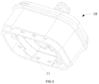
- FIG. 3 is a schematic structural diagram of an atomizer sleeve involved in the embodiment of FIG. 1 from another visual angle;
- FIG. 4 is a schematic structural diagram of an axial section of an atomizer with a detachable atomizer core provided in the embodiments after assembling;
- FIG. 5 is an exploded schematic structural diagram of an atomizer with a detachable atomizer core provided in the embodiments before assembling;
- FIG. 6 is a schematic structural diagram of a base involved in the embodiment of FIG. 1 ;
- FIG. 7 is a schematic structural diagram of a locked state of a sliding latch and an atomizer core provided in the embodiments;
- FIG. 8 is a schematic structural diagram of an unlocked state of the sliding latch and the atomizer core in the embodiment of FIG. 7 ;
- FIG. 9 is a schematic structural diagram of an atomizer core and a seat body provided in the embodiment after assembling
- FIG. 10 is a schematic structural diagram of a sliding latch provided in the embodiments.
- FIG. 11 is a schematic structural diagram of the atomizer core in the embodiment of FIG. 9 after it is assembled with a seat body and a bottom cap;
- FIG. 12 is a schematic structural diagram of a sliding damping member provided in another embodiment
- FIG. 13 is a schematic structural diagram of a sliding damping member provided in a further embodiment.
- FIG. 14 is a schematic structural diagram of an electronic cigarette provided in the embodiments.
- the structure of the foregoing atomizer with the detachable atomizer core and its convenient assembling and disassembling principle will be further described below with specific embodiments.
- the atomizer with a detachable atomizer core disclosed in the present disclosure is mainly suitable for electronic cigarette products. Of course, it can also be used in liquid drug composition volatilization devices or other aromatic composition releasing devices based on the same atomization function.
- an electronic flat cigarette product is taken as an example for description.
- the appearance shape is the shape of a flat cigarette, but it is not limited to this specific situation, and technical personnel can make changes based on this shape during implementation.
- An atomizer with a detachable atomizer core is implemented by means of down core replacement, and is structurally composed of an atomizer sleeve, an atomizer core provided in the atomizer sleeve, and a movable fixed supporting structure, mainly based on the overall design and an assembling connection method.
- a specific detailed structural design and a connection method for an electronic flat cigarette can refer to the accompanying drawings and the following descriptions.
- FIG. 1 is a schematic structural diagram of an atomizer 100 with a detachable atomizer core shown in one embodiment of the present disclosure.
- FIG. 1 shows an overall appearance after combination and assembling.
- the outermost layer of component shown includes a columnar hollow atomizer sleeve 10 , and a mouth piece cap 20 mounted on the atomizer sleeve 10 along an axial direction.
- An atomizer assembly for atomizing smoking oil is mounted in the atomizer sleeve 10 .
- the smoking oil is output from the mouth piece cap 20 for smoking by a smoker after being atomized.
- the structure of the atomizer sleeve 10 refers to what is shown in FIG. 2 and FIG. 3 .
- FIG. 2 and FIG. 3 are respectively schematic structural diagrams of the atomizer sleeve 10 in the embodiment at two visual angles.
- the head and tail ends of the atomizer sleeve 10 are respectively provided with air inlets 11 (in the figure, the lower end is opened) and an air outlet 12 . Cyclic air flow circulation is formed inside the atomizer in combination with the hollow structure inside the atomizer sleeve 10 .
- the air inlet 11 (used for inputting air into the atomizer) can directly or indirectly communicate with external atmosphere, and the air outlet 12 (used for outputting smoking oil aerosol from the atomizer) can also directly or indirectly communicate with the mouth piece cap 20 of the electronic cigarette, so that a customer can smoke the smoking oil aerosol formed in the atomizer through an air flow generated by the mouth piece cap 20 .
- an opening in the lower end of the atomizer sleeve 10 is used as the air inlet 11 used in this embodiment; and furthermore, the space in this opening can also be used to accommodate internal various components and assemble other assemblies (such as a battery pack) of the electronic cigarette.
- a suitable air inlet hole may also be independently formed, without using the opening in the lower end in the embodiment.
- the atomizer sleeve 10 is similar to a hollow cylindrical structure.
- the atomizer sleeve 10 also selects a matching appearance shape with reference to the flat cigarette according to the flatly cylindrical characteristics of the electronic flat cigarette product.
- FIG. 4 is a schematic structural diagram of an axial section of the atomizer 100 with a detachable atomizer core provided in the above embodiment after assembling.
- a smoke passage 13 is provided in the atomizer sleeve 10 along the axial direction and is used for conveying the atomized smoking oil aerosol.
- the smoke passage 13 is connected to the air outlet 12 at the upper end and to an assembly of atomizer core 30 for producing the smoking oil aerosol at the lower end, so as to convey the smoking oil aerosol produced by the assembly of atomizer core 30 to a mouth piece for smoking by the smoker.
- an oil storage chamber 14 for storing smoking oil is formed in a hollow portion between the outer side wall of the smoke passage 13 and the inner side wall of the atomizer sleeve 10 . Fibrous matters for storing the smoking oil or other materials with micropores are usually provided in the oil storage chamber 14 , such as oil storage cotton and fibrous sponge body that are often used in the prior art.
- FIG. 5 is an exploded schematic structural diagram of the atomizer 100 with a detachable atomizer core provided in the embodiments before the various portions are assembled.
- the axially disposed atomizer core 30 is mounted below the smoke passage 13 along the axial direction in the atomizer sleeve 10 .
- the assembly of atomizer core 30 is a whole after the various components are assembled, and includes a hollow columnar porous body 31 for absorbing the smoking oil, and a heating wire 32 mounted on the inner surface of the hollow columnar porous body 31 .
- the porous body 31 itself has a micropore structure and a micropore passage, so that it can absorb the smoking oil stored in the oil storage chamber 14 by means of capillary infiltration, and then convey the smoking oil to the heating wire 32 provided on the inner surface for heating and atomization to produce the aerosol.
- the produced aerosol is then conveyed from the smoke passage 13 to the mouth piece cap 20 for outputting and smoked by the smoker.
- the porous structure provided inside the porous body 31 is an open pore structure.
- a porous ceramic body, a kieselguhr porous body, or a porous quartz glass body, and the like can be used.
- its outer surface is used as an oil absorption surface for absorbing the smoking oil
- its inner surface is used as an atomization surface for mounting the heating wire 32 for atomization.
- Micropores inside realize conveying of the smoking oil from the oil absorption surface to the atomization surface.
- the structure of the heating wire 32 used in this embodiment is a wire and net combination. In addition to a filamentous heating portion, heating portions disposed into a grid are also embedded, so that the heating area and the heating uniformity are improved, and atomization of the smoking oil is more uniform.
- the detachable atomizer core structure of the embodiment of the present disclosure can be applicable to various atomizers of similar structures, and is not limited to the type shown in the figure.
- the atomizer core 30 of the embodiment shown in figure is formed by providing the heating wire 32 on the inner surface of the hollow porous body 31 .
- the atomizer core 30 may also be an external heating type formed by providing the heating wire 32 on the outer surface of the porous body 31 , so that an oil guiding pipeline can be correspondingly provided on the atomizer sleeve 10 to guide the smoking oil in the oil storage chamber 14 to the porous body 31 , and the smoking oil is atomized by the heating wire 32 provided on the outer surface.
- the lower end of the oil storage chamber 14 is provided with a sealing supporting assembly 50 along the axial direction of the atomizer sleeve 10 .
- the sealing supporting assembly 50 can seal the lower end of the oil storage chamber 14 to enable its inside to be a closed chamber to prevent leakage of the smoking oil; and on the other hand, the sealing supporting assembly can be used to support and fixing the detachable mounting of the atomizer core 30 .
- the appearance of the base 51 can be seen from the figure, which adopts a shape design adapting to the lower end of the atomizer sleeve 10 .
- the center of the base 51 is provided with a through hole 511 opposite to the atomizer core 30 ; and based on the purpose of taking out the atomizer core 30 from the atomizer sleeve 10 for replacement and the common design knowledge, the size of the through hole 511 should be slightly greater than the sectional diameter of the atomizer core 30 , so that the atomizer core 30 can penetrate through the through hole 511 and be taken out. Referring to FIG.
- the through hole 511 can also correspondingly include a first through hole portion 511 a located on the seat body 510 , and a second through hole portion 511 b on the bottom cap 520 ; and the first through hole portion 511 a and the second through hole portion 511 b are oppositely disposed to jointly form the whole intact through hole 511 .
- the sealing supporting assembly 50 further includes a sliding latch 52 arranged on the base 51 .
- the sliding latch 52 is used for locking/unlocking the atomizer core 30 , so that the atomizer core 30 is unlocked to be movably taken out when it needs to be taken out, and the atomizer core 30 is fastened in the atomizer sleeve 10 when it does not need to be taken out.
- the sliding latch 52 is slidably mounted on the base 51 , and the base 51 is correspondingly provided with two sliding positions along a sliding direction of the sliding latch 52 .
- FIG. 7 and FIG. 8 are respectively schematic structural diagrams of a locked state and an unlocked state of the sliding latch 52 and an atomizer core 30 .
- the sliding latch 52 slides along the direction A to be separated from the atomizer core 30 as shown in FIG. 8 . That is, when the siding latch 52 is in the second sliding position, the sliding latch 52 and the atomizer core 30 are unlocked and separated from each other, and the atomizer core 30 in a movable state can be taken out from the through hole 511 of the base 51 along the direction B shown in FIG. 7 .
- the atomizer core 30 can penetrate through the through hole 511 and be taken out, but it is relatively difficult to take out the atomizer core 30 without an external force when the atomizer core is removable.
- the atomizer sleeve 10 needs to be downwards shook with a hand to pour the atomizer core 30 out of the atomizer sleeve 10 , which is inconvenient to operate; and on the other hand, a large amount of the smoking oil attached on the atomizer core 30 and in the atomization chamber 14 will leak by the pour-out method, which is not sanitary and inconvenient to clean.
- the atomizer core 30 is additionally provided with a driving member 33 .
- the driving member 33 is a linear spring in the optimal embodiments shown in FIG. 4 , FIG. 5 and FIG. 9 , i.e., a second linear spring.
- FIG. 9 is a schematic structural diagram of an atomizer core and a seat body provided in the embodiment after assembling.
- the driving member 33 is to apply an outward driving thrust from the inside to the atomizer core 30 .
- the atomizer core 30 is pushed out of the inside from the through hole 511 after it becomes a movable state, thereby facilitating the replacement operation.
- the driving member 33 is mounted above the atomizer core 30 along the axial direction when it is the linear spring, with its lower end connected to the atomizer core 30 and its upper end fixedly connected to the inner wall of the atomizer sleeve 10 .
- the sliding latch 52 and the atomizer core 30 are locked and fixed after the atomizer core 30 is normally mounted, and at this time, the driving member 33 is in a compressed state; and after the sliding latch 52 and the atomizer core 30 are unlocked, the driving member 33 is released from the compressed state to generate a thrust to push the atomizer core 30 out of the through hole 511 along the axial direction.
- the above linear spring is the most convenient implementation mode of the driving member 33 .
- technical personnel can also replace it by, for example, an elastic damper or various push devices (a feasible electric push rod and the like) that can realize relevant functions, and a corresponding method is used for performing installation and implementation.
- the sliding latch 52 is provided with a snap-in portion 521
- the atomizer core 30 is correspondingly provided with a snap-in opening 34 (the snap-in opening 34 can be either independently provided or adopt a slot formed between all the assemblies of the atomizer core during assembling); a sliding operation is performed on the sliding latch 52 to cause the snap-in portion 521 to snap in the snap-in opening 34 , thereby realizing sliding locking; and when unlocking is needed, the snap-in portion 521 slides to be separated from the snap-in opening along the direction of the arrow A in FIG. 7 to realize an unlocking operation.
- the base 51 is provided with a guiding groove 53 , and the sliding latch 52 is then mounted in the guiding groove 53 .
- the guiding groove 53 can guide the sliding of the sliding latch 52 to make the sliding process smooth; and on the other hand, the guiding groove 53 can provide an assembling space for the sliding latch 52 .
- FIG. 10 is a schematic structural diagram of the sliding latch provided in the embodiment.
- the sliding latch 52 includes a sliding portion 522 and a snap-in portion 521 .
- the sliding portion 522 is used to realize sliding fit with the guiding groove 53 .
- the sliding portion 522 has an anti-slip rough surface 5221 exposed outside the base 51 .
- the surface pressed by finger of the sliding portion 522 adopts the design of the anti-slip rough surface 5221 , such as a concave-convex tooth surface in FIG. 10 . Therefore, the operation that the user presses the rough surface for sliding with the finger can be smooth and stable.
- the surface pressed by finger is used to enable the user to press the sliding latch 52 with the finger to slide the sliding latch, so that the surface pressed by finger is exposed out of the base 51 , which is convenient for finger contact and sliding pressing.
- a sliding damping member 54 is also provided between the base 51 and the sliding latch 52 .
- the sliding damping member 54 can be as shown in the figure in one implementation mode, i.e., a damping spring. It can also be seen from the figure that the damping spring is also a linear spring, i.e., a first linear spring that is disposed along a sliding direction and connected to the sliding latch 52 at one end and to the base 51 at the other end.
- a damping force is generated by means of an elastic force in the sliding process of the sliding latch 52 .
- the sliding damping member 54 is mounted in the guiding groove 53 when it is the linear spring. Assembling along the sliding direction is convenient and stable.
- the sliding damping member can be installed according to an actual situation if other torsional springs, or dish elastic sheets, or other devices similar to the sliding damping member are used.
- FIG. 12 and FIG. 13 are respectively schematic structural diagrams of the sliding damping member in another two variant implementations.
- the present disclosure further provides a sliding damping member 54 of another implementation mode.
- the sliding damping member 54 includes a first magnetic body 541 provided on the sliding latch 52 , and a second magnetic body 542 provided on the base 51 ; and the second magnetic body 542 is magnetically connected to the first magnetic body 541 when the sliding latch 52 is in the first sliding position.
- the sliding damping member 54 further includes a third magnetic body 543 that can be provided in the following two method, specifically:
- a new atomizer core 30 needs to be plugged into the atomizer sleeve 10 from the through hole 511 along an opposite direction of the arrow B in FIG. 7 , and snaps in the snap-in portion 521 .
- the snap-in portion 521 is correspondingly provided with or correspondingly has a guiding slope 5211 .
- the inclination direction of the guiding slope 5211 is slantways set along the snap-in sliding direction of the snap-in portion 521 towards the atomizer sleeve 10 .
- the guiding slope 5211 should be located on a surface of the snap-in portion 521 opposite to the lower surface of the base 51 according to what is shown in the figure and functional descriptions, instead of being located on a surface opposite to the atomizer sleeve 10 .
- the atomizer when an atomizer product is applied to an electronic flat cigarette product, the atomizer needs to be connected to a battery pack of the electronic cigarette at the lower end through axial assembling, so that the base 51 is further provided with a magnetic connector 55 .
- the magnetic connectors 55 have a plurality of functions in the embodiment of the present disclosure. One of the functions is to connect and lock the seat body 510 to the bottom cap 520 , so that the seat body 510 and the bottom cap 520 are in fastened connection to form the base 51 , thereby facilitating the assembling during connection of the atomizer to a power supply assembly of the electronic cigarette.
- the magnetic connectors 55 can adopt magnets/or iron pillars and other materials. In this method, the magnetic connectors 55 can magnetically cooperate with and magnetically attract another structural member sequentially provided on the power supply assembly of the electronic cigarette, thereby facilitating installation on and aligning connection to the electronic cigarette.
- the portions of the oil storage chamber 14 connected to all the other components may leak the smoking oil, so all the joints are provided with sealing members that respectively refer to FIG. 2 , FIG. 5 and FIG. 9 , specifically including a first sealing member 61 provided at the joint between the base 51 and the oil storage chamber 14 , a second sealing member 62 provided between the atomizer core 30 and the base 51 , and a third sealing member 63 provided between the air outlet 11 of the atomizer sleeve 10 and the mouth piece cap 20 .
- the upper end of the atomization chamber 14 is provided with an oil injection opening for adding smoking oil (in FIG. 2 , the oil injection opening has been covered by a patch 15 , so that it is not marked independently), and the patch 15 for opening and closing the oil injection opening at the surface opposite to the mouth piece cap 20 .
- the patch 15 is provided with a taphole 151 corresponding to the oil injection opening. The taphole is opened if oil injection is necessary; and the taphole 151 is closed if oil injection is not necessary.
- the atomizer core is locked and unlocked by means of sliding of the sliding latch, so that replacement of the atomizer core is realized in combination with the through hole in the base through a down core replacement method, without affecting variations of other components.
- This structure is simple, fast and sanitary, and does not leak oil.
- the embodiment of the present disclosure further provides an electronic cigarette 1000 .
- the above atomizer 100 with the detachable atomizer core can be combined with a power supply assembly 210 , a control circuit and the like of the electronic cigarette 1000 to form a complete electronic cigarette product, wherein the power supply assembly 210 is used for supplying power to the atomizer.
- the electronic cigarette product including the above atomizer with the detachable atomizer core of the present invention
- the smoking oil cannot flow out, and the atomizer core can automatically pop out through sliding of the sliding latch; during mounting of the atomizer core, the atomizer core is plugged according to the direction, so that the operation is simple; and the atomizer is sanitary and free of oil leakage.
Landscapes
- Disinfection, Sterilisation Or Deodorisation Of Air (AREA)
- Special Spraying Apparatus (AREA)
Applications Claiming Priority (3)
| Application Number | Priority Date | Filing Date | Title |
|---|---|---|---|
| CN201811299420.9A CN109303355A (zh) | 2018-11-02 | 2018-11-02 | 可拆雾化芯的雾化器及电子烟 |
| CN201811299420.9 | 2018-11-02 | ||
| PCT/CN2019/114420 WO2020088539A1 (zh) | 2018-11-02 | 2019-10-30 | 可拆雾化芯的雾化器及电子烟 |
Publications (2)
| Publication Number | Publication Date |
|---|---|
| US20220015422A1 US20220015422A1 (en) | 2022-01-20 |
| US11937635B2 true US11937635B2 (en) | 2024-03-26 |
Family
ID=65222796
Family Applications (1)
| Application Number | Title | Priority Date | Filing Date |
|---|---|---|---|
| US17/290,299 Active 2041-04-08 US11937635B2 (en) | 2018-11-02 | 2019-10-30 | Atomizer having detachable atomizing core and electronic cigarette |
Country Status (4)
| Country | Link |
|---|---|
| US (1) | US11937635B2 (zh) |
| EP (1) | EP3874979B1 (zh) |
| CN (1) | CN109303355A (zh) |
| WO (1) | WO2020088539A1 (zh) |
Families Citing this family (20)
| Publication number | Priority date | Publication date | Assignee | Title |
|---|---|---|---|---|
| CN109303355A (zh) * | 2018-11-02 | 2019-02-05 | 深圳市合元科技有限公司 | 可拆雾化芯的雾化器及电子烟 |
| CN109770439A (zh) * | 2019-03-25 | 2019-05-21 | 云南中烟工业有限责任公司 | 一种微流道电子烟雾化芯片及其制备方法 |
| CN111602860A (zh) * | 2019-06-29 | 2020-09-01 | 深圳市艾维普思科技有限公司 | 一种电子烟 |
| CN111067149B (zh) * | 2019-12-31 | 2023-12-15 | 深圳市吉迩科技有限公司 | 雾化器、气溶胶产生装置及采用该气溶胶产生装置的吸合方法 |
| EP4099856B1 (en) | 2020-02-04 | 2025-02-26 | Juul Labs, Inc. | Aerosol dispensing device with disposable container |
| CN111567891A (zh) * | 2020-04-24 | 2020-08-25 | 同济大学 | 一种具有雾化结构的电子烟 |
| CN111671159B (zh) * | 2020-07-27 | 2024-06-11 | 凡品思(深圳)科技有限公司 | 推动组件及电子烟 |
| CN111838763B (zh) * | 2020-07-31 | 2024-05-28 | 绿烟实业(深圳)有限公司 | 雾化器组件及电子烟 |
| CN111938198A (zh) * | 2020-08-24 | 2020-11-17 | 深圳市吉迩科技有限公司 | 一种新型加油密封装置及气溶胶产生装置 |
| CN111990699B (zh) * | 2020-09-29 | 2025-10-17 | 重庆中烟工业有限责任公司 | 一种可自动旋转的电子烟具 |
| CN112293803A (zh) * | 2020-10-15 | 2021-02-02 | 深圳市艾维普思科技有限公司 | 电子雾化装置及其雾化组件 |
| CN112425822A (zh) * | 2020-10-15 | 2021-03-02 | 深圳市艾维普思科技有限公司 | 一种电子雾化装置及气溶胶发生器 |
| CN112545056B (zh) * | 2020-11-16 | 2025-01-14 | 深圳市吉迩科技有限公司 | 一种雾化芯锁止方法及其装置、气溶胶产生装置 |
| CN112841723A (zh) * | 2020-12-31 | 2021-05-28 | 深圳市艾维普思科技有限公司 | 一种电子雾化装置及气溶胶发生器 |
| CN115500554B (zh) * | 2021-06-07 | 2025-02-14 | 深圳市卓力能技术有限公司 | 雾化芯、雾化设备主体及雾化设备 |
| CN217161080U (zh) * | 2021-12-30 | 2022-08-12 | 江门摩尔科技有限公司 | 雾化器、密封件及电子雾化装置 |
| CN114766733A (zh) * | 2022-06-08 | 2022-07-22 | 深圳麦克韦尔科技有限公司 | 雾化结构及电子雾化装置 |
| CN115177027A (zh) * | 2022-08-15 | 2022-10-14 | 深圳市吉迩科技有限公司 | 便于拆卸的雾化器及雾化设备 |
| USD1032081S1 (en) * | 2022-08-16 | 2024-06-18 | Huizhou Happy Vaping Technology Limited | Electronic cigarette vaporizer |
| CN115844065A (zh) * | 2022-12-30 | 2023-03-28 | 深圳市吉迩科技有限公司 | 一种雾化器及气溶胶发生装置 |
Citations (24)
| Publication number | Priority date | Publication date | Assignee | Title |
|---|---|---|---|---|
| US4676408A (en) * | 1984-06-15 | 1987-06-30 | Teleplastics Industries S.A. | Case in two portions assembled by a latching device, notably a refillable sprayer |
| US20160050975A1 (en) | 2014-08-21 | 2016-02-25 | R.J. Reynolds Tobacco Company | Aerosol Delivery Device Including a Moveable Cartridge and Related Assembly Method |
| WO2016029344A1 (zh) | 2014-08-25 | 2016-03-03 | 惠州市吉瑞科技有限公司 | 一种电子烟 |
| CN205321209U (zh) | 2015-12-29 | 2016-06-22 | 深圳睿思奇科技开发有限公司 | 电子烟及其雾化芯固定结构 |
| CN205321203U (zh) | 2015-09-02 | 2016-06-22 | 深圳市亿斯恩科技有限公司 | 一种雾化芯可更换的雾化器 |
| US20160353798A1 (en) | 2013-11-29 | 2016-12-08 | Kimree Hi-Tech Inc. | Electronic cigarette device |
| CN205794808U (zh) | 2016-06-16 | 2016-12-14 | 深圳市新宜康科技有限公司 | 新型扁薄电子烟雾化器及扁薄电子烟 |
| CN205962831U (zh) | 2016-04-29 | 2017-02-22 | 湖南中烟工业有限责任公司 | 一种雾化器 |
| US20170071260A1 (en) * | 2015-11-25 | 2017-03-16 | Shenzhen First Union Technology Co., Ltd. | Liquid supply, atomizer and electronic cigarette having same |
| US20170172207A1 (en) | 2014-02-12 | 2017-06-22 | Kimree Hi-Tech Inc. | Electronic cigarette |
| CN206453250U (zh) | 2017-01-13 | 2017-09-01 | 常州市派腾电子技术服务有限公司 | 一种雾化器及电子烟 |
| CN206565292U (zh) | 2016-10-31 | 2017-10-20 | 深圳市合元科技有限公司 | 可更换雾化芯的雾化器及电子烟 |
| US20180049470A1 (en) | 2016-06-28 | 2018-02-22 | Shenzhen Smoore Technology Limited | Electronic cigarette and atomizer device and atomizer assembly thereof |
| US20180084832A1 (en) * | 2016-09-26 | 2018-03-29 | Shenzhen First Union Technology Co., Ltd. | Electronic cigarette |
| US20180116295A1 (en) * | 2015-07-14 | 2018-05-03 | Changzhou Jwei Intelligent Technology Co., Ltd. | Atomizer and electronic cigarette thereof |
| US20180255836A1 (en) * | 2015-11-19 | 2018-09-13 | Changzhou Jwei Intelligent Technology Co., Ltd. | Child-proof atomizer and electronic cigarette having child-proof atomizer |
| CN108634385A (zh) | 2018-05-24 | 2018-10-12 | 刘团芳 | 一种可从顶部侧面注油的雾化器 |
| CN208002103U (zh) | 2018-02-05 | 2018-10-26 | 深圳市新宜康电子技术有限公司 | 一次性烟弹的雾化发生装置 |
| CN109303355A (zh) | 2018-11-02 | 2019-02-05 | 深圳市合元科技有限公司 | 可拆雾化芯的雾化器及电子烟 |
| US20190075846A1 (en) * | 2016-05-06 | 2019-03-14 | Changzhou Jwei Intelligent Technology Co., Ltd. | Atomizing device and electronic cigarette thereof |
| US20190098931A1 (en) * | 2016-03-24 | 2019-04-04 | Nicoventures Holdings Limitted | Mechanical connector for electronic vapour provision system |
| US20190239565A1 (en) * | 2018-02-02 | 2019-08-08 | Changzhou Patent Electronic Technology Co., LTD | Battery assembly for electronic cigarette and electronic cigarette |
| CN209376683U (zh) | 2018-11-02 | 2019-09-13 | 深圳市合元科技有限公司 | 可拆雾化芯的雾化器及电子烟 |
| US11785988B2 (en) * | 2020-10-16 | 2023-10-17 | Rai Strategic Holdings, Inc. | Security features for aerosol generation device |
Family Cites Families (9)
| Publication number | Priority date | Publication date | Assignee | Title |
|---|---|---|---|---|
| CN203952431U (zh) * | 2014-05-23 | 2014-11-26 | 深圳市合元科技有限公司 | 电子烟用雾化器及电子烟 |
| CN106455693B (zh) * | 2014-04-03 | 2019-03-05 | 吉瑞高新科技股份有限公司 | 电子烟 |
| CN204169057U (zh) * | 2014-04-21 | 2015-02-25 | 惠州市吉瑞科技有限公司 | 一种电子烟 |
| CN204273232U (zh) * | 2014-04-24 | 2015-04-22 | 惠州市吉瑞科技有限公司 | 一种电子烟 |
| CN204722254U (zh) * | 2015-02-28 | 2015-10-28 | 惠州市吉瑞科技有限公司 | 一种雾化组件及电子烟 |
| CN205337599U (zh) * | 2015-10-22 | 2016-06-29 | 深圳麦克韦尔股份有限公司 | 电子烟及其雾化组件和雾化元件 |
| CN205512338U (zh) * | 2015-12-25 | 2016-08-31 | 深圳瀚星翔科技有限公司 | 一种雾化芯及电子烟雾化器 |
| CN206284395U (zh) * | 2016-11-10 | 2017-06-30 | 卓尔悦欧洲控股有限公司 | 一种雾化器及其电子烟 |
| CN207912048U (zh) * | 2017-12-25 | 2018-09-28 | 惠州市吉瑞科技有限公司深圳分公司 | 一种电子烟 |
-
2018
- 2018-11-02 CN CN201811299420.9A patent/CN109303355A/zh active Pending
-
2019
- 2019-10-30 WO PCT/CN2019/114420 patent/WO2020088539A1/zh not_active Ceased
- 2019-10-30 US US17/290,299 patent/US11937635B2/en active Active
- 2019-10-30 EP EP19878088.4A patent/EP3874979B1/en active Active
Patent Citations (24)
| Publication number | Priority date | Publication date | Assignee | Title |
|---|---|---|---|---|
| US4676408A (en) * | 1984-06-15 | 1987-06-30 | Teleplastics Industries S.A. | Case in two portions assembled by a latching device, notably a refillable sprayer |
| US20160353798A1 (en) | 2013-11-29 | 2016-12-08 | Kimree Hi-Tech Inc. | Electronic cigarette device |
| US20170172207A1 (en) | 2014-02-12 | 2017-06-22 | Kimree Hi-Tech Inc. | Electronic cigarette |
| US20160050975A1 (en) | 2014-08-21 | 2016-02-25 | R.J. Reynolds Tobacco Company | Aerosol Delivery Device Including a Moveable Cartridge and Related Assembly Method |
| WO2016029344A1 (zh) | 2014-08-25 | 2016-03-03 | 惠州市吉瑞科技有限公司 | 一种电子烟 |
| US20180116295A1 (en) * | 2015-07-14 | 2018-05-03 | Changzhou Jwei Intelligent Technology Co., Ltd. | Atomizer and electronic cigarette thereof |
| CN205321203U (zh) | 2015-09-02 | 2016-06-22 | 深圳市亿斯恩科技有限公司 | 一种雾化芯可更换的雾化器 |
| US20180255836A1 (en) * | 2015-11-19 | 2018-09-13 | Changzhou Jwei Intelligent Technology Co., Ltd. | Child-proof atomizer and electronic cigarette having child-proof atomizer |
| US20170071260A1 (en) * | 2015-11-25 | 2017-03-16 | Shenzhen First Union Technology Co., Ltd. | Liquid supply, atomizer and electronic cigarette having same |
| CN205321209U (zh) | 2015-12-29 | 2016-06-22 | 深圳睿思奇科技开发有限公司 | 电子烟及其雾化芯固定结构 |
| US20190098931A1 (en) * | 2016-03-24 | 2019-04-04 | Nicoventures Holdings Limitted | Mechanical connector for electronic vapour provision system |
| CN205962831U (zh) | 2016-04-29 | 2017-02-22 | 湖南中烟工业有限责任公司 | 一种雾化器 |
| US20190075846A1 (en) * | 2016-05-06 | 2019-03-14 | Changzhou Jwei Intelligent Technology Co., Ltd. | Atomizing device and electronic cigarette thereof |
| CN205794808U (zh) | 2016-06-16 | 2016-12-14 | 深圳市新宜康科技有限公司 | 新型扁薄电子烟雾化器及扁薄电子烟 |
| US20180049470A1 (en) | 2016-06-28 | 2018-02-22 | Shenzhen Smoore Technology Limited | Electronic cigarette and atomizer device and atomizer assembly thereof |
| US20180084832A1 (en) * | 2016-09-26 | 2018-03-29 | Shenzhen First Union Technology Co., Ltd. | Electronic cigarette |
| CN206565292U (zh) | 2016-10-31 | 2017-10-20 | 深圳市合元科技有限公司 | 可更换雾化芯的雾化器及电子烟 |
| CN206453250U (zh) | 2017-01-13 | 2017-09-01 | 常州市派腾电子技术服务有限公司 | 一种雾化器及电子烟 |
| US20190239565A1 (en) * | 2018-02-02 | 2019-08-08 | Changzhou Patent Electronic Technology Co., LTD | Battery assembly for electronic cigarette and electronic cigarette |
| CN208002103U (zh) | 2018-02-05 | 2018-10-26 | 深圳市新宜康电子技术有限公司 | 一次性烟弹的雾化发生装置 |
| CN108634385A (zh) | 2018-05-24 | 2018-10-12 | 刘团芳 | 一种可从顶部侧面注油的雾化器 |
| CN109303355A (zh) | 2018-11-02 | 2019-02-05 | 深圳市合元科技有限公司 | 可拆雾化芯的雾化器及电子烟 |
| CN209376683U (zh) | 2018-11-02 | 2019-09-13 | 深圳市合元科技有限公司 | 可拆雾化芯的雾化器及电子烟 |
| US11785988B2 (en) * | 2020-10-16 | 2023-10-17 | Rai Strategic Holdings, Inc. | Security features for aerosol generation device |
Also Published As
| Publication number | Publication date |
|---|---|
| EP3874979A4 (en) | 2022-05-04 |
| WO2020088539A1 (zh) | 2020-05-07 |
| US20220015422A1 (en) | 2022-01-20 |
| EP3874979A1 (en) | 2021-09-08 |
| CN109303355A (zh) | 2019-02-05 |
| EP3874979B1 (en) | 2023-04-26 |
Similar Documents
| Publication | Publication Date | Title |
|---|---|---|
| US11937635B2 (en) | Atomizer having detachable atomizing core and electronic cigarette | |
| CN107205487B (zh) | 一种雾化器 | |
| CN207011680U (zh) | 雾化器及其电子烟 | |
| CN205196997U (zh) | 用于电子烟的储液器以及雾化器和电子烟 | |
| CN203952431U (zh) | 电子烟用雾化器及电子烟 | |
| CN204169057U (zh) | 一种电子烟 | |
| CN211746942U (zh) | 上盖组件、雾化器及其气溶胶发生装置 | |
| EP3569074A1 (en) | Cigarette cartridge, atomizer and electronic cigarette thereof | |
| CN105380299A (zh) | 雾化器及其电子烟 | |
| CN209376683U (zh) | 可拆雾化芯的雾化器及电子烟 | |
| WO2016041140A1 (zh) | 一种电子烟 | |
| CN113925218B (zh) | 雾化器及电子雾化装置 | |
| US12382994B2 (en) | Heat-not-burn tobacco device | |
| CN206687176U (zh) | 雾化器及其电子烟 | |
| CN203563696U (zh) | 无棉电子烟的雾化装置 | |
| CN210137816U (zh) | 雾化器及其电子烟 | |
| WO2018133370A1 (zh) | 烟弹、雾化器及其电子烟 | |
| CN205865992U (zh) | 一种改进的电子雾化烟 | |
| CN207519629U (zh) | 雾化器及电子烟 | |
| CN207767544U (zh) | 雾化器及电子烟 | |
| CN205266970U (zh) | 雾化器及其电子烟 | |
| CN210017900U (zh) | 上盖组件、雾化器及其电子烟 | |
| EP3871541B1 (en) | Cartridge and electronic cigarette | |
| CN212065675U (zh) | 雾化器及气溶胶发生装置 | |
| CN210809300U (zh) | 具有锁油装置的雾化器 |
Legal Events
| Date | Code | Title | Description |
|---|---|---|---|
| AS | Assignment |
Owner name: SHENZHEN FIRST UNION TECHNOLOGY CO., LTD., CHINA Free format text: ASSIGNMENT OF ASSIGNORS INTEREST;ASSIGNORS:ZHAO, XIAOQIANG;YAN, GAOFENG;XU, ZHONGLI;AND OTHERS;REEL/FRAME:056092/0140 Effective date: 20210407 |
|
| FEPP | Fee payment procedure |
Free format text: ENTITY STATUS SET TO UNDISCOUNTED (ORIGINAL EVENT CODE: BIG.); ENTITY STATUS OF PATENT OWNER: LARGE ENTITY |
|
| FEPP | Fee payment procedure |
Free format text: ENTITY STATUS SET TO SMALL (ORIGINAL EVENT CODE: SMAL); ENTITY STATUS OF PATENT OWNER: LARGE ENTITY |
|
| FEPP | Fee payment procedure |
Free format text: ENTITY STATUS SET TO UNDISCOUNTED (ORIGINAL EVENT CODE: BIG.); ENTITY STATUS OF PATENT OWNER: LARGE ENTITY |
|
| FEPP | Fee payment procedure |
Free format text: ENTITY STATUS SET TO SMALL (ORIGINAL EVENT CODE: SMAL); ENTITY STATUS OF PATENT OWNER: LARGE ENTITY |
|
| STPP | Information on status: patent application and granting procedure in general |
Free format text: DOCKETED NEW CASE - READY FOR EXAMINATION |
|
| FEPP | Fee payment procedure |
Free format text: ENTITY STATUS SET TO UNDISCOUNTED (ORIGINAL EVENT CODE: BIG.); ENTITY STATUS OF PATENT OWNER: LARGE ENTITY |
|
| STPP | Information on status: patent application and granting procedure in general |
Free format text: NOTICE OF ALLOWANCE MAILED -- APPLICATION RECEIVED IN OFFICE OF PUBLICATIONS |
|
| STCF | Information on status: patent grant |
Free format text: PATENTED CASE |