US11926999B2 - Outlet for a water armature - Google Patents
Outlet for a water armature Download PDFInfo
- Publication number
- US11926999B2 US11926999B2 US17/275,329 US201917275329A US11926999B2 US 11926999 B2 US11926999 B2 US 11926999B2 US 201917275329 A US201917275329 A US 201917275329A US 11926999 B2 US11926999 B2 US 11926999B2
- Authority
- US
- United States
- Prior art keywords
- outlet
- tube
- another
- fluid channels
- water
- Prior art date
- Legal status (The legal status is an assumption and is not a legal conclusion. Google has not performed a legal analysis and makes no representation as to the accuracy of the status listed.)
- Active, expires
Links
- XLYOFNOQVPJJNP-UHFFFAOYSA-N water Substances O XLYOFNOQVPJJNP-UHFFFAOYSA-N 0.000 title claims abstract description 45
- 239000012530 fluid Substances 0.000 claims abstract description 78
- 230000007704 transition Effects 0.000 claims description 33
- 238000000034 method Methods 0.000 claims description 10
- 238000004519 manufacturing process Methods 0.000 claims description 7
- 239000000463 material Substances 0.000 description 21
- CURLTUGMZLYLDI-UHFFFAOYSA-N Carbon dioxide Chemical compound O=C=O CURLTUGMZLYLDI-UHFFFAOYSA-N 0.000 description 4
- 239000004033 plastic Substances 0.000 description 4
- 229920003023 plastic Polymers 0.000 description 4
- 229910002092 carbon dioxide Inorganic materials 0.000 description 3
- 230000008859 change Effects 0.000 description 3
- 239000004707 linear low-density polyethylene Substances 0.000 description 3
- 229920001296 polysiloxane Polymers 0.000 description 3
- 239000000243 solution Substances 0.000 description 3
- 229910001369 Brass Inorganic materials 0.000 description 2
- HCHKCACWOHOZIP-UHFFFAOYSA-N Zinc Chemical compound [Zn] HCHKCACWOHOZIP-UHFFFAOYSA-N 0.000 description 2
- 239000010951 brass Substances 0.000 description 2
- 230000001419 dependent effect Effects 0.000 description 2
- 230000009969 flowable effect Effects 0.000 description 2
- 239000004700 high-density polyethylene Substances 0.000 description 2
- 239000011701 zinc Substances 0.000 description 2
- 229910052725 zinc Inorganic materials 0.000 description 2
- 229920000491 Polyphenylsulfone Polymers 0.000 description 1
- 229910001229 Pot metal Inorganic materials 0.000 description 1
- 230000008901 benefit Effects 0.000 description 1
- 239000001569 carbon dioxide Substances 0.000 description 1
- 239000003651 drinking water Substances 0.000 description 1
- 235000020188 drinking water Nutrition 0.000 description 1
- 239000000835 fiber Substances 0.000 description 1
- 229920001903 high density polyethylene Polymers 0.000 description 1
- 229940063583 high-density polyethylene Drugs 0.000 description 1
- 238000001746 injection moulding Methods 0.000 description 1
- 235000000396 iron Nutrition 0.000 description 1
- 239000003550 marker Substances 0.000 description 1
- 239000000203 mixture Substances 0.000 description 1
- 230000002093 peripheral effect Effects 0.000 description 1
- 229920012287 polyphenylene sulfone Polymers 0.000 description 1
- 230000008569 process Effects 0.000 description 1
- 229910001220 stainless steel Inorganic materials 0.000 description 1
- 239000010935 stainless steel Substances 0.000 description 1
- 230000008719 thickening Effects 0.000 description 1
Images


Classifications
-
- E—FIXED CONSTRUCTIONS
- E03—WATER SUPPLY; SEWERAGE
- E03C—DOMESTIC PLUMBING INSTALLATIONS FOR FRESH WATER OR WASTE WATER; SINKS
- E03C1/00—Domestic plumbing installations for fresh water or waste water; Sinks
- E03C1/02—Plumbing installations for fresh water
- E03C1/04—Water-basin installations specially adapted to wash-basins or baths
- E03C1/0404—Constructional or functional features of the spout
-
- F—MECHANICAL ENGINEERING; LIGHTING; HEATING; WEAPONS; BLASTING
- F16—ENGINEERING ELEMENTS AND UNITS; GENERAL MEASURES FOR PRODUCING AND MAINTAINING EFFECTIVE FUNCTIONING OF MACHINES OR INSTALLATIONS; THERMAL INSULATION IN GENERAL
- F16L—PIPES; JOINTS OR FITTINGS FOR PIPES; SUPPORTS FOR PIPES, CABLES OR PROTECTIVE TUBING; MEANS FOR THERMAL INSULATION IN GENERAL
- F16L11/00—Hoses, i.e. flexible pipes
- F16L11/22—Multi-channel hoses
-
- E—FIXED CONSTRUCTIONS
- E03—WATER SUPPLY; SEWERAGE
- E03C—DOMESTIC PLUMBING INSTALLATIONS FOR FRESH WATER OR WASTE WATER; SINKS
- E03C1/00—Domestic plumbing installations for fresh water or waste water; Sinks
- E03C1/02—Plumbing installations for fresh water
- E03C1/04—Water-basin installations specially adapted to wash-basins or baths
- E03C1/0411—Taps specially designed for dispensing boiling water
-
- E—FIXED CONSTRUCTIONS
- E03—WATER SUPPLY; SEWERAGE
- E03C—DOMESTIC PLUMBING INSTALLATIONS FOR FRESH WATER OR WASTE WATER; SINKS
- E03C1/00—Domestic plumbing installations for fresh water or waste water; Sinks
- E03C1/02—Plumbing installations for fresh water
- E03C1/04—Water-basin installations specially adapted to wash-basins or baths
- E03C2001/0415—Water-basin installations specially adapted to wash-basins or baths having an extendable water outlet
-
- E—FIXED CONSTRUCTIONS
- E03—WATER SUPPLY; SEWERAGE
- E03C—DOMESTIC PLUMBING INSTALLATIONS FOR FRESH WATER OR WASTE WATER; SINKS
- E03C2201/00—Details, devices or methods not otherwise provided for
- E03C2201/40—Arrangement of water treatment devices in domestic plumbing installations
Definitions
- the invention relates to an outlet for a water armature, a water armature, a method for the production of an outlet for a water armature, and the use of a tube.
- the outlet has to be significantly wider in diameter, which, however, would be disadvantageous, in particular with respect to current design requirements (great degree of design freedom) and due to increased material costs.
- assembly would be significantly more costly, in particular, because several tubes would have to be drawn into the outlet for both options.
- an outlet for a water armature, a water armature, a method for the production of a water armature, and a use of a tube are to be indicated, which at least contribute to being able to conduct more than two fluid flows separately from one another through an outlet of a water armature while also providing the greatest possible design freedom for the outlet.
- the material costs for the outlet should be kept as low as possible and/or the production or assembly of the outlet should be as simple as possible.
- An outlet for a water armature contributes to this purpose with an inlet region and an outlet region, wherein a tube extends from the inlet region to the outlet region through an outlet body and wherein at least three fluid channels are formed which run parallel to one another and separate from one another.
- the solution proposed here contributes in an advantageous manner to more than two fluid flows being able to be conducted separate from one another through an outlet of a water armature.
- Particularly advantageous in this context is that, based on the configuration of the tube with at least three fluid channels that run parallel to one another and separately from one another proposed here, a comparatively high degree of design freedom of the outlet can be made possible.
- the configuration of the tube contributes in particular to a comparatively small outer diameter of the outlet.
- the material costs for the outlet can be kept low.
- the production or assembly of the outlet can be kept as simple as possible, in particular because only one tube must be introduced into the outlet body.
- the inlet region can extend, for example, up to 10 cm along the outlet body, starting from one inlet cross-section of the outlet body (at one of the end faces or end surfaces of the outlet).
- the outlet region may extend (back), for example, up to 10 cm along the outlet body, starting from one outlet cross-section of the outlet body (at the other of the end faces or end surfaces of the outlet body).
- the outlet has one (single) tube.
- the tube extends through the outlet body from the inlet region to the outlet region.
- one single tube or only one tube extends through the outlet body.
- the tube extends at least from one end of the inlet region to a beginning of the outlet region.
- the tube extends preferably through the outlet body in such a way that fluid conducted through the fluid channels does not wet the outlet body, in particular not an inner surface of the outlet body.
- the tube is a multi-lumen tube or multi-lumen tube with at least three lumens.
- the tube is elongated (its length is significantly larger than its diameter).
- the tube is formed in one piece or one part.
- the tube is preferably formed with one of the following materials or a combination thereof: silicone, LLDPE or comparable materials.
- Silicone or comparable materials which usually meet requirements for food, are particularly preferred. These materials should preferably be able to be used in a temperature range from 4° C. to +100° C. and/or in comparison be watertight to gas, such as CO 2 .
- the material LLDPE Linear Low-Density Poly-Ethylene
- This material can usually be used for a temperature range from ⁇ 30° C. to +65° C. and advantageously is already approved for the food industry.
- Silicone tubes usually have (depending on material composition) a range of use from ⁇ 100° C. to +300° C. This material is currently also used, in particular, in the household appliance industry (drink dispensers, coffee machine, electric irons, etc.) for conducting fluids.
- a further advantage consists in the fact that this material is already approved for the food industry, drinking water applications and sanitary applications.
- the outlet also has an outlet body.
- the outlet body preferably has a round, in particular circular outer contour and/or cross-sectional shape (in cross-section). Furthermore, the outlet body preferably has a round, in particular circular inner contour (in cross-section).
- the outlet body is preferably formed in one piece or one part.
- the outlet body is preferably formed from one of the following materials or a combination thereof: plastic, zinc, brass.
- the outlet body can also be produced with respect to materials, for example, from various materials.
- this can be a combination of a plastic water conduit (for example, with HDPE: High-Density Poly-Ethylene; PPSU: Polyphenylene sulfone) and a material including these (for example, die-cast zinc material).
- a plastic water conduit for example, with HDPE: High-Density Poly-Ethylene; PPSU: Polyphenylene sulfone
- a material including these for example, die-cast zinc material.
- brass can also be used.
- the outlet body is produced with a (plastic) injection molding method or a (zinc) die-cast method. Since the fluid channels are formed with the tube, a material can be used for the outlet body in an advantageous manner that does not necessarily have to satisfy the high requirements that are placed on materials for water-conducting surfaces.
- At least three fluid channels that run parallel to one another and separate from one another are formed in the tube.
- the tube cross-section surface between the fluid channels and/or outside the fluid channels is completely filled with the material of the tube.
- the tube cross-section area relates, in particular, to a cross-sectional plane that is perpendicular to a center line of the tube. At least three, four, or even five fluid channels that run parallel to one another and separate from one another are preferably formed in the tube.
- the fluid channels preferably extend at least in sections, in particular, they preferably extend completely through the tube.
- the fluid channels extend from one of the end faces or end surfaces of the tube to the other end face or end surface of the tube.
- the fluid channels are normally closed on the circumference. In other words, this means, in particular, that a fluid flow cannot leave the respective fluid channel between the two end faces or end surfaces of the tube, in particular not in the radial direction.
- At least two of the fluid channels extend along a common separating wall.
- adjacent fluid channels always extend along a common separating wall.
- at least one web can be formed in the tube to separate the fluid channels.
- the web can, for example, form a common separating wall.
- the web or the separating wall are preferably aligned radially.
- a common separating wall can have an arcuate cross-sectional shape.
- the cross-sectional shape relates in this context, in particular, to a cross-sectional plane that is perpendicular to a center line of the tube.
- At least one of the fluid channels has a round, in particular circular, cross-sectional shape.
- the cross-sectional shape relates, in particular, to a cross-sectional plane that is perpendicular to a center line of the tube.
- the most preferable is that at least two or even three of the fluid channels have a round, in particular circular, cross-sectional shape.
- At least one of the fluid channels preferably has a cross-sectional shape of a ring sector, in particular of a circular ring sector.
- the cross-sectional shape relates in this context, in particular, to a cross-sectional plane that is perpendicular to a center line of the tube.
- the most preferable is that at least two or even three of the fluid channels have the cross-sectional shape of a ring sector, in particular of a circular ring sector.
- At least two of the fluid channels are arranged so to be distributed over a circumference of the tube (or spaced at a distance from one another along the circumference).
- the at least three fluid channels are arranged so as to be distributed over the circumference of the tube, in particular evenly arranged.
- At least two of the fluid channels are arranged radially one after another.
- the radius relates in this context, in particular, to a center line of the tube.
- At least one connecting piece be arranged in the inlet region or the outlet region.
- a connecting piece is arranged at least in the outlet region.
- the connecting piece can be formed as a cylinder (i.e., its length is greater than its diameter) or as a plate (i.e., its diameter is greater than its length).
- At least three fluid paths are formed in the connecting piece that pass through the connecting piece.
- the fluid paths lead from a first end face or end surface to a second end face or end surface of the connecting piece.
- each of the fluid paths is assigned (specifically) to one of the three fluid channels.
- At least one transition piece is arranged between the tube and the connecting piece.
- the transition piece can be configured to be partially inserted, in particular plugged into one of the fluid channels of the tube and/or into one of the fluid paths of the connecting piece.
- the transition piece is able to be inserted or is inserted with a first end into one of the fluid channels of the tube and with a second end of the fluid paths of the connecting piece.
- the first end and the second end of the transition piece are arranged in particular opposite one another and facing away from one another.
- a fluid path usually extends through the transition piece.
- the fluid path extends in particular from the first end (from a first end face or end surface) to the second end (of a second end face or end surface) of the transition piece.
- the transition piece can have an outer shape that is conical, at least in sections.
- the fluid path through the transition piece can be formed, at least in sections, conically.
- a cross-section of the fluid path that can be flowed through can taper or expand at least in sections (continuously).
- a change of the cross-section of the fluid path through the transition piece that can be flowed through can advantageously contribute to influencing the fluid flow at the end of a fluid channel, in particular to slowing or accelerating the flow velocity.
- the transition pieces are arranged adjacent to one another between the tube and the connecting piece.
- the transition pieces are arranged adjacent to one another here in a cross-sectional area.
- the cross-sectional area relates, in particular, to a cross-sectional plane that is perpendicular to a center line of the tube and/or the connecting piece.
- At least three transition pieces are preferably arranged adjacent to one another between the tube and the connecting piece.
- each of the transition pieces is assigned to one (specific) of the three fluid channels of the tube. In other words, this means, in particular, that each of the fluid channels can have its (own) transition piece assigned to it.
- a fluid path extends through each of the transition pieces.
- At least one of the transition pieces preferably has a cross-section of the fluid path through the transition piece that can be flowed through, which differs from a cross-section of the fluid path through which another of the transition pieces can flow.
- at least one of the transition pieces has a change in the flowable cross-section of the fluid path through the transition piece, which differs from a change in the flowable cross-section of the fluid path through another of the transition pieces. This advantageously allows the transition pieces to be able to influence the fluid flows differently.
- the tube can be marked, for example, with a marking (recognizable from the outside) in order to advantageously enable the channels in the interior to be assigned to other components (for example, connecting pieces, threaded connections).
- This marking can comprise, for example, a marker thread and/or at least a thickening in the shape of a dot on the inlet side and/or outlet side of the tube.
- the marking can be used to avoid confusing the channels.
- a water armature comprising an outlet as proposed here.
- the water armature can be, for example, a sink armature, a kitchen armature or a washbasin.
- the water armature further has a mixing device for mixing cold water and hot water.
- the outlet is usually mounted on an outlet side of the mixing device.
- the tube introduced here can also be used together with a water armature with a removable sprayer or in case of a pull-out variant of a water armature.
- a method for producing an outlet for a water armature comprising at least the following steps:
- the indicated sequence of the steps a), b) and c) usually applies in a regular operational process. Moreover, the steps a), b) and c), in particular the steps a) and b), can be carried out at least in part in parallel or even simultaneously. This is preferably used to produce an outlet for a water armature proposed here.
- the tube is preferably drawn in or into the outlet body in step c).
- a tube in which at least three fluid channels that run parallel to one another and separate from one another are formed for separately conducting fluid flows through an outlet of a water armature.
- the tube is preferably used for separately conducting at least three fluids (or media) and/or three fluid flows through an outlet of a water armature.
- At least two of the three fluids or fluid flows can differ from one another in this context, in particular with respect to their temperature and/or their gas content, such as carbon dioxide content or their flow velocity.
- FIG. 1 an exemplary embodiment of a water armature proposed here
- FIG. 2 a sectional, detailed view of the embodiment according to FIG. 1 ,
- FIG. 3 a further sectional, detailed view of the embodiment according to FIG. 1 ,
- FIG. 4 a further sectional, detailed view of the embodiment according to FIG. 1 ,
- FIG. 5 a - e exemplary embodiments of a tube, as it may be used in the outlet proposed here, each in a front view.
- FIG. 6 a perspective view of the tube, according to FIG. 5 b,
- FIG. 7 a further perspective view of the tube according to FIG. 5 b
- FIG. 8 a sectional, detailed view of an exemplary embodiment of the outlet proposed here
- FIG. 9 a sectional, detailed view of a further exemplary embodiment of an outlet proposed here,
- FIG. 10 a further sectional, detailed view of the embodiment according to FIG. 9 ,
- FIG. 11 a further sectional, detailed view of the embodiment according to FIG. 9 ,
- FIG. 12 a sectional, detailed view of a further exemplary embodiment of an outlet proposed here,
- FIG. 13 a further sectional, detailed view of the embodiment according to FIG. 12 ,
- FIG. 14 a further sectional, detailed view of the embodiment according to FIG. 12 ,
- FIG. 15 exemplary embodiments of a transition piece, as it can be applied in the outlet proposed here,
- FIG. 16 a further exemplary embodiment of a water armature proposed here
- FIG. 17 a further exemplary embodiment of a water armature proposed here, and
- FIG. 18 a sequence of a method proposed here.
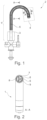
- FIG. 1 shows in a schematic view an exemplary embodiment of a water armature 2 proposed here.
- the water armature 2 has an outlet 1 proposed here.
- the outlet 1 has an inlet region 3 and an outlet region 4 .
- a tube 5 extends through the outlet body 6 of the outlet 1 from the inlet region 3 to the outlet region 4 .
- Three fluid channels 7 , 8 , 9 which run parallel to one another and separate from one another are formed in the tube 5 .
- FIG. 2 shows in a schematic view a sectional, detailed view of an embodiment according to FIG. 1 .
- the sectional view according to FIG. 2 is named Section A-A in FIG. 1 .
- the reference numerals are used uniformly, so that comprehensive reference can be made to previous statements, in particular in FIG. 1 .
- FIG. 3 shows in a schematic view a further sectional, detailed view of the embodiment according to FIG. 1 .
- the reference numerals are used uniformly, so that comprehensive reference can be made to previous statements, in particular in FIG. 1 .
- a connecting piece 11 is arranged in the outlet region 4 (not shown here, see FIG. 1 ).
- FIG. 4 shows in a schematic view a further sectional, detailed view of the embodiment according to FIG. 1 .
- the sectional view in FIG. 4 is named Section A-A in FIG. 1 and in FIG. 3 .
- the reference numerals are used uniformly, so that comprehensive reference can be made to previous statements, in particular in FIG. 1 .
- FIG. 5 a - e shows in a schematic view exemplary embodiment of a tube 5 , as it can be applied in the outlet proposed here, each in a front view.
- the reference numerals are used uniformly, so that comprehensive reference can be made to previous statements, in particular in FIG. 1 .
- FIG. 5 it can be seen that at least two of the fluid channels 6 , 7 , 8 can extend along a common separating wall 10 .
- FIG. 5 a - e show that by way of example and how at least two of the fluid channels 7 , 8 , 9 can be arranged so as to be distributed over a circumference of the tube 5 .
- FIGS. 5 d and 5 e show that by way of example and how at least two of the fluid channels 7 , 8 , 9 can be arranged radially one after another.
- FIG. 6 shows in a schematic view a perspective view of the tube 5 according to FIG. 5 b .
- the reference numerals are used uniformly, so that comprehensive reference can be made to previous statements.
- FIG. 7 shows in a schematic view a perspective view of the tube 5 according to FIG. 5 b .
- the reference numerals are used uniformly, so that comprehensive reference can be made to previous statements.
- the view in FIG. 7 shows that by way of example and how a transition piece 12 can be associated with each of the fluid channels.
- FIG. 8 shows in a schematic view a sectional, detailed view of an exemplary embodiment of an outlet 1 proposed here.
- the reference numerals are used uniformly, so that comprehensive reference can be made to previous statements. It can be seen that the outlet body 6 can also be built in several parts.
- FIG. 9 shows in a schematic view a sectional, detailed view of a further exemplary embodiment of an outlet proposed here 1 .
- the reference numerals are used uniformly, so that comprehensive reference can be made to previous statements.
- a connecting piece 11 is shown in shape of a cylinder.
- FIG. 9 shows that between the tube 5 and the connecting piece 11 at least two transition pieces 12 can be arranged adjacent to one another.
- FIG. 10 shows in a schematic view a further sectional, detailed view of the embodiment according to FIG. 9 .
- FIG. 11 shows in a schematic view a further sectional, detailed view of the embodiment according to FIG. 9 .
- the outlet body 6 is hidden.
- FIG. 12 shows in a schematic view a sectional, detailed view of a further exemplary embodiment of an outlet 1 proposed here.
- the reference numerals are used uniformly, so that comprehensive reference can be made to previous statements.
- a connecting piece 11 is shown in the shape of a plate.
- FIG. 13 shows a schematic view of a further sectional, detailed view of the embodiment according to FIG. 12 .
- FIG. 14 shows a schematic view of a further sectional, detailed view of the embodiment according to FIG. 12 .
- the outlet body 6 is hidden.
- FIG. 15 shows in a schematic view embodiment of a transition piece 12 , as it can be applied in the outlet proposed here.
- FIG. 15 shows three exemplary embodiments of the transition piece 12 . It can be seen that, in particular, the inner contours of the transition pieces 12 can be formed differently.
- FIG. 16 shows in a schematic view a further exemplary embodiment of a water armature 2 proposed here.
- the reference numerals are used uniformly, so that comprehensive reference can be made to previous statements.
- FIG. 16 shows by way of example that the tube 5 shown here and also referred to here in particular as a multi-lumen case can also be used in connection with a removable sprayer or with a pull-out variant.
- a jacket (not shown here), which can contribute to a mobility of the tube 5 in the outlet 1 of the water armature 2 .
- the jacket can be formed, for example, with a stainless-steel mesh or fiber optic threads.
- a weight 13 can be mounted at the lowest point of the looping. This can, for example, be a lead weight or a plastic component, optionally with a weight.
- FIG. 17 shows in a schematic view a further exemplary embodiment of a water armature proposed here 2 .
- the reference numerals are used uniformly, so that comprehensive reference can be made to previous statements.
- FIG. 17 also shows a possible application of the design introduced here with a removable sprayer or with a pull-out variant.
- the variant according to FIG. 17 is different from the one in FIG. 16 , in particular in that the weight 13 in FIG. 17 also forms a marking 14 , in order to assign the interior channels 7 , 8 , 9 of tube 5 , which cannot be seen here, to further components (for example, connecting pieces, threaded connections) possible.
- FIG. 18 shows a schematic view of a sequence of a method proposed here.
- the method aids in the production of an outlet for a water armature.
- the series of the method steps a), b) and c) shown with the blocks 110 , 120 and 130 usually results from a regular operational sequence.
- the steps a), b) and c), in particular the steps a) and b) can also be carried out at least partially in parallel or even simultaneously.
- an outlet body is provided in view 120 .
- a tube is provided in which at least three channels are formed that run parallel to one another and separate from one another.
- the tube is introduced into the outlet body.
Landscapes
- Engineering & Computer Science (AREA)
- General Engineering & Computer Science (AREA)
- Health & Medical Sciences (AREA)
- Life Sciences & Earth Sciences (AREA)
- Hydrology & Water Resources (AREA)
- Public Health (AREA)
- Water Supply & Treatment (AREA)
- Mechanical Engineering (AREA)
- Rigid Pipes And Flexible Pipes (AREA)
- Devices For Dispensing Beverages (AREA)
- Branch Pipes, Bends, And The Like (AREA)
Applications Claiming Priority (3)
| Application Number | Priority Date | Filing Date | Title |
|---|---|---|---|
| DE102018007226.7 | 2018-09-13 | ||
| DE102018007226.7A DE102018007226A1 (de) | 2018-09-13 | 2018-09-13 | Auslauf für eine Wasserarmatur |
| PCT/EP2019/074526 WO2020053408A1 (de) | 2018-09-13 | 2019-09-13 | Auslauf für eine wasserarmatur |
Publications (2)
| Publication Number | Publication Date |
|---|---|
| US20220049479A1 US20220049479A1 (en) | 2022-02-17 |
| US11926999B2 true US11926999B2 (en) | 2024-03-12 |
Family
ID=67988984
Family Applications (1)
| Application Number | Title | Priority Date | Filing Date |
|---|---|---|---|
| US17/275,329 Active 2040-11-09 US11926999B2 (en) | 2018-09-13 | 2019-09-13 | Outlet for a water armature |
Country Status (5)
| Country | Link |
|---|---|
| US (1) | US11926999B2 (zh) |
| EP (1) | EP3850164A1 (zh) |
| CN (1) | CN112513383A (zh) |
| DE (1) | DE102018007226A1 (zh) |
| WO (1) | WO2020053408A1 (zh) |
Families Citing this family (5)
| Publication number | Priority date | Publication date | Assignee | Title |
|---|---|---|---|---|
| DE102019219489A1 (de) * | 2019-12-12 | 2021-06-17 | Hansgrohe Se | Sanitäre Auszugsschlaucharmatur |
| DE102020105247A1 (de) | 2020-02-27 | 2021-09-02 | Kludi Gmbh & Co. Kg | Wasserauslaufarmatur mit ausziehbarer Geschirrbrause |
| JP2022120504A (ja) * | 2021-02-05 | 2022-08-18 | 日本サーモスタット株式会社 | 車両の冷却回路用配管、及びこれを用いた冷却回路 |
| DE102022106361A1 (de) | 2022-03-18 | 2023-09-21 | Grohe Ag | Sanitärarmatur mit einem Schlauch |
| DE102022106832A1 (de) | 2022-03-23 | 2023-09-28 | Grohe Ag | Sanitärarmatur mit einem Schlauch |
Citations (8)
| Publication number | Priority date | Publication date | Assignee | Title |
|---|---|---|---|---|
| DE10317753A1 (de) | 2002-12-10 | 2004-07-15 | Vera Wollner | Duschvorrichtung |
| WO2007113663A2 (en) | 2006-04-05 | 2007-10-11 | Electrolux Home Products Corporation N.V. | Sink tap assembly |
| WO2017123087A1 (en) | 2016-01-11 | 2017-07-20 | Henri Peteri Beheer B.V. | Mixing tap for dispensing water |
| DE102016000766A1 (de) | 2016-01-27 | 2017-07-27 | Neoperl Gmbh | Sanitäres Auslaufstück, Sanitärarmatur und Verwendung eines Auslaufstücks |
| DE102017101566B3 (de) | 2017-01-26 | 2018-06-28 | Neoperl Gmbh | Schlauchanschlussanordnung, Verwendung einer Schlauchanschlussanordnung und Sanitärarmatur |
| US20180209571A1 (en) * | 2017-01-26 | 2018-07-26 | Neoperl Gmbh | Hose connector assembly, use of a hose connector assembly, and sanitary fitting |
| US20190032309A1 (en) * | 2016-01-27 | 2019-01-31 | Neoperl Gmbh | Sanitary outlet piece, sanitary fitting and use of an outlet piece |
| US20210388582A1 (en) * | 2020-06-11 | 2021-12-16 | Delta Faucet Company | Manifold with insert for waterway assembly |
Family Cites Families (3)
| Publication number | Priority date | Publication date | Assignee | Title |
|---|---|---|---|---|
| US7070125B2 (en) * | 2003-05-16 | 2006-07-04 | Newfrey Llc | Multi-pattern pull-out spray head |
| DE102005061974B3 (de) * | 2005-12-23 | 2007-06-06 | Hansa Metallwerke Ag | Sanitäre Wasserauslaufarmatur |
| DE102013003926A1 (de) * | 2013-03-08 | 2014-09-25 | Neoperl Gmbh | Sanitäres Einbauteil, Innenschlauchanordnung für eine Sanitärarmatur und Sanitärarmatur |
-
2018
- 2018-09-13 DE DE102018007226.7A patent/DE102018007226A1/de active Pending
-
2019
- 2019-09-13 WO PCT/EP2019/074526 patent/WO2020053408A1/de unknown
- 2019-09-13 EP EP19769768.3A patent/EP3850164A1/de active Pending
- 2019-09-13 US US17/275,329 patent/US11926999B2/en active Active
- 2019-09-13 CN CN201980048701.3A patent/CN112513383A/zh active Pending
Patent Citations (8)
| Publication number | Priority date | Publication date | Assignee | Title |
|---|---|---|---|---|
| DE10317753A1 (de) | 2002-12-10 | 2004-07-15 | Vera Wollner | Duschvorrichtung |
| WO2007113663A2 (en) | 2006-04-05 | 2007-10-11 | Electrolux Home Products Corporation N.V. | Sink tap assembly |
| WO2017123087A1 (en) | 2016-01-11 | 2017-07-20 | Henri Peteri Beheer B.V. | Mixing tap for dispensing water |
| DE102016000766A1 (de) | 2016-01-27 | 2017-07-27 | Neoperl Gmbh | Sanitäres Auslaufstück, Sanitärarmatur und Verwendung eines Auslaufstücks |
| US20190032309A1 (en) * | 2016-01-27 | 2019-01-31 | Neoperl Gmbh | Sanitary outlet piece, sanitary fitting and use of an outlet piece |
| DE102017101566B3 (de) | 2017-01-26 | 2018-06-28 | Neoperl Gmbh | Schlauchanschlussanordnung, Verwendung einer Schlauchanschlussanordnung und Sanitärarmatur |
| US20180209571A1 (en) * | 2017-01-26 | 2018-07-26 | Neoperl Gmbh | Hose connector assembly, use of a hose connector assembly, and sanitary fitting |
| US20210388582A1 (en) * | 2020-06-11 | 2021-12-16 | Delta Faucet Company | Manifold with insert for waterway assembly |
Non-Patent Citations (1)
| Title |
|---|
| International Search Report dated Dec. 5, 2019, in International (PCT) Application No. PCT/EP2019/074526. |
Also Published As
| Publication number | Publication date |
|---|---|
| DE102018007226A1 (de) | 2020-03-19 |
| CN112513383A (zh) | 2021-03-16 |
| EP3850164A1 (de) | 2021-07-21 |
| US20220049479A1 (en) | 2022-02-17 |
| WO2020053408A1 (de) | 2020-03-19 |
Similar Documents
| Publication | Publication Date | Title |
|---|---|---|
| US11926999B2 (en) | Outlet for a water armature | |
| US9199252B2 (en) | Shower device | |
| US9668452B2 (en) | Device for production of dairy products, especially milk foam | |
| RU2531391C2 (ru) | Экструзионная оснастка для экструзии трубчатого изделия | |
| KR102060845B1 (ko) | 탭 그리고 상기 탭과 보일러 장치를 포함하는 어셈블리 | |
| RU2612712C1 (ru) | Распылительная насадка для текучей среды | |
| US8302620B2 (en) | Water inlet/outlet assembly for faucet | |
| CN106061617B (zh) | 具有多通道喷口出口单元的淋浴器 | |
| US8016215B1 (en) | Head for showering and the like | |
| CN104696551A (zh) | 水龙头金具制造方法 | |
| KR20170084110A (ko) | 다층 사출 성형 제품을 생산하기 위한 사출 몰딩 디바이스를 위한 공-사출 노즐 | |
| CN109073116B (zh) | 具有水流稳定性的水龙头接头 | |
| JP3220785U (ja) | 微細気泡発生装置 | |
| JPS5829209B2 (ja) | 環状ダイ | |
| AU2015270279A1 (en) | Fluid restriction nozzle for hand washing | |
| CN109263013A (zh) | 一种耐磨抗高温电子连接线挤塑机模具 | |
| KR100926946B1 (ko) | 각층의 두께 조절 유로제어 시스템이 구비된 다층관 압출 장치 및 다층관 | |
| CN209775491U (zh) | 一种涂塑水带成型机头结构 | |
| US9974709B2 (en) | Nozzles | |
| KR20180093641A (ko) | 합성수지관 압출장치 | |
| CN215892865U (zh) | 分流器 | |
| US10407883B2 (en) | Curved plastic faucet | |
| CN207449071U (zh) | 一种挤塑装置 | |
| JP2016118215A (ja) | 継手 | |
| KR20160076134A (ko) | 복합 코안다 노즐 |
Legal Events
| Date | Code | Title | Description |
|---|---|---|---|
| AS | Assignment |
Owner name: GROHE AG, GERMANY Free format text: ASSIGNMENT OF ASSIGNORS INTEREST;ASSIGNORS:MAINKA, DAVID;WOESTHOFF, WULF;SCHLUETER, MATTHIAS;SIGNING DATES FROM 20201216 TO 20210114;REEL/FRAME:055563/0465 |
|
| FEPP | Fee payment procedure |
Free format text: ENTITY STATUS SET TO UNDISCOUNTED (ORIGINAL EVENT CODE: BIG.); ENTITY STATUS OF PATENT OWNER: LARGE ENTITY |
|
| STPP | Information on status: patent application and granting procedure in general |
Free format text: DOCKETED NEW CASE - READY FOR EXAMINATION |
|
| STPP | Information on status: patent application and granting procedure in general |
Free format text: NON FINAL ACTION MAILED |
|
| STPP | Information on status: patent application and granting procedure in general |
Free format text: RESPONSE TO NON-FINAL OFFICE ACTION ENTERED AND FORWARDED TO EXAMINER |
|
| STPP | Information on status: patent application and granting procedure in general |
Free format text: NOTICE OF ALLOWANCE MAILED -- APPLICATION RECEIVED IN OFFICE OF PUBLICATIONS |
|
| STPP | Information on status: patent application and granting procedure in general |
Free format text: PUBLICATIONS -- ISSUE FEE PAYMENT VERIFIED |
|
| STCF | Information on status: patent grant |
Free format text: PATENTED CASE |