US11554492B2 - Workpiece conveying system, conveyed workpiece number detector, and control method for the workpiece conveying system - Google Patents
Workpiece conveying system, conveyed workpiece number detector, and control method for the workpiece conveying system Download PDFInfo
- Publication number
- US11554492B2 US11554492B2 US16/738,860 US202016738860A US11554492B2 US 11554492 B2 US11554492 B2 US 11554492B2 US 202016738860 A US202016738860 A US 202016738860A US 11554492 B2 US11554492 B2 US 11554492B2
- Authority
- US
- United States
- Prior art keywords
- workpiece
- holding unit
- workpieces
- held
- conveyed
- Prior art date
- Legal status (The legal status is an assumption and is not a legal conclusion. Google has not performed a legal analysis and makes no representation as to the accuracy of the status listed.)
- Active, expires
Links
Images


Classifications
-
- B—PERFORMING OPERATIONS; TRANSPORTING
- B25—HAND TOOLS; PORTABLE POWER-DRIVEN TOOLS; MANIPULATORS
- B25J—MANIPULATORS; CHAMBERS PROVIDED WITH MANIPULATION DEVICES
- B25J9/00—Programme-controlled manipulators
- B25J9/16—Programme controls
- B25J9/1694—Programme controls characterised by use of sensors other than normal servo-feedback from position, speed or acceleration sensors, perception control, multi-sensor controlled systems, sensor fusion
-
- B—PERFORMING OPERATIONS; TRANSPORTING
- B21—MECHANICAL METAL-WORKING WITHOUT ESSENTIALLY REMOVING MATERIAL; PUNCHING METAL
- B21D—WORKING OR PROCESSING OF SHEET METAL OR METAL TUBES, RODS OR PROFILES WITHOUT ESSENTIALLY REMOVING MATERIAL; PUNCHING METAL
- B21D43/00—Feeding, positioning or storing devices combined with, or arranged in, or specially adapted for use in connection with, apparatus for working or processing sheet metal, metal tubes or metal profiles; Associations therewith of cutting devices
- B21D43/20—Storage arrangements; Piling or unpiling
- B21D43/24—Devices for removing sheets from a stack
-
- B—PERFORMING OPERATIONS; TRANSPORTING
- B21—MECHANICAL METAL-WORKING WITHOUT ESSENTIALLY REMOVING MATERIAL; PUNCHING METAL
- B21D—WORKING OR PROCESSING OF SHEET METAL OR METAL TUBES, RODS OR PROFILES WITHOUT ESSENTIALLY REMOVING MATERIAL; PUNCHING METAL
- B21D43/00—Feeding, positioning or storing devices combined with, or arranged in, or specially adapted for use in connection with, apparatus for working or processing sheet metal, metal tubes or metal profiles; Associations therewith of cutting devices
- B21D43/02—Advancing work in relation to the stroke of the die or tool
- B21D43/021—Control or correction devices in association with moving strips
-
- B—PERFORMING OPERATIONS; TRANSPORTING
- B21—MECHANICAL METAL-WORKING WITHOUT ESSENTIALLY REMOVING MATERIAL; PUNCHING METAL
- B21D—WORKING OR PROCESSING OF SHEET METAL OR METAL TUBES, RODS OR PROFILES WITHOUT ESSENTIALLY REMOVING MATERIAL; PUNCHING METAL
- B21D43/00—Feeding, positioning or storing devices combined with, or arranged in, or specially adapted for use in connection with, apparatus for working or processing sheet metal, metal tubes or metal profiles; Associations therewith of cutting devices
- B21D43/26—Stops
-
- B—PERFORMING OPERATIONS; TRANSPORTING
- B25—HAND TOOLS; PORTABLE POWER-DRIVEN TOOLS; MANIPULATORS
- B25J—MANIPULATORS; CHAMBERS PROVIDED WITH MANIPULATION DEVICES
- B25J15/00—Gripping heads and other end effectors
- B25J15/008—Gripping heads and other end effectors with sticking, gluing or adhesive means
-
- B—PERFORMING OPERATIONS; TRANSPORTING
- B65—CONVEYING; PACKING; STORING; HANDLING THIN OR FILAMENTARY MATERIAL
- B65G—TRANSPORT OR STORAGE DEVICES, e.g. CONVEYORS FOR LOADING OR TIPPING, SHOP CONVEYOR SYSTEMS OR PNEUMATIC TUBE CONVEYORS
- B65G59/00—De-stacking of articles
- B65G59/02—De-stacking from the top of the stack
- B65G59/04—De-stacking from the top of the stack by suction or magnetic devices
Definitions
- the present invention relates to a technology of improving a workpiece conveying system configured to successively take a sheet-like member from a top of a stack (bunch) stacking a plurality of sheet-like workpieces one by one, and to convey the sheet-like member to, for example, a pressing machine in a next step (downstream step).
- the workpiece conveying system refers to a system configured to take a workpiece from a top of a bunch-like sheet group (bunch (stack) stacking a plurality of sheet-like workpieces) one by one, and convey (feed) the workpiece to a next step (for example, to the pressing machine).
- the upper and lower workpieces W closely attract (or adhere) to each other due to, for example, an oil attracting (or adhering) to surfaces of the workpieces W.
- an uppermost workpiece W is intended to be lifted and conveyed, in some cases, a workpiece W directly below the uppermost workpiece W is also lifted together.
- This is what is called a state in which two workpieces (or double workpieces) are taken.
- the workpieces W are set to, for example, the pressing machine in the next step under the state in which the two workpieces are taken, various troubles are caused. Accordingly, it has been required to detect taking of two workpieces before conveying the workpieces to the next step, to thereby prevent the workpieces from being conveyed to the next step under the state in which the two workpieces are taken.
- a workpiece conveying system 1 as illustrated in FIG. 9 and described in Japanese Patent Application Laid-open No. 2014-172047, when the uppermost workpiece W among workpieces W stacked in a bunch-like (stack-like) shape is lifted one by one by a workpiece holding unit 7 of a workpiece conveying device 9 formed of an articulated arm robot, before the workpiece W is conveyed to the next step (downstream step), a workpiece receiving member 13 is moved between the lifted workpiece W and the stack of the remaining workpieces W, and a two-workpiece (or double workpieces) taking detection unit 17 of the workpiece receiving member 13 detects whether or not two workpieces (or double workpieces) are taken.
- the workpiece W is conveyed subsequently by the workpiece conveying device 9 to the next step.
- the workpiece conveying system 1 described in Japanese Patent Application Laid-open No. 2014-172047 is configured so that, when the detection result is that two workpieces W are taken (the detection result is abnormal), the workpieces W (two taken workpieces W) held by the workpiece holding unit 7 are placed on a material table 19 after the workpiece receiving member 13 and the workpieces W (and the workpiece holding unit 7 ) are moved to a position above the material table 19 , and then the workpiece receiving member 13 is retreated from the position above the material table 19 .
- the two-workpiece taking detection unit 17 detects a thickness of the workpiece(s) W held by the workpiece holding unit 7 , and detects, based on the detection result, whether the number of workpieces W held by the workpiece holding unit 7 is one or two (see FIG. 10 ).
- the conveyed workpiece number detector detects that the number of workpieces held by the workpiece holding unit is one, the normal workpiece conveying operation is continued subsequently, and the workpiece is conveyed to a next step, and at the detection timing, when the conveyed workpiece number detector detects that the number of workpieces held by the workpiece holding unit is multiple, the multiple workpieces are discharged into a collection box without being conveyed to the next step.
- a workpiece conveying system configured to convey a sheet-like workpiece to a downstream step, including: a workpiece conveyor configured to hold and lift, by a workpiece holding unit, an uppermost workpiece of a stack stacking a plurality of workpieces through attraction holding, and convey the uppermost workpiece of the stack to the downstream step one by one; and a conveyed workpiece posture detector configured to detect a posture of workpieces held by the workpiece holding unit at a detection timing at which the workpiece held and raised by the workpiece holding unit in accordance with a normal workpiece conveying operation performed by the workpiece conveyor reaches an upper limit position of raising the workpiece, at which a moving speed component of the workpiece in a raising direction is 0.
- the conveyed workpiece posture detector detects that a posture of the workpiece held by the workpiece holding unit is normal, the normal workpiece conveying operation is continued subsequently, and the workpiece is conveyed to a next step, and at the detection timing, when the conveyed workpiece posture detector detects that the posture of the workpiece held by the workpiece holding unit is abnormal, the workpiece is conveyed to the next step while correcting the posture of the workpiece to a normal posture.
- a workpiece conveying system configured to convey a sheet-like workpiece to a downstream step, including: a workpiece conveyor configured to hold and lift, by a workpiece holding unit, an uppermost workpiece of a stack stacking a plurality of workpieces through attraction holding, and convey the uppermost workpiece of the stack to the downstream step one by one; a conveyed workpiece number detector configured to detect the number of workpieces held by the workpiece holding unit at a detection timing at which the workpiece held and raised by the workpiece holding unit in accordance with a normal workpiece conveying operation performed by the workpiece conveyor reaches an upper limit position of raising the workpiece, at which a moving speed component of the workpiece in a raising direction is 0; and a conveyed workpiece posture detector configured to detect a posture of the workpiece held by the workpiece holding unit at the detection timing at which the workpiece held and raised by the workpiece holding unit in accordance with the normal workpiece conveying operation performed by the work
- the detection timing when the conveyed workpiece number detector detects that the number of workpieces held by the workpiece holding unit is one and the conveyed workpiece posture detector detects that the posture of the workpiece held by the workpiece holding unit is normal, the normal workpiece conveying operation is continued subsequently, and the workpiece is conveyed to a next step, at the detection timing, when the conveyed workpiece number detector detects that the number of workpieces held by the workpiece holding unit is one and the conveyed workpiece posture detector detects that the posture of the workpiece held by the workpiece holding unit is abnormal, the workpiece is conveyed to the next step while correcting the posture of the workpiece to a normal posture, and at the detection timing, when the conveyed workpiece number detector detects that the number of workpieces held by the workpiece holding unit is multiple, the multiple workpieces are discharged into a collection box without being conveyed to the next step.
- the workpiece conveying system further includes a workpiece stopper configured to be brought into abutment against, at the upper limit position of raising the workpiece, an upper surface of the workpiece held and raised by the workpiece holding unit.
- a conveyed workpiece number detector provided in a workpiece conveying system configured to hold and lift, by a workpiece holding unit, an uppermost workpiece of a stack stacking a plurality of workpieces through attraction holding, and convey the uppermost workpiece of the stack to a downstream step one by one
- the conveyed workpiece number detector being configured to detect the number of workpieces held by the workpiece holding unit at a detection timing at which the workpiece held and raised by the workpiece holding unit in accordance with a normal workpiece conveying operation performed by the workpiece conveying system reaches an upper limit position of raising the workpiece, at which a moving speed component of the workpiece in a raising direction is 0.
- a control method for a workpiece conveying system configured to hold and lift, by a workpiece holding unit, an uppermost workpiece of a stack stacking a plurality of workpieces through attraction holding, and convey the uppermost workpiece of the stack to a downstream step one by one
- the control method including: detecting the number of workpieces held by the workpiece holding unit at a detection timing at which the workpiece held and raised by the workpiece holding unit in accordance with a normal workpiece conveying operation performed by the workpiece conveying system reaches an upper limit position of raising the workpiece, at which a moving speed component of the workpiece in a raising direction is 0; continuing, subsequently, the normal workpiece conveying operation to convey the workpiece to a next step when the detection result is that the number of workpieces held by the workpiece holding unit is one; and discharging a plurality of workpieces into a collection box without conveying the plurality of workpieces to the next step when the detection result is
- a control method for a workpiece conveying system configured to hold and lift, by a workpiece holding unit, an uppermost workpiece of a stack stacking a plurality of workpieces through attraction holding, and convey the uppermost workpiece of the stack to a downstream step one by one
- the control method including: detecting the number of workpieces and a posture of the workpiece held by the workpiece holding unit at a detection timing at which the workpiece held and raised by the workpiece holding unit in accordance with a normal workpiece conveying operation performed by the workpiece conveying system reaches an upper limit position of raising the workpiece, at which a moving speed component of the workpiece in a raising direction is 0; continuing, subsequently, the normal workpiece conveying operation to convey the workpiece to a next step when the detection result is that the number of workpieces held by the workpiece holding unit is one and the posture of the workpiece held by the workpiece holding unit is normal; conveying the workpiece to the next step while correcting
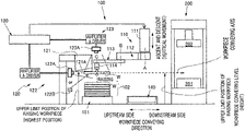
- FIG. 1 is a configuration view for schematically illustrating an entire configuration of a workpiece conveying system according to one embodiment of the present invention (view seen from a horizontal direction orthogonal to a workpiece conveying direction).
- FIG. 2 is a view for illustrating a workpiece conveying operation performed by the workpiece conveying system according to the embodiment (normal example in which a single workpiece is taken).
- FIG. 3 is a view for illustrating the workpiece conveying operation performed by the workpiece conveying system according to the embodiment (abnormal example in which two workpieces are taken).
- FIG. 4 is a flowchart for showing an example of control of workpiece conveyance performed by the workpiece conveying system according to the embodiment (case of detecting taking of two workpieces).
- FIG. 5 is a view for illustrating the workpiece conveying operation performed by the workpiece conveying system according to the embodiment (example of a case of detecting a posture of the workpiece).
- FIG. 6 is a plan view for illustrating correction of the posture of the workpiece in the workpiece conveying system according to the embodiment.
- FIG. 7 is a flowchart for showing an example of control of workpiece conveyance performed by the workpiece conveying system according to the embodiment (case of detecting the posture of the workpiece).
- FIG. 8 is a flowchart for showing an example of control of workpiece conveyance performed by the workpiece conveying system according to the embodiment (case of detecting taking of two workpieces and detecting the posture of the workpiece).
- FIG. 9 is a perspective view for illustrating an example of a configuration of a related-art destack feeder.
- FIG. 10 is a side view for illustrating the example of the configuration of the related-art destack feeder.
- the present invention has been made in view of the above-mentioned circumstances, and has an object to provide a workpiece conveying system, which has a simple and low-cost configuration, and is capable of detecting taking of two (or double) workpieces and detecting a posture of a workpiece efficiently and accurately, thereby being capable of meeting a demand for high-speed conveyance of the workpiece. Further, the present invention has another object to provide a conveyed workpiece number detector to be used in the workpiece conveying system, and a control method for the workpiece conveying system.
- FIG. 1 is a configuration view for schematically illustrating an entire configuration of the workpiece conveying system 100 (view seen from a horizontal direction substantially orthogonal to a workpiece conveying direction).
- the workpiece conveying system 100 is arranged in an upstream side (front-end step) of processing steps of a pressing machine 200 , and is configured to take an uppermost workpiece W from a stack (bunch stacking a plurality of sheet-like (thin-plate-like) workpieces W) 102 placed on a stacker 101 so as to convey (feed) the workpieces W one by one to the pressing machine 200 in a next step (downstream step).
- the uppermost workpiece W of the stack 102 is taken by a workpiece conveyor 110 .
- the workpiece conveyor 110 includes:
- a vertically movable frame 111 configured to be movable in a vertical direction
- first arm 112 having a proximal end portion supported on the vertically movable frame 111 so as to be freely swingable in a substantially horizontal plane via a first joint A;
- a second arm 113 having a proximal end portion supported on a distal end portion of the first arm 112 so as to be freely swingable in the substantially horizontal plane via a second joint B;
- a workpiece holding unit 114 supported on a distal end of the second arm 113 so as to be freely rotatable in the substantially horizontal plane via a third joint C, and configured to hold and release the workpiece W.
- the workpiece holding unit 114 includes a plurality of workpiece holding portions.
- the workpiece conveyor 110 is controlled so as to convey the workpiece W in the following steps.
- the first arm 112 and the second arm 113 are swung in the substantially horizontal plane about the first joint A and the second joint B, respectively, thereby moving the workpiece holding unit 114 to a position above the uppermost workpiece W of the stack 102 .
- the vertically movable frame 111 is lowered, thereby bringing the workpiece holding unit 114 into contact with an upper surface of the uppermost workpiece W of the stack 102 .
- the workpiece holding unit 114 holds the uppermost workpiece W of the stack 102 by a method such as vacuum suction (or magnetic attraction), and then the vertically movable frame 111 is raised. In this manner, the workpiece W held by the workpiece holding unit 114 is separated from the stack 102 and lifted upward.
- a method such as vacuum suction (or magnetic attraction)
- the first arm 112 and the second arm 113 are swung in the substantially horizontal plane about the first joint A and the second joint B, respectively, thereby moving the workpiece holding unit 114 and the workpiece W to a position above a lower die 201 of the pressing machine 200 .
- an upper die 202 configured to be vertically movable performs press forming on the workpiece W set on the lower die 201 .
- the workpiece conveyor 110 is controlled so as to lift and take one uppermost workpiece W of the stack 102 at a time, and then convey (feed) the workpiece W to the pressing machine 200 in the next step one by one.
- the workpiece conveying system 100 includes a conveyed workpiece state detector 120 .
- the conveyed workpiece state detector 120 can detect so-called taking of two workpieces (or double workpieces) efficiently with high accuracy. The taking of two workpieces occurs when the workpiece conveyor 110 is intended to take the uppermost workpiece W from the stack 102 .
- the conveyed workpiece state detector 120 includes a workpiece stopper 121 .
- the workpiece stopper 121 At an upper limit position of raising the workpiece W (height position of finishing a workpiece raising operation), the workpiece stopper 121 is configured to come into abutment against (contact with) the upper surface of the workpiece W, which is raised while being held and lifted by the workpiece holding unit 114 , at a workpiece contact portion 121 A.
- the workpiece contact portion 121 A of the workpiece stopper 121 has such a planar positional relationship as to be sandwiched by at least two of the workpiece holding portions of the workpiece holding unit 114 when seen, for example, from an upper side of the workpiece W.
- the conveyed workpiece state detector 120 includes a two-workpiece (or double-workpieces) taking detector 122 .
- the two-workpiece taking detector 122 is configured to detect (a thickness of) the workpiece W at a position at which a lower end (workpiece contact portion 121 A) of the workpiece stopper 121 and the upper surface of the workpiece Ware brought into abutment against (contact with) each other.
- the two-workpiece taking detector 122 may be configured to detect the thickness of the workpiece W or taking of two workpieces through image analysis performed by a conveyance controller (control device) 130 based on data photographed by, for example, a camera 122 A, or may be configured to detect the thickness of the workpiece W by the conveyance controller 130 based on data obtained through laser irradiation from a laser 122 B.
- the two-workpiece taking detector 122 corresponds to a conveyed workpiece number detector according to the present invention.
- the conveyed workpiece state detector 120 includes a conveyed workpiece posture detector 123 .
- the conveyed workpiece posture detector 123 is configured to detect a posture of the workpiece W through image analysis performed by the conveyance controller 130 based on data photographed by, for example, a camera 123 A.
- the conveyed workpiece state detector 120 configured as described above detects the number of workpieces (taking of two workpieces) and/or the posture of the workpiece (for example, posture in a horizontal plane) through effective use of a timing at which the workpiece W raised while being held and lifted by the workpiece holding unit 114 in accordance with a normal workpiece conveying operation (control) reaches a position (highest position, upper limit position of raising the workpiece, or height position during conveyance of the workpiece in the horizontal direction) at which a moving speed component of the workpiece W in a raising direction is 0 (zero), for example, a timing at which the workpiece is switched so that, among workpiece conveying speed components, the moving speed component in the raising direction is zero and the workpiece has only a moving speed component in the horizontal direction.
- the above-mentioned timing corresponds to a detection timing according to the present invention.
- the conveyed workpiece state detector 120 can detect, for example, the thickness of the workpiece, taking of two workpieces, and the posture quickly with high accuracy without providing a step involving reduction in workpiece conveying speed, such as a step of stopping conveyance of the workpiece in order to detect taking of two workpieces.
- the workpiece stopper 121 suppresses the vibration through abutment against the workpiece W, to thereby achieve operations and effects of increasing detection accuracy in detection of taking of two workpieces and detection of the posture of the workpiece, which are performed by the conveyed workpiece state detector 120 . Therefore, when, for example, a workpiece involving no vibration is conveyed, the workpiece stopper 121 can be omitted. Further, when the workpiece W is made of a magnetic material, the workpiece stopper 121 includes a magnet as the workpiece contact portion 121 A. When the workpiece W is made of a nonmagnetic material, the workpiece stopper 121 has a vacuum suction structure as the workpiece contact portion 121 A.
- vibration generated when an operation of raising the workpiece W is stopped can be more reliably suppressed, thereby being capable of carrying out detection of the number of workpieces and detection of the posture of the workpiece quickly with high accuracy.
- control method of detecting the number of workpieces and conveying the workpiece, which is performed by the workpiece conveying system 100 including the conveyed workpiece state detector 120 (two-workpiece taking detector 122 ) according to this embodiment configured as described above.
- FIG. 4 is a flowchart for showing a case of detecting the number of workpieces (taking of two workpieces). Further, FIG. 2 and FIG. 3 are each a side view for illustrating an operation example of the workpiece conveying system 100 performed based on the flowchart of FIG. 4 . The control is carried out by the conveyance controller 130 .
- Step (represented as “S” in the drawings (the same holds true for the following description.)) 1 in accordance with the normal workpiece conveying operation (control), the workpiece conveyor 110 (conveyor) holds the uppermost workpiece W of the stack 102 and moves (ascends) to the upper limit position of raising the workpiece (hereinafter, also referred to as ascent limit).
- Step 2 at the timing at which the upper surface of the workpiece W is brought into abutment against (contact with) the workpiece contact portion 121 A of the workpiece stopper 121 , the two-workpiece taking detector 122 detects taking of two workpieces (double workpieces). Specifically, based on the data obtained from the camera 122 A or the laser 122 B, the two-workpiece taking detector 122 detects whether or not a single workpiece W is raised while being held and lifted by the workpiece holding unit 114 of the workpiece conveyor 110 .
- Step 3 When the detection result is Yes (taking of one workpiece (single workpiece): normal), the operation proceeds to Step 3 .
- the detection result is No (taking of two workpieces: abnormal), the operation proceeds to Step 5 .
- Step 3 the workpiece conveying system 100 operates as illustrated in FIG. 2 .
- Step 5 the workpiece conveying system 100 operates as illustrated in FIG. 3 .
- Step 3 a single workpiece W is held by the workpiece holding unit 114 , which is a normal state. Accordingly, the normal workpiece conveying operation (control) is continued subsequently, and the workpiece W is conveyed to the pressing machine 200 in the next step to convey (load or feed) the workpiece W to the lower die 201 (die).
- Step 4 the workpiece holding unit 114 of the workpiece conveyor 110 is moved from the pressing machine 200 to the stack 102 (stacker 101 ), and the operation returns to Step 1 in order to convey the subsequent workpiece W.
- Step 5 two (or more) workpieces W are held by the workpiece holding unit 114 , which is an abnormal state (what is called a state in which two workpieces are taken). Accordingly, the normal workpiece conveyance is not performed (is stopped), and the plurality of workpieces W held by the workpiece holding unit 114 are conveyed to a collection box 140 to release (discharge) the plurality of workpieces W into the collection box 140 . Then, the operation proceeds to Step 6 .
- Step 6 the workpiece holding unit 114 of the workpiece conveyor 110 is moved from the collection box 140 to the stack 102 (stacker 101 ), and the operation returns to Step 1 in order to convey the subsequent workpiece W.
- the workpiece conveying system 100 includes the conveyed workpiece state detector 120 , and the two-workpiece taking detector 122 detects taking of two workpieces at the timing at which an ascending speed component of the workpiece W is 0 (zero) while the workpiece conveyor 110 conveys the workpiece W in accordance with the normal workpiece conveying operation (control), specifically, the “timing at which the workpiece conveyor 110 holds the uppermost workpiece W of the stack 102 and moves (ascends) to the ascent limit, and the upper surface of the workpiece W is brought into abutment against (contact with) the workpiece contact portion 121 A of the workpiece stopper 121 ”.
- a workpiece conveying system which has a simple and low-cost configuration, and is capable of detecting taking of two workpieces efficiently and accurately, thereby being capable of meeting a demand for high-speed conveyance of the workpiece can be provided. Further, a conveyed workpiece number detector that is suitable for the workpiece conveying system, and a control method for the workpiece conveying system can be provided.
- the conveyed workpiece state detector 120 (two-workpiece taking detector 122 ) detects the number of workpieces (taking of two workpieces) through effective use of the timing at which the workpiece W raised while being held and lifted by the workpiece holding unit 114 in accordance with the normal workpiece conveying operation (control) reaches the position (highest position or upper limit position of raising the workpiece) at which the moving speed component of the workpiece in the raising direction is 0, for example, the timing at which the workpiece is switched so that, among the workpiece conveying speed components, the moving speed component in the raising direction is 0 and the workpiece has only the moving speed component in the horizontal direction.
- the present invention does not involve switching (special change) of acceleration of workpiece conveyance, which caused, for example, when reduced conveying speed is increased to detect taking of two workpieces.
- switching special change
- an unnecessary inertial force which is not required originally for conveyance, is not applied to the workpiece W supported by the workpiece holding unit 114 .
- the present invention can contribute to achievement of high-speed conveyance of the workpiece while maintaining a simplified configuration, reduction in weight, and cost reduction of each of the workpiece holding unit 114 and the workpiece conveyor 110 .
- the conveyed workpiece state detector 120 (two-workpiece taking detector 122 ) detects the number of workpieces (taking of two workpieces) through effective use of the timing at which the workpiece W raised while being held and lifted by the workpiece holding unit 114 in accordance with the normal workpiece conveying operation (control) reaches the position (highest position or upper limit position of raising the workpiece) at which the moving speed component of the workpiece in the raising direction is 0, for example, the timing at which the workpiece is switched so that, among the workpiece conveying speed components, the moving speed component in the raising direction is 0 and the workpiece has only the moving speed component in the horizontal direction.
- the number of workpieces (taking of two workpieces) can be detected with high accuracy while suppressing increase in time period for workpiece conveyance, which is required to lift the uppermost workpiece W of the stack 102 and then convey the workpiece W into the next step. Accordingly, the present invention can contribute to achievement of high-speed conveyance of the workpiece.
- the conveyed workpiece state detector 120 (two-workpiece taking detector 122 ) according to this embodiment is configured to bring the workpiece W, which is being conveyed, into abutment against (contact with) the lower end (workpiece contact portion 121 A) of the workpiece stopper 121 at the timing (timing of finishing the workpiece raising operation) of reaching the position (highest position or upper limit position of raising the workpiece) at which the moving speed component of the workpiece in the raising direction is 0, and is configured to bring the workpiece W into abutment against the lower end of the workpiece stopper 121 with use of movement of the workpiece along with conveyance of the workpiece W.
- it is not required to adopt such a complex configuration as to move the workpiece stopper 121 itself. Accordingly, the configuration is simplified, thereby being capable of suppressing increase in cost.
- control method of detecting the posture of workpiece and conveying the workpiece, which is performed by the workpiece conveying system 100 including the conveyed workpiece state detector 120 (conveyed workpiece posture detector 123 ) according to this embodiment.
- the control is carried out by the conveyance controller 130 .
- FIG. 5 and FIG. 6 are each a view for illustrating an operation example of the workpiece conveying system 100 performed based on the flowchart of FIG. 7 .
- Step 11 in accordance with the normal workpiece conveying operation control, the workpiece conveyor 110 (conveyor) holds the uppermost workpiece W of the stack 102 and moves (ascends) to the ascent limit.
- the conveyed workpiece posture detector 123 detects the posture of the workpiece W during conveyance. Specifically, through image analysis based on data photographed by, for example, the camera 123 A, the conveyed workpiece posture detector 123 detects the posture of the workpiece W with respect to an axis X of the workpiece conveying direction in the horizontal plane (see FIG. 7 ), and detects whether or not the workpiece W held by the workpiece holding unit 114 is held at a regular position.
- Step 13 When the detection result is Yes (the posture is normal), the operation proceeds to Step 13 .
- the detection result is No (the posture is abnormal), the operation proceeds to Step 15 .
- Step 13 the posture of the workpiece W held by the workpiece holding unit 114 is normal state. Accordingly, the normal workpiece conveying operation (control) is continued subsequently, and the workpiece W is conveyed to the pressing machine 200 in the next step to convey (load or feed) the workpiece W to the lower die 201 (die).
- Step 14 the workpiece holding unit 114 of the workpiece conveyor 110 is moved from the pressing machine 200 to the stack 102 (stacker 101 ), and the operation returns to Step 1 in order to convey the subsequent workpiece W.
- Step 15 the posture of the workpiece W held by the workpiece holding unit 114 is abnormal (see FIG. 7 ). Accordingly, while correcting (adjusting) the posture of the workpiece to a normal state by changing a relative position of the workpiece holding unit 114 to the second arm 113 (relative rotation angle position about the third joint C) so as to set the posture of the workpiece W held by the workpiece holding unit 114 to a predetermined posture (set a deviation amount (inclination angle) Y from the regular position to 0) (see FIG. 6 ), the workpiece W is conveyed to the pressing machine 200 in the next step to convey (load or feed) the workpiece W to the lower die 201 (die). After that, the operation proceeds to Step 14 , and then returns to Step 1 in order to convey the subsequent workpiece W.
- the workpiece conveying system 100 includes the conveyed workpiece state detector 120 , and the conveyed workpiece posture detector 123 detects the posture of the workpiece at the timing at which the ascending speed component of the workpiece W is 0 (zero) while the workpiece conveyor 110 conveys the workpiece W in accordance with the normal workpiece conveying operation (control), specifically, the “timing at which the workpiece conveyor 110 holds the uppermost workpiece W of the stack 102 and moves (ascends) to the ascent limit, and the upper surface of the workpiece W is brought into abutment against (contact with) the workpiece contact portion 121 A of the workpiece stopper 121 ”.
- a workpiece conveying system which has a simple and low-cost configuration, and is capable of detecting a posture of a workpiece efficiently and accurately, thereby being capable of meeting a demand for high-speed conveyance of the workpiece can be provided.
- the posture of the workpiece can be detected with high accuracy.
- the conveyed workpiece state detector 120 detects the posture of the workpiece through effective use of the timing at which the workpiece W raised while being held and lifted by the workpiece holding unit 114 in accordance with the normal workpiece conveying operation (control) reaches the position (highest position or upper limit position of raising the workpiece) at which the moving speed component of the workpiece in the raising direction is 0, for example, the timing at which the workpiece is switched so that, among the workpiece conveying speed components, the moving speed component in the raising direction is 0 and the workpiece has only the moving speed component in the horizontal direction.
- the present invention does not involve switching (special change) of acceleration of workpiece conveyance, which caused, for example, when reduced conveying speed is increased to detect the posture of the workpiece.
- an unnecessary inertial force which is not required originally for conveyance, is not applied to the workpiece W supported by the workpiece holding unit 114 .
- the present invention can contribute to achievement of high-speed conveyance of the workpiece while achieving a simplified configuration, reduction in weight, and cost reduction of each of the workpiece holding unit 114 and the workpiece conveyor 110 .
- the conveyed workpiece state detector 120 detects the posture of the workpiece through effective use of the timing at which the workpiece W raised while being held and lifted by the workpiece holding unit 114 in accordance with the normal workpiece conveying operation (control) reaches the position (highest position or upper limit position of raising the workpiece) at which the moving speed component of the workpiece in the raising direction is 0, for example, the timing at which the workpiece is switched so that, among the workpiece conveying speed components, the moving speed component in the raising direction is 0 and the workpiece has only the moving speed component in the horizontal direction.
- the posture of the workpiece can be detected with high accuracy while suppressing increase in time period for workpiece conveyance, which is required to lift the uppermost workpiece W of the stack 102 and then convey the workpiece W into the next step. Accordingly, the present invention can contribute to achievement of high-speed conveyance of the workpiece.
- the conveyed workpiece state detector 120 (conveyed workpiece posture detector 123 ) according to this embodiment is configured to bring the workpiece W, which is being conveyed, into abutment against (contact with) the lower end (workpiece contact portion 121 A) of the workpiece stopper 121 at the timing (timing of finishing the workpiece raising operation) of reaching the position (highest position or upper limit position of raising the workpiece) at which the moving speed component of the workpiece in the raising direction is 0, and is configured to bring the workpiece W into abutment against the lower end of the workpiece stopper 121 with use of movement of the workpiece along with conveyance of the workpiece W.
- it is not required to adopt such a complex configuration as to move the workpiece stopper 121 itself. Accordingly, the configuration is simplified, thereby being capable of suppressing increase in cost.
- the two-workpiece taking detector 122 and the conveyed workpiece posture detector 123 are described separately, but the conveyed workpiece state detector 120 may include both of the two-workpiece taking detector 122 and the conveyed workpiece posture detector 123 .
- Step 21 similarly to S 1 of FIG. 4 , in accordance with the normal workpiece conveying operation (control), the workpiece conveyor 110 (conveyor) holds the uppermost workpiece W of the stack 102 and moves (ascends) to the upper limit position of raising the workpiece.
- Step 22 similarly to S 2 of FIG. 4 , at the timing at which the upper surface of the workpiece W is brought into abutment against (contact with) the workpiece contact portion 121 A of the workpiece stopper 121 , the two-workpiece taking detector 122 detects taking of two workpieces (double workpieces).
- Step 23 When the detection result is Yes (taking of one workpiece: normal), the operation proceeds to Step 23 .
- Step 26 When the detection result is No (taking of two workpieces: abnormal), the operation proceeds to Step 26 .
- Step 23 at the same timing as that in Step 22 above, similarly to S 12 of FIG. 7 , the conveyed workpiece posture detector 123 detects the posture of the workpiece W during conveyance.
- Step 24 When the detection result is Yes (the posture is normal), the operation proceeds to Step 24 .
- the detection result is No (the posture is abnormal), the operation proceeds to Step 28 .
- Step 24 a single workpiece W is held by the workpiece holding unit 114 , which is a normal state, and the posture of the workpiece is normal. Accordingly, the normal workpiece conveying operation (control) is continued subsequently, and the workpiece W is conveyed to the pressing machine 200 in the next step to convey (load or feed) the workpiece W to the lower die 201 (die).
- Step 25 the workpiece holding unit 114 of the workpiece conveyor 110 is moved from the pressing machine 200 to the stack 102 (stacker 101 ), and the operation returns to Step 1 in order to convey the subsequent workpiece W.
- Step 26 to which the operation proceeds when the determination result is No in Step 22 (it is determined that two workpieces are taken), similarly to S 5 of FIG. 4 , two (or more) workpieces W are held by the workpiece holding unit 114 , which is an abnormal state (what is called a state in which two workpieces are taken). Accordingly, the normal workpiece conveyance is not performed (is stopped), and the plurality of workpieces W held by the workpiece holding unit 114 are conveyed to the collection box 140 to release (discharge) the plurality of workpieces W into the collection box 140 . Then, the operation proceeds to Step 27 .
- Step 27 similarly to S 6 of FIG. 4 , the workpiece holding unit 114 of the workpiece conveyor 110 is moved from the collection box 140 to the stack 102 (stacker 101 ), and the operation returns to Step 1 in order to convey the subsequent workpiece W.
- Step 28 to which the operation proceeds when the determination result is No in Step 23 (it is determined that the posture is abnormal) similarly to S 15 of FIG. 7 , the posture of the workpiece W held by the workpiece holding unit 114 is abnormal. Accordingly, while correcting (adjusting) the posture of the workpiece to a normal state by changing a relative position of the workpiece holding unit 114 to the second arm 113 (relative rotation angle position about the third joint C) so as to set the posture of the workpiece W held by the workpiece holding unit 114 to a predetermined posture (set the deviation (inclination angle) Y from the regular position to 0) (see FIG.
- the workpiece W is conveyed to the pressing machine 200 in the next step to convey (load or feed) the workpiece W to the lower die 201 .
- the operation proceeds to Step 25 , and then returns to Step 21 in order to convey the subsequent workpiece W.
- the flowchart of FIG. 8 does not show a flow of “performing detection (determination) of the posture of the workpiece after performing detection (determination) of taking of two workpieces”.
- the flowchart of FIG. 8 shows that “when one workpiece is taken (two workpieces are not taken), a conveying mode differs depending on whether or not the posture of the workpiece is held at a regular position (predetermined position having a desired width)”.
- the workpiece conveying system 100 includes the conveyed workpiece state detector 120 , and the two-workpiece taking detector 122 detects taking of two workpieces and conveyed workpiece posture detector 123 detects the posture of the workpiece at the timing at which the ascending speed component of the workpiece W is 0 (zero) while the workpiece conveyor 110 conveys the workpiece W in accordance with the normal workpiece conveying operation (control), specifically, the “timing at which the workpiece conveyor 110 holds the uppermost workpiece W of the stack 102 and moves (ascends) to the ascent limit, and the upper surface of the workpiece W is brought into abutment against (contact with) the workpiece contact portion 121 A of the workpiece stopper 121 ”.
- a workpiece conveying system which has a simple and low-cost configuration, and is capable of detecting taking of two workpieces and detecting a posture of a workpiece efficiently and accurately, thereby being capable of meeting a demand for high-speed conveyance of the workpiece can be provided.
- the conveyed workpiece state detector 120 (two-workpiece taking detector 122 and conveyed workpiece posture detector 123 ) detects taking of two workpieces and the posture of the workpiece through effective use of the timing at which the workpiece W raised while being held and lifted by the workpiece holding unit 114 in accordance with the normal workpiece conveying operation (control) reaches the position (highest position or upper limit position of raising the workpiece) at which the moving speed component of the workpiece in the raising direction is 0, for example, the timing at which the workpiece is switched so that, among the workpiece conveying speed components, the moving speed component in the raising direction is 0 and the workpiece has only the moving speed component in the horizontal direction.
- the present invention does not involve switching (special change) of acceleration of workpiece conveyance, which caused, for example, when reduced conveying speed is increased to detect the posture of the workpiece.
- an unnecessary inertial force which is not required originally for conveyance, is not applied to the workpiece W supported by the workpiece holding unit 114 .
- the present invention can contribute to achievement of high-speed conveyance of the workpiece while achieving a simplified configuration, reduction in weight, and cost reduction of each of the workpiece holding unit 114 and the workpiece conveyor 110 .
- the conveyed workpiece state detector 120 (two-workpiece taking detector 122 and conveyed workpiece posture detector 123 ) detects taking of two workpieces and the posture of the workpiece through effective use of the timing at which the workpiece W raised while being held and lifted by the workpiece holding unit 114 in accordance with the normal workpiece conveying operation (control) reaches the position (highest position or upper limit position of raising the workpiece) at which the moving speed component of the workpiece in the raising direction is 0, for example, the timing at which the workpiece is switched so that, among the workpiece conveying speed components, the moving speed component in the raising direction is 0 and the workpiece has only the moving speed component in the horizontal direction.
- the posture of the workpiece can be detected with high accuracy while suppressing increase in time period for workpiece conveyance, which is required to lift the uppermost workpiece W of the stack 102 and then convey the workpiece W into the next step. Accordingly, the present invention can contribute to achievement of high-speed conveyance of the workpiece.
- the conveyed workpiece state detector 120 (two-workpiece taking detector 122 and conveyed workpiece posture detector 123 ) according to this embodiment is configured to bring the workpiece W, which is being conveyed, into abutment against (contact with) the lower end (workpiece contact portion 121 A) of the workpiece stopper 121 at the timing (timing of finishing the workpiece raising operation) of reaching the position (highest position or upper limit position of raising the workpiece) at which the moving speed component of the workpiece in the raising direction is 0, and is configured to bring the workpiece W into abutment against the lower end of the workpiece stopper 121 with use of movement of the workpiece along with conveyance of the workpiece W.
- it is not required to adopt such a complex configuration as to move the workpiece stopper 121 itself. Accordingly, the configuration is simplified, thereby being capable of suppressing increase in cost.
- the workpiece conveying system according to the present invention is not limited to feeding of the workpiece to the pressing machine.
- the next step is not particularly limited.
- a material for the workpiece is not limited to metal. Other materials such as paper, glass, a resin, and wood are also applicable as the material for the workpiece.
- the workpiece conveying system 100 adopts the workpiece conveyor 110 including: the vertically movable frame 111 configured to be movable in the vertical direction; the first arm 112 configured to be freely swingable in the horizontal plane; the second arm 113 configured to be freely swingable in the horizontal plane; and the workpiece holding unit 114 configured to be freely rotatable in the horizontal plane, but the present invention is not limited thereto.
- a workpiece conveyor using an articulated robot as disclosed in Japanese Patent Application Laid-open No. 2014-172047, or another workpiece conveyor may be adopted.
- the conveyed workpiece state detector 120 can detect, for example, the thickness of the workpiece and taking of two workpieces with high accuracy through detection at the timing (detection timing) at which the moving speed component of the workpiece W during conveyance in the raising direction is 0 (zero).
- this timing (detection timing) is not limited to the timing (detection timing) at which the moving speed component in the raising direction when the workpiece W is lifted vertically is 0 (zero).
- the present invention is also applicable to a timing (detection timing) at which the moving speed component in the raising direction is 0 (zero) in a case in which the workpiece W is raised while being moved in the horizontal direction (that is, a case in which the moving speed component in the horizontal direction and the moving speed component in the raising direction are composited).
- a workpiece conveying system which has a simple and low-cost configuration, and is capable of detecting taking of two workpieces and detecting a posture of a workpiece efficiently and accurately, thereby being capable of meeting a demand for high-speed conveyance of the workpiece can be provided. Further, the present invention can provide a conveyed workpiece number detector that is suitable for the workpiece conveying system, and a control method for the workpiece conveying system.
Landscapes
- Engineering & Computer Science (AREA)
- Mechanical Engineering (AREA)
- Robotics (AREA)
- Specific Conveyance Elements (AREA)
- De-Stacking Of Articles (AREA)
- Manipulator (AREA)
Applications Claiming Priority (3)
| Application Number | Priority Date | Filing Date | Title |
|---|---|---|---|
| JPJP2019-010167 | 2019-01-24 | ||
| JP2019-10167 | 2019-01-24 | ||
| JP2019010167A JP7022084B2 (ja) | 2019-01-24 | 2019-01-24 | ワーク搬送システム、搬送ワーク枚数検出装置及びワーク搬送システムの制御方法 |
Publications (2)
| Publication Number | Publication Date |
|---|---|
| US20200238528A1 US20200238528A1 (en) | 2020-07-30 |
| US11554492B2 true US11554492B2 (en) | 2023-01-17 |
Family
ID=69185409
Family Applications (1)
| Application Number | Title | Priority Date | Filing Date |
|---|---|---|---|
| US16/738,860 Active 2041-05-21 US11554492B2 (en) | 2019-01-24 | 2020-01-09 | Workpiece conveying system, conveyed workpiece number detector, and control method for the workpiece conveying system |
Country Status (4)
| Country | Link |
|---|---|
| US (1) | US11554492B2 (de) |
| EP (1) | EP3685934B1 (de) |
| JP (1) | JP7022084B2 (de) |
| CN (1) | CN111468629A (de) |
Families Citing this family (2)
| Publication number | Priority date | Publication date | Assignee | Title |
|---|---|---|---|---|
| US11413658B2 (en) * | 2020-04-09 | 2022-08-16 | Raute Oyj | System and a method for sorting veneer sheets |
| CN112828934B (zh) * | 2021-01-04 | 2022-05-20 | 中联重科股份有限公司 | 确定臂架姿态的方法和装置、监控方法和装置及工程机械 |
Citations (19)
| Publication number | Priority date | Publication date | Assignee | Title |
|---|---|---|---|---|
| US4352627A (en) * | 1978-01-05 | 1982-10-05 | L. Schuler Gmbh | Loading device for a press |
| JPS62173335U (de) | 1986-04-24 | 1987-11-04 | ||
| US4804173A (en) | 1985-06-03 | 1989-02-14 | Roberts Corporation | Method and apparatus for moving individual sheets from a stack of sheets |
| US4905982A (en) * | 1986-03-11 | 1990-03-06 | Kabushiki Kaisha Komatsu Seisakusho | Double-blank detecting apparatus for use in destacker |
| US4971515A (en) * | 1985-06-03 | 1990-11-20 | Roberts Corporation | Apparatus for moving individual sheets from a stack of sheets |
| JPH08192236A (ja) | 1995-01-13 | 1996-07-30 | Amada Washino Co Ltd | 加工機におけるワーク搬送方法およびワーク搬送装置 |
| US5848785A (en) * | 1995-08-10 | 1998-12-15 | Lomir Engineering Limited | Sheet material feeding and unloading apparatus |
| US5899341A (en) * | 1997-02-26 | 1999-05-04 | Matsushita Electric Industrial Co., Ltd. | Method of and apparatus for transporting lead frame |
| JPH11244965A (ja) * | 1998-03-03 | 1999-09-14 | Sanyu Kogyo Kk | プレス用鋼板自動供給装置 |
| US20020195765A1 (en) * | 2000-06-30 | 2002-12-26 | First Data Resources | Multiple insert delivery systems and methods |
| US6652217B2 (en) * | 2001-06-08 | 2003-11-25 | Kawasaki Robotics (Usa), Inc. | System and method for separating double blanks |
| JP2008093698A (ja) | 2006-10-12 | 2008-04-24 | Ihi Corp | ブランク枚数検出装置 |
| US20080277860A1 (en) * | 2007-05-07 | 2008-11-13 | Avision Inc. | Sheet-conveying apparatus and method for detection of multifeed thereof |
| EP2177326A2 (de) | 2008-10-14 | 2010-04-21 | Safan B.V. | Verfahren zum Ausrichten eines Werkstücks auf einen Roboter |
| US8424359B2 (en) | 2006-01-19 | 2013-04-23 | Trumpf Maschinen Austria Gmbh & Co. Kg | Bending press with a loading device and method for its operation |
| JP2014155965A (ja) | 2014-06-03 | 2014-08-28 | Amada Co Ltd | 積載された長方形の被加工材を折曲げ加工機へ供給するローディング装置 |
| JP2014172047A (ja) | 2013-03-06 | 2014-09-22 | Amada Co Ltd | ワーク搬送方法及びワーク搬送システム |
| US8961094B2 (en) * | 2009-01-02 | 2015-02-24 | Singulus Technologies Ag | Method and device for aligning substrates |
| US20180002118A1 (en) * | 2015-01-19 | 2018-01-04 | Krones Aktiengesellschaft | Method and device for handling individual intermediate layers |
-
2019
- 2019-01-24 JP JP2019010167A patent/JP7022084B2/ja active Active
- 2019-12-20 CN CN201911324597.4A patent/CN111468629A/zh active Pending
-
2020
- 2020-01-09 US US16/738,860 patent/US11554492B2/en active Active
- 2020-01-20 EP EP20152686.0A patent/EP3685934B1/de active Active
Patent Citations (19)
| Publication number | Priority date | Publication date | Assignee | Title |
|---|---|---|---|---|
| US4352627A (en) * | 1978-01-05 | 1982-10-05 | L. Schuler Gmbh | Loading device for a press |
| US4804173A (en) | 1985-06-03 | 1989-02-14 | Roberts Corporation | Method and apparatus for moving individual sheets from a stack of sheets |
| US4971515A (en) * | 1985-06-03 | 1990-11-20 | Roberts Corporation | Apparatus for moving individual sheets from a stack of sheets |
| US4905982A (en) * | 1986-03-11 | 1990-03-06 | Kabushiki Kaisha Komatsu Seisakusho | Double-blank detecting apparatus for use in destacker |
| JPS62173335U (de) | 1986-04-24 | 1987-11-04 | ||
| JPH08192236A (ja) | 1995-01-13 | 1996-07-30 | Amada Washino Co Ltd | 加工機におけるワーク搬送方法およびワーク搬送装置 |
| US5848785A (en) * | 1995-08-10 | 1998-12-15 | Lomir Engineering Limited | Sheet material feeding and unloading apparatus |
| US5899341A (en) * | 1997-02-26 | 1999-05-04 | Matsushita Electric Industrial Co., Ltd. | Method of and apparatus for transporting lead frame |
| JPH11244965A (ja) * | 1998-03-03 | 1999-09-14 | Sanyu Kogyo Kk | プレス用鋼板自動供給装置 |
| US20020195765A1 (en) * | 2000-06-30 | 2002-12-26 | First Data Resources | Multiple insert delivery systems and methods |
| US6652217B2 (en) * | 2001-06-08 | 2003-11-25 | Kawasaki Robotics (Usa), Inc. | System and method for separating double blanks |
| US8424359B2 (en) | 2006-01-19 | 2013-04-23 | Trumpf Maschinen Austria Gmbh & Co. Kg | Bending press with a loading device and method for its operation |
| JP2008093698A (ja) | 2006-10-12 | 2008-04-24 | Ihi Corp | ブランク枚数検出装置 |
| US20080277860A1 (en) * | 2007-05-07 | 2008-11-13 | Avision Inc. | Sheet-conveying apparatus and method for detection of multifeed thereof |
| EP2177326A2 (de) | 2008-10-14 | 2010-04-21 | Safan B.V. | Verfahren zum Ausrichten eines Werkstücks auf einen Roboter |
| US8961094B2 (en) * | 2009-01-02 | 2015-02-24 | Singulus Technologies Ag | Method and device for aligning substrates |
| JP2014172047A (ja) | 2013-03-06 | 2014-09-22 | Amada Co Ltd | ワーク搬送方法及びワーク搬送システム |
| JP2014155965A (ja) | 2014-06-03 | 2014-08-28 | Amada Co Ltd | 積載された長方形の被加工材を折曲げ加工機へ供給するローディング装置 |
| US20180002118A1 (en) * | 2015-01-19 | 2018-01-04 | Krones Aktiengesellschaft | Method and device for handling individual intermediate layers |
Non-Patent Citations (4)
| Title |
|---|
| Decision of Refusal issued in corresponding Japanese Patent Application No. 2019-010167, dated Sep. 28, 2021, with English translation. |
| Extended Euopean Search Report issued in corresponding European Patent Application No. 20152686.0, dated May 26, 2020. |
| Extended European Search Report issued in correponding European Patent Application No. 20152686.0, dated May 17, 2021. |
| Japanese Office Action issued in corresponding Japanese Patent Application No. 2019-010167, dated May 6, 2021, with English translation. |
Also Published As
| Publication number | Publication date |
|---|---|
| CN111468629A (zh) | 2020-07-31 |
| EP3685934B1 (de) | 2024-02-21 |
| EP3685934A1 (de) | 2020-07-29 |
| JP2020116612A (ja) | 2020-08-06 |
| JP7022084B2 (ja) | 2022-02-17 |
| US20200238528A1 (en) | 2020-07-30 |
Similar Documents
| Publication | Publication Date | Title |
|---|---|---|
| US10569957B2 (en) | Transporter | |
| US11554492B2 (en) | Workpiece conveying system, conveyed workpiece number detector, and control method for the workpiece conveying system | |
| CN111745365B (zh) | 组装装置 | |
| TWI717503B (zh) | 饋送金屬薄板至衝壓機之方法與裝置 | |
| JPWO2005082751A1 (ja) | 基板搬出入装置および基板搬出入方法 | |
| KR20190089759A (ko) | 적층장치 및 적층방법 | |
| CN112278926B (zh) | 板材分料机 | |
| JP5820260B2 (ja) | バッチシート給紙装置 | |
| EP3257794B1 (de) | Glasverarbeitungstisch mit separaten lade- und verarbeitungsbereichen | |
| JP2015199078A (ja) | ローダ装置、板材搬送方法、及び板材加工システム | |
| JP2018104177A (ja) | 被縫製物搬送装置 | |
| CN213530260U (zh) | 一种料斗底板自动成型专机 | |
| JP3767310B2 (ja) | 被加工物位置決め装置、被加工物位置決め方法及びこの被加工物位置決め装置を用いたレーザ加工装置 | |
| JP2014172047A (ja) | ワーク搬送方法及びワーク搬送システム | |
| JPH05116831A (ja) | シート状物積層装置 | |
| JP2018104176A (ja) | 被縫製物搬送装置 | |
| JP2015034083A (ja) | シート移載装置およびシート移載方法 | |
| JP2013028413A (ja) | 板状ワークの整列方法及び整列装置 | |
| CN210366097U (zh) | 处理具有多个平面下料的堆垛的平面下料的设备 | |
| JP4236793B2 (ja) | 収納装置及び収納方法 | |
| WO2022270348A1 (ja) | シート状ワーク積層装置及び方法 | |
| TWI721504B (zh) | 板材分料機 | |
| EP4095072A1 (de) | Blattausgabevorrichtung | |
| JP2018102796A (ja) | 被縫製物搬送装置 | |
| JP4209639B2 (ja) | ワーク搬送装置及び板材加工システム |
Legal Events
| Date | Code | Title | Description |
|---|---|---|---|
| AS | Assignment |
Owner name: AIDA ENGINEERING, LTD., JAPAN Free format text: ASSIGNMENT OF ASSIGNORS INTEREST;ASSIGNORS:TAKEDA, KEISUKE;SUZUKI, SATOSHI;REEL/FRAME:051471/0704 Effective date: 20191224 |
|
| FEPP | Fee payment procedure |
Free format text: ENTITY STATUS SET TO UNDISCOUNTED (ORIGINAL EVENT CODE: BIG.); ENTITY STATUS OF PATENT OWNER: LARGE ENTITY |
|
| STPP | Information on status: patent application and granting procedure in general |
Free format text: DOCKETED NEW CASE - READY FOR EXAMINATION |
|
| STPP | Information on status: patent application and granting procedure in general |
Free format text: NON FINAL ACTION MAILED |
|
| STPP | Information on status: patent application and granting procedure in general |
Free format text: NOTICE OF ALLOWANCE MAILED -- APPLICATION RECEIVED IN OFFICE OF PUBLICATIONS |
|
| STPP | Information on status: patent application and granting procedure in general |
Free format text: PUBLICATIONS -- ISSUE FEE PAYMENT RECEIVED |
|
| STPP | Information on status: patent application and granting procedure in general |
Free format text: PUBLICATIONS -- ISSUE FEE PAYMENT VERIFIED |
|
| STCF | Information on status: patent grant |
Free format text: PATENTED CASE |