US11499655B2 - Pipe retaining device for pipe fitting - Google Patents
Pipe retaining device for pipe fitting Download PDFInfo
- Publication number
- US11499655B2 US11499655B2 US17/619,166 US202017619166A US11499655B2 US 11499655 B2 US11499655 B2 US 11499655B2 US 202017619166 A US202017619166 A US 202017619166A US 11499655 B2 US11499655 B2 US 11499655B2
- Authority
- US
- United States
- Prior art keywords
- retaining ring
- pipe
- connecting portions
- ring connecting
- retaining
- Prior art date
- Legal status (The legal status is an assumption and is not a legal conclusion. Google has not performed a legal analysis and makes no representation as to the accuracy of the status listed.)
- Active
Links
Images


Classifications
-
- F—MECHANICAL ENGINEERING; LIGHTING; HEATING; WEAPONS; BLASTING
- F16—ENGINEERING ELEMENTS AND UNITS; GENERAL MEASURES FOR PRODUCING AND MAINTAINING EFFECTIVE FUNCTIONING OF MACHINES OR INSTALLATIONS; THERMAL INSULATION IN GENERAL
- F16L—PIPES; JOINTS OR FITTINGS FOR PIPES; SUPPORTS FOR PIPES, CABLES OR PROTECTIVE TUBING; MEANS FOR THERMAL INSULATION IN GENERAL
- F16L21/00—Joints with sleeve or socket
- F16L21/08—Joints with sleeve or socket with additional locking means
-
- F—MECHANICAL ENGINEERING; LIGHTING; HEATING; WEAPONS; BLASTING
- F16—ENGINEERING ELEMENTS AND UNITS; GENERAL MEASURES FOR PRODUCING AND MAINTAINING EFFECTIVE FUNCTIONING OF MACHINES OR INSTALLATIONS; THERMAL INSULATION IN GENERAL
- F16L—PIPES; JOINTS OR FITTINGS FOR PIPES; SUPPORTS FOR PIPES, CABLES OR PROTECTIVE TUBING; MEANS FOR THERMAL INSULATION IN GENERAL
- F16L21/00—Joints with sleeve or socket
- F16L21/06—Joints with sleeve or socket with a divided sleeve or ring clamping around the pipe ends
- F16L21/065—Joints with sleeve or socket with a divided sleeve or ring clamping around the pipe ends tightened by tangentially-arranged threaded pins
Definitions
- the present invention relates to a pipe retaining device for a pipe fitting. More specifically, the present invention relates to a pipe retaining device, for a pipe fitting, which includes: a retaining ring tightened and fixed to the outer peripheral surface of a joint pipe by reducing the diameter of a ring body having a C-shaped ring shape by tightening means; a pressing ring configured to press a packing against a receiving portion of a fitting body; and connecting means configured to connect the retaining ring and the pressing ring to the fitting body.
- an object of the present invention is to provide a pipe retaining device, for a pipe fitting, which has a simple structure but is capable of further improving a detachment preventing force for a pipe without inserting an inner core.
- a feature of a pipe retaining device for a pipe fitting is that in a configuration of including: a retaining ring tightened and fixed to an outer peripheral surface of a joint pipe by reducing a diameter of a ring body having a C-shaped ring shape by tightening means; a pressing ring configured to press a packing against a receiving portion of a fitting body; and connecting means configured to connect the retaining ring and the pressing ring to the fitting body, the retaining ring includes a pair of projecting pieces which are provided at both circumferential end portions of the ring body and each of which has a through hole through which the tightening means is caused to extend, a tooth portion which is provided on an inner side of the ring body and which bites into the joint pipe due to diameter reduction by the tightening means, and a plurality of retaining ring connecting portions which are arranged at appropriate intervals along a circumferential direction of the ring body and each of which has a retaining ring penetration
- the connecting means includes first penetrating members each of which extends through a through hole of the fitting body and the pressing ring through hole, and second penetrating members each of which includes a connection portion extending through the retaining ring penetration portion and connected to the first penetrating member and a facing portion facing the retaining ring connecting portion in the pipe axis direction.
- a first surface, facing the retaining ring connecting portion, of each facing portion is parallel to a reference plane orthogonal to a central axis of the ring body
- second surfaces, facing the facing portions, of the plurality of retaining ring connecting portions are located within the same inclined plane inclined in the pipe axis direction with respect to the reference plane, and an interval between the first surface and the inclined plane becomes larger from the circumferential end portions toward the circumferential center portion.
- the tooth portion of the retaining ring bites into the joint pipe more on the circumferential end portion side where the tightening means is located, than the circumferential center portion side of the ring body, so that a greater pipe detachment preventing force is generated on the circumferential end portion side than at the circumferential center portion. Therefore, when a pipe pulling force is applied to the joint pipe, the joint pipe is stretched more on the circumferential end portion side than at the circumferential center portion, and each retaining ring connecting portion and each facing portion come into contact with each other. Then, when the pipe pulling force is further applied, due to the interval (gap).
- the inclination mechanism inclines the retaining ring in the pipe axis direction with respect to the reference plane such that each circumferential end portion of the ring body is caused to be closer to the fitting body and the circumferential center portion of the ring body is moved away from the fitting body. Accordingly, the ring body bites on each of the circumferential end portion side and the circumferential center portion side of the joint pipe to deform (bend) the joint pipe.
- the deformation of the joint pipe becomes a large resistance to the pipe pulling force.
- the amount by which the tooth portion in the vicinity of the circumferential center portion bites also increases. Therefore, the deformation of the ring body and the biting of the tooth portion into the pipe become a large resistance to the pipe pulling force, so that it is possible to significantly improve the detachment preventing force for the pipe.
- the plurality of retaining ring connecting portions may include a pair of first retaining ring connecting portions adjacent to the pair of projecting pieces, and a pair of second retaining ring connecting portions adjacent to the pair of first retaining ring connecting portions, the pair of first retaining ring connecting portions and the pair of second retaining ring connecting portions may be arranged so as to be line-symmetrical with respect to a center line connecting the central axis and the circumferential center portion, first retaining ring penetration portions of the first retaining ring connecting portions may each be an elongated hole in which the connection portion is slidable along the circumferential direction of the ring body and which has a smaller width than the facing portion, and second retaining ring penetration portions of the second retaining ring connecting portions may each be an elongated hole in which the connection portion is slidable in a direction along the center line and which has a smaller width than the facing portion.
- the first retaining ring penetration portions of the first retaining ring connecting portions are each an elongated hole in which the connection portion is slidable along the circumferential direction of the ring body and which has a smaller width than the facing portion
- the second retaining ring penetration portions of the second retaining ring connecting portions are each an elongated hole in which the connection portion is slidable in a direction along the center line and which has a smaller width than the facing portion.
- the plurality of retaining ring connecting portions may include a pair of first retaining ring connecting portions adjacent to the pair of projecting pieces, and a second retaining ring connecting portion located at the circumferential center portion, the pair of first retaining ring connecting portions may be arranged so as to be line-symmetrical with respect to a center line connecting the central axis and the circumferential center portion, first retaining ring penetration portions of the first retaining ring connecting portions may each be an elongated hole in which the connection portion is slidable along the circumferential direction of the ring body and which has a smaller width than the facing portion, and a second retaining ring penetration portion of the second retaining ring connecting portion may each be a recess which is open on one side thereof or a hole which has a smaller width than the facing portion and in which the connection portion is slidable in a direction along the center line.
- the first retaining ring penetration portions of the first retaining ring connecting portions are each an elongated hole in which the connection portion is slidable along the circumferential direction of the ring body and which has a smaller width than the facing portion
- the second retaining ring penetration portion of the second retaining ring connecting portion is a recess which is open on one side thereof or a hole which has a smaller width than the facing portion and in which the connection portion is slidable in a direction along the center line.
- the plurality of retaining ring connecting portions may include a pair of retaining ring connecting portions each located at an intermediate portion between the circumferential center portion and the circumferential end portion of the ring body, the pair of retaining ring connecting portions may be arranged so as to be line-symmetrical with respect to a center line connecting the central axis and the circumferential center portion, and retaining ring penetration portions of the retaining ring connecting portions may each be a recess which is open on one side thereof or an elongated hole which has a smaller width than the facing portion and in which the connection portion is slidable.
- the retaining ring penetration portions of the retaining ring connecting portions are each a recess which is open on one side thereof or an elongated hole which has a smaller width than the facing portion and in which the connection portion is slidable. Accordingly, each connection portion which extends through the retaining ring penetration portion during diameter reduction of the retaining ring does not hinder the diameter reduction, so that smooth diameter reduction along the elongated holes is enabled. In addition, each connection portion does not fall off from the retaining ring penetration portion during diameter reduction and after diameter reduction, and thus a detachment preventing force for the pipe can be ensured.
- the plurality of retaining ring connecting portions may include a pair of first retaining ring connecting portions adjacent to the pair of projecting pieces, a pair of second retaining ring connecting portions adjacent to the circumferential center portion, and a pair of third retaining ring connecting portions each located at an intermediate portion between the first retaining ring connecting portion and the second retaining ring connecting portion, the pair of first retaining ring connecting portions, the pair of second retaining ring connecting portions, and the pair of third retaining ring connecting portions may be arranged so as to be line-symmetrical with respect to a center line connecting the central axis and the circumferential center portion, and a retaining ring penetration portion of each of the retaining ring connecting portions may be an elongated hole in which the connection portion is slidable along the circumferential direction of the ring body and which has a smaller width than the facing portion.
- each connection portion which extends through the retaining ring penetration portion during diameter reduction of the retaining ring does not hinder the diameter reduction, so that smooth diameter reduction along the elongated holes is enabled.
- each connection portion does not fall off from the retaining ring penetration portion during diameter reduction and after diameter reduction, and thus a detachment preventing force for the pipe can be ensured.
- the plurality of retaining ring connecting portions further may include a pair of third retaining ring connecting portions each located at an intermediate portion between the first retaining ring connecting portion and the second retaining ring connecting portion, the pair of third retaining ring connecting portions may be arranged so as to be line-symmetrical with respect to the center line connecting the central axis and the circumferential center portion, and third retaining ring penetration portions of the third retaining ring connecting portions may each be an elongated hole in which the connection portion is slidable along the circumferential direction of the ring body and which has a smaller width than the facing portion.
- the first and third retaining ring penetration portions of the first and third retaining ring connecting portions are each an elongated hole in which the connection portion is slidable along the circumferential direction of the ring body and which has a smaller width than the facing portion
- the second retaining ring penetration portions of the second retaining ring connecting portions are each an elongated hole in which the connection portion is slidable in a direction along the center line and which has a smaller width than the facing portion.
- the joint pipe may be a high-performance polyethylene pipe (HPPE/PE100) having a nominal diameter of 100 or greater.
- the joint pipe may be a high-performance polyethylene pipe (HPPE/PE100) having a nominal diameter of 75 or less.
- the first penetrating members may be T-shaped bolts
- the second penetrating members may be flanged cap nuts.
- the connecting means may further include contact members through each of which the first penetrating member extends and each of which comes into contact with the connection portion and the pressing ring connecting portion. Due to the contact members, the contact area of the connection portion of each flanged cap nut with the pressing ring connecting portion becomes wider (larger), and the contact members do not rotate together with the flanged cap nuts.
- the inclined plane may be a plane inclined at an angle greater than 0° and equal to or less than 5° in the pipe axis direction with respect to the reference plane. At this angle, an amount of stretching and contraction can be ensured within the fitting while ensuring a detachment preventing force for the pipe, so that the joint pipe does not come off from the packing, which leads to water leakage, and the workability is good.
- the pipe retaining device for a pipe fitting it becomes possible to further improve a detachment preventing force for a pipe, without inserting an inner core, even with a simple structure.
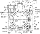
- FIG. 1 is a front view of a pipe retaining device according to a first embodiment of the present invention.
- FIG. 2 is a side view of FIG. 1 .
- FIG. 3 is a cross-sectional view taken along a line A-A in FIG. 1 .
- FIG. 4A is a perspective view of a retaining ring of the first embodiment.
- FIG. 4B is a perspective view of a flanged cap nut of the first embodiment.
- FIG. 5A is a diagram corresponding to FIG. 1 and showing a state after firm tightening of connecting means and before tightening of tightening means of the retaining ring.
- FIG. 5B is a side view of FIG. 5A .
- FIG. 5C is a cross-sectional view taken along a line B-B in FIG. 5A .
- FIG. 6A is a diagram corresponding to FIG. 1 and showing a state after firm tightening of the connecting means and before tightening of the tightening means of the retaining ring.
- FIG. 6B is a cross-sectional view taken along a line C-C in FIG. 6A .
- FIG. 7 is a diagram corresponding to FIG. 2 and showing a state where a pipe pulling force is applied to a joint pipe and the retaining ring is inclined.
- FIG. 8 is a front view of a pipe retaining device according to a second embodiment of the present invention.
- FIG. 9 is a side view of FIG. 8 .
- FIG. 10 is a perspective view of a retaining ring of the second embodiment.
- FIG. 11 is a diagram corresponding to FIG. 6A in the second embodiment.
- FIG. 12 is a diagram corresponding to FIG. 7 in the second embodiment.
- FIG. 13 is a front view of a pipe retaining device according to a third embodiment of the present invention.
- FIG. 14 is a side view of FIG. 13 .
- FIG. 15 is a perspective view of a retaining ring of the third embodiment.
- FIG. 16 is a diagram corresponding to FIG. 6A in the third embodiment.
- FIG. 17 is a diagram corresponding to FIG. 7 in the third embodiment.
- FIG. 18 is a front view of a pipe retaining device according to a fourth embodiment of the present invention.
- FIG. 19 is a side view of FIG. 18 .
- FIG. 20 is a perspective view of a retaining ring of the fourth embodiment.
- FIG. 21 is a diagram corresponding to FIG. 6A in the fourth embodiment.
- FIG. 22 is a diagram corresponding to FIG. 7 in the fourth embodiment.
- FIG. 23 is a front view of a pipe retaining device according to a fifth embodiment of the present invention.
- FIG. 24 is a side view of FIG. 23 .
- FIG. 25 is a perspective view of a retaining ring of the fifth embodiment.
- FIG. 26 is a diagram corresponding to FIG. 6A in the fifth embodiment.
- FIG. 27 is a diagram corresponding to FIG. 7 in the fifth embodiment.
- FIG. 28 is a side view showing a conventional pipe retaining device.
- a pipe retaining device 1 A roughly includes: a retaining ring 3 which is tightened and fixed to the outer peripheral surface of a joint pipe 100 by reducing the diameter of a ring body 30 A having a C-shaped ring shape by tightening means 9 ; a pressing ring 4 A which presses a packing 6 against a receiving portion 21 of a fitting body 2 ; connecting means 5 which connects and fixes the retaining ring 3 A and the pressing ring 4 A to the fitting body 2 ; and an inclination mechanism 7 which will be described later.
- the joint pipe 100 is, for example, a high-performance polyethylene pipe (also referred to as Higher Performance Polyethylene, commonly known as “HPPE”, or “third generation high-density polyethylene pipe”), and the nominal diameter thereof is 150.
- a high-performance polyethylene pipe also referred to as Higher Performance Polyethylene, commonly known as “HPPE”, or “third generation high-density polyethylene pipe”
- HPPE Higher Performance Polyethylene
- the pipe retaining device 1 improves the holding force (detachment preventing force) for the pipe and also improves workability without hindering the diameter reduction.
- MRS minimum required strength
- the long-term hydrostatic strength is a circumferential stress value that allows the pipe to withstand use at 20° for 50 years, and is calculated (predicted) on the basis of data of an internal pressure creep test.
- a detachment preventing force for the pipe which further exceeds the specified test load specified for each nominal diameter with respect to pipe strength is ensured.
- a pipe detachment preventing force equal to or greater than the pipe strength for a high-performance polyethylene pipe a pipe having a pipe detachment preventing force of 40 kN or more in the case of a nominal diameter of 75, a pipe having a pipe detachment preventing force of 77 kN or more in the case of a nominal diameter of 100, and a pipe having a pipe detachment preventing force of 160 kN or more in the case of a nominal diameter of 150 correspond to type 1, and are classified as pipes for which the joint strength is equal to or higher than the pipe strength.
- the high-performance polyethylene pipe is usually not used as an exposed pipe but is used as a buried pipe. Therefore, the pipe is not bent and deformed by the normal use pressure (0.75 MPa) or the water pressure of a water pressure leak test (0.5 MPa or less) after construction.
- the fitting body 2 has the receiving portion 21 having a tapered shape, and a cavity 22 for positioning an end portion of the joint pipe 100 therein, and a flange 23 having a substantially rectangular shape is provided on the outer periphery of the fitting body 2 .
- a through hole 24 through which a first penetrating member 51 , which will be described later, is inserted is formed at each of the four corners of the flange 23 .
- the retaining ring 3 A roughly includes the ring body 30 A, a pair of projecting pieces 31 , 31 provided at both circumferential end portions 30 x , 30 x of the ring body 30 A, and a plurality of retaining ring connecting portions 32 arranged at appropriate intervals along the circumferential direction of the ring body 30 A.
- Each projecting piece 31 has a through hole 31 a through which a bolt 9 a of the tightening means 9 is caused to extend.
- the retaining ring connecting portions 32 include first retaining ring connecting portions 32 a adjacent to the projecting piece 31 , and second retaining ring connecting portions 32 b which are farther from the projecting piece 31 than the first retaining ring connecting portions 32 a are, and are provided in a pair so as to be line-symmetrical with respect to a center line L connecting a central axis C of the retaining ring 3 A and a circumferential center portion 30 y.
- the first and second retaining ring connecting portions 32 a and 32 b are provided with elongated holes 33 a and 33 b as retaining ring penetration portions 33 through which second penetrating members 52 , which will be described later, are caused to extend.
- a longitudinal direction D 1 of the elongated hole 33 a of each first retaining ring connecting portion 32 a (a center line d 1 of the elongated hole 33 a ) is oriented toward the projecting piece 31 and intersects the center line L.
- a longitudinal direction D 2 of the elongated hole 33 b of each second retaining ring connecting portion 32 b is parallel to the center line L.
- first and second ribs 37 and 38 are provided on the outer surface of the ring body 30 A so as to project outward.
- Each first rib 37 is provided between the first retaining ring connecting portion 32 a and the second retaining ring connecting portion 32 b , and is formed so as to be gradually thinner (lower) from the first retaining ring connecting portion 32 a toward the second retaining ring connecting portion 32 b .
- the second rib 38 is provided between a pair of the second retaining ring connecting portions 32 b , 32 b , and is formed with a uniform wall thickness (height).
- the diameter of the ring body 30 A is reduced by the tightening means 9 substantially uniformly in the circumferential direction.
- a plurality of tooth portions 39 which bite into the joint pipe 100 due to the diameter reduction of the ring body 30 A by the tightening means 9 are formed on the inner peripheral surface of the ring body 30 A along the circumferential direction.
- the pressing ring 4 A includes a main body 40 having an annular shape, and first and second pressing ring connecting portions 42 a and 42 b which protrude outward from the main body 40 and which face the first and second retaining ring connecting portions 32 a and 32 b in a pipe axis direction X.
- a circular pressing ring through hole 43 through which the first penetrating member 51 is caused to extend is provided at each of the centers of the first and second pressing ring connecting portions 42 a and 42 b .
- the first and second pressing ring connecting portions 42 a and 42 b have the same shape, and are provided at equal intervals of approximately 90° so as to be rotationally symmetrical with respect to the center of the pressing ring 4 A.
- the longitudinal direction D 1 of the elongated hole 33 a corresponds to a straight line connecting the positions of the through hole 43 of the first pressing ring connecting portion 42 a with respect to the ring body 30 A before and after tightening the retaining ring 3 A.
- the longitudinal direction D 2 of the elongated hole 33 b corresponds to a straight line connecting the positions of the through hole 43 of the second pressing ring connecting portion 42 b with respect to the ring body 30 A before and after tightening the retaining ring 3 A.
- each connecting means 5 roughly includes the first penetrating member 51 which extends through the through hole 24 of the fitting body 2 and the pressing ring through hole 43 , and the second penetrating member 52 which includes: a connection portion 53 extending through the retaining ring penetration portion 33 (elongated hole 33 a or 33 b ) and connected to the first penetrating member 51 ; and a facing portion 54 facing the retaining ring connecting portion 32 (first or second retaining ring connecting portion 32 a or 32 b ) in the pipe axis direction X.
- the first penetrating member 51 is a T-shaped bolt
- the second penetrating member 52 is a flanged cap nut.
- the connection portion 53 is a cylindrical portion inside of which a thread groove 53 a is formed
- the facing portion 54 is a ring-shaped flange portion protruding outward from the cylindrical portion 53 .
- each connecting means 5 further includes a washer 55 as a contact member through which the T-shaped bolt 51 extends and which comes into contact with the cylindrical portion 53 and the pressing ring connecting portion 42 .
- the pressing ring 4 is fixed to the fitting body 2 by the connecting means 5 before tightening the ring body 30 A (reducing the diameter of the retaining ring 3 ( FIG. 5C ).
- the centers of the T-shaped bolt 51 and the pressing ring through hole 43 may be displaced relative to each other.
- the contact area of the flanged cap nut 52 with respect to the pressing ring connecting portion 42 is wider (larger) than that when an end portion 53 b of the cylindrical portion 53 is brought into direct contact with the pressing ring connecting portion 42 .
- the flanged cap nut 52 is screwed to the T-shaped bolt 51 , the surface of the pressing ring connecting portion 42 is not scratched by the rotation of the cylindrical portion 53 . Moreover, the washer 55 is merely compressed without rotating together with the flanged cap nut 52 . Therefore, even if the flanged cap nut 52 comes into contact with the retaining ring penetration portion 33 when the retaining ring 3 A is tightened, the flanged cap nut 52 to which the T-shaped bolt 51 has been screwed slides smoothly due to the washer 55 , and does not hinder the diameter reduction of the retaining ring 3 A.
- the inclination mechanism 7 inclines the retaining ring 3 A in the pipe axis direction X with respect to a reference plane P orthogonal to the central axis C of the ring body 30 A, such that each circumferential end portion 30 x of the ring body 30 A is caused to be closer to the fitting body 2 and the circumferential center portion 30 y is moved away from the fitting body 2 .
- the inclination mechanism 7 inclines the retaining ring 3 A toward a horizontal plane N which includes the central axis C of the ring body 30 A and which is orthogonal to the center line L connecting a center O of the ring body 30 A and the circumferential center portion 30 y .
- the pipe since the high-performance polyethylene pipe is used as a buried pipe, the pipe is not bent and deformed by the normal use pressure or in a water pressure leak test. That is, the inclination mechanism 7 functions when a large pulling force is generated at the pipe in a normal use state.
- each of first surfaces 56 (facing plane Q shown by an alternate long and short dash line in FIG. 5B ), facing the respective retaining ring connecting portions 32 a and 32 b , of the flange portions 54 is parallel to the reference plane P.
- second surfaces 34 a and 34 b facing the flange portions 54 , of the first and second retaining ring connecting portions 32 a and 32 b are located within the same inclined plane PI inclined in the pipe axis direction X at an inclination angle ⁇ with respect to the reference plane P.
- the inclination mechanism 7 includes the second surfaces 34 a and 34 b of the retaining ring connecting portions 32 (first and second retaining ring connecting portions 32 a and 32 b ) (inclined plane PI) and the first surfaces 56 of the flange portions (facing portions) 54 .
- an interval B between the first surface 56 and the inclined plane PI becomes larger from the circumferential end portions 30 x toward the circumferential center portion 30 y . It should be noted that in FIG. 5B , each first surface 56 is located within the same facing plane Q.
- the fitting body 2 side of the ring body 30 at the circumferential center portion 30 y tries to bite into the joint pipe 100 due to the inclination of the retaining ring 3 , and thus the amount by which the tooth portions 39 at the circumferential center portion 30 y bite is decreased (the teeth are raised). Then, when the pipe pulling force F further acts, the joint pipe 100 is displaced relative to the retaining ring 3 A on the circumferential center portion 30 y side. Therefore, the effect of improving the detachment preventing force for the pipe due to the inclination of the retaining ring 3 is small as compared to the present embodiment.
- the inclination mechanism 7 of the present invention causes each circumferential end portion 30 x of the ring body 30 A to be closer to the fitting body 2 and also moves the circumferential center portion 30 y away from the fitting body 2 .
- the inclined plane PI is inclined at an inclination angle ⁇ that is greater than 0° and not greater than 5° with respect to the reference plane P.
- the inclination angle ⁇ is not less than 1° and not greater than 5°.
- the inclination angle is not less than 2° and not greater than 3°.
- the maximum load was 171.9 kN in the case of an inclination angle of 0°.
- the maximum load was 177.2 kN at an inclination angle of 2°, and the maximum load was 184.4 kN at an inclination angle of 3°.
- the maximum load was 171.8 kN.
- a pipe that is classified as type 1 in the UK water industry standard is a pipe that has a pipe detachment preventing force of 160 kN or more with a nominal diameter of 150.
- 171.8 ⁇ 160 11.8 kN.
- 184.4 ⁇ 160 24.4 kN, so that the pipe detachment prevention ability which is more than twice that of the conventional product and which has a margin is ensured.
- FIGS. 1 to 3 show the pipe retaining device 1 A in which an opening nut 9 c is mounted on the pair of projecting pieces 31 , 31 .
- This state is a state before tightening the retaining ring 3 A (before diameter reduction) and before firmly tightening the connecting means 5 (before completion of screwing with the thread groove 53 a ).
- the fitting body 2 and the pressing ring 4 A are not in contact with each other, and the packing 6 does not become deformed.
- the tooth portions 39 of the retaining ring 3 A do not bite into the joint pipe 100 .
- each flanged cap nut 52 is firmly tightened (finally tightened) to the T-shaped bolt 51 to connect the retaining ring 3 A and the pressing ring 4 A to the fitting body 2 (screwing with the thread groove 53 a is completed).
- the end portion 53 b of each cylindrical portion 53 comes into contact with the washer 55 , and the pressing ring 4 A presses the packing 6 against the receiving portion 21 to compress and deform the packing 6 and also comes into contact with the fitting body 2 .
- the retaining ring 3 A has not been tightened yet.
- the central axes of the respective connecting means 5 located at one ends of the elongated holes 33 a and 33 b of the retaining ring 3 A coincide with the centers of the respective through holes 43 of the pressing ring connecting portions 42 a and 42 b .
- the center of the retaining ring 3 A and the center of the pressing ring 4 A also coincide with each other.
- a maximum width (length) W 1 in the pipe axis direction of each retaining ring connecting portion 32 is shorter than a length W 2 of the cylindrical portion 53 (distance from the flange portion 54 to the cylindrical portion end portion 53 b ).
- a gap S is formed between the flange portions 54 and the first and second pressing ring connecting portions 42 a and 42 b at the first and second retaining ring connecting portions 32 a and 32 b . Therefore, it is not necessary to manually tighten (temporarily tighten) the connecting means 5 to temporarily fix the pipe before tightening and fixing the tightening means 9 of the retaining ring 3 A as in the conventional art, and it is sufficient that the pressing ring 4 A is merely firmly tightened (finally tightened), so that the work is simple, and the workability is good.
- the diameter reduction of the ring body 30 A is guided along the oriented directions (longitudinal directions D 1 and D 2 ) of the elongated holes 33 a and 33 b , and the first and second retaining ring connecting portions 32 a and 32 b move so as to follow the diameter reduction of the ring body 30 A.
- the central axes of the respective connecting means 5 having moved from one ends to the other ends of the elongated holes 33 a and 33 b coincide with the centers of the respective through holes 43 of the pressing ring connecting portions 42 a and 42 b .
- the center of the retaining ring 3 A reduced in diameter by tightening and the center of the pressing ring 4 A also coincide with each other. Therefore, the connecting means 5 does not hinder the diameter reduction, and a load is not locally applied to the ring body 30 A to cause cracks or the like.
- the retaining ring connecting portions 32 and the pressing ring connecting portions 42 do not come into contact with each other when the diameter of the ring body 30 A is reduced, so that no frictional resistance due to contact is generated. Therefore, the diameter reduction can be performed smoothly with low torque, so that the workability is good. Furthermore, since the retaining ring 3 A is not fixed to the fitting body 2 , and the first and second retaining ring connecting portions 32 a and 32 b and the flange portions 54 are separated from each other, the joint pipe 100 can be stretched and contracted.
- the space (interval B) formed at the first surface 56 of the flange portion 54 of the flanged cap nut 52 is larger at the second surface 34 b of each second retaining ring connecting portion 32 b than at the second surface 34 a of each first retaining ring connecting portion 32 a , and is larger at the lower portion (circumferential center portion 30 y ) than at the upper portion (circumferential end portion 30 x side).
- a space (gap) is formed such that the interval B therebetween becomes larger from the circumferential end portions 30 x toward the circumferential center portion 30 y .
- the biting of the tooth portions 39 is shallow in the vicinity of the circumferential center portion 30 y .
- slip of the joint pipe 100 occurs at this portion, so that the pipe detachment preventing force is decreased.
- the retaining ring 3 A can be relatively easily inclined to form the deformed portion M in the joint pipe 100 , so that the detachment preventing force for the pipe can be further improved.
- the tooth portions 39 at the circumferential center portion 30 y further bite into the joint pipe 100 , so that the pipe detachment preventing force is further improved.
- the second surfaces 34 a and 34 b of the retaining ring connecting portion 32 are formed as flat surfaces and forming the first surfaces 56 of the flange portions 54 as inclined surfaces, it is also conceivable to incline the retaining ring 3 A in the same manner as described above to deform the joint pipe 100 .
- FIGS. 8 to 12 a second embodiment of the present invention will be described with reference to FIGS. 8 to 12 . It should be noted that the same members as those of the above-described embodiment are designated by the same reference characters.
- connection to the fitting body 2 is made by the connecting means 5 at the retaining ring connecting portions 32 (first and second retaining ring connecting portions 32 a and 32 b ) at the four locations.
- the retaining ring connecting portions 32 of a retaining ring 3 B according to the second embodiment include a pair of first retaining ring connecting portions 32 a , 32 a and one second retaining ring connecting portion 32 b 1 at three locations.
- the nominal diameter of the joint pipe 100 is, for example, 100.
- the second retaining ring connecting portion 32 b 1 is located at the circumferential center portion 30 y of a ring body 30 B, and a recess 33 b 1 is formed therein as a second retaining ring penetration portion so as to be open on one side thereof.
- the recess 33 b 1 has a smaller width than the flange portion 54 and extends along the center line L.
- the second surfaces 34 a and 34 b , facing the flange portions 54 , of the first and second retaining ring connecting portions 32 a and 32 b 1 are located within the same inclined plane PI inclined in the pipe axis direction X at an inclination angle ⁇ with respect to the reference plane P.
- the inclined plane PI is inclined at an inclination angle ⁇ that is greater than 0° and not greater than 5° with respect to the reference plane P.
- the inclination angle ⁇ is not less than 1° and not greater than 5°.
- the space (interval B) formed at the first surface 56 of the flange portion 54 of the flanged cap nut 52 is larger at the second surface 34 b of the second retaining ring connecting portion 32 b 1 than at the second surface 34 a of each first retaining ring connecting portion 32 a , and is larger at the lower portion (circumferential center portion 30 y ) than at the upper portion (circumferential end portion 30 x side).
- the tightening means 9 of the retaining ring 3 B can be tightened to reduce the diameter of the ring body 30 B.
- the flanged cap nuts 52 slide along the longitudinal direction D 1 within the elongated holes 33 a .
- the connecting means 5 does not hinder the diameter reduction and does not come off from the recess 33 b 1 .
- an elongated hole may be formed along the center line L.
- the retaining ring 3 B is inclined with the upper ends 56 a as a base due to the interval B (space) and the inclined plane PI (second surfaces 34 a and 34 b ) shown in FIG. 9 . Then, the ring body 30 B comes into contact with the joint pipe 100 to deform (bend) the joint pipe 100 .
- a formed deformed portion M opposes the pipe pulling force F, and the tooth portions 39 at the circumferential center portion 30 y further bite into the joint pipe 100 , so that it is possible to greatly improve the detachment preventing force for the pipe.
- the retaining ring connecting portions 32 of a retaining ring 3 C include only a pair of first retaining ring connecting portions 32 a 2 and 32 a 2 at two locations.
- the nominal diameter of the joint pipe 100 is, for example, 50 or 75.
- the pair of first retaining ring connecting portions 32 a 2 and 32 a 2 are each located at an intermediate portion between the circumferential center portion 30 y and the circumferential end portion 30 x of a ring body 30 C, and are arranged so as to be line-symmetrical with respect to the center line L.
- a recess 33 a 2 is formed as a first retaining ring penetration portion in each first retaining ring connecting portion 32 a 2 so as to be open on the outer side thereof.
- the recess 33 a 2 has a smaller width than the flange portion 54 .
- the second surfaces 34 , facing the flange portions 54 , of the first retaining ring connecting portions 32 a 2 are located within the same inclined plane PI inclined in the pipe axis direction X at an inclination angle ⁇ with respect to the reference plane P.
- the inclined plane PI is inclined at an inclination angle ⁇ that is greater than 0° and not greater than 10° with respect to the reference plane P.
- the inclination angle ⁇ is not less than 1° and not greater than 6°.
- the space (interval B) formed between the first surface 56 of the flange portion 54 of the flanged cap nut 52 and the second surface 34 of the first retaining ring connecting portion 32 a 2 is larger at the lower portion (circumferential center portion 30 y ) than at the upper portion (circumferential end portion 30 x side).
- the tightening means 9 of the retaining ring 3 C can be tightened to reduce the diameter of the ring body 30 C.
- the flanged cap nuts 52 slide along the center line L within the recesses 33 a 2 . Therefore, the connecting means 5 does not hinder the diameter reduction and does not come off from each recess 33 a 2 .
- an elongated hole may be formed along the center line L.
- the opening width of the recess 33 a 2 and the width of the inner portion of the recess 33 a 2 are equal to each other, but the recess 33 a 2 may be formed such that the opening width is smaller than the width of the inner portion (the shape of the recess is substantially a C-shape as viewed in the pipe axis direction).
- the shape of the recess 33 a 2 is not limited to the shape in the present embodiment as long as the shape is a shape that allows the flanged cap nut 52 to slide within the recess 33 a 2 .
- the retaining ring 3 C is inclined with the upper ends 56 a as a base due to the interval B (space) and the inclined plane PI (second surfaces 34 a ) shown in FIG. 14 . Then, the ring body 30 C comes into contact with the joint pipe 100 to deform (bend) the joint pipe 100 .
- a formed deformed portion M opposes the pipe pulling force F, and the tooth portions 39 at the circumferential center portion 30 y further bite into the joint pipe 100 , so that it is possible to greatly improve the detachment preventing force for the pipe.
- the retaining ring connecting portions 32 of a retaining ring 3 D include a pair of first retaining ring connecting portions 32 a , 32 a , a pair of second retaining ring connecting portions 32 b 2 , 32 b 2 , and a pair of third retaining ring connecting portions 32 c , 32 c at six locations, and the respective connecting portions are arranged in pairs so as to be line-symmetrical with respect to the center line L.
- the nominal diameter of the joint pipe 100 is, for example, 250.
- each second retaining ring connecting portion 32 b 2 is located in the vicinity of the circumferential center portion 30 y of a ring body 30 D.
- each third retaining ring connecting portion 32 c is provided at the center between the first retaining ring connecting portion 32 a and the second retaining ring connecting portion 32 b 2 (position shifted by 90° in the circumferential direction of the ring body 30 from the circumferential center portion 30 y of the ring body 30 C).
- the second retaining ring connecting portions 32 b 2 and the third retaining ring connecting portions 32 c are provided with elongated holes 33 b 2 and 33 c having a smaller width than the flange portion 54 .
- the first retaining ring connecting portions 32 a have the same configuration as in the above first embodiment.
- the longitudinal direction D 1 (center line d 1 ) of the elongated hole 33 a of each first retaining ring connecting portion 32 a and a longitudinal direction D 3 (center line d 3 ) of the elongated hole 33 c of each third retaining ring connecting portion 32 c are oriented toward the projecting piece 31 and intersect the center line L.
- an intersection angle ⁇ l of the center line d 1 with respect to the center line L is larger than the intersection angle of the center line d 3 with respect to the center line L.
- the longitudinal direction D 2 (center line d 2 ) of the elongated hole 33 b 2 of each second retaining ring connecting portion 32 b 2 is oriented toward the third retaining ring connecting portion 32 c , and the oriented direction thereof is opposite to those of the above center lines d 1 and d 3 .
- the center line d 2 is substantially parallel to the center line L, and thus the intersection angle thereof with respect to the center line L is very small as compared to the intersection angle of the center line d 3 with respect to the center line L.
- the second surfaces 34 a , 34 b , and 34 c , facing the flange portions 54 , of the respective retaining ring connecting portions 32 a , 32 b 2 , and 32 c are located within the same inclined plane PI inclined in the pipe axis direction X at an inclination angle ⁇ with respect to the reference plane P. It should be noted that it is sufficient that the inclined plane PI is inclined at an inclination angle ⁇ that is greater than 0° and not greater than 5° with respect to the reference plane P. Preferably, the inclination angle ⁇ is not less than 1° and not greater than 4°.
- the space (interval B) formed between each retaining ring connecting portion (inclined plane PI) and the first surface 56 of the flange portion 54 is larger in the order of the second surface 34 a of each first retaining ring connecting portion 32 a , the second surface 34 c of each third retaining ring connecting portion 32 c , and the second surface 34 b of each second retaining ring connecting portion 32 b 2 , and is larger at the lower portion (circumferential center portion 30 y ) than at the upper portion (circumferential end portion 30 x side).
- the tightening means 9 of the retaining ring 3 D can be tightened to reduce the diameter of the ring body 30 D.
- the central axes of the connecting means 5 located at one ends of the elongated holes 33 a , 33 b 2 , and 33 c of the retaining ring 3 D coincide with the centers of the respective through holes of the pressing ring connecting portions 42 a , 42 b , and 42 c .
- the center of the retaining ring 3 D and the center of the pressing ring 4 D also coincide with each other. Then, when the retaining ring 3 D is tightened by the tightening means 9 , the flanged cap nuts 52 slide along the respective longitudinal directions D 1 to D 3 within the elongated holes 33 a , 33 b 2 , and 33 c .
- the diameter reduction of the ring body 30 D is guided along the oriented directions (longitudinal directions D 1 , D 2 , and D 3 ) of the elongated holes 33 a , 33 b 2 , and 33 c , and the respective retaining ring connecting portions 32 a , 32 b 2 , and 32 c move so as to follow the diameter reduction of the ring body 30 D.
- the central axes of the respective connecting means 5 having moved from one ends to the other ends of the elongated holes 33 a , 33 b 2 , and 32 c coincide with the centers of the respective through holes of the pressing ring connecting portions 42 a , 42 b , and 42 c .
- the center of the retaining ring 3 D reduced in diameter by tightening and the center of the pressing ring 4 D also coincide with each other. Therefore, the connecting means 5 does not hinder the diameter reduction, and a load is not locally applied to the ring body 30 D to cause cracks or the like.
- the retaining ring 3 D is inclined with the upper ends 56 a as a base due to the interval B (space) and the inclined plane PI (second surfaces 34 a , 34 b , and 34 c ). Then, the ring body 30 D comes into contact with the joint pipe 100 to deform (bend) the joint pipe 100 .
- a formed deformed portion M opposes the pipe pulling force F, and the tooth portions 39 at the circumferential center portion 30 y further bite into the joint pipe 100 , so that it is possible to greatly improve the detachment preventing force for the pipe.
- the retaining ring connecting portions 32 of a retaining ring 3 E include a pair of first retaining ring connecting portions 32 a , 32 a , a second retaining ring connecting portion 32 b 3 located at the circumferential center portion 30 y of a ring body 30 E, and a pair of third retaining ring connecting portions 32 c 1 , 32 c 1 at five locations, and the respective connecting portions are arranged in pairs so as to be line-symmetrical with respect to the center line L.
- the nominal diameter of the joint pipe 100 is, for example, 250 or 300.
- each third retaining ring connecting portion 32 c 1 is provided at the middle (center) between the first retaining ring connecting portion 32 a and the second retaining ring connecting portion 32 b 3 .
- the second retaining ring connecting portion 32 b 3 and the third retaining ring connecting portions 32 c 1 are provided with elongated holes 33 b 3 and 33 c 1 having a smaller width than the flange portion 54 .
- the first retaining ring connecting portions 32 a have the same configuration as in the above second embodiment.
- the longitudinal direction D 1 (center line d 1 ) of the elongated hole 33 a of each first retaining ring connecting portion 32 a and a longitudinal direction D 3 (center line d 3 ) of the elongated hole 33 c 1 of each third retaining ring connecting portion 32 c 1 are oriented toward the projecting piece 31 and intersect the center line L.
- an intersection angle ⁇ 1 of the center line d 1 with respect to the center line L is larger than the intersection angle of the center line d 3 with respect to the center line L.
- the longitudinal direction D 2 (center line d 2 ) of the elongated hole 33 bb of the second retaining ring connecting portion 32 b 3 coincides with the center line L.
- the second surfaces 34 a , 34 b , and 34 c , facing the flange portions 54 , of the respective retaining ring connecting portions 32 a , 32 b 3 , and 32 c 1 are located within the same inclined plane PI inclined in the pipe axis direction X at an inclination angle ⁇ with respect to the reference plane P. It should be noted that it is sufficient that the inclined plane PI is inclined at an inclination angle ⁇ that is greater than 0° and not greater than 5° with respect to the reference plane P. Preferably, the inclination angle ⁇ is not less than 1° and not greater than 4°.
- the space (interval B) formed between each retaining ring connecting portion (inclined plane PI) and the first surface 56 of the flange portion 54 is larger in the order of the second surface 34 a of each first retaining ring connecting portion 32 a , the second surface 34 c of each third retaining ring connecting portion 32 c , and the second surface 34 b of the second retaining ring connecting portion 32 b 3 , and is larger at the lower portion (circumferential center portion 30 y ) than at the upper portion (circumferential end portion 30 x side).
- the tightening means 9 of the retaining ring 3 E can be tightened to reduce the diameter of the ring body 30 E.
- the central axes of the connecting means 5 located at one ends of the elongated holes 33 a , 33 b 3 , and 33 c 1 of the retaining ring 3 E coincide with the centers of the respective through holes of the pressing ring connecting portions 42 a , 42 b , and 42 c .
- the center of the retaining ring 3 E and the center of the pressing ring 4 E also coincide with each other. Then, when the retaining ring 3 E is tightened by the tightening means 9 , the flanged cap nuts 52 slide along the respective longitudinal directions D 1 to D 3 within the elongated holes 33 a , 33 b 3 , and 33 c 1 .
- the diameter reduction of the ring body 30 E is guided along the oriented directions (longitudinal directions D 1 , D 2 , and D 3 ) of the elongated holes 33 a , 33 b 3 , and 33 c 1 , and the respective retaining ring connecting portions 32 a , 32 b 3 , and 33 c 1 move so as to follow the diameter reduction of the ring body 30 E.
- the central axes of the respective connecting means 5 having moved from one ends to the other ends of the elongated holes 33 a , 33 b 3 , and 33 c 1 coincide with the centers of the respective through holes of the pressing ring connecting portions 42 a , 42 b , and 42 c .
- the center of the retaining ring 3 E reduced in diameter by tightening and the center of the pressing ring 4 E also coincide with each other. Therefore, the connecting means 5 does not hinder the diameter reduction, and a load is not locally applied to the ring body 30 E to cause cracks or the like.
- the retaining ring 3 D is inclined with the upper ends 56 a as a base due to the interval B (space) and the inclined plane PI (second surfaces 34 a , 34 b , and 34 c ). Then, the ring body 30 E comes into contact with the joint pipe 100 to deform (bend) the joint pipe 100 .
- a formed deformed portion M opposes the pipe pulling force F, and the tooth portions 39 at the circumferential center portion 30 y further bite into the joint pipe 100 , so that it is possible to greatly improve the detachment preventing force for the pipe.
- High-performance polyethylene pipes include SDR13.6, SDR17, and SDR21 in addition to SDR11, depending on the relationship between pipe outer diameter and wall thickness, and the present invention can also be applied to these high-performance polyethylene pipes.
- the present invention can also be applied to crosslinked polyethylene pipes and polybuden pipes used as hot water pipes, etc.
- the third retaining ring connecting portions 33 c are provided between the first retaining ring connecting portions 32 a and the second retaining ring connecting portions 32 b 2 and these connection portions are provided so as to be line-symmetrical with respect to the center line L.
- the present invention is not limited thereto, and a plurality of pairs of third retaining ring connecting portions 32 c may be provided.
- a joint pipe having a larger bore diameter can be handled by using, for example, 8 or 10 first penetrating members (T-shaped bolts) 51 and 8 or 10 second penetrating members (flanged cap nuts) 52 such that these members are line-symmetrical with respect to the center line L.
- first retaining ring connecting portions 32 a , 32 a and one second retaining ring connecting portion 32 b 1 are provided.
- the present invention is not limited thereto, and a plurality of pairs of first retaining ring connecting portions 32 c may be provided.
- a joint pipe having a larger bore diameter can be handled by using, for example, 5 or 7 first penetrating members (T-shaped bolts) 51 and 5 or 7 second penetrating members (flanged cap nuts) 52 such that these members are line-symmetrical with respect to the center line L.
- an inner core is omitted, but the present invention can also be applied to the case of using an inner core.
- the inner core prevents the diameter of the joint pipe 100 from being reduced, but according to an experiment by the inventor, it was confirmed that when the pipe pulling force is increased, the retaining ring 3 is inclined by the inclination mechanism 7 and the joint pipe 100 and the fitting body 2 are maintained coaxially. That is, the present invention can be used (shared) regardless of whether or not the inner core is used, and the versatility is extremely high.
Landscapes
- Engineering & Computer Science (AREA)
- General Engineering & Computer Science (AREA)
- Mechanical Engineering (AREA)
- Joints With Sleeves (AREA)
- Quick-Acting Or Multi-Walled Pipe Joints (AREA)
Applications Claiming Priority (4)
| Application Number | Priority Date | Filing Date | Title |
|---|---|---|---|
| JP2019-202724 | 2019-11-07 | ||
| JP2019202724 | 2019-11-07 | ||
| JPJP2019-202724 | 2019-11-07 | ||
| PCT/JP2020/041610 WO2021090939A1 (ja) | 2019-11-07 | 2020-11-06 | 管継手の管抜止装置 |
Publications (2)
| Publication Number | Publication Date |
|---|---|
| US20220213990A1 US20220213990A1 (en) | 2022-07-07 |
| US11499655B2 true US11499655B2 (en) | 2022-11-15 |
Family
ID=75848128
Family Applications (1)
| Application Number | Title | Priority Date | Filing Date |
|---|---|---|---|
| US17/619,166 Active US11499655B2 (en) | 2019-11-07 | 2020-11-06 | Pipe retaining device for pipe fitting |
Country Status (6)
| Country | Link |
|---|---|
| US (1) | US11499655B2 (de) |
| EP (1) | EP3971460B1 (de) |
| JP (1) | JP6895702B1 (de) |
| CA (1) | CA3177359C (de) |
| DK (1) | DK3971460T3 (de) |
| WO (1) | WO2021090939A1 (de) |
Citations (4)
| Publication number | Priority date | Publication date | Assignee | Title |
|---|---|---|---|---|
| WO2015087802A1 (ja) | 2013-12-10 | 2015-06-18 | 株式会社川西水道機器 | 管継手の管抜止装置及びその施工方法 |
| JP2015190608A (ja) | 2014-03-28 | 2015-11-02 | 株式会社川西水道機器 | プラスチック管の離脱防止リング及びプラスチック管の管継手 |
| US20170211734A1 (en) * | 2015-12-17 | 2017-07-27 | Sk-Kawanishi Co., Ltd. | Pipe coupling device |
| JP2018109417A (ja) | 2016-12-28 | 2018-07-12 | 株式会社川西水道機器 | 管継手及び複層管の連結構造 |
-
2020
- 2020-11-06 DK DK20884430.8T patent/DK3971460T3/da active
- 2020-11-06 EP EP20884430.8A patent/EP3971460B1/de active Active
- 2020-11-06 CA CA3177359A patent/CA3177359C/en active Active
- 2020-11-06 JP JP2021506351A patent/JP6895702B1/ja active Active
- 2020-11-06 WO PCT/JP2020/041610 patent/WO2021090939A1/ja not_active Ceased
- 2020-11-06 US US17/619,166 patent/US11499655B2/en active Active
Patent Citations (5)
| Publication number | Priority date | Publication date | Assignee | Title |
|---|---|---|---|---|
| WO2015087802A1 (ja) | 2013-12-10 | 2015-06-18 | 株式会社川西水道機器 | 管継手の管抜止装置及びその施工方法 |
| US20160290538A1 (en) * | 2013-12-10 | 2016-10-06 | Sk-Kawanishi Co., Ltd. | Pipe coupling device and construction method therefor |
| JP2015190608A (ja) | 2014-03-28 | 2015-11-02 | 株式会社川西水道機器 | プラスチック管の離脱防止リング及びプラスチック管の管継手 |
| US20170211734A1 (en) * | 2015-12-17 | 2017-07-27 | Sk-Kawanishi Co., Ltd. | Pipe coupling device |
| JP2018109417A (ja) | 2016-12-28 | 2018-07-12 | 株式会社川西水道機器 | 管継手及び複層管の連結構造 |
Non-Patent Citations (1)
| Title |
|---|
| International Search Report issued in Application No. PCT/JP2020/041610, dated Dec. 28, 2020. |
Also Published As
| Publication number | Publication date |
|---|---|
| JPWO2021090939A1 (ja) | 2021-11-25 |
| EP3971460B1 (de) | 2023-06-28 |
| CA3177359A1 (en) | 2021-05-14 |
| JP6895702B1 (ja) | 2021-06-30 |
| DK3971460T3 (da) | 2023-09-18 |
| EP3971460A4 (de) | 2022-08-31 |
| WO2021090939A1 (ja) | 2021-05-14 |
| CA3177359C (en) | 2023-07-18 |
| EP3971460A1 (de) | 2022-03-23 |
| US20220213990A1 (en) | 2022-07-07 |
Similar Documents
| Publication | Publication Date | Title |
|---|---|---|
| US12129941B2 (en) | Coupling having arcuate stiffness ribs | |
| US11174972B2 (en) | Pipe joint | |
| US9746118B2 (en) | Method and structure for preventing slipping-off of a tube in a pipe joint made of fluororesin | |
| CA1202341A (en) | Union joint | |
| KR102817345B1 (ko) | 분해 방지 조인트 및 분해 방지 조인트 어셈블리 | |
| US20150021911A1 (en) | Fittings Having Arcuate Stiffness Ribs | |
| EP1262702B1 (de) | Verfahren und Vorrichtung zur Verhinderung des Abrutschens eines Rohres in einem Rohrverbindung aus Kunststoff | |
| US9879805B2 (en) | Pipe coupling device and construction method therefor | |
| WO2010001719A1 (ja) | プラスチック樹脂パイプ用の管継手 | |
| KR102815097B1 (ko) | 분해 방지 연결 부재 및 분해 방지 연결 어셈블리 | |
| JP4953463B2 (ja) | プラスチック樹脂パイプ用の管継手 | |
| KR20150009416A (ko) | 상수도용 배관의 연결장치 | |
| JP4766707B2 (ja) | プラスチック樹脂パイプ用の管継手 | |
| WO2015156198A1 (ja) | 管継手 | |
| US11499655B2 (en) | Pipe retaining device for pipe fitting | |
| US11473704B2 (en) | Pipe detachment preventing device for union nut pipe fitting | |
| JP2021175919A (ja) | 継手構造体 | |
| US11028950B2 (en) | Pipe coupling | |
| TWI762298B (zh) | 管接頭的管件固定裝置 | |
| JP4597889B2 (ja) | 管継手 | |
| JP2018017333A (ja) | 管継手 | |
| JPH0338551Y2 (de) | ||
| JPH04181090A (ja) | 管継手 | |
| JPH01145489A (ja) | 管継手 | |
| JPH01145488A (ja) | 管継手 |
Legal Events
| Date | Code | Title | Description |
|---|---|---|---|
| FEPP | Fee payment procedure |
Free format text: ENTITY STATUS SET TO UNDISCOUNTED (ORIGINAL EVENT CODE: BIG.); ENTITY STATUS OF PATENT OWNER: SMALL ENTITY |
|
| AS | Assignment |
Owner name: SK-KAWANISHI CO., LTD., JAPAN Free format text: ASSIGNMENT OF ASSIGNORS INTEREST;ASSIGNOR:KAWANISHI, HIDEHITO;REEL/FRAME:058398/0570 Effective date: 20210804 |
|
| FEPP | Fee payment procedure |
Free format text: ENTITY STATUS SET TO SMALL (ORIGINAL EVENT CODE: SMAL); ENTITY STATUS OF PATENT OWNER: SMALL ENTITY |
|
| STPP | Information on status: patent application and granting procedure in general |
Free format text: NON FINAL ACTION MAILED |
|
| STPP | Information on status: patent application and granting procedure in general |
Free format text: NOTICE OF ALLOWANCE MAILED -- APPLICATION RECEIVED IN OFFICE OF PUBLICATIONS |
|
| STPP | Information on status: patent application and granting procedure in general |
Free format text: PUBLICATIONS -- ISSUE FEE PAYMENT VERIFIED |
|
| STCF | Information on status: patent grant |
Free format text: PATENTED CASE |
|
| MAFP | Maintenance fee payment |
Free format text: PAYMENT OF MAINTENANCE FEE, 4TH YR, SMALL ENTITY (ORIGINAL EVENT CODE: M2551); ENTITY STATUS OF PATENT OWNER: SMALL ENTITY Year of fee payment: 4 |