EP3971460B1 - Rohrhaltevorrichtung für rohrverbindung - Google Patents
Rohrhaltevorrichtung für rohrverbindung Download PDFInfo
- Publication number
- EP3971460B1 EP3971460B1 EP20884430.8A EP20884430A EP3971460B1 EP 3971460 B1 EP3971460 B1 EP 3971460B1 EP 20884430 A EP20884430 A EP 20884430A EP 3971460 B1 EP3971460 B1 EP 3971460B1
- Authority
- EP
- European Patent Office
- Prior art keywords
- retaining ring
- pipe
- connecting portions
- ring connecting
- retaining
- Prior art date
- Legal status (The legal status is an assumption and is not a legal conclusion. Google has not performed a legal analysis and makes no representation as to the accuracy of the status listed.)
- Active
Links
Images


Classifications
-
- F—MECHANICAL ENGINEERING; LIGHTING; HEATING; WEAPONS; BLASTING
- F16—ENGINEERING ELEMENTS AND UNITS; GENERAL MEASURES FOR PRODUCING AND MAINTAINING EFFECTIVE FUNCTIONING OF MACHINES OR INSTALLATIONS; THERMAL INSULATION IN GENERAL
- F16L—PIPES; JOINTS OR FITTINGS FOR PIPES; SUPPORTS FOR PIPES, CABLES OR PROTECTIVE TUBING; MEANS FOR THERMAL INSULATION IN GENERAL
- F16L21/00—Joints with sleeve or socket
- F16L21/08—Joints with sleeve or socket with additional locking means
-
- F—MECHANICAL ENGINEERING; LIGHTING; HEATING; WEAPONS; BLASTING
- F16—ENGINEERING ELEMENTS AND UNITS; GENERAL MEASURES FOR PRODUCING AND MAINTAINING EFFECTIVE FUNCTIONING OF MACHINES OR INSTALLATIONS; THERMAL INSULATION IN GENERAL
- F16L—PIPES; JOINTS OR FITTINGS FOR PIPES; SUPPORTS FOR PIPES, CABLES OR PROTECTIVE TUBING; MEANS FOR THERMAL INSULATION IN GENERAL
- F16L21/00—Joints with sleeve or socket
- F16L21/06—Joints with sleeve or socket with a divided sleeve or ring clamping around the pipe ends
- F16L21/065—Joints with sleeve or socket with a divided sleeve or ring clamping around the pipe ends tightened by tangentially-arranged threaded pins
Definitions
- the present invention relates to a pipe retaining device for a pipe fitting. More specifically, the present invention relates to a pipe retaining device, for a pipe fitting, which includes: a retaining ring tightened and fixed to the outer peripheral surface of a joint pipe by reducing the diameter of a ring body having a C-shaped ring shape by tightening means; a pressing ring configured to press a packing against a receiving portion of a fitting body; and connecting means configured to connect the retaining ring and the pressing ring to the fitting body.
- WO 2015/087802 A1 discloses a pipe coming-off prevention device for a pipe joint and a construction method therefor and JP 2018 109417 A discloses a pipe joint and a connection structure of a multi-layer pipe.
- an object of the present invention is to provide a pipe retaining device, for a pipe fitting, which has a simple structure but is capable of further improving a detachment preventing force for a pipe without inserting an inner core.
- a pipe retaining device for a pipe fitting comprising: a retaining ring which comprises a ring body having a C-shaped ring shape, tightening means, a pressing ring, a packing, connecting means, and a fitting body comprising a receiving portion, wherein the retaining ring can be tightened and fixed to an outer peripheral surface of a joint pipe by reducing a diameter of the ring body having the C-shaped ring shape by the tightening means; wherein the pressing ring is configured to press the packing against the receiving portion of the fitting body; and the connecting means is configured to connect the retaining ring and the pressing ring to the fitting body, wherein the retaining ring includes a pair of projecting pieces which are provided at both circumferential end portions of the ring body and each of which has a through hole through which the tightening means is caused to extend, a tooth portion which is provided on an inner side of the ring body and which bites into the joint pipe due to diameter reduction by the tightening means, and
- the pipe retaining device includes an inclination mechanism configured to incline the retaining ring in the pipe axis direction with respect to a reference plane orthogonal to a central axis of the ring body, such that each circumferential end portion of the ring body is caused to be closer to the fitting body and a circumferential center portion of the ring body is moved away from the fitting body, when each retaining ring connecting portion and each facing portion come into contact with each other in a state where the diameter of the ring body is reduced by the tightening means, a first surface, facing the retaining ring connecting portion, of each facing portion is parallel to the reference plane, second surfaces, facing the facing portions, of the plurality of retaining ring connecting portions are located within the same inclined plane inclined in the pipe axis direction with respect to the reference plane, and an interval between the first surface and the inclined plane becomes larger from the circumferential end portions toward the circumferential center portion.
- the connecting means includes first penetrating members each of which extends through a through hole of the fitting body and the pressing ring through hole, and second penetrating members each of which includes a connection portion extending through the retaining ring penetration portion and connected to the first penetrating member and a facing portion facing the retaining ring connecting portion in the pipe axis direction.
- a first surface, facing the retaining ring connecting portion, of each facing portion is parallel to a reference plane orthogonal to a central axis of the ring body
- second surfaces, facing the facing portions, of the plurality of retaining ring connecting portions are located within the same inclined plane inclined in the pipe axis direction with respect to the reference plane, and an interval between the first surface and the inclined plane becomes larger from the circumferential end portions toward the circumferential center portion.
- the tooth portion of the retaining ring bites into the joint pipe more on the circumferential end portion side where the tightening means is located, than the circumferential center portion side of the ring body, so that a greater pipe detachment preventing force is generated on the circumferential end portion side than at the circumferential center portion. Therefore, when a pipe pulling force is applied to the joint pipe, the joint pipe is stretched more on the circumferential end portion side than at the circumferential center portion, and each retaining ring connecting portion and each facing portion come into contact with each other.
- the inclination mechanism inclines the retaining ring in the pipe axis direction with respect to the reference plane such that each circumferential end portion of the ring body is caused to be closer to the fitting body and the circumferential center portion of the ring body is moved away from the fitting body. Accordingly, the ring body bites on each of the circumferential end portion side and the circumferential center portion side of the joint pipe to deform (bend) the joint pipe. The deformation of the joint pipe becomes a large resistance to the pipe pulling force.
- the amount by which the tooth portion in the vicinity of the circumferential center portion bites also increases. Therefore, the deformation of the ring body and the biting of the tooth portion into the pipe become a large resistance to the pipe pulling force, so that it is possible to significantly improve the detachment preventing force for the pipe.
- the plurality of retaining ring connecting portions may include a pair of first retaining ring connecting portions adjacent to the pair of projecting pieces, and a pair of second retaining ring connecting portions adjacent to the pair of first retaining ring connecting portions, the pair of first retaining ring connecting portions and the pair of second retaining ring connecting portions may be arranged so as to be line-symmetrical with respect to a center line connecting the central axis and the circumferential center portion, first retaining ring penetration portions of the first retaining ring connecting portions may each be an elongated hole in which the connection portion is slidable along the circumferential direction of the ring body and which has a smaller width than the facing portion, and second retaining ring penetration portions of the second retaining ring connecting portions may each be an elongated hole in which the connection portion is slidable in a direction along the center line and which has a smaller width than the facing portion.
- the retaining ring penetration portions of the first retaining ring connecting portions are each an elongated hole in which the connection portion is slidable along the circumferential direction of the ring body and which has a smaller width than the facing portion
- the second retaining ring penetration portions of the second retaining ring connecting portions are each an elongated hole in which the connection portion is slidable in a direction along the center line and which has a smaller width than the facing portion.
- the plurality of retaining ring connecting portions may include a pair of first retaining ring connecting portions adjacent to the pair of projecting pieces, and a second retaining ring connecting portion located at the circumferential center portion, the pair of first retaining ring connecting portions may be arranged so as to be line-symmetrical with respect to a center line connecting the central axis and the circumferential center portion, first retaining ring penetration portions of the first retaining ring connecting portions may each be an elongated hole in which the connection portion is slidable along the circumferential direction of the ring body and which has a smaller width than the facing portion, and a second retaining ring penetration portion of the second retaining ring connecting portion may each be a recess which is open on one side thereof or a hole which has a smaller width than the facing portion and in which the connection portion is slidable in a direction along the center line.
- the retaining ring penetration portions of the first retaining ring connecting portions are each an elongated hole in which the connection portion is slidable along the circumferential direction of the ring body and which has a smaller width than the facing portion
- the second retaining ring penetration portion of the second retaining ring connecting portion is a recess which is open on one side thereof or a hole which has a smaller width than the facing portion and in which the connection portion is slidable in a direction along the center line.
- the plurality of retaining ring connecting portions may include a pair of retaining ring connecting portions each located at an intermediate portion between the circumferential center portion and the circumferential end portion of the ring body, the pair of retaining ring connecting portions may be arranged so as to be line-symmetrical with respect to a center line connecting the central axis and the circumferential center portion, and retaining ring penetration portions of the retaining ring connecting portions may each be a recess which is open on one side thereof or an elongated hole which has a smaller width than the facing portion and in which the connection portion is slidable.
- the retaining ring penetration portions of the first retaining ring connecting portions are each a recess which is open on one side thereof or an elongated hole which has a smaller width than the facing portion and in which the connection portion is slidable. Accordingly, each connection portion which extends through the retaining ring penetration portion during diameter reduction of the retaining ring does not hinder the diameter reduction, so that smooth diameter reduction along the elongated holes is enabled. In addition, each connection portion does not fall off from the retaining ring penetration portion during diameter reduction and after diameter reduction, and thus a detachment preventing force for the pipe can be ensured.
- the plurality of retaining ring connecting portions may include a pair of first retaining ring connecting portions adjacent to the pair of projecting pieces, a pair of second retaining ring connecting portions adjacent to the circumferential center portion, and a pair of third retaining ring connecting portions each located at an intermediate portion between the first retaining ring connecting portion and the second retaining ring connecting portion, the pair of first retaining ring connecting portions, the pair of second retaining ring connecting portions, and the pair of third retaining ring connecting portions may be arranged so as to be line-symmetrical with respect to a center line connecting the central axis and the circumferential center portion, and a retaining ring penetration portion of each of the retaining ring connecting portions may be an elongated hole in which the connection portion is slidable along the circumferential direction of the ring body and which has a smaller width than the facing portion.
- each connection portion which extends through the retaining ring penetration portion during diameter reduction of the retaining ring does not hinder the diameter reduction, so that smooth diameter reduction along the elongated holes is enabled.
- each connection portion does not fall off from the retaining ring penetration portion during diameter reduction and after diameter reduction, and thus a detachment preventing force for the pipe can be ensured.
- the plurality of retaining ring connecting portions further may include a pair of third retaining ring connecting portions each located at an intermediate portion between the first retaining ring connecting portion and the second retaining ring connecting portion, the pair of third retaining ring connecting portions may be arranged so as to be line-symmetrical with respect to the center line connecting the central axis and the circumferential center portion, and third retaining ring penetration portions of the third retaining ring connecting portions may each be an elongated hole in which the connection portion is slidable along the circumferential direction of the ring body and which has a smaller width than the facing portion.
- the first and third retaining ring penetration portions of the first and third retaining ring connecting portions are each an elongated hole in which the connection portion is slidable along the circumferential direction of the ring body and which has a smaller width than the facing portion
- the second retaining ring penetration portions of the second retaining ring connecting portions are each an elongated hole in which the connection portion is slidable in a direction along the center line and which has a smaller width than the facing portion.
- the joint pipe may be a high-performance polyethylene pipe (HPPE/PE100) having a nominal diameter of 100 or greater.
- the joint pipe may be a high-performance polyethylene pipe (HPPE/PE 100) having a nominal diameter of 75 or less.
- the first penetrating members may be T-shaped bolts
- the second penetrating members may be flanged cap nuts.
- the connecting means may further include contact members through each of which the first penetrating member extends and each of which comes into contact with the connection portion and the pressing ring connecting portion. Due to the contact members, the contact area of the connection portion of each flanged cap nut with the pressing ring connecting portion becomes wider (larger), and the contact members do not rotate together with the flanged cap nuts.
- the inclined plane may be a plane inclined at an angle greater than 0° and equal to or less than 5° in the pipe axis direction with respect to the reference plane. At this angle, an amount of stretching and contraction can be ensured within the fitting while ensuring a detachment preventing force for the pipe, so that the joint pipe does not come off from the packing, which leads to water leakage, and the workability is good.
- the pipe retaining device for a pipe fitting it becomes possible to further improve a detachment preventing force for a pipe, without inserting an inner core, even with a simple structure.
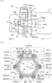
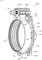
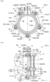
- a pipe retaining device 1A roughly includes: a retaining ring 3 which is tightened and fixed to the outer peripheral surface of a joint pipe 100 by reducing the diameter of a ring body 30A having a C-shaped ring shape by tightening means 9; a pressing ring 4A which presses a packing 6 against a receiving portion 21 of a fitting body 2; connecting means 5 which connects and fixes the retaining ring 3A and the pressing ring 4A to the fitting body 2; and an inclination mechanism 7 which will be described later.
- the joint pipe 100 is, for example, a high-performance polyethylene pipe (also referred to as Higher Performance Polyethylene, commonly known as "HPPE", or “third generation high-density polyethylene pipe”), and the nominal diameter thereof is 150.
- HPPE Higher Performance Polyethylene
- the pipe retaining device 1 improves the holding force (detachment preventing force) for the pipe and also improves workability without hindering the diameter reduction.
- MRS minimum required strength
- the long-term hydrostatic strength is a circumferential stress value that allows the pipe to withstand use at 20° for 50 years, and is calculated (predicted) on the basis of data of an internal pressure creep test.
- a detachment preventing force for the pipe which further exceeds the specified test load specified for each nominal diameter with respect to pipe strength is ensured.
- a pipe detachment preventing force equal to or greater than the pipe strength for a high-performance polyethylene pipe a pipe having a pipe detachment preventing force of 40 kN or more in the case of a nominal diameter of 75, a pipe having a pipe detachment preventing force of 77 kN or more in the case of a nominal diameter of 100, and a pipe having a pipe detachment preventing force of 160 kN or more in the case of a nominal diameter of 150 correspond to type 1, and are classified as pipes for which the joint strength is equal to or higher than the pipe strength.
- the high-performance polyethylene pipe is usually not used as an exposed pipe but is used as a buried pipe. Therefore, the pipe is not bent and deformed by the normal use pressure (0.75 MPa) or the water pressure of a water pressure leak test (0.5 MPa or less) after construction.
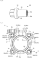
- the fitting body 2 has the receiving portion 21 having a tapered shape, and a cavity 22 for positioning an end portion of the joint pipe 100 therein, and a flange 23 having a substantially rectangular shape is provided on the outer periphery of the fitting body 2.
- a through hole 24 through which a first penetrating member 51, which will be described later, is inserted is formed at each of the four corners of the flange 23.
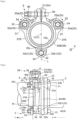
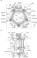
- the retaining ring 3A roughly includes the ring body 30A, a pair of projecting pieces 31, 31 provided at both circumferential end portions 30x, 30x of the ring body 30A, and a plurality of retaining ring connecting portions 32 arranged at appropriate intervals along the circumferential direction of the ring body 30A.
- Each projecting piece 31 has a through hole 31a through which a bolt 9a of the tightening means 9 is caused to extend.
- the retaining ring connecting portions 32 include first retaining ring connecting portions 32a adjacent to the projecting piece 31, and second retaining ring connecting portions 32b which are farther from the projecting piece 31 than the first retaining ring connecting portions 32a are, and are provided in a pair so as to be line-symmetrical with respect to a center line L connecting a central axis C of the retaining ring 3A and a circumferential center portion 30y.
- the first and second retaining ring connecting portions 32a and 32b are provided with elongated holes 33a and 33b as retaining ring penetration portions 33 through which second penetrating members 52. which will be described later, are caused to extend.
- a longitudinal direction D1 of the elongated hole 33a of each first retaining ring connecting portion 32a (a center line d1 of the elongated hole 33a) is oriented toward the projecting piece 31 and intersects the center line L.
- a longitudinal direction D2 of the elongated hole 35b of each second retaining ring connecting portion 32b (a center line d2 of the elongated hole 33b) is parallel to the center line L.
- first and second ribs 37 and 38 are provided on the outer surface of the ring body 30A so as to project outward.
- Each first rib 37 is provided between the first retaining ring connecting portion 32a and the second retaining ring connecting portion 32b, and is formed so as to be gradually thinner (lower) from the first retaining ring connecting portion 32a toward the second retaining ring connecting portion 32b.
- the second rib 38 is provided between a pair of the second retaining ring connecting portions 32b, 32b, and is formed with a uniform wall thickness (height).
- the diameter of the ring body 30A is reduced by the tightening means 9 substantially uniformly in the circumferential direction.
- a plurality of tooth portions 39 which bite into the joint pipe 100 due to the diameter reduction of the ring body 30A by the tightening means 9 are formed on the inner peripheral surface of the ring body 30A along the circumferential direction.
- the pressing ring 4A includes a main body 40 having an annular shape, and first and second pressing ring connecting portions 42a and 42b which protrude outward from the main body 40 and which face the first and second retaining ring connecting portions 32a and 32b in a pipe axis direction X.
- a circular pressing ring through hole 43 through which the first penetrating member 51 is caused to extend is provided at each of the centers of the first and second pressing ring connecting portions 42a and 42b.
- the first and second pressing ring connecting portions 42a and 42b have the same shape, and are provided at equal intervals of approximately 90° so as to be rotationally symmetrical with respect to the center of the pressing ring 4A.
- the longitudinal direction D1 of the elongated hole 33a corresponds to a straight line connecting the positions of the through hole 43 of the first pressing ring connecting portion 42a with respect to the ring body 30A before and after tightening the retaining ring 3A.
- the longitudinal direction D2 of the elongated hole 33b corresponds to a straight line connecting the positions of the through hole 43 of the second pressing ring connecting portion 42b with respect to the ring body 30A before and after tightening the retaining ring 3A.
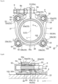
- each connecting means 5 roughly includes the first penetrating member 51 which extends through the through hole 24 of the fitting body 2 and the pressing ring through hole 43, and the second penetrating member 52 which includes: a connection portion 53 extending through the retaining ring penetration portion 33 (elongated hole 33a or 33b) and connected to the first penetrating member 51; and a facing portion 54 facing the retaining ring connecting portion 32 (first or second retaining ring connecting portion 32a or 32b) in the pipe axis direction X.
- the first penetrating member 51 is a T-shaped bolt
- the second penetrating member 52 is a flanged cap nut.
- the connection portion 53 is a cylindrical portion inside of which a thread groove 53a is formed
- the facing portion 54 is a ring-shaped flange portion protruding outward from the cylindrical portion 53.
- each connecting means 5 further includes a washer 55 as a contact member through which the T-shaped bolt 51 extends and which comes into contact with the cylindrical portion 53 and the pressing ring connecting portion 42.
- the pressing ring 4 is fixed to the fitting body 2 by the connecting means 5 before tightening the ring body 30A (reducing the diameter of the retaining ring 4) ( FIG. 5C ).
- the centers of the T-shaped bolt 51 and the pressing ring through hole 43 may be displaced relative to each other.
- the contact area of the flanged cap nut 52 with respect to the pressing ring connecting portion 42 is wider (larger) than that when an end portion 53b of the cylindrical portion 53 is brought into direct contact with the pressing ring connecting portion 42.
- the flanged cap nut 52 is screwed to the T-shaped bolt 51, the surface of the pressing ring connecting portion 42 is not scratched by the rotation of the cylindrical portion 53. Moreover, the washer 55 is merely compressed without rotating together with the flanged cap nut 52. Therefore, even if the flanged cap nut 52 comes into contact with the retaining ring penetration portion 33 when the retaining ring 3A is tightened, the flanged cap nut 52 to which the T-shaped bolt 51 has been screwed slides smoothly due to the washer 55, and does not hinder the diameter reduction of the retaining ring 3A.
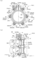
- the inclination mechanism 7A inclines the retaining ring 3A in the pipe axis direction X with respect to a reference plane P orthogonal to the central axis C of the ring body 30A, such that each circumferential end portion 30x of the ring body 30A is caused to be closer to the fitting body 2 and the circumferential center portion 30y is moved away from the fitting body 2.
- the inclination mechanism 7A inclines the retaining ring 3A toward a horizontal plane N which includes the central axis C of the ring body 30A and which is orthogonal to the center line L connecting a center O of the ring body 30A and the circumferential center portion 30y.
- the pipe since the high-performance polyethylene pipe is used as a buried pipe, the pipe is not bent and deformed by the normal use pressure or in a water pressure leak test. That is, the inclination mechanism 7 functions when a large pulling force is generated at the pipe in a normal use state.
- each of first surfaces 56 (facing plane Q shown by an alternate long and short dash line in FIG. 5B ), facing the respective retaining ring connecting portions 32a and 32b, of the flange portions 54 is parallel to the reference plane P.
- second surfaces 34a and 34b, facing the flange portions 54, of the first and second retaining ring connecting portions 32a and 32b are located within the same inclined plane PI inclined in the pipe axis direction X at an inclination angle ⁇ with respect to the reference plane P.
- the inclination mechanism 7A includes the second surfaces 34a and 34b of the retaining ring connecting portions 32 (first and second retaining ring connecting portions 32a and 32b) (inclined plane PI) and the first surfaces 56 of the flange portions (facing portions) 54.
- an interval B between the first surface 56 and the inclined plane PI becomes larger from the circumferential end portions 30x toward the circumferential center portion 30y. It should be noted that in FIG. 5B , each first surface 56 is located within the same facing plane Q.
- the fitting body 2 side of the ring body 30 at the circumferential center portion 30y tries to bite into the joint pipe 100 due to the inclination of the retaining ring 3, and thus the amount by which the tooth portions 39 at the circumferential center portion 30y bite is decreased (the teeth are raised). Then, when the pipe pulling force F further acts, the joint pipe 100 is displaced relative to the retaining ring 3A on the circumferential center portion 30y side. Therefore, the effect of improving the detachment preventing force for the pipe due to the inclination of the retaining ring 3 is small as compared to the present embodiment.
- the inclination mechanism 7 of the present invention causes each circumferential end portion 30x of the ring body 30A to be closer to the fitting body 2 and also moves the circumferential center portion 30y away from the fitting body 2.
- the inclined plane PI is inclined at an inclination angle ⁇ that is greater than 0° and not greater than 5° with respect to the reference plane P.
- the inclination angle 0 is not less than 1° and not greater than 5°.
- the inclination angle is not less than 2° and not greater than 3°.
- the maximum load was 171.9 kN in the case of an inclination angle of 0°.
- the maximum load was 177.2 kN at an inclination angle of 2°, and the maximum load was 184.4 kN at an inclination angle of 3°.
- the maximum load was 171.8 kN.
- a pipe that is classified as type 1 in the UK water industry standard is a pipe that has a pipe detachment preventing force of 160 kN or more with a nominal diameter of 150.
- 171.8 - 160 11.8 kN.
- 184.4 - 160 24.4 kN.
- FIGS. 1 to 3 show the pipe retaining device 1A in which an opening nut 9c is mounted on the pair of projecting pieces 31, 31.
- This state is a state before tightening the retaining ring 3A (before diameter reduction) and before firmly tightening the connecting means 5 (before completion of screwing with the thread groove 53a).
- the fitting body 2 and the pressing ring 4A are not in contact with each other, and the packing 6 does not become deformed.
- the tooth portions 39 of the retaining ring 3A do not bite into the joint pipe 100.
- each flanged cap nut 52 is firmly tightened (finally tightened) to the T-shaped bolt 51 to connect the retaining ring 3A and the pressing ring 4A to the fitting body 2 (screwing with the thread groove 53a is completed).
- the end portion 53b of each cylindrical portion 53 comes into contact with the washer 55, and the pressing ring 4A presses the packing 6 against the receiving portion 21 to compress and deform the packing 6 and also comes into contact with the fitting body 2.
- the retaining ring 3A has not been tightened yet.
- a maximum width (length) W1 in the pipe axis direction of each retaining ring connecting portion 32 is shorter than a length W2 of the cylindrical portion 55 (distance from the flange portion 54 to the cylindrical portion end portion 53b).
- a gap S is formed between the flange portions 54 and the first and second pressing ring connecting portions 42a and 42b at the first and second retaining ring connecting portions 32a and 32b. Therefore, it is not necessary to manually tighten (temporarily tighten) the connecting means 5 to temporarily fix the pipe before tightening and fixing the tightening means 9 of the retaining ring 3A as in the conventional art, and it is sufficient that the pressing ring 4A is merely firmly tightened (finally tightened), so that the work is simple, and the workability is good.
- the tightening means 9 of the retaining ring 3A is tightened to reduce the diameter of the ring body 30A. Since the outer diameters of the cylindrical portions 53 are smaller than the diameters (widths) in the lateral direction of the elongated holes 33a and 33b, the flanged cap nuts 52 move relative to the ring body 30A along the longitudinal directions D1 and D2 within the elongated holes 33a and 33b.
- the diameter reduction of the ring body 30A is guided along the oriented directions (longitudinal directions D1 and D2) of the elongated holes 33a and 33b, and the first and second retaining ring connecting portions 32a and 32b move so as to follow the diameter reduction of the ring body 30A.
- the central axes of the respective connecting means 5 having moved from one ends to the other ends of the elongated holes 33a and 33b coincide with the centers of the respective through holes 43 of the pressing ring connecting portions 42a and 42b.
- the center of the retaining ring 3A reduced in diameter by tightening and the center of the pressing ring 4A also coincide with each other. Therefore, the connecting means 5 does not hinder the diameter reduction, and a load is not locally applied to the ring body 30A to cause cracks or the like.
- the retaining ring connecting portions 32 and the pressing ring connecting portions 42 do not come into contact with each other when the diameter of the ring body 30A is reduced, so that no frictional resistance due to contact is generated. Therefore, the diameter reduction can be performed smoothly with low torque, so that the workability is good. Furthermore, since the retaining ring 3A is not fixed to the fitting body 2, and the first and second retaining ring connecting portions 32a and 32b and the flange portions 54 are separated from each other, the joint pipe 100 can be stretched and contracted.
- the space (interval B) formed at the first surface 56 of the flange portion 54 of the flanged cap nut 52 is larger at the second surface 34b of each second retaining ring connecting portion 32b than at the second surface 34a of each first retaining ring connecting portion 32a, and is larger at the lower portion (circumferential center portion 30y) than at the upper portion (circumferential end portion 30x side).
- a space (gap) is formed such that the interval B therebetween becomes larger from the circumferential end portions 30x toward the circumferential center portion 30y.
- the retaining ring 4A is inclined with the upper ends 56a as a base such that each circumferential end portion 30x is caused to be closer to the fitting body 2 and the circumferential center portion 30y is moved away from the fitting body 2. Then, the ring body 30A comes into contact with the joint pipe 100 to deform (bend) the joint pipe 100. A formed deformed portion M opposes the pipe pulling force F, so that it is possible to greatly improve the detachment preventing force for the pipe.
- the biting of the tooth portions 39 of the retaining ring 3A is shallow in the vicinity of the circumferential center portion 30y.
- the retaining ring 3A can be relatively easily inclined to form the deformed portion M in the joint pipe 100, so that the detachment preventing force for the pipe can be further improved.
- the tooth portions 39 at the circumferential center portion 30y further bite into the joint pipe 100, so that the pipe detachment preventing force is further improved.
- the second surfaces 34a and 34b of the retaining ring connecting portion 32 are formed as flat surfaces and forming the first surfaces 56 of the flange portions 54 as inclined surfaces, it is also conceivable to incline the retaining ring 3A in the same manner as described above to deform the joint pipe 100.
- FIGS. 8 to 12 a second embodiment of the present invention will be described with reference to FIGS. 8 to 12 . It should be noted that the same members as those of the above-described embodiment are designated by the same reference characters.
- connection to the fitting body 2 is made by the connecting means 5 at the retaining ring connecting portions 32 (first and second retaining ring connecting portions 32a and 32b) at the four locations.
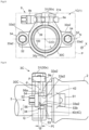
- the retaining ring connecting portions 32 of a retaining ring 3B according to the second embodiment include a pair of first retaining ring connecting portions 32a, 32a and one second retaining ring connecting portion 32b1 at three locations.
- the nominal diameter of the joint pipe 100 is, for example, 100.
- the second retaining ring connecting portion 32b1 is located at the circumferential center portion 30y of a ring body 30B, and a recess 33b1 is formed therein as a second retaining ring penetration portion so as to be open on one side thereof.
- the recess 33b1 has a smaller width than the flange portion 54 and extends along the center line L.
- the second surfaces 34a and 34b, facing the flange portions 54, of the first and second retaining ring connecting portions 32a and 32b1 are located within the same inclined plane PI inclined in the pipe axis direction X at an inclination angle ⁇ with respect to the reference plane P.
- the inclined plane PI is inclined at an inclination angle ⁇ that is greater than 0° and not greater than 5° with respect to the reference plane P.
- the inclination angle ⁇ is not less than 1° and not greater than 5°.
- the space (interval B) formed at the first surface 56 of the flange portion 54 of the flanged cap nut 52 is larger at the second surface 34b of the second retaining ring connecting portion 32b1 than at the second surface 34a of each first retaining ring connecting portion 32a, and is larger at the lower portion (circumferential center portion 30y) than at the upper portion (circumferential end portion 30x side).
- the tightening means 9 of the retaining ring 3B can be tightened to reduce the diameter of the ring body 30B.
- the flanged cap nuts 52 slide along the longitudinal direction D1 within the elongated holes 33a.
- the connecting means 5 does not hinder the diameter reduction and does not come off from the recess 33bl.
- an elongated hole may be formed along the center line L.
- the retaining ring 4B is inclined with the upper ends 56a as a base due to the interval B (space) and the inclined plane PI (second surfaces 34a and 34b) shown in FIG. 9 . Then, the ring body 30B comes into contact with the joint pipe 100 to deform (bend) the joint pipe 100. A formed deformed portion M opposes the pipe pulling force F, and the tooth portions 39 at the circumferential center portion 30y further bite into the joint pipe 100, so that it is possible to greatly improve the detachment preventing force for the pipe.
- the retaining ring connecting portions 32 of a retaining ring 3C include only a pair of first retaining ring connecting portions 32a2 and 32a2 at two locations. It should be noted that in the present embodiment, the nominal diameter of the joint pipe 100 is, for example, 50 or 75.
- the pair of first retaining ring connecting portions 32a2 and 32a2 are each located at an intermediate portion between the circumferential center portion 30y and the circumferential end portion 30x of a ring body 30C, and are arranged so as to be line-symmetrical with respect to the center line L.
- a recess 33a2 is formed as a first retaining ring penetration portion in each first retaining ring connecting portion 32a2 so as to be open on the outer side thereof.
- the recess 33a2 has a smaller width than the flange portion 54.
- the second surfaces 34, facing the flange portions 54, of the first retaining ring connecting portions 32a2 are located within the same inclined plane PI inclined in the pipe axis direction X at an inclination angle ⁇ with respect to the reference plane P.
- the inclined plane PI is inclined at an inclination angle ⁇ that is greater than 0° and not greater than 10° with respect to the reference plane P.
- the inclination angle ⁇ is not less than 1° and not greater than 6°.
- the space (interval B) formed between the first surface 56 of the flange portion 54 of the flanged cap nut 52 and the second surface 34 of the first retaining ring connecting portion 32a2 is larger at the lower portion (circumferential center portion 30y) than at the upper portion (circumferential end portion 30x side).
- the tightening means 9 of the retaining ring 3C can be tightened to reduce the diameter of the ring body 30C.
- the flanged cap nuts 52 slide along the center line L within the recesses 33a2. Therefore, the connecting means 5 does not hinder the diameter reduction and does not come off from each recess 33a2. Instead of the recess 33a2 which is open on the outer side thereof, an elongated hole may be formed along the center line L.
- the opening width of the recess 33a2 and the width of the inner portion of the recess 33a2 are equal to each other, but the recess 33a2 may be formed such that the opening width is smaller than the width of the inner portion (the shape of the recess is substantially a C-shape as viewed in the pipe axis direction).
- the shape of the recess 33a2 is not limited to the shape in the present embodiment as long as the shape is a shape that allows the flanged cap nut 52 to slide within the recess 33a2.
- the retaining ring 4C is inclined with the upper ends 56a as a base due to the interval B (space) and the inclined plane PI (second surfaces 34a) shown in FIG. 14 . Then, the ring body 30C comes into contact with the joint pipe 100 to deform (bend) the joint pipe 100. A formed deformed portion M opposes the pipe pulling force F, and the tooth portions 39 at the circumferential center portion 30y further bite into the joint pipe 100, so that it is possible to greatly improve the detachment preventing force for the pipe.
- the retaining ring connecting portions 32 of a retaining ring 3D include a pair of first retaining ring connecting portions 32a, 32a, a pair of second retaining ring connecting portions 32b2, 32b2, and a pair of third retaining ring connecting portions 32c, 32c at six locations, and the respective connecting portions are arranged in pairs so as to be line-symmetrical with respect to the center line L.
- the nominal diameter of the joint pipe 100 is, for example, 250.
- each second retaining ring connecting portion 32b2 is located in the vicinity of the circumferential center portion 30y of a ring body 30D.
- each third retaining ring connecting portion 32c is provided at the center between the first retaining ring connecting portion 32a and the second retaining ring connecting portion 32b2 (position shifted by 90° in the circumferential direction of the ring body 30 from the circumferential center portion 30y of the ring body 30C).
- the second retaining ring connecting portions 32b2 and the third retaining ring connecting portions 32c are provided with elongated holes 33b2 and 33c having a smaller width than the flange portion 54.
- the first retaining ring connecting portions 32a have the same configuration as in the above first embodiment.
- the longitudinal direction D1 (center line d1) of the elongated hole 33a of each first retaining ring connecting portion 32a and a longitudinal direction D3 (center line d3) of the elongated hole 33c of each third retaining ring connecting portion 32c are oriented toward the projecting piece 31 and intersect the center line L.
- an intersection angle ⁇ 1 of the center line d1 with respect to the center line L is larger than the intersection angle of the center line d3 with respect to the center line L.
- the longitudinal direction D2 (center line d2) of the elongated hole 33b2 of each second retaining ring connecting portion 32b2 is oriented toward the third retaining ring connecting portion 32c, and the oriented direction thereof is opposite to those of the above center lines d1 and d3.
- the center line d2 is substantially parallel to the center line L, and thus the intersection angle thereof with respect to the center line L is very small as compared to the intersection angle of the center line d3 with respect to the center line L.
- the second surfaces 34a, 34b. and 34c, facing the flange portions 54, of the respective retaining ring connecting portions 32a, 32b2, and 32c are located within the same inclined plane PI inclined in the pipe axis direction X at an inclination angle ⁇ with respect to the reference plane P.
- the inclined plane PI is inclined at an inclination angle ⁇ that is greater than 0° and not greater than 5° with respect to the reference plane P.
- the inclination angle ⁇ is not less than 1° and not greater than 4°.
- the space (interval B) formed between each retaining ring connecting portion (inclined plane PI) and the first surface 56 of the flange portion 54 is larger in the order of the second surface 34a of each first retaining ring connecting portion 32a, the second surface 34c of each third retaining ring connecting portion 32c, and the second surface 34b of each second retaining ring connecting portion 32b2. and is larger at the lower portion (circumferential center portion 30y) than at the upper portion (circumferential end portion 30x side).
- the tightening means 9 of the retaining ring 4D can be tightened to reduce the diameter of the ring body 30D.
- the central axes of the connecting means 5 located at one ends of the elongated holes 33a, 33b2, and 33c of the retaining ring 3D coincide with the centers of the respective through holes of the pressing ring connecting portions 42a, 42b, and 42c.
- the center of the retaining ring 3D and the center of the pressing ring 4D also coincide with each other.
- the flanged cap nuts 52 slide along the respective longitudinal directions D1 to D3 within the elongated holes 33a, 33b2, and 33c.
- the diameter reduction of the ring body 30D is guided along the oriented directions (longitudinal directions D1, D2, and D3) of the elongated holes 33a, 33b2, and 33c, and the respective retaining ring connecting portions 32a, 32b2, and 33c move so as to follow the diameter reduction of the ring body 30D.
- the central axes of the respective connecting means 5 having moved from one ends to the other ends of the elongated holes 33a, 33b2, and 33c coincide with the centers of the respective through holes of the pressing ring connecting portions 42a, 42b, and 42c.
- the center of the retaining ring 3D reduced in diameter by tightening and the center of the pressing ring 4D also coincide with each other. Therefore, the connecting means 5 does not hinder the diameter reduction, and a load is not locally applied to the ring body 30D to cause cracks or the like.
- the retaining ring 3D is inclined with the upper ends 56a as a base due to the interval B (space) and the inclined plane PI (second surfaces 34a, 34b, and 34c). Then, the ring body 30D comes into contact with the joint pipe 100 to deform (bend) the joint pipe 100. A formed deformed portion M opposes the pipe pulling force F, and the tooth portions 39 at the circumferential center portion 30y further bite into the joint pipe 100, so that it is possible to greatly improve the detachment preventing force for the pipe.
- the retaining ring connecting portions 32 of a retaining ring 3E include a pair of first retaining ring connecting portions 32a, 32a, a second retaining ring connecting portion 32b3 located at the circumferential center portion 30y of a ring body 30E, and a pair of third retaining ring connecting portions 32c1, 32c1 at five locations, and the respective connecting portions are arranged in pairs so as to be line-symmetrical with respect to the center line L.
- the nominal diameter of the joint pipe 100 is, for example, 250 or 300.
- each third retaining ring connecting portion 32c1 is provided at the middle (center) between the first retaining ring connecting portion 32a and the second retaining ring connecting portion 32b3.
- the second retaining ring connecting portion 32b3 and the third retaining ring connecting portions 32c1 are provided with elongated holes 33b3 and 33c1 having a smaller width than the flange portion 54.
- the first retaining ring connecting portions 32a have the same configuration as in the above second embodiment.
- the longitudinal direction D1 (center line d1) of the elongated hole 33a of each first retaining ring connecting portion 32a and a longitudinal direction D3 (center line d3) of the elongated hole 33c1 of each third retaining ring connecting portion 32cl are oriented toward the projecting piece 31 and intersect the center line L.
- an intersection angle ⁇ 1 of the center line d1 with respect to the center line L is larger than the intersection angle of the center line d3 with respect to the center line L.
- the longitudinal direction D2 (center line d2) of the elongated hole 33bb of the second retaining ring connecting portion 32b3 coincides with the center line L.
- the second surfaces 34a, 34b, and 34c, facing the flange portions 54, of the respective retaining ring connecting portions 32a, 32b3, and 32c1 are located within the same inclined plane PI inclined in the pipe axis direction X at an inclination angle ⁇ with respect to the reference plane P.
- the inclined plane PI is inclined at an inclination angle ⁇ that is greater than 0° and not greater than 5° with respect to the reference plane P.
- the inclination angle ⁇ is not less than 1° and not greater than 4°.
- the space (interval B) formed between each retaining ring connecting portion (inclined plane PI) and the first surface 56 of the flange portion 54 is larger in the order of the second surface 34a of each first retaining ring connecting portion 32a, the second surface 34c of each third retaining ring connecting portion 32c, and the second surface 34b of the second retaining ring connecting portion 32b3, and is larger at the lower portion (circumferential center portion 30y) than at the upper portion (circumferential end portion 30x side).
- the tightening means 9 of the retaining ring 3E can be tightened to reduce the diameter of the ring body 30E.
- the central axes of the connecting means 5 located at one ends of the elongated holes 33a, 33b3, and 33c1 of the retaining ring 3E coincide with the centers of the respective through holes of the pressing ring connecting portions 42a, 42b, and 42c.
- the center of the retaining ring 3E and the center of the pressing ring 4E also coincide with each other.
- the flanged cap nuts 52 slide along the respective longitudinal directions D1 to D3 within the elongated holes 33a, 33b3, and 33c1.
- the diameter reduction of the ring body 30E is guided along the oriented directions (longitudinal directions D1, D2, and D3) of the elongated holes 33a, 33b3, and 33c1, and the respective retaining ring connecting portions 32a, 32b3, and 33c1 move so as to follow the diameter reduction of the ring body 30E.
- the central axes of the respective connecting means 5 having moved from one ends to the other ends of the elongated holes 33a, 33b3, and 33c1 coincide with the centers of the respective through holes of the pressing ring connecting portions 42a, 42b, and 42c.
- the center of the retaining ring 3E reduced in diameter by tightening and the center of the pressing ring 4E also coincide with each other. Therefore, the connecting means 5 does not hinder the diameter reduction, and a load is not locally applied to the ring body 30E to cause cracks or the like.
- the retaining ring 4D is inclined with the upper ends 56a as a base due to the interval B (space) and the inclined plane PI (second surfaces 34a, 34b, and 34c). Then, the ring body 30D comes into contact with the joint pipe 100 to deform (bend) the joint pipe 100. A formed deformed portion M opposes the pipe pulling force F, and the tooth portions 39 at the circumferential center portion 30y further bite into the joint pipe 100, so that it is possible to greatly improve the detachment preventing force for the pipe.
- High-performance polyethylene pipes include SDR13.6, SDR17, and SDR21 in addition to SDR11, depending on the relationship between pipe outer diameter and wall thickness, and the present invention can also be applied to these high-performance polyethylene pipes.
- the present invention can also be applied to crosslinked polyethylene pipes and polybuden pipes used as hot water pipes, etc.
- the third retaining ring connecting portions 33c are provided between the first retaining ring connecting portions 32a and the second retaining ring connecting portions 32b, and these connection portions are provided so as to be line-symmetrical with respect to the center line L.
- the present invention is not limited thereto, and a plurality of pairs of third retaining ring connecting portions 33c may be provided.
- a joint pipe having a larger bore diameter can be handled by using, for example, 8 or 10 first penetrating members (T-shaped bolts) 51 and 8 or 10 second penetrating members (flanged cap nuts) 52 such that these members are line-symmetrical with respect to the center line L.
- first retaining ring connecting portions 32a, 32a and one second retaining ring connecting portion 32b1 are provided.
- the present invention is not limited thereto, and a plurality of pairs of first retaining ring connecting portions 32c may be provided.
- a joint pipe having a larger bore diameter can be handled by using, for example, 5 or 7 first penetrating members (T-shaped bolts) 51 and 5 or 7 second penetrating members (flanged cap nuts) 52 such that these members are line-symmetrical with respect to the center line L.
- an inner core is omitted, but the present invention can also be applied to the case of using an inner core.
- the inner core prevents the diameter of the joint pipe 100 from being reduced, but according to an experiment by the inventor, it was confirmed that when the pipe pulling force is increased, the retaining ring 4 is inclined by the inclination mechanism 7 and the joint pipe 100 and the fitting body 2 are maintained coaxially. That is, the present invention can be used (shared) regardless of whether or not the inner core is used, and the versatility is extremely high.
Landscapes
- Engineering & Computer Science (AREA)
- General Engineering & Computer Science (AREA)
- Mechanical Engineering (AREA)
- Joints With Sleeves (AREA)
- Quick-Acting Or Multi-Walled Pipe Joints (AREA)
Claims (9)
- Rohrhalterungsvorrichtung (1) für eine Rohrverbindung, umfassend:einen Sicherungs- bzw. Haltering (3), der einen Ringkörper (30) mit einer C-förmigen Ringform umfasst,Abdichtungsmittel (9),einen Druckring (4),eine Dichtung (6),Verbindungsmittel (5), undeinen Anbringungskörper (2), der einen Aufnahmeteilbereich (21) umfasst,wobeider Sicherungsring (3) durch Reduzieren eines Durchmessers des Ringkörpers (30) mit der C-förmigen Ringform durch die Abdichtungsmittel (9) an einer äußeren Umfangsfläche eines Verbindungsrohrs (100) enger gemacht und fixiert werden kann; wobei der Druckring (4) konfiguriert ist, um die Dichtung (6) gegen den Aufnahmeteilbereich (21) des Anbringungskörper (2) zu drücken; und die Verbindungsmittel (5) konfiguriert sind, um den Sicherungsring (3) und den Druckring (4) mit dem Anbringungskörper (2) zu verbinden, wobeider Sicherungsring (3) ein Paar von vorstehenden Teilen (31) enthält, die an beiden umlaufenden Endteilbereichen (30x) des Ringkörpers (30) vorgesehen sind, und jeder von ihnen ein Durchgangsloch (31a) hat, durch das die Abdichtungsmittel (9) sich zu erstrecken veranlasst werden, einen Zahnteilbereich (39), der auf einer Innenseite des Ringkörpers (30) vorgesehen ist und der zum Einschneiden in das Verbindungsrohr (100) aufgrund einer Durchmesserreduktion durch die Abdichtungsmittel (9) dient, und eine Vielzahl von Sicherungsring-Verbindungsteilbereichen (32), die in geeigneten Intervallen entlang einer Umfangsrichtung des Ringkörpers (30) angeordnet sind und von welchen jeder einen Sicherungsring-Durchdringungsteilbereich (33) hat, durch den die Verbindungsmittel (5) sich zu erstrecken veranlasst werden,der Druckring (4) eine Vielzahl von Druckring-Verbindungsteilbereichen (42) enthält, die der Vielzahl von Sicherungsring-Verbindungsteilbereichen (32) in einer Rohrachsenrichtung (X) gegenüberliegen und von welchen jeder ein Druckring-Durchgangsloch (43) hat, durch das die Verbindungsmittel (5) sich zu erstrecken veranlasst werden,die Verbindungsmittel (5) erste Durchdringungselemente (51) enthalten, von welchen sich jedes durch ein Durchgangsloch (24) des Anbringungskörpers (2) und das Druckring-Durchgangsloch (43) erstreckt, und zweite Durchdringungselemente (52), von welchen jedes einen Verbindungsteilbereich (53) enthält, der sich durch den Sicherungsring-Durchdringungsteilbereich (33) erstreckt und verbunden ist mit dem ersten Durchdringungselement (51) und einem gegenüberliegenden Teilbereich (54), der dem Sicherungsring-Verbindungsteilbereich (32) in der Rohrachsenrichtung (X) gegenüberliegt,dadurch gekennzeichnet, dassdie Rohrhalterungsvorrichtung (1) einen Neigungsmechanismus (7) enthält, der konfiguriert ist, um den Sicherungsring (3) in der Rohrachsenrichtung (X) in Bezug auf eine Referenzebene (P) orthogonal zu einer zentralen Achse (C) des Ringkörpers (30) zu neigen, so dass veranlasst wird, dass jeder umlaufende Endteilbereich (30x) des Ringkörpers (30) näher zum Anbringungskörper (2) ist und ein umlaufender zentraler Teilbereich (30y) des Ringkörpers (30) vom Anbringungskörper (2) wegbewegt wird, wenn jeder Sicherungsring-Verbindungsteilbereich (32) und jeder gegenüberliegende Teilbereich (54) in einem Zustand in Kontakt miteinander gelangen, in welchem der Durchmesser des Ringkörpers (30) durch die Abdichtungsmittel (9) reduziert ist,eine erste Oberfläche (56), die dem Sicherungsring-Verbindungsteilbereich (32) gegenüberliegt, von jedem gegenüberliegenden Teilbereich (54) parallel zu Referenzebene (P) ist,zweite Oberflächen (34), die den gegenüberliegenden Teilbereichen (54) gegenüberliegen, der Vielzahl von Sicherungsring-Verbindungsteilbereichen (32) innerhalb derselben geneigten Ebene (PI) angeordnet sind, die in der Rohrachsenrichtung (X) in Bezug auf die Referenzebene (P) geneigt ist, undein Intervall (B) zwischen der ersten Oberfläche (56) und der geneigten Ebene (PI) von den umlaufenden Endteilbereichen (30x) in Richtung zu dem umlaufenden zentralen Teilbereich (30y) größer wird.
- Rohrhalterungsvorrichtung für eine Rohrverbindung nach Anspruch 1, wobeidie Vielzahl von Sicherungsring-Verbindungsteilbereichen (32) ein Paar von ersten Sicherungsring-Verbindungsteilbereichen (32a) benachbart zu dem Paar von vorstehenden Teilen (31) und ein Paar von zweiten Sicherungsring-Verbindungsteilbereichen (32b) benachbart zu dem Paar von ersten Sicherungsring-Verbindungsteilbereichen (32a) enthält,das Paar von ersten Sicherungsring-Verbindungsteilbereichen (32a) und das Paar von zweiten Sicherungsring-Verbindungsteilbereichen (32b) angeordnet sind, um liniensymmetrisch in Bezug auf eine Mittenlinie (L) zu sein, die die zentrale Achse (C) und den umlaufenden zentralen Teilbereich (30y) verbindet,erste Sicherungsring-Durchdringungsteilbereiche (33a) der ersten Sicherungsring-Verbindungsteilbereiche (32a) jeweils ein längliches Loch sind, in dem der Verbindungsteilbereich (53) entlang der Umfangsrichtung des Ringkörpers (30) verschiebbar ist und das eine kleinere Breite als der gegenüberliegende Teilbereich (54) hat, undzweite Sicherungsring-Durchdringungsteilbereiche (33b) der zweiten Sicherungsring-Verbindungsteilbereiche (32b) jeweils ein längliches Loch sind, in dem der Verbindungsteilbereich (53) in einer Richtung entlang der Mittenlinie (L) verschiebbar ist und das eine kleinere Breite als der gegenüberliegende Teilbereich (54) hat.
- Rohrhalterungsvorrichtung (1) für eine Rohrverbindung nach Anspruch 1, wobeidie Vielzahl von Sicherungsring-Verbindungsteilbereichen (32) ein Paar von ersten Sicherungsring-Verbindungsteilbereichen (32a2) benachbart zu dem Paar von vorstehenden Teilen (31) und einen zweiten Sicherungsring-Verbindungsteilbereich (32b2), der bei dem umlaufenden zentralen Teilbereich (30y) lokalisiert ist, enthält,das Paar von ersten Sicherungsring-Verbindungsteilbereichen (32a2) angeordnet ist, um liniensymmetrisch in Bezug auf einen Mittenlinie (L) zu sein, die die zentrale Achse (X) und den umlaufenden zentralen Teilbereich (30y) verbindet,erste Sicherungsring-Durchdringungsteilbereiche (33a2) der erste Sicherungsring-Verbindungsteilbereiche (32a2) jeweils ein längliches Loch sind, in dem der Verbindungsteilbereich (53) entlang der Umfangsrichtung des Ringkörpers (30) verschiebbar ist und das eine kleinere Breite als der gegenüberliegende Teilbereich (54) hat, undein zweiter Sicherungsring-Durchdringungsteilbereich (33b2) des zweiten Sicherungsring-Verbindungsteilbereichs (32b2) ein Ausschnitt ist, der auf einer Seite davon offen ist, oder ein Loch, das eine kleinere Breite als der gegenüberliegende Teilbereich (54) hat und in dem der Verbindungsteilbereich (53) in einer Richtung entlang der Mittenlinie (L) verschiebbar ist.
- Rohrhalterungsvorrichtung (1) für eine Rohrverbindung nach Anspruch 1, wobeidie Vielzahl von Sicherungsring-Verbindungsteilbereichen (32) ein Paar von Sicherungsring-Verbindungsteilbereichen enthält, die jeweils bei einem mittleren bzw. zwischenliegenden Teilbereich zwischen dem umlaufenden zentralen Teilbereich (30y) und dem umlaufenden Endteilbereich (30x) des Ringkörpers (30) lokalisiert sind,das Paar von Sicherungsring-Verbindungsteilbereichen (32) angeordnet ist, um liniensymmetrisch in Bezug auf eine Mittenlinie (L) zu sein, die die zentrale Achse (C) und den umlaufenden zentralen Teilbereich (30y) verbindet, undSicherungsring-Durchdringungsteilbereiche (33) der Sicherungsring-Verbindungsteilbereiche (32) jeweils ein Ausschnitt sind, der auf einer Seite davon offen ist, oder ein längliches Loch, das eine kleinere Breite als der gegenüberliegende Teilbereich (54) hat und in dem der Verbindungsteilbereich (53) verschiebbar ist.
- Rohrhalterungsvorrichtung (1) für eine Rohrverbindung nach Anspruch 1, wobeidie Vielzahl von Sicherungsring-Verbindungsteilbereichen (32) ein Paar von ersten Sicherungsring-Verbindungsteilbereichen (32a) benachbart zu dem Paar von vorstehenden Teilen (31), ein Paar von zweiten Sicherungsring-Verbindungsteilbereichen (32b) benachbart zu dem umlaufenden zentralen Teilbereich (30y) und ein Paar von dritten Sicherungsring-Verbindungsteilbereichen (32c), die jeweils bei einem mittleren bzw. zwischenliegenden Teilbereich zwischen dem ersten Sicherungsring-Verbindungsteilbereich (32a) und dem zweiten Sicherungsring-Verbindungsteilbereich (32b) lokalisiert sind, enthält,das Paar von ersten Sicherungsring-Verbindungsteilbereichen (32a), das Paar von zweiten Sicherungsring-Verbindungsteilbereichen (32b) und das Paar von dritten Sicherungsring-Verbindungsteilbereichen (32c) angeordnet sind, um liniensymmetrisch in Bezug auf eine Mittenlinie (L) zu sein, die die zentrale Achse (C) und den umlaufenden zentralen Teilbereich (30y) verbindet, undein Sicherungsring-Durchdringungsteilbereich (33) von jedem der Sicherungsring-Verbindungsteilbereiche (32) ein längliches Loch ist, in dem der Verbindungsteilbereich (53) entlang der Umfangsrichtung des Ringkörpers (30) verschiebbar ist und das eine kleinere Breite als der gegenüberliegende Teilbereich (54) hat.
- Rohrhalterungsvorrichtung (1) für eine Rohrverbindung nach Anspruch 3, wobeidie Vielzahl von Sicherungsring-Verbindungsteilbereichen (32) weiterhin ein Paar von dritten Sicherungsring-Verbindungsteilbereichen (32c) enthält, die jeweils bei einem mittleren bzw. zwischenliegenden Teilbereich zwischen dem ersten Sicherungsring-Verbindungsteilbereich (32a) und dem zweiten Sicherungsring-Verbindungsteilbereich (32b) lokalisiert sind,das Paar von dritten Sicherungsring-Verbindungsteilbereichen (32c) angeordnet ist, um liniensymmetrisch in Bezug auf die Mittenlinie (L) zu sein, die die zentrale Achse (C) und den umlaufenden zentralen Teilbereich (30y) verbindet, unddritte Sicherungsring-Durchdringungsteilbereiche (33C) der dritten Sicherungsring-Verbindungsteilbereiche (32c) jeweils ein längliches Loch sind, in dem der Verbindungsteilbereich (53) entlang der Umfangsrichtung des Ringkörpers (30) verschiebbar ist und das eine kleinere Breite als der gegenüberliegende Teilbereich (54) hat.
- Rohrhalterungsvorrichtung (1) für eine Rohrverbindung nach einem der Ansprüche 1 bis 6, wobei die ersten Durchdringungselemente (51) T-förmige Bolzen sind und die zweiten Durchdringungselemente (52) angeflanschte Überwurfmuttern sind.
- Rohrhalterungsvorrichtung (1) für eine Rohrverbindung nach Anspruch 7, wobei die Verbindungsmittel (5) weiterhin Kontaktelemente (55) enthalten, wobei sich durch jedes von ihnen das erste Durchdringungselement (51) erstreckt und jedes von ihnen mit dem Verbindungsteilbereich (53) und dem Druckring-Verbindungsteilbereich (42) in Kontakt gelangt.
- Rohrhalterungsvorrichtung (1) für eine Rohrverbindung nach einem der Ansprüche 1 bis 6, wobei die geneigte Ebene (PI) ein Ebene ist, die unter einem Winkel (θ), der größer als 0° und gleich oder kleiner als 5° ist, in der Rohrachsenrichtung (X) in Bezug auf die Referenzebene geneigt ist.
Applications Claiming Priority (2)
| Application Number | Priority Date | Filing Date | Title |
|---|---|---|---|
| JP2019202724 | 2019-11-07 | ||
| PCT/JP2020/041610 WO2021090939A1 (ja) | 2019-11-07 | 2020-11-06 | 管継手の管抜止装置 |
Publications (3)
| Publication Number | Publication Date |
|---|---|
| EP3971460A1 EP3971460A1 (de) | 2022-03-23 |
| EP3971460A4 EP3971460A4 (de) | 2022-08-31 |
| EP3971460B1 true EP3971460B1 (de) | 2023-06-28 |
Family
ID=75848128
Family Applications (1)
| Application Number | Title | Priority Date | Filing Date |
|---|---|---|---|
| EP20884430.8A Active EP3971460B1 (de) | 2019-11-07 | 2020-11-06 | Rohrhaltevorrichtung für rohrverbindung |
Country Status (6)
| Country | Link |
|---|---|
| US (1) | US11499655B2 (de) |
| EP (1) | EP3971460B1 (de) |
| JP (1) | JP6895702B1 (de) |
| CA (1) | CA3177359C (de) |
| DK (1) | DK3971460T3 (de) |
| WO (1) | WO2021090939A1 (de) |
Family Cites Families (4)
| Publication number | Priority date | Publication date | Assignee | Title |
|---|---|---|---|---|
| JP5972482B2 (ja) * | 2013-12-10 | 2016-08-17 | 株式会社川西水道機器 | 管継手の管抜止装置及びその施工方法 |
| JP5918293B2 (ja) | 2014-03-28 | 2016-05-18 | 株式会社川西水道機器 | プラスチック管の離脱防止リング及びプラスチック管の管継手 |
| JP6348897B2 (ja) * | 2015-12-17 | 2018-06-27 | 株式会社川西水道機器 | 管継手の管抜止装置 |
| JP2018109417A (ja) | 2016-12-28 | 2018-07-12 | 株式会社川西水道機器 | 管継手及び複層管の連結構造 |
-
2020
- 2020-11-06 DK DK20884430.8T patent/DK3971460T3/da active
- 2020-11-06 EP EP20884430.8A patent/EP3971460B1/de active Active
- 2020-11-06 CA CA3177359A patent/CA3177359C/en active Active
- 2020-11-06 JP JP2021506351A patent/JP6895702B1/ja active Active
- 2020-11-06 WO PCT/JP2020/041610 patent/WO2021090939A1/ja not_active Ceased
- 2020-11-06 US US17/619,166 patent/US11499655B2/en active Active
Also Published As
| Publication number | Publication date |
|---|---|
| JPWO2021090939A1 (ja) | 2021-11-25 |
| US11499655B2 (en) | 2022-11-15 |
| CA3177359A1 (en) | 2021-05-14 |
| JP6895702B1 (ja) | 2021-06-30 |
| DK3971460T3 (da) | 2023-09-18 |
| EP3971460A4 (de) | 2022-08-31 |
| WO2021090939A1 (ja) | 2021-05-14 |
| CA3177359C (en) | 2023-07-18 |
| EP3971460A1 (de) | 2022-03-23 |
| US20220213990A1 (en) | 2022-07-07 |
Similar Documents
| Publication | Publication Date | Title |
|---|---|---|
| US11174972B2 (en) | Pipe joint | |
| US9746118B2 (en) | Method and structure for preventing slipping-off of a tube in a pipe joint made of fluororesin | |
| WO2012105525A1 (ja) | チューブ継手 | |
| US9879805B2 (en) | Pipe coupling device and construction method therefor | |
| KR102815097B1 (ko) | 분해 방지 연결 부재 및 분해 방지 연결 어셈블리 | |
| WO2015156198A1 (ja) | 管継手 | |
| JP2001124258A (ja) | 管継手 | |
| JP2010048330A (ja) | プラスチック樹脂パイプ用の管継手 | |
| JP2015203439A5 (de) | ||
| EP3971460B1 (de) | Rohrhaltevorrichtung für rohrverbindung | |
| KR20200120813A (ko) | 폴리에틸렌 수도용 파이프 이음장치 | |
| US11028950B2 (en) | Pipe coupling | |
| JP2021175919A (ja) | 継手構造体 | |
| JP2008208898A (ja) | ホース接続のフランジ式コネクタ | |
| KR100258025B1 (ko) | 파이프 연결장치 | |
| TWI762298B (zh) | 管接頭的管件固定裝置 | |
| US7293948B2 (en) | Flexible threaded fastener | |
| US20220213991A1 (en) | Pipe detachment preventing device for union nut pipe fitting | |
| JP2011085162A (ja) | 管継手 | |
| JP2022131116A (ja) | 管継手 | |
| JP4597889B2 (ja) | 管継手 | |
| JP2602537B2 (ja) | 管と管継手との接続方法 | |
| JP7486786B2 (ja) | 管継手 | |
| JPH0338551Y2 (de) | ||
| JP2004019867A (ja) | 管継手部の離脱防止装置 |
Legal Events
| Date | Code | Title | Description |
|---|---|---|---|
| STAA | Information on the status of an ep patent application or granted ep patent |
Free format text: STATUS: THE INTERNATIONAL PUBLICATION HAS BEEN MADE |
|
| PUAI | Public reference made under article 153(3) epc to a published international application that has entered the european phase |
Free format text: ORIGINAL CODE: 0009012 |
|
| STAA | Information on the status of an ep patent application or granted ep patent |
Free format text: STATUS: REQUEST FOR EXAMINATION WAS MADE |
|
| 17P | Request for examination filed |
Effective date: 20211215 |
|
| AK | Designated contracting states |
Kind code of ref document: A1 Designated state(s): AL AT BE BG CH CY CZ DE DK EE ES FI FR GB GR HR HU IE IS IT LI LT LU LV MC MK MT NL NO PL PT RO RS SE SI SK SM TR |
|
| REG | Reference to a national code |
Ref country code: DE Ref legal event code: R079 Free format text: PREVIOUS MAIN CLASS: F16L0021060000 Ipc: F16L0021080000 Ref country code: DE Ref legal event code: R079 Ref document number: 602020013148 Country of ref document: DE Free format text: PREVIOUS MAIN CLASS: F16L0021060000 Ipc: F16L0021080000 |
|
| A4 | Supplementary search report drawn up and despatched |
Effective date: 20220801 |
|
| RIC1 | Information provided on ipc code assigned before grant |
Ipc: F16L 21/08 20060101AFI20220726BHEP |
|
| DAV | Request for validation of the european patent (deleted) | ||
| DAX | Request for extension of the european patent (deleted) | ||
| GRAP | Despatch of communication of intention to grant a patent |
Free format text: ORIGINAL CODE: EPIDOSNIGR1 |
|
| STAA | Information on the status of an ep patent application or granted ep patent |
Free format text: STATUS: GRANT OF PATENT IS INTENDED |
|
| RIC1 | Information provided on ipc code assigned before grant |
Ipc: F16L 21/08 20060101AFI20230321BHEP |
|
| INTG | Intention to grant announced |
Effective date: 20230405 |
|
| GRAS | Grant fee paid |
Free format text: ORIGINAL CODE: EPIDOSNIGR3 |
|
| GRAA | (expected) grant |
Free format text: ORIGINAL CODE: 0009210 |
|
| STAA | Information on the status of an ep patent application or granted ep patent |
Free format text: STATUS: THE PATENT HAS BEEN GRANTED |
|
| P01 | Opt-out of the competence of the unified patent court (upc) registered |
Effective date: 20230517 |
|
| AK | Designated contracting states |
Kind code of ref document: B1 Designated state(s): AL AT BE BG CH CY CZ DE DK EE ES FI FR GB GR HR HU IE IS IT LI LT LU LV MC MK MT NL NO PL PT RO RS SE SI SK SM TR |
|
| REG | Reference to a national code |
Ref country code: CH Ref legal event code: EP |
|
| REG | Reference to a national code |
Ref country code: AT Ref legal event code: REF Ref document number: 1582954 Country of ref document: AT Kind code of ref document: T Effective date: 20230715 |
|
| REG | Reference to a national code |
Ref country code: IE Ref legal event code: FG4D |
|
| REG | Reference to a national code |
Ref country code: DE Ref legal event code: R096 Ref document number: 602020013148 Country of ref document: DE |
|
| REG | Reference to a national code |
Ref country code: DK Ref legal event code: T3 Effective date: 20230915 |
|
| REG | Reference to a national code |
Ref country code: NL Ref legal event code: FP |
|
| REG | Reference to a national code |
Ref country code: LT Ref legal event code: MG9D |
|
| PG25 | Lapsed in a contracting state [announced via postgrant information from national office to epo] |
Ref country code: SE Free format text: LAPSE BECAUSE OF FAILURE TO SUBMIT A TRANSLATION OF THE DESCRIPTION OR TO PAY THE FEE WITHIN THE PRESCRIBED TIME-LIMIT Effective date: 20230628 Ref country code: NO Free format text: LAPSE BECAUSE OF FAILURE TO SUBMIT A TRANSLATION OF THE DESCRIPTION OR TO PAY THE FEE WITHIN THE PRESCRIBED TIME-LIMIT Effective date: 20230928 |
|
| REG | Reference to a national code |
Ref country code: AT Ref legal event code: MK05 Ref document number: 1582954 Country of ref document: AT Kind code of ref document: T Effective date: 20230628 |
|
| PG25 | Lapsed in a contracting state [announced via postgrant information from national office to epo] |
Ref country code: RS Free format text: LAPSE BECAUSE OF FAILURE TO SUBMIT A TRANSLATION OF THE DESCRIPTION OR TO PAY THE FEE WITHIN THE PRESCRIBED TIME-LIMIT Effective date: 20230628 Ref country code: LV Free format text: LAPSE BECAUSE OF FAILURE TO SUBMIT A TRANSLATION OF THE DESCRIPTION OR TO PAY THE FEE WITHIN THE PRESCRIBED TIME-LIMIT Effective date: 20230628 Ref country code: LT Free format text: LAPSE BECAUSE OF FAILURE TO SUBMIT A TRANSLATION OF THE DESCRIPTION OR TO PAY THE FEE WITHIN THE PRESCRIBED TIME-LIMIT Effective date: 20230628 Ref country code: HR Free format text: LAPSE BECAUSE OF FAILURE TO SUBMIT A TRANSLATION OF THE DESCRIPTION OR TO PAY THE FEE WITHIN THE PRESCRIBED TIME-LIMIT Effective date: 20230628 Ref country code: GR Free format text: LAPSE BECAUSE OF FAILURE TO SUBMIT A TRANSLATION OF THE DESCRIPTION OR TO PAY THE FEE WITHIN THE PRESCRIBED TIME-LIMIT Effective date: 20230929 |
|
| PG25 | Lapsed in a contracting state [announced via postgrant information from national office to epo] |
Ref country code: FI Free format text: LAPSE BECAUSE OF FAILURE TO SUBMIT A TRANSLATION OF THE DESCRIPTION OR TO PAY THE FEE WITHIN THE PRESCRIBED TIME-LIMIT Effective date: 20230628 |
|
| PG25 | Lapsed in a contracting state [announced via postgrant information from national office to epo] |
Ref country code: SK Free format text: LAPSE BECAUSE OF FAILURE TO SUBMIT A TRANSLATION OF THE DESCRIPTION OR TO PAY THE FEE WITHIN THE PRESCRIBED TIME-LIMIT Effective date: 20230628 |
|
| REG | Reference to a national code |
Ref country code: DE Ref legal event code: R082 Ref document number: 602020013148 Country of ref document: DE Representative=s name: PUSCHMANN BORCHERT KAISER KLETTNER PATENTANWAE, DE |
|
| PG25 | Lapsed in a contracting state [announced via postgrant information from national office to epo] |
Ref country code: ES Free format text: LAPSE BECAUSE OF FAILURE TO SUBMIT A TRANSLATION OF THE DESCRIPTION OR TO PAY THE FEE WITHIN THE PRESCRIBED TIME-LIMIT Effective date: 20230628 |
|
| PG25 | Lapsed in a contracting state [announced via postgrant information from national office to epo] |
Ref country code: IS Free format text: LAPSE BECAUSE OF FAILURE TO SUBMIT A TRANSLATION OF THE DESCRIPTION OR TO PAY THE FEE WITHIN THE PRESCRIBED TIME-LIMIT Effective date: 20231028 |
|
| PG25 | Lapsed in a contracting state [announced via postgrant information from national office to epo] |
Ref country code: SM Free format text: LAPSE BECAUSE OF FAILURE TO SUBMIT A TRANSLATION OF THE DESCRIPTION OR TO PAY THE FEE WITHIN THE PRESCRIBED TIME-LIMIT Effective date: 20230628 Ref country code: SK Free format text: LAPSE BECAUSE OF FAILURE TO SUBMIT A TRANSLATION OF THE DESCRIPTION OR TO PAY THE FEE WITHIN THE PRESCRIBED TIME-LIMIT Effective date: 20230628 Ref country code: RO Free format text: LAPSE BECAUSE OF FAILURE TO SUBMIT A TRANSLATION OF THE DESCRIPTION OR TO PAY THE FEE WITHIN THE PRESCRIBED TIME-LIMIT Effective date: 20230628 Ref country code: PT Free format text: LAPSE BECAUSE OF FAILURE TO SUBMIT A TRANSLATION OF THE DESCRIPTION OR TO PAY THE FEE WITHIN THE PRESCRIBED TIME-LIMIT Effective date: 20231030 Ref country code: IS Free format text: LAPSE BECAUSE OF FAILURE TO SUBMIT A TRANSLATION OF THE DESCRIPTION OR TO PAY THE FEE WITHIN THE PRESCRIBED TIME-LIMIT Effective date: 20231028 Ref country code: ES Free format text: LAPSE BECAUSE OF FAILURE TO SUBMIT A TRANSLATION OF THE DESCRIPTION OR TO PAY THE FEE WITHIN THE PRESCRIBED TIME-LIMIT Effective date: 20230628 Ref country code: EE Free format text: LAPSE BECAUSE OF FAILURE TO SUBMIT A TRANSLATION OF THE DESCRIPTION OR TO PAY THE FEE WITHIN THE PRESCRIBED TIME-LIMIT Effective date: 20230628 Ref country code: CZ Free format text: LAPSE BECAUSE OF FAILURE TO SUBMIT A TRANSLATION OF THE DESCRIPTION OR TO PAY THE FEE WITHIN THE PRESCRIBED TIME-LIMIT Effective date: 20230628 Ref country code: AT Free format text: LAPSE BECAUSE OF FAILURE TO SUBMIT A TRANSLATION OF THE DESCRIPTION OR TO PAY THE FEE WITHIN THE PRESCRIBED TIME-LIMIT Effective date: 20230628 |
|
| PG25 | Lapsed in a contracting state [announced via postgrant information from national office to epo] |
Ref country code: PL Free format text: LAPSE BECAUSE OF FAILURE TO SUBMIT A TRANSLATION OF THE DESCRIPTION OR TO PAY THE FEE WITHIN THE PRESCRIBED TIME-LIMIT Effective date: 20230628 |
|
| REG | Reference to a national code |
Ref country code: DE Ref legal event code: R097 Ref document number: 602020013148 Country of ref document: DE |
|
| PLBE | No opposition filed within time limit |
Free format text: ORIGINAL CODE: 0009261 |
|
| STAA | Information on the status of an ep patent application or granted ep patent |
Free format text: STATUS: NO OPPOSITION FILED WITHIN TIME LIMIT |
|
| PG25 | Lapsed in a contracting state [announced via postgrant information from national office to epo] |
Ref country code: IT Free format text: LAPSE BECAUSE OF FAILURE TO SUBMIT A TRANSLATION OF THE DESCRIPTION OR TO PAY THE FEE WITHIN THE PRESCRIBED TIME-LIMIT Effective date: 20230628 |
|
| 26N | No opposition filed |
Effective date: 20240402 |
|
| REG | Reference to a national code |
Ref country code: CH Ref legal event code: PL |
|
| PG25 | Lapsed in a contracting state [announced via postgrant information from national office to epo] |
Ref country code: MC Free format text: LAPSE BECAUSE OF FAILURE TO SUBMIT A TRANSLATION OF THE DESCRIPTION OR TO PAY THE FEE WITHIN THE PRESCRIBED TIME-LIMIT Effective date: 20230628 |
|
| PG25 | Lapsed in a contracting state [announced via postgrant information from national office to epo] |
Ref country code: LU Free format text: LAPSE BECAUSE OF NON-PAYMENT OF DUE FEES Effective date: 20231106 |
|
| PG25 | Lapsed in a contracting state [announced via postgrant information from national office to epo] |
Ref country code: CH Free format text: LAPSE BECAUSE OF NON-PAYMENT OF DUE FEES Effective date: 20231130 |
|
| PG25 | Lapsed in a contracting state [announced via postgrant information from national office to epo] |
Ref country code: MC Free format text: LAPSE BECAUSE OF FAILURE TO SUBMIT A TRANSLATION OF THE DESCRIPTION OR TO PAY THE FEE WITHIN THE PRESCRIBED TIME-LIMIT Effective date: 20230628 Ref country code: LU Free format text: LAPSE BECAUSE OF NON-PAYMENT OF DUE FEES Effective date: 20231106 Ref country code: CH Free format text: LAPSE BECAUSE OF NON-PAYMENT OF DUE FEES Effective date: 20231130 Ref country code: SI Free format text: LAPSE BECAUSE OF FAILURE TO SUBMIT A TRANSLATION OF THE DESCRIPTION OR TO PAY THE FEE WITHIN THE PRESCRIBED TIME-LIMIT Effective date: 20230628 |
|
| REG | Reference to a national code |
Ref country code: BE Ref legal event code: MM Effective date: 20231130 |
|
| REG | Reference to a national code |
Ref country code: IE Ref legal event code: MM4A |
|
| PG25 | Lapsed in a contracting state [announced via postgrant information from national office to epo] |
Ref country code: IE Free format text: LAPSE BECAUSE OF NON-PAYMENT OF DUE FEES Effective date: 20231106 |
|
| PG25 | Lapsed in a contracting state [announced via postgrant information from national office to epo] |
Ref country code: BE Free format text: LAPSE BECAUSE OF NON-PAYMENT OF DUE FEES Effective date: 20231130 |
|
| PG25 | Lapsed in a contracting state [announced via postgrant information from national office to epo] |
Ref country code: IE Free format text: LAPSE BECAUSE OF NON-PAYMENT OF DUE FEES Effective date: 20231106 Ref country code: BE Free format text: LAPSE BECAUSE OF NON-PAYMENT OF DUE FEES Effective date: 20231130 |
|
| PG25 | Lapsed in a contracting state [announced via postgrant information from national office to epo] |
Ref country code: BG Free format text: LAPSE BECAUSE OF FAILURE TO SUBMIT A TRANSLATION OF THE DESCRIPTION OR TO PAY THE FEE WITHIN THE PRESCRIBED TIME-LIMIT Effective date: 20230628 |
|
| PG25 | Lapsed in a contracting state [announced via postgrant information from national office to epo] |
Ref country code: BG Free format text: LAPSE BECAUSE OF FAILURE TO SUBMIT A TRANSLATION OF THE DESCRIPTION OR TO PAY THE FEE WITHIN THE PRESCRIBED TIME-LIMIT Effective date: 20230628 |
|
| PG25 | Lapsed in a contracting state [announced via postgrant information from national office to epo] |
Ref country code: CY Free format text: LAPSE BECAUSE OF FAILURE TO SUBMIT A TRANSLATION OF THE DESCRIPTION OR TO PAY THE FEE WITHIN THE PRESCRIBED TIME-LIMIT; INVALID AB INITIO Effective date: 20201106 |
|
| PG25 | Lapsed in a contracting state [announced via postgrant information from national office to epo] |
Ref country code: HU Free format text: LAPSE BECAUSE OF FAILURE TO SUBMIT A TRANSLATION OF THE DESCRIPTION OR TO PAY THE FEE WITHIN THE PRESCRIBED TIME-LIMIT; INVALID AB INITIO Effective date: 20201106 |
|
| PG25 | Lapsed in a contracting state [announced via postgrant information from national office to epo] |
Ref country code: TR Free format text: LAPSE BECAUSE OF FAILURE TO SUBMIT A TRANSLATION OF THE DESCRIPTION OR TO PAY THE FEE WITHIN THE PRESCRIBED TIME-LIMIT Effective date: 20230628 |
|
| PGFP | Annual fee paid to national office [announced via postgrant information from national office to epo] |
Ref country code: NL Payment date: 20251119 Year of fee payment: 6 |
|
| PGFP | Annual fee paid to national office [announced via postgrant information from national office to epo] |
Ref country code: DE Payment date: 20251120 Year of fee payment: 6 |
|
| PGFP | Annual fee paid to national office [announced via postgrant information from national office to epo] |
Ref country code: GB Payment date: 20251119 Year of fee payment: 6 |
|
| PGFP | Annual fee paid to national office [announced via postgrant information from national office to epo] |
Ref country code: DK Payment date: 20251119 Year of fee payment: 6 |
|
| PGFP | Annual fee paid to national office [announced via postgrant information from national office to epo] |
Ref country code: FR Payment date: 20251120 Year of fee payment: 6 |