US11480958B2 - Collective unmanned aerial vehicle configurations - Google Patents
Collective unmanned aerial vehicle configurations Download PDFInfo
- Publication number
- US11480958B2 US11480958B2 US14/626,376 US201514626376A US11480958B2 US 11480958 B2 US11480958 B2 US 11480958B2 US 201514626376 A US201514626376 A US 201514626376A US 11480958 B2 US11480958 B2 US 11480958B2
- Authority
- US
- United States
- Prior art keywords
- uav
- collective
- motor
- aerial vehicle
- payload
- Prior art date
- Legal status (The legal status is an assumption and is not a legal conclusion. Google has not performed a legal analysis and makes no representation as to the accuracy of the status listed.)
- Active, expires
Links
Images


Classifications
-
- G—PHYSICS
- G05—CONTROLLING; REGULATING
- G05D—SYSTEMS FOR CONTROLLING OR REGULATING NON-ELECTRIC VARIABLES
- G05D1/00—Control of position, course, altitude or attitude of land, water, air or space vehicles, e.g. using automatic pilots
- G05D1/0011—Control of position, course, altitude or attitude of land, water, air or space vehicles, e.g. using automatic pilots associated with a remote control arrangement
- G05D1/0027—Control of position, course, altitude or attitude of land, water, air or space vehicles, e.g. using automatic pilots associated with a remote control arrangement involving a plurality of vehicles, e.g. fleet or convoy travelling
-
- B—PERFORMING OPERATIONS; TRANSPORTING
- B64—AIRCRAFT; AVIATION; COSMONAUTICS
- B64C—AEROPLANES; HELICOPTERS
- B64C37/00—Convertible aircraft
- B64C37/02—Flying units formed by separate aircraft
-
- B—PERFORMING OPERATIONS; TRANSPORTING
- B64—AIRCRAFT; AVIATION; COSMONAUTICS
- B64C—AEROPLANES; HELICOPTERS
- B64C39/00—Aircraft not otherwise provided for
- B64C39/02—Aircraft not otherwise provided for characterised by special use
- B64C39/024—Aircraft not otherwise provided for characterised by special use of the remote controlled vehicle type, i.e. RPV
-
- B—PERFORMING OPERATIONS; TRANSPORTING
- B64—AIRCRAFT; AVIATION; COSMONAUTICS
- B64D—EQUIPMENT FOR FITTING IN OR TO AIRCRAFT; FLIGHT SUITS; PARACHUTES; ARRANGEMENT OR MOUNTING OF POWER PLANTS OR PROPULSION TRANSMISSIONS IN AIRCRAFT
- B64D31/00—Power plant control systems; Arrangement of power plant control systems in aircraft
- B64D31/02—Initiating means
- B64D31/06—Initiating means actuated automatically
-
- B—PERFORMING OPERATIONS; TRANSPORTING
- B64—AIRCRAFT; AVIATION; COSMONAUTICS
- B64U—UNMANNED AERIAL VEHICLES [UAV]; EQUIPMENT THEREFOR
- B64U20/00—Constructional aspects of UAVs
-
- B—PERFORMING OPERATIONS; TRANSPORTING
- B64—AIRCRAFT; AVIATION; COSMONAUTICS
- B64U—UNMANNED AERIAL VEHICLES [UAV]; EQUIPMENT THEREFOR
- B64U30/00—Means for producing lift; Empennages; Arrangements thereof
- B64U30/20—Rotors; Rotor supports
-
- G—PHYSICS
- G05—CONTROLLING; REGULATING
- G05D—SYSTEMS FOR CONTROLLING OR REGULATING NON-ELECTRIC VARIABLES
- G05D1/00—Control of position, course, altitude or attitude of land, water, air or space vehicles, e.g. using automatic pilots
- G05D1/10—Simultaneous control of position or course in three dimensions
- G05D1/101—Simultaneous control of position or course in three dimensions specially adapted for aircraft
- G05D1/104—Simultaneous control of position or course in three dimensions specially adapted for aircraft involving a plurality of aircrafts, e.g. formation flying
-
- G—PHYSICS
- G06—COMPUTING OR CALCULATING; COUNTING
- G06Q—INFORMATION AND COMMUNICATION TECHNOLOGY [ICT] SPECIALLY ADAPTED FOR ADMINISTRATIVE, COMMERCIAL, FINANCIAL, MANAGERIAL OR SUPERVISORY PURPOSES; SYSTEMS OR METHODS SPECIALLY ADAPTED FOR ADMINISTRATIVE, COMMERCIAL, FINANCIAL, MANAGERIAL OR SUPERVISORY PURPOSES, NOT OTHERWISE PROVIDED FOR
- G06Q10/00—Administration; Management
- G06Q10/08—Logistics, e.g. warehousing, loading or distribution; Inventory or stock management
- G06Q10/083—Shipping
-
- B64C2201/108—
-
- B64C2201/128—
-
- B64C2201/143—
-
- B—PERFORMING OPERATIONS; TRANSPORTING
- B64—AIRCRAFT; AVIATION; COSMONAUTICS
- B64U—UNMANNED AERIAL VEHICLES [UAV]; EQUIPMENT THEREFOR
- B64U2101/00—UAVs specially adapted for particular uses or applications
- B64U2101/60—UAVs specially adapted for particular uses or applications for transporting passengers; for transporting goods other than weapons
- B64U2101/64—UAVs specially adapted for particular uses or applications for transporting passengers; for transporting goods other than weapons for parcel delivery or retrieval
-
- B—PERFORMING OPERATIONS; TRANSPORTING
- B64—AIRCRAFT; AVIATION; COSMONAUTICS
- B64U—UNMANNED AERIAL VEHICLES [UAV]; EQUIPMENT THEREFOR
- B64U2201/00—UAVs characterised by their flight controls
- B64U2201/10—UAVs characterised by their flight controls autonomous, i.e. by navigating independently from ground or air stations, e.g. by using inertial navigation systems [INS]
- B64U2201/102—UAVs characterised by their flight controls autonomous, i.e. by navigating independently from ground or air stations, e.g. by using inertial navigation systems [INS] adapted for flying in formations
Definitions
- Unmanned aerial vehicles are often designed to carry a payload and/or to remain airborne for a specified duration of time.
- many multi-propeller aerial vehicles e.g., quad-copters, octo-copters
- quad-copters e.g., quad-copters, octo-copters
- the UAV typically has to be larger, with larger motors, larger propellers, and larger power modules to generate lifting forces sufficient to carry the larger payloads.
- additional or larger power modules are typically necessary.
- FIG. 1 depicts a view of a UAV configuration, according to an implementation.
- FIG. 2 depicts a top-down view of a plurality of UAVs forming a collective UAV, according to an implementation.
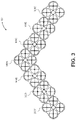
- FIG. 3 depicts a top-down view of a collective UAV configuration, according to an implementation.
- FIG. 4 depicts a top-down view of another collective UAV configuration, according to an implementation.
- FIG. 5 depicts a view of another collective UAV configuration, according to an implementation.
- FIG. 6 depicts a top-down view of a collective UAV configuration with a UAV decoupling from the collective UAV, according to an implementation.
- FIG. 7 depicts a side-view of a collective UAV configuration, according to an implementation.
- FIG. 8 depicts another side-view of a collective UAV configuration, according to an implementation.
- FIG. 9 depicts a top-down view of a collective UAV arriving at a delivery area, according to an implementation.
- FIG. 10 is a flow diagram of an example collective UAV coupling process, according to an implementation.
- FIG. 11 is a flow diagram of an example collective UAV navigation process, according to an implementation.
- FIG. 12 is a flow diagram of a collective UAV decoupling process, according to an implementation.
- FIG. 13 is a flow diagram of a collective UAV planning process, according to an implementation.
- FIG. 14 is a block diagram of an illustrative implementation of a UAV control system that may be used with various implementations.
- FIG. 15 is a block diagram of an illustrative implementation of a server system that may be used with various implementations.
- the term “coupled” may refer to two or more components or UAVs connected together, whether that connection is permanent (e.g., welded) or temporary (e.g., bolted, mechanical), direct or indirect (i.e., through an intermediary), mechanical, chemical, optical, or electrical.
- horizontal flight refers to flight traveling in a direction substantially parallel to the ground (i.e., sea level), and that “vertical” flight refers to flight traveling substantially radially outward from the earth's center. It should be understood by those having ordinary skill that trajectories may include components of both “horizontal” and “vertical” flight vectors.
- a collective UAV is two or more coupled UAVs.
- a collective UAV may be used to aerially transport virtually any size, weight, or quantity of items, travel longer distances, etc. For example, rather than using one large UAV to carry a larger or heavier item, multiple smaller UAVs may couple together to form a collective UAV that is used to carry the larger or heavier item.
- a single UAV configuration may be capable of delivering a large percentage of the ordered items.
- some items may require a larger UAV that is capable of lifting and aerially transporting a larger or heavier item.
- some orders for items may specify delivery destinations that require a UAV with longer flight duration.
- the implementations described herein utilize multiple UAVs to form a collective UAV that is capable of transporting larger and/or heavier items or aerially navigating longer distances.
- UAVs that are capable of carrying an item independent of other UAVs may couple to form a collective UAV to aerially navigate as a collective UAV to a delivery area. When one or all of the UAVs reach the delivery area, the UAVs may decouple to deliver items to different delivery destinations.
- the coupled UAVs can share resources (e.g., computing resources, power, navigation, etc.), be more efficient, be more visible, generate larger radar or object detection, be more detectable by ground based radar or air traffic control, etc.
- a collective UAV that includes multiple coupled UAVs will be more visible to other aircraft as well as air traffic control, thereby improving safety for the UAVs and other aircraft.
- some of the UAVs may reduce the rotational speed of one or more of their motors, relying on the lifting force of the collective UAV, thereby reducing the overall energy consumed during aerial navigation.
- FIG. 1 illustrates a view of a UAV 100 , according to an implementation.
- the UAV 100 includes a frame 104 .
- the frame 104 or body of the UAV 100 may be formed of any suitable material, such as graphite, carbon fiber, aluminum, titanium, etc., or any combination thereof.
- the frame 104 of the UAV 100 is a single carbon fiber frame.
- the frame 104 includes a hub 106 , motor arms 108 , motor mounts 111 , support arms 112 , and a perimeter protective barrier 114 .
- a UAV may include additional or fewer hubs, motor arms, motor mounts, support arms, or protective barriers.
- Each of the motor arms 108 extend from the hub 106 and couple with or terminate into the motor mounts 111 .
- Lifting motors 116 are coupled to an inner side of the motor mount 111 so that the lifting motor 116 and corresponding lifting propeller 118 are within the frame 104 .
- the lifting motors 116 are mounted so that the propeller shaft of the lifting motor that mounts to the lifting propeller 118 is facing downward with respect to the frame 104 .
- the lifting motors may be mounted at other angles with respect to the frame 104 of the UAV 100 .
- the lifting motors may be any form of motor capable of generating enough rotational speed with the propellers to lift the UAV 100 and an engaged payload, thereby enabling aerial transport of the payload.
- the lifting propellers 118 may be any form of propeller (e.g., graphite, carbon fiber) and of a size sufficient to lift the UAV 100 and any payload engaged by the UAV 100 so that the UAV 100 can navigate through the air, for example, to deliver a payload to a delivery destination.
- the lifting propellers 118 may each be carbon fiber propellers having a dimension or diameter of twenty-nine inches. While the illustration of FIG. 1 shows the lifting propellers 118 all of a same size, in some implementations, one or more of the lifting propellers 118 may be different sizes and/or dimensions.
- lifting propellers 118 may be utilized as lifting propellers 118 .
- the lifting propellers 118 may be positioned at different locations on the UAV 100 .
- alternative methods of propulsion may be utilized as “motors” in implementations described herein. For example, fans, jets, turbojets, turbo fans, jet engines, internal combustion engines, and the like may be used (either with propellers or other devices) to provide lift for the UAV.
- each motor mount 111 Extending from each motor mount 111 are three support arms 112 that couple with or otherwise terminate into the perimeter protective barrier 114 .
- the perimeter protective barrier 114 extends around the perimeter of the UAV and encompasses the lifting propellers 118 .
- the perimeter protective barrier 114 may include a vertical component that extends substantially downward from the support arms and approximately perpendicular to the axis of rotation of the lifting propellers 118 .
- the vertical component may be of any vertical dimension and width.
- the vertical component may have a vertical dimension of approximately three inches and a width of approximately 0.5 inches. In other implementations, the vertical dimension and/or the width may be larger or smaller.
- the vertical component of the perimeter protective barrier may include a core, such as a foam, wood and/or plastic core.
- the vertical component may be coupled to each of the support arms and extend around the outer perimeter of each propeller 118 to inhibit access to the propellers from the sides of the UAV 100 .
- the perimeter protective barrier 114 provides safety for objects foreign to the UAV 100 by inhibiting access to the propellers 118 from the side of the UAV 100 , provides protection to the UAV 100 and increases the structural integrity of the UAV 100 . For example, if the UAV 100 is traveling horizontally and collides with a foreign object (e.g., wall, building), the impact between the UAV and the foreign object will be with the perimeter protective barrier 114 , rather than a propeller. Likewise, because the frame is interconnected, the forces from the impact are dissipated across the frame 104 .
- a foreign object e.g., wall, building
- the perimeter protective barrier 114 provides a surface upon which one or more components of the UAV may be mounted.
- one or more antennas may be mounted to the perimeter protective barrier 114 .
- the antennas may be used to transmit and/or receive wireless communications.
- the antennas may be utilized for Wi-Fi, satellite, near field communication (“NFC”), cellular communication, or any other form of wireless communication.
- Other components such as cameras, time of flight sensors, distance determining elements, gimbals, Global Positioning System (“GPS”) receiver/transmitter, radars, illumination elements, speakers, and/or any other component of the UAV 100 or the UAV control system (discussed below), etc., may likewise be mounted to the perimeter protective barrier 114 .
- identification or reflective identifiers may be mounted to the vertical component to aid in the identification of the UAV 100 .
- the perimeter protective barrier 114 may also include one or more coupling components 122 .
- the coupling components may be configured to enable coupling between the UAV 100 and another UAV to form a collective UAV.
- the entire protective barrier 114 may include coupling components, thereby enabling coupling of UAVs at any position and/or orientation with the UAV 100 .
- the coupling component may provide any form of coupling sufficient to engage two or more UAVs together.
- the coupling component may include a mechanical coupling, an electrical coupling, an electromechanical coupling, a magnetic coupling, an electromagnetic coupling, etc.
- the protective barrier 114 may include a series of electromagnets that may be activated by the UAV control system 110 to couple the UAV 100 with another UAV or deactivated to decouple the UAV 100 from another UAV.
- the coupling may be a static or stationary coupling such as a series of latches or grooves that mate together to couple two or more UAVs.
- the coupling components 122 may be on the side, top, or bottom of the perimeter protective barrier 114 to enable coupling of other UAVs at different angles or orientations.
- the UAV 100 may include a coupling component on a top of the mounting plate 120 so that the UAV 100 may be coupled with a second UAV in a vertical configuration.
- An example collective UAV configuration with UAVs coupled in different orientations is illustrated in FIG. 5 .
- the coupling components 122 could be hinged or otherwise configured to allow pivoting or rotation between coupled UAVs.
- the coupling components may allow one or more degrees of freedom in rotation between coupled UAVs to allow the collective UAV configuration to flex or adjust as it navigates.
- the coupling component 122 may provide electrical and/or data communication between coupled UAVs.
- UAVs may exchange navigation information and/or share computing resources via a data transmission between the coupling components 122 of the coupled UAVs.
- power resources may be shared via the coupling components 122 of the UAVs.
- the UAV 100 may have excess power supply stored in the power modules. While the UAV 100 is coupled with another UAV, it may provide the excess power supply to the coupled UAV via the connection component 122 .
- the perimeter protective barrier may have other configurations.
- the perimeter protective barrier may be angled (e.g., forty-five degree angle) with respect to the UAV 100 , and extend from above the lifting propellers where it is coupled with the support arms 112 to below the lifting propellers 118 .
- the angles on different sides of the UAV 100 may extend in opposite directions.
- Other UAVs may couple with the UAV 100 by aligning an opposing angled side with a side of the UAV 100 and coupling the coupling components between the two UAVs.
- Such a configuration may improve the aerodynamics of the UAV 100 and/or a collective UAV configuration.
- the perimeter protective barrier may have other configurations or designs.
- the frame 104 provides structural support for the UAV 100 .
- the resulting frame has structural stability and is sufficient to support the lifting motors, lifting propellers, a payload (e.g., items), UAV control system, and/or other components of the UAV.
- the frame 104 may also include a permeable material (e.g., mesh, screen) that extends over the top and/or lower surface of the frame to inhibit vertical access to the propellers from above or below the propellers 118 .
- a permeable material e.g., mesh, screen
- one or more mounting plates 120 may be affixed to the frame 104 to provide additional surface area for mounting components to the UAV 100 .
- the mounting plates 120 may be removably coupled to the frame 104 , for example, using screws, fasteners, etc.
- the mounting plates 120 may be formed as part of the frame 104 .
- a UAV control system 110 is also mounted to the frame 104 .
- the UAV control system 110 is mounted between the hub 106 and a mounting plate 120 .
- the UAV control system 110 controls the operation, routing, navigation, communication, motor controls, resource sharing, coupling components 122 , and the payload engagement mechanism of the UAV 100 .
- the UAV 100 includes one or more power modules (not shown).
- the power modules may be mounted to various locations on the frame. For example, in some implementations, four power modules may be mounted to each mounting plate 120 and/or to the hub 106 of the frame.
- the power modules for the UAV 100 may be in the form of battery power, solar power, gas power, super capacitor, fuel cell, alternative power generation source, or a combination thereof.
- the power modules may each be a 6000 mAh lithium-ion polymer battery, or polymer lithium ion (Li-poly, Li-Pol, LiPo, LIP, PLI or Lip) battery.
- the power module(s) are coupled to and provide power for the UAV control system 110 , the lifting motors 116 , the payload engagement mechanism, the coupling components 122 , etc.
- one or more of the power modules may be configured such that it can be autonomously removed and/or replaced with another power module while the UAV is landed or in flight. For example, when the UAV lands at a location, the UAV may engage with a charging member at the location that will recharge the power module. As another example, when the UAV is coupled to and part of a collective UAV, it may receive excess power from another coupled UAV and utilize that excess power to provide power to the UAV 100 components and/or to re-charge the power module(s) of the UAV 100 .
- the UAV 100 may also include a payload engagement mechanism (not shown).
- the payload engagement mechanism may be configured to engage and disengage items and/or containers that hold items.
- the payload engagement mechanism is positioned beneath and coupled to the hub 106 of the frame 104 of the UAV 100 .
- the payload engagement mechanism may be of any size sufficient to securely engage and disengage containers that contain items.
- the payload engagement mechanism may operate as the container, in which it contains item(s).
- the payload engagement mechanism communicates with (via wired or wireless communication) and is controlled by the UAV control system 110 .
- the payload engagement mechanism may be configured to operate in conjunction with payload engagement mechanisms of other UAVs that are coupled to form a collective UAV to engage/disengage larger items.
- the UAV 100 discussed herein utilize propellers to achieve and maintain flight
- the UAV may be configured in other manners.
- the UAV may include fixed wings and/or a combination of both propellers and fixed wings.
- FIG. 2 depicts a top-down view of a plurality of UAVs 200 forming a collective UAV 202 , according to an implementation.
- two UAVs 200 A, 200 B wirelessly communicate to determine if they should couple to form a collective UAV 202 .
- each UAV 200 may exchange flight plan information, configuration information, etc., to determine if forming a collective UAV is beneficial.
- the flight plans of each UAV are complementary, it may be determined that the UAVs should couple to form a collective UAV 200 .
- Flight plans may be determined to be complementary if the UAVs 200 are navigating in a similar direction, toward a similar destination (e.g., materials handling facility, delivery area, etc.), coupling would result in a net power savings, coupling would result in increased safety, coupling would result in faster aerial transport, etc. For example, if UAV 200 A and UAV 200 B are both navigating to the same materials handling facility, it may be determined that their flight plans are complementary.
- a similar destination e.g., materials handling facility, delivery area, etc.
- UAV 200 A is navigating to a first delivery area and UAV 200 B is navigating to a second delivery area, it may be determined that the flight plans of the two UAVs 200 A, 200 B are complementary if UAV 200 B will pass the first delivery area within a defined distance as it navigates to the second delivery area.
- UAVs should couple. For example, the remaining power of each UAV may be considered, weather and/or other external factors may also be considered. For example, if the UAVs are in an area with other aircraft, it may be determined that the UAVs should couple to form a collective UAV to increase visibility of the UAVs to other aircraft.
- the UAVs will determine a collective UAV configuration and then couple according to that collective UAV configuration to form a collective UAV 200 .
- the collective UAV configuration may be determined by one or more of the UAVs 200 A, 200 B, and/or may be determined by a collective UAV configuration system 1528 ( FIG. 15 ) operating on a remote computing resource and provided wirelessly to one or more of the UAVs 200 A, 200 B.
- the UAVs 200 A, 200 B may determine or receive from the collective UAV configuration system 1528 combined operating information and a collective flight plan. For example, if the two UAVs 200 A, 200 B are navigating to the same materials handling facility, one or more of the UAVs may determine a collective UAV flight plan that is to be followed by each UAV to navigate the collective UAV to the materials handling facility.
- the UAVs may operate in a distributed manner, each UAV navigating a component or offset of the flight plan and controlling the motors of the UAV.
- one or more of the UAVs may control the collective UAV configuration.
- UAV 200 A may be designated as the master UAV of the collective UAV 202 and provide speed control instructions to the motors of the UAV 200 A and the motors of the UAV 200 B, to control the operation and navigation of the collective UAV 202 .
- data may be exchanged between the UAVs through the coupling components that couple the UAVs and/or transmitted wirelessly.
- one or more components of the slave UAV 200 B such as the control system, may transition to a lower power state, thereby conserving power.
- one or more of the UAVs 200 A, 200 B may also determine if the rotational speed of one or more of the motors of the UAV may be reduced or terminated. For example, because UAV 200 A has coupled with UAV 200 B, the collective UAV 202 has eight motors and propellers.
- the rotational speed of the interior motors 216 - 2 , 216 - 3 , 216 - 6 , 216 - 7 and corresponding interior propellers 218 - 2 , 218 - 3 , 218 - 6 , 218 - 7 of the collective UAV 202 may be reduced or terminated and the exterior motors 216 - 1 , 216 - 4 , 216 - 5 , 216 - 8 and corresponding exterior propellers 218 - 1 , 218 - 4 , 218 - 5 , 218 - 8 may be utilized to aerially navigate the collective UAV 202 .
- any number or combination of UAVs may couple to form any size and configuration of a collective UAV 202 .
- a third UAV 200 C wirelessly communicates with the collective UAV 202 and then couples with and becomes part of the collective UAV 202 .
- the UAVs 200 may directly communicate, exchanging UAV configurations, collective UAV configuration, flight plan information, etc.
- the collective UAV configuration system 1528 may wirelessly send instructions to the collective UAV 202 and/or the UAV 200 C instructing the coupling of the UAV 200 C to the collective UAV 202 .
- a UAV 200 C may couple with one or more UAVs that form a collective UAV 202 . As illustrated in FIG. 2 , the UAV 200 C has coupled with both UAV 200 A and UAV 200 B according to a determined collective UAV configuration.
- the collective UAV configuration may take any form and may vary depending on, for example, the number of UAVs forming the collective UAV, the weather, the number and/or weight of items carried by UAVs of the collective UAV, power requirements, whether one or more of the UAVs of the collective UAV is damaged or inoperable, etc.
- FIG. 3 depicts a top-down view of a collective UAV 302 having a “V” configuration, according to an implementation.
- the collective UAV 302 in this example, includes seven UAVs 300 A, 300 B, 300 C, 300 D, 300 E, 300 F, 300 G that are coupled to form the collective UAV 302 .
- Each UAV 300 is coupled to one other UAV of the collective UAV.
- the V configuration of the collective UAV may be utilized to provide better aerodynamics, benefit from lift from leading UAVs of the collective UAV, and/or reduce the overall power consumed by the collective UAV.
- FIG. 4 depicts another top-down view of a collective UAV 402 having a different configuration, according to an implementation.
- each UAV is coupled to at least one other UAV to form the collective UAV 402 .
- Some of the UAVs are coupled to up to six different UAVs.
- the coupling components that couple one or more of the UAVs 400 of the collective UAV 402 may allow one or more degrees of freedom of rotation at the coupling.
- the leading perimeter UAVs 400 may begin the adjustment and the coupling between those leading perimeter UAVs 400 may allow flex between the leading perimeter UAVs and the UAVs 400 to which they are coupled.
- the other coupled UAVs 400 will likewise adjust until the adjustment of the collective UAV 402 has completed.
- FIG. 5 is another illustration of a collective UAV 502 , according to an implementation.
- the collective UAV 502 illustrates UAVs coupled at different orientations.
- the collective UAV 502 is in the form of a cube that includes a total of twenty-four UAVs 500 coupled to form the cube; each side of the cube including four UAVs 500 .
- FIG. 5 illustrates the collective UAV 502 in the form of a cube
- the collective UAV may be arranged to have any shape.
- the UAVs may couple to form a sphere shaped collective UAV 502 .
- the collective UAV 502 includes larger surface area on each side of the collective UAV 502 making it more detectable by other aircraft and/or flight control systems.
- the propellers of the UAVs on different sides of the collective UAV 502 may be utilized to adjust the heading, pitch, yaw, and/or roll of the UAV.
- one or more of the propellers on a side of the collective UAV 502 may be utilized to provide horizontal thrust to propel the collective UAV in a direction that includes a horizontal component.
- the propellers of the UAVs 500 A, 500 B, 500 C, and 500 D that are coupled to form a side of the collective UAV 502 may be utilized to provide horizontal thrust for the collective UAV 502 .
- the propellers on the top and/or bottom of the collective UAV 502 may provide lifting force to lift the collective UAV 502 .
- the UAVs of a collective UAV may share resources, reduce rotational speed of one or more motors, and/or otherwise function as a collective to reduce the overall power consumed by the collective UAV and/or to extend the distance or time the collective UAV may aerially navigate.
- the interior UAVs such as UAV 400 A
- UAV 400 A is coupled to six other UAVs and may be able to reduce and/or terminate the rotation of the motors of the UAV 400 A and be supported by the other UAVs 400 of the collective UAV 402 , thereby conserving power.
- UAV 400 B which is on the perimeter of the collective UAV 402 , may maintain rotational speed of some or all of its motors to provide sufficient lift to aerially navigate the collective UAV 402 .
- UAV 400 B may operate in conjunction with each of the other UAVs 400 coupled along the perimeter of the collective UAV 402 .
- a collective UAV may operate in a distributed manner, with each UAV maintaining and operating the motors and/or other components of the UAV.
- the collective UAV may operate in a master-slave configuration in which one of the UAVs of the collective UAV operates as a master, providing navigation instructions, motor speed control instructions, etc., to the other UAVs of the collective UAV.
- Any control scheme may be utilized to maintain the operation and control of the collective UAV and the distributed configuration and master-slave configuration are provided only as examples.
- the collective UAV configuration system 1528 may provide navigation instructions to each of the UAVs of the collective UAV.
- FIG. 6 depicts a top-down view of a collective UAV 602 with a UAV 600 B decoupling from the collective UAV, according to an implementation.
- the collective UAV 602 includes three coupled UAVs 600 A, 600 B, 600 C that are aerially navigating along a flight path.
- UAV 600 B decouples from the collective UAV 602 .
- UAV 600 B may have reached a point in the flight path where it is to decouple from the collective UAV and navigate to another location (e.g., delivery destination).
- the UAV 600 B may resume aerial navigation utilizing its own UAV control system to aerially navigate to a destination.
- the collective UAV 602 determines the updated collective UAV configuration and/or whether the remaining UAVs 600 A, 600 C of the collective UAV 602 should reconfigure into a different configuration. For example, upon decoupling of UAV 600 B, the remaining UAVs 600 A, 600 C are coupled with one coupling component and offset from one-another. Because this may not be a preferred UAV configuration, it may be determined that the UAVs 600 A, 600 C should decouple and then recouple to form a different UAV configuration, as illustrated. In other implementations, the UAVs may remain in the existing configuration.
- any UAV of a collective UAV may decouple.
- the UAV 400 A may decouple from the collective UAV 402 .
- the collective UAV 402 may reconfigure, another UAV that is either already coupled with the collective UAV or requesting to couple with the UAV may be instructed to assume the position of the now decoupled UAV 400 A, or an empty space may be left in the collective UAV 402 .
- one or more UAVs of a collective UAV may carry a payload (e.g., item or item package) or multiple UAVs of the collective UAV may operate together to carry a single payload.
- FIG. 7 depicts a side-view of a collective UAV configuration 702 , according to an implementation.
- each UAV 700 A, 700 B, 700 C, 700 D is carrying a respective payload 704 A, 704 B, 704 C, 704 D.
- the UAVs 700 of the collective UAV 702 may all be navigating to a delivery area in which they will deliver the respective payload 704 to a delivery destination within that delivery area.
- the UAVs 700 may couple to form the collective UAV 702 as they aerially navigate from a location (e.g., materials handling facility) until they reach the delivery area. As the collective UAV reaches the delivery area, one or more of the UAVs 700 may decouple and complete delivery of the payload to the delivery destination.
- a location e.g., materials handling facility
- UAVs may couple with other UAVs to form a collective UAV to aerially navigate from the delivery area.
- the UAVs 700 may couple back together to form the collective UAV 702 and aerially navigate to another location (e.g., return to the materials handling facility).
- FIG. 8 depicts another side-view of a collective UAV 802 configuration, according to an implementation.
- two of the UAVs 800 B, 800 C are coupled to a single payload 804 and two other UAVs 800 A, 800 D are coupled to UAVs 800 B, 800 C, but do not have any coupled payloads.
- the payload 804 is heavier than a single UAV can aerially transport, so two UAVs 800 B, 800 C are coupled to form a collective UAV that is coupled to the payload 804 to enable aerial transport of the payload 804 .
- the delivery destination is beyond the range that two coupled UAVs 800 B, 800 C can reach under their own power so two additional UAVs 800 A, 800 D are coupled with the UAVs 800 B, 800 C to form the collective UAV 802 to enable aerial transport of the payload 804 .
- the collective UAV may aerially navigate the payload to a delivery area.
- the two UAVs 800 B, 800 C may decouple from the other two UAVs 800 A, 800 D to complete delivery of the payload 804 to a delivery destination.
- the two UAVs 800 B, 800 C may recouple with the two UAVs 800 A, 800 D to aerially navigate together to another location.
- Decoupling one or more of the UAVs from the collective UAV to complete delivery of the item improves the safety around the delivery destination and increases the agility of the UAV or collective UAV as it delivers the item to the delivery destination.
- the collective UAV may be several feet wide.
- the collective UAV 402 will be approximately ten feet wide by approximately eight feet long.
- the collective UAV 502 will be approximately four feet wide by approximately four feet long by approximately four feet tall.
- the collective UAV configuration improves visibility and safety while the UAV is at high altitudes by making it more visible to other aircraft, such a large configuration may not be desirable at low altitudes during item delivery. For example, if a user has ordered an item and specified a location in the backyard of their home as the delivery destination, it may be dangerous to attempt to deliver the item with a collective UAV that is approximately ten feet wide by eight feet long. In contrast, delivery with a single UAV that is approximately two feet wide by two feet long may be much safer.
- FIG. 9 depicts a top-down view of a collective UAV 902 arriving at a delivery area 904 , according to an implementation.
- the UAVs 900 A, 900 B, 900 C may decouple and complete delivery of payload carried by the UAV to a delivery destination 906 .
- UAV 900 A may decouple from the collective UAV 902 and complete delivery of a payload to delivery destination 906 A.
- UAV 900 B may decouple from the collective UAV 902 and complete delivery of a payload to delivery destination 906 B.
- UAV 900 C may decouple from the collective UAV and complete delivery of a payload to delivery destination 906 C.
- some UAVs of the collective UAV 902 may be aerially navigating past the delivery area 904 to a second delivery area to complete delivery of payloads to delivery destinations within that second delivery area.
- some of the UAVs of the collective UAV may only provide support for the aerial transport of the collective UAV and may not carry any payload for delivery.
- some of the UAVs may carry as a payload additional power modules that may be utilized by the collective UAV to extend the flight duration and/or distance of the collective UAV.
- one of the UAVs may be configured as a master UAV of the collective UAV and be configured to aid in the aerial navigation of the collective UAV to the delivery area.
- FIG. 10 is a flow diagram of an example collective UAV coupling process 1000 , according to an implementation.
- This process, and each process described herein, may be implemented by the architectures described herein or by other architectures.
- the process is illustrated as a collection of blocks in a logical flow graph. Some of the blocks represent operations that can be implemented in hardware, software, or a combination thereof.
- the blocks represent computer-executable instructions stored on one or more computer readable media that, when executed by one or more processors, perform the recited operations.
- computer-executable instructions include routines, programs, objects, components, data structures, and the like that perform particular functions or implement particular abstract data types.
- the computer readable media may include non-transitory computer readable storage media, which may include hard drives, floppy diskettes, optical disks, CD-ROMs, DVDs, read-only memories (ROMs), random access memories (RAMs), EPROMs, EEPROMs, flash memory, magnetic or optical cards, solid-state memory devices, or other types of storage media suitable for storing electronic instructions.
- the computer readable media may include a transitory computer readable signal (in compressed or uncompressed form). Examples of computer readable signals, whether modulated using a carrier or not, include, but are not limited to, signals that a computer system hosting or running a computer program can be configured to access, including signals downloaded through the Internet or other networks.
- the example process 1000 may be performed by a UAV, a collective UAV, and/or the collective UAV configuration system 1528 ( FIG. 15 ). While the example discussed below with respect to FIG. 10 describes two UAVs, in other implementations, the example process may be used with a UAV and a collective UAV, or two collective UAVs.
- the example process 1000 begins by determining a first UAV within a defined distance of a second UAV, as in 1002 .
- the defined distance may be any defined distance between UAVs (e.g., one mile).
- flight plans of the UAV(s) is received, as in 1004 .
- the two UAVs may each transmit flight plans.
- the collective UAV configuration system may periodically receive and/or determine flight plans for the UAVs.
- the example process 1000 completes, as in 1018 . However, if it is determined that the flight plans are complementary and that the UAVs should couple, a collective UAV configuration is determined, as in 1012 . As discussed above, any collective UAV configuration may be determined.
- the first UAV and the second UAV couple to form a collective UAV according to the determined collective UAV configuration, as in 1014 .
- the flight plans are also updated or a single flight plan for the collective UAV is determined based on the destinations of each UAV, as in 1016 . For example, if the two UAVs are navigating to different destinations that are separated by a distance, a collective UAV flight plan may be determined that causes that collective UAV to aerially navigate to a point between the two destinations before the two UAVs decouple and complete navigation independently to the respective destinations. In some implementations, the point between the destinations may be a midpoint.
- the point between the destinations may be determined based on the location of the destinations, the power and navigation capabilities of the UAVs, the delivery time for the UAVs, etc. For example, a first UAV may have more power remaining than a second UAV so the flight plan may instruct the collective UAV to navigate toward the destination of the first UAV and for the second UAV to decouple at a point along the flight plan to complete navigation to the destination of the second UAV.
- FIG. 11 is a flow diagram of an example collective UAV navigation process 1100 , according to an implementation.
- the example process 1100 begins by detecting a coupling of a UAV with the collective UAV, as in 1102 .
- a UAV may be instructed to couple with the collective UAV according to a collective UAV configuration.
- the coupling is detected by at least one other UAV of the collective UAV.
- a first UAV of the collective UAV to which a second UAV couples may determine that the second UAV has coupled with the collective UAV.
- the UAV configuration information of the coupled UAV is received from the coupled UAV, as in 1104 .
- the UAV configuration information may include a UAV identifier, navigation information, power supply capabilities, motor and propeller configuration, weight of the UAV and/or payload, the location of the UAV's sensors, etc.
- the collective UAV configuration information may be provided to the coupled UAV, as in 1106 .
- the collective UAV configuration information may identify, for example, the navigation information of the collective UAV, operating parameters, the configuration of the collective UAV, the sensor locations of sensors that are being used by the collective UAV, etc.
- the configuration of the collective UAV may be updated to include the coupled UAV, as in 1108 .
- a determination may be made as to whether any resources should be distributed or redistributed based on the addition of a UAV to the collective UAV, as in 1110 .
- one or more resources e.g., power, motors/propellers, control systems, etc.
- UAVs on the perimeter of a collective UAV may operate their motors to provide the lifting force to aerially navigate the collective UAV.
- the rotational speed of motors of internal UAVs and/or the internal motors of perimeter UAVs may be reduced or terminated to conserve power. Accordingly, when a UAV couples with a collective UAV, it may be determined whether resources are to be distributed or redistributed. For example, the UAV that coupled with the collective UAV may be instructed to continue rotating its motors and propellers to provide lift and another UAV may be instructed to reduce or terminate the rotation of its motors and corresponding propellers.
- the flight plan of the collective UAV is updated, as in 1112 .
- the heading of the collective UAV may be adjusted to account for the destination of the added UAV and/or may be adjusted based on the power capabilities of the added UAV.
- the example process 1100 then completes, as in 1114 .
- FIG. 12 is a flow diagram of a collective UAV decoupling process 1200 , according to an implementation.
- the example process 1200 begins when a decoupling of a UAV from the collective UAV is determined, as in 1202 .
- a UAV may decouple from the collective UAV to, for example, complete delivery of a payload to a delivery destination.
- the decoupling is detected by at least one other UAV of the collective UAV.
- a first UAV of the collective UAV from which a second UAV decoupled may determine that the second UAV has decoupled from the collective UAV.
- the second UAV may provide a notification that it is decoupling from the collective UAV.
- the updated collective UAV configuration is determined for the collective UAV, as in 1204 .
- a determination is made as to whether the collective UAV should reconfigure, as in 1206 . For example, as discussed above with respect to FIG. 6 , if the remaining UAVs of the collective UAV may be reconfigured in a manner that provides more efficiency, power savings, etc., it may be determined that the collective UAV is to be reconfigured.
- the collective UAV If it is determined that the collective UAV is to reconfigure, instructions are sent to the UAV that remain part of the collective UAV to complete the reconfiguration of the collective UAV, as in 1208 .
- the updated collective UAV configuration is determined, as in 1210 .
- the resources of the collective UAV are distributed and/or redistributed according to the updated UAV configuration, as in 1212 .
- one or more resources e.g., power, motors/propellers, control systems, etc.
- UAVs on the perimeter of a collective UAV may operate their motors to provide the lifting force to aerially navigate the collective UAV.
- the rotational speed of motors of internal UAVs and/or the internal motors of perimeter UAVs may be reduced or terminated to conserve power.
- a UAV decouples from a collective UAV it may be determined whether resources are to be distributed or redistributed. For example, if the UAV that decoupled from the collective UAV was on the perimeter and providing lifting force for the collective UAV, it may be determined that the resources of the collective UAV need to be redistributed so that a remaining UAV can assume the responsibility of rotating its motors and corresponding propellers to provide lifting force for the collective UAV.
- the flight plan of the collective UAV is updated, as in 1214 .
- the heading of the collective UAV may be adjusted to account for the decoupling of the UAV.
- the example process 1200 then completes, as in 1216 .
- FIG. 13 is a flow diagram of an example collective UAV planning process 1300 , according to an implementation.
- the example collective UAV planning process 1300 may be performed by the collective UAV configuration system 1528 .
- the collective UAV configuration system 1528 may perform that collective UAV planning process while items are being packaged for delivery at a materials handling facility to determine a collective UAV that will aerially navigate from the materials handling facility to a delivery area.
- the example process 1300 begins by determining UAVs that have or will have complementary flight plans during a defined time window, as in 1302 .
- items ordered by customers may each have similar delivery expectations and/or delivery times.
- an approximate departure time can be determined for the UAVs that will transport the items. If the approximate departure time is within the defined time window and the flight plans are complementary, the UAVs may be selected for forming a collective UAV.
- a collective UAV configuration is determined, as in 1304 .
- the collective UAV configuration may specify the shape of the configuration and where in the collective UAV configuration each UAV is to be positioned.
- the positioning of the UAVs in the collective UAV configuration may be determined based on the power capabilities of the UAVs, the motors, propellers and/or lifting capabilities of the UAVs, the size of the UAVs, the payload weight of the UAVs, the location of the delivery destinations of the UAVs, etc. For example, UAVs that will decouple first from the collective UAV may be positioned on a perimeter of the collective UAV.
- a collective UAV resource distribution is determined for the collective UAV, as in 1306 . Similar to positioning of the UAVs in the collective UAV configuration, resource distribution may be determined based on, for example, the power capabilities of the UAVs, the motors, propellers and/or lifting capabilities of the UAVs, the size of the UAVs, the payload weight of the UAVs, the location of the delivery destinations of the UAVs, etc. For example, UAVs that will have excess power based on the distance to their delivery destination and/or payload weight, may be instructed to provide power to other UAVs of the collective UAV to enable operation of the collective UAV.
- instructions are sent to each UAV that is be included in the collective UAV to configure into the collective UAV and distribute resources according to the determined resource distribution, as in 1308 .
- the instructions may be sent to the UAVs as the ordered items are packed and prepared for departure, as part of their navigation instructions, etc.
- the example process 1300 completes, as in 1310 .
- FIG. 14 is a block diagram illustrating an example UAV control system 110 .
- the block diagram may be illustrative of one or more aspects of the UAV control system 110 that may be used to implement the various systems and methods discussed herein and/or to control operation of the UAVs described herein.
- the UAV control system 110 includes one or more processors 1402 , coupled to a memory, e.g., a non-transitory computer readable storage medium 1420 , via an input/output (I/O) interface 1410 .
- the UAV control system 110 may also include electronic speed controls 1404 (ESCs), power supply modules 1406 , a navigation system 1407 , and/or an inertial measurement unit (IMU) 1412 .
- ESCs electronic speed controls 1404
- power supply modules 1406 power supply modules
- navigation system 1407 e.g., a navigation system
- IMU inertial measurement unit
- the IMU may be incorporated into the navigation system 1407 .
- the UAV control system 110 may also include a coupling controller 1419 configured to control the coupling component(s) that is used to couple/decouple the UAV from other UAVs.
- the UAV control system 110 may also include a payload engagement controller (not shown), a network interface 1416 , and one or more input/output devices 1417 .
- the UAV control system 110 may be a uniprocessor system including one processor 1402 , or a multiprocessor system including several processors 1402 (e.g., two, four, eight, or another suitable number).
- the processor(s) 1402 may be any suitable processor capable of executing instructions.
- the processor(s) 1402 may be general-purpose or embedded processors implementing any of a variety of instruction set architectures (ISAs), such as the ⁇ 86, PowerPC, SPARC, or MIPS ISAs, or any other suitable ISA.
- ISAs instruction set architectures
- each processor(s) 1402 may commonly, but not necessarily, implement the same ISA.
- the non-transitory computer readable storage medium 1420 may be configured to store executable instructions, data, flight plans, flight control parameters, collective UAV configuration information, UAV configuration information, and/or data items accessible by the processor(s) 1402 .
- the non-transitory computer readable storage medium 1420 may be implemented using any suitable memory technology, such as static random access memory (SRAM), synchronous dynamic RAM (SDRAM), nonvolatile/Flash-type memory, or any other type of memory.
- SRAM static random access memory
- SDRAM synchronous dynamic RAM
- program instructions and data implementing desired functions, such as those described herein, are shown stored within the non-transitory computer readable storage medium 1420 as program instructions 1422 , data storage 1424 and flight controls 1426 , respectively.
- program instructions, data, and/or flight controls may be received, sent, or stored upon different types of computer-accessible media, such as non-transitory media, or on similar media separate from the non-transitory computer readable storage medium 1420 or the UAV control system 110 .
- a non-transitory, computer readable storage medium may include storage media or memory media such as magnetic or optical media, e.g., disk or CD/DVD-ROM, coupled to the UAV control system 110 via the I/O interface 1410 .
- Program instructions and data stored via a non-transitory computer readable medium may be transmitted by transmission media or signals, such as electrical, electromagnetic, or digital signals, which may be conveyed via a communication medium such as a network and/or a wireless link, such as may be implemented via the network interface 1416 .
- transmission media or signals such as electrical, electromagnetic, or digital signals
- a communication medium such as a network and/or a wireless link, such as may be implemented via the network interface 1416 .
- the I/O interface 1410 may be configured to coordinate I/O traffic between the processor(s) 1402 , the non-transitory computer readable storage medium 1420 , and any peripheral devices, the network interface and/or other peripheral interfaces, such as input/output devices 1417 .
- the I/O interface 1410 may perform any necessary protocol, timing or other data transformations to convert data signals from one component (e.g., non-transitory computer readable storage medium 1420 ) into a format suitable for use by another component (e.g., processor(s) 1402 ).
- the I/O interface 1410 may include support for devices attached through various types of peripheral buses, such as a variant of the Peripheral Component Interconnect (PCI) bus standard or the Universal Serial Bus (USB) standard, for example.
- PCI Peripheral Component Interconnect
- USB Universal Serial Bus
- the function of the I/O interface 1410 may be split into two or more separate components, such as a north bridge and a south bridge, for example.
- some or all of the functionality of the I/O interface 1410 such as an interface to the non-transitory computer readable storage medium 1420 , may be incorporated directly into the processor(s) 1402 .
- the ESCs 1404 communicate with the navigation system 1407 and/or the IMU 1412 and adjust the rotational speed of each lifting motor to stabilize the UAV and guide the UAV along a determined flight plan.
- the navigation system 1407 may include a GPS, indoor positioning system (IPS), IMU or other similar system and/or sensors that can be used to navigate the UAV 100 to and/or from a location.
- the payload engagement controller communicates with the actuator(s) or motor(s) (e.g., a servo motor) used to engage and/or disengage items.
- the coupling controller 1419 communicates with the processor 1402 and/or other components and controls the coupling, data and/or resources sharing between the UAV and other coupled UAVs.
- the coupling component is an electromagnet
- the coupling controller 1419 may be utilized to activate the electromagnet to couple the UAV with another UAV or deactivate the electromagnet to decouple the UAV from another UAV.
- the network interface 1416 may be configured to allow data to be exchanged between the UAV control system 110 , other devices attached to a network, such as other computer systems (e.g., remote computing resources), and/or with UAV control systems of other UAVs.
- the network interface 1416 may enable communication between the UAV that includes the control system 110 and a UAV control system of another coupled UAV.
- the control system 110 may enable wireless communication between the UAV that includes the control system 110 and a UAV control system that is implemented on one or more remote computing resources.
- an antenna of a UAV and/or other communication components may be utilized.
- the network interface 1416 may enable wireless or wired communication between numerous UAVs. For example, when UAVs are coupled, they may utilize a wired communication via the coupling components to communicate.
- the network interface 1416 may support communication via wireless general data networks, such as a Wi-Fi, satellite, and/or cellular networks.
- Input/output devices 1417 may, in some implementations, include one or more displays, imaging devices, thermal sensors, infrared sensors, time of flight sensors, accelerometers, pressure sensors, weather sensors, cameras, gimbals, landing gear, etc. Multiple input/output devices 1417 may be present and controlled by the UAV control system 110 . One or more of these sensors may be utilized to assist in landing as well as to avoid obstacles during flight.
- the memory may include program instructions 1422 , which may be configured to implement the example processes and/or sub-processes described herein.
- the data storage 1424 may include various data stores for maintaining data items that may be provided for determining flight plans, landing, identifying locations for disengaging items, engaging/disengaging the pushing motors, etc.
- the parameter values and other data illustrated herein as being included in one or more data stores may be combined with other information not described or may be partitioned differently into more, fewer, or different data structures.
- data stores may be physically located in one memory or may be distributed among two or more memories.
- the UAV control system 110 is merely illustrative and is not intended to limit the scope of the present disclosure.
- the computing system and devices may include any combination of hardware or software that can perform the indicated functions.
- the UAV control system 110 may also be connected to other devices that are not illustrated, or instead may operate as a stand-alone system.
- the functionality provided by the illustrated components may, in some implementations, be combined in fewer components or distributed in additional components. Similarly, in some implementations, the functionality of some of the illustrated components may not be provided and/or other additional functionality may be available.
- instructions stored on a computer-accessible medium separate from the UAV control system 110 may be transmitted to the UAV control system 110 via transmission media or signals such as electrical, electromagnetic, or digital signals, conveyed via a communication medium such as a wireless link.
- Various implementations may further include receiving, sending, or storing instructions and/or data implemented in accordance with the foregoing description upon a computer-accessible medium. Accordingly, the techniques described herein may be practiced with other UAV control system configurations.
- FIG. 15 is a pictorial diagram of an illustrative implementation of a server system 1520 that may be used in the implementations described herein.
- the server system 1520 may include a processor 1500 , such as one or more redundant processors, a video display adapter 1502 , a disk drive 1504 , an input/output interface 1506 , a network interface 1508 , and a memory 1512 .
- the processor 1500 , the video display adapter 1502 , the disk drive 1504 , the input/output interface 1506 , the network interface 1508 , and/or the memory 1512 may be communicatively coupled to each other by a communication bus 1510 .
- the video display adapter 1502 provides display signals to a display (not shown in FIG. 15 ) permitting an agent of the server system 1520 to monitor and configure operation of the server system 1520 and/or to provide information (e.g., regarding collective configurations, navigation paths, etc.).
- the input/output interface 1506 likewise communicates with external input/output devices not shown in FIG. 15 , such as a mouse, keyboard, scanner, or other input and output devices that can be operated by an agent of the server system 1520 .
- the network interface 1508 includes hardware, software, or any combination thereof, to communicate with other computing devices.
- the network interface 1508 may be configured to provide communications between the server system 1520 and other computing devices, such as that of a materials handling facility, delivery location, and/or UAV, via a network.
- the memory 1512 generally comprises random access memory (RAM), read-only memory (ROM), flash memory, and/or other volatile or permanent memory.
- RAM random access memory
- ROM read-only memory
- BIOS binary input/output system
- the memory 1512 additionally stores program code and data for providing network services to UAVs, materials handling facilities, the inventory management system 1526 , and/or the collective UAV configuration system 1528 .
- the program instructions enable communication with a data store manager application 1521 to facilitate data exchange between the data store 1509 , the inventory management system 1526 and/or the collective UAV configuration system 1528 .
- the term “data store” refers to any device or combination of devices capable of storing, accessing, and retrieving data, which may include any combination and number of data servers, databases, data storage devices and data storage media, in any standard, distributed or clustered environment.
- the server system 1520 can include any appropriate hardware and software for integrating with the data store 1509 as needed to execute aspects of one or more applications for a collective UAV, materials handling facility, delivery location, collective UAV configuration system 1528 , and/or the inventory management system 1526 .
- the data store 1509 can include several separate data tables, databases or other data storage mechanisms and media for storing data relating to a particular aspect.
- the illustrated data store 1509 includes mechanisms for maintaining information related to operations, inventory, maps, GPS data, etc., which can be used to generate and deliver information to one or more UAVs, the inventory management system 1526 , and/or the collective UAV configuration system 1528 .
- the data store 1509 may maintain collective UAV configurations and information relating to efficiency, flight duration, etc., of UAVs when coupled according to each collective UAV configuration.
- the data store 1509 is operable, through logic associated therewith, to receive instructions from the server system 1520 and obtain, update or otherwise process data in response thereto.
- the memory 1512 may also include the inventory management system 1526 , discussed above.
- the inventory management system 1526 may be executable by the processor 1500 to implement one or more of the functions of the server system 1520 .
- the inventory management system 1526 may represent instructions embodied in one or more software programs stored in the memory 1512 .
- the inventory management system 1526 can represent hardware, software instructions, or a combination thereof.
- the memory 1512 may also include the collective UAV configuration system 1528 , discussed above.
- the collective UAV configuration system 1528 may be executable by the processor 1500 to implement one or more of the functions of the server system 1520 .
- the collective UAV configuration system 1528 may represent instructions embodied in one or more software programs stored in the memory 1512 .
- the collective UAV configuration system 1528 can represent hardware, software instructions, or a combination thereof.
- the server system 1520 in one implementation, is a distributed environment utilizing several computer systems and components that are interconnected via communication links, using one or more computer networks or direct connections.
- the server system 1520 could operate equally well in a system having fewer or a greater number of components than are illustrated in FIG. 15 .
- the depiction in FIG. 15 should be taken as being illustrative in nature and not limiting to the scope of the disclosure.
- the methods, systems, and processes may be implemented in software, hardware, or a combination thereof in other implementations. Similarly, the order of any process may be changed and various elements may be added, reordered, combined, omitted, modified, etc., in other implementations.
Landscapes
- Engineering & Computer Science (AREA)
- Aviation & Aerospace Engineering (AREA)
- Remote Sensing (AREA)
- Business, Economics & Management (AREA)
- Physics & Mathematics (AREA)
- General Physics & Mathematics (AREA)
- Mechanical Engineering (AREA)
- Economics (AREA)
- Automation & Control Theory (AREA)
- Radar, Positioning & Navigation (AREA)
- Human Resources & Organizations (AREA)
- Tourism & Hospitality (AREA)
- General Business, Economics & Management (AREA)
- Strategic Management (AREA)
- Theoretical Computer Science (AREA)
- Quality & Reliability (AREA)
- Operations Research (AREA)
- Marketing (AREA)
- Entrepreneurship & Innovation (AREA)
- Development Economics (AREA)
- Control Of Position, Course, Altitude, Or Attitude Of Moving Bodies (AREA)
- Traffic Control Systems (AREA)
Abstract
Description
Claims (21)
Priority Applications (8)
| Application Number | Priority Date | Filing Date | Title |
|---|---|---|---|
| US14/626,376 US11480958B2 (en) | 2015-02-19 | 2015-02-19 | Collective unmanned aerial vehicle configurations |
| JP2017542059A JP6437662B2 (en) | 2015-02-19 | 2016-02-18 | Configuration of collective unmanned aerial vehicles |
| PCT/US2016/018552 WO2016134193A1 (en) | 2015-02-19 | 2016-02-18 | Collective unmanned aerial vehicle configurations |
| CA2976785A CA2976785C (en) | 2015-02-19 | 2016-02-18 | Collective unmanned aerial vehicle configurations |
| EP16708046.4A EP3259648B1 (en) | 2015-02-19 | 2016-02-18 | Collective unmanned aerial vehicle configurations |
| CN201680012113.0A CN107278281B (en) | 2015-02-19 | 2016-02-18 | Collective drone configuration |
| JP2018213405A JP6765405B2 (en) | 2015-02-19 | 2018-11-14 | Configuration of collective unmanned aerial vehicles |
| US17/946,426 US20230019041A1 (en) | 2015-02-19 | 2022-09-16 | Collective unmanned aerial vehicle configurations |
Applications Claiming Priority (1)
| Application Number | Priority Date | Filing Date | Title |
|---|---|---|---|
| US14/626,376 US11480958B2 (en) | 2015-02-19 | 2015-02-19 | Collective unmanned aerial vehicle configurations |
Related Child Applications (1)
| Application Number | Title | Priority Date | Filing Date |
|---|---|---|---|
| US17/946,426 Division US20230019041A1 (en) | 2015-02-19 | 2022-09-16 | Collective unmanned aerial vehicle configurations |
Publications (2)
| Publication Number | Publication Date |
|---|---|
| US20160378108A1 US20160378108A1 (en) | 2016-12-29 |
| US11480958B2 true US11480958B2 (en) | 2022-10-25 |
Family
ID=55453311
Family Applications (2)
| Application Number | Title | Priority Date | Filing Date |
|---|---|---|---|
| US14/626,376 Active 2040-02-28 US11480958B2 (en) | 2015-02-19 | 2015-02-19 | Collective unmanned aerial vehicle configurations |
| US17/946,426 Pending US20230019041A1 (en) | 2015-02-19 | 2022-09-16 | Collective unmanned aerial vehicle configurations |
Family Applications After (1)
| Application Number | Title | Priority Date | Filing Date |
|---|---|---|---|
| US17/946,426 Pending US20230019041A1 (en) | 2015-02-19 | 2022-09-16 | Collective unmanned aerial vehicle configurations |
Country Status (6)
| Country | Link |
|---|---|
| US (2) | US11480958B2 (en) |
| EP (1) | EP3259648B1 (en) |
| JP (2) | JP6437662B2 (en) |
| CN (1) | CN107278281B (en) |
| CA (1) | CA2976785C (en) |
| WO (1) | WO2016134193A1 (en) |
Cited By (7)
| Publication number | Priority date | Publication date | Assignee | Title |
|---|---|---|---|---|
| US20180300836A1 (en) * | 2017-04-12 | 2018-10-18 | Audi Ag | Method for operating a transport system and corresponding transport system |
| US20240043143A1 (en) * | 2020-12-18 | 2024-02-08 | Theta-Space GmbH | Goods transport by means of unmanned aircraft and transport containers |
| RU2814494C1 (en) * | 2023-07-06 | 2024-02-29 | Павел Русланович Андреев | System and method for moving payload |
| US20240217679A1 (en) * | 2022-12-28 | 2024-07-04 | Universal City Studios Llc | Drone led light system |
| WO2025008683A1 (en) * | 2023-07-06 | 2025-01-09 | Pavel Ruslanovich Andreev | System and method for moving payload |
| US12420926B2 (en) | 2024-02-22 | 2025-09-23 | The Mitre Corporation | Layered multi-module autonomous systems |
| US20250353620A1 (en) * | 2022-05-27 | 2025-11-20 | Singapore University Of Technology And Design | Multi-monocopter system and method of operating thereof |
Families Citing this family (138)
| Publication number | Priority date | Publication date | Assignee | Title |
|---|---|---|---|---|
| US9384668B2 (en) | 2012-05-09 | 2016-07-05 | Singularity University | Transportation using network of unmanned aerial vehicles |
| US10577098B2 (en) * | 2014-08-22 | 2020-03-03 | Korea Aerospace Research Institute | Drone having reconfigurable shape |
| US11156010B1 (en) | 2014-09-29 | 2021-10-26 | Lawrence C Corban | Method of distributing items from a tower via unmanned aircraft |
| US10173775B2 (en) * | 2014-11-03 | 2019-01-08 | The Boeing Company | Modular thrust system |
| US9997079B2 (en) | 2014-12-12 | 2018-06-12 | Amazon Technologies, Inc. | Commercial and general aircraft avoidance using multi-spectral wave detection |
| US9761147B2 (en) | 2014-12-12 | 2017-09-12 | Amazon Technologies, Inc. | Commercial and general aircraft avoidance using light pattern detection |
| US9836053B2 (en) | 2015-01-04 | 2017-12-05 | Zero Zero Robotics Inc. | System and method for automated aerial system operation |
| US10220954B2 (en) * | 2015-01-04 | 2019-03-05 | Zero Zero Robotics Inc | Aerial system thermal control system and method |
| US10126745B2 (en) | 2015-01-04 | 2018-11-13 | Hangzhou Zero Zero Technology Co., Ltd. | System and method for automated aerial system operation |
| US10719080B2 (en) * | 2015-01-04 | 2020-07-21 | Hangzhou Zero Zero Technology Co., Ltd. | Aerial system and detachable housing |
| US10358214B2 (en) | 2015-01-04 | 2019-07-23 | Hangzhou Zero Zro Technology Co., Ltd. | Aerial vehicle and method of operation |
| ES2718029T3 (en) * | 2015-02-12 | 2019-06-27 | Airbus Defence & Space Gmbh | Ultralight plane |
| US10303415B1 (en) * | 2015-03-26 | 2019-05-28 | Amazon Technologies, Inc. | Mobile display array |
| CN107848623B (en) * | 2015-05-29 | 2021-02-09 | 维里蒂工作室股份公司 | Aircraft with a flight control device |
| US9922282B2 (en) * | 2015-07-21 | 2018-03-20 | Limitless Computing, Inc. | Automated readiness evaluation system (ARES) for use with an unmanned aircraft system (UAS) |
| KR20170014609A (en) * | 2015-07-30 | 2017-02-08 | 엘지전자 주식회사 | Mobile terminal and method of controlling the same |
| EP4001111A3 (en) * | 2015-11-10 | 2022-08-17 | Matternet, Inc. | Methods and system for transportation using unmanned aerial vehicles |
| CN107110977A (en) * | 2015-11-18 | 2017-08-29 | 深圳市大疆创新科技有限公司 | A kind of unmanned plane during flying device, air navigation aid and system |
| US10162348B1 (en) * | 2016-02-04 | 2018-12-25 | United Services Automobile Association (Usaa) | Unmanned vehicle morphing |
| US10343770B2 (en) * | 2016-03-01 | 2019-07-09 | Joe H. Mullins | Torque and pitch managed quad-rotor aircraft |
| US10553122B1 (en) * | 2016-03-22 | 2020-02-04 | Amazon Technologies, Inc. | Unmanned aerial vehicle data collection for routing |
| US20170283054A1 (en) * | 2016-03-29 | 2017-10-05 | Chengwen Chris WANG | Unmanned spatial vehicle performance |
| US10228691B1 (en) * | 2016-04-01 | 2019-03-12 | Olaeris, Inc. | Augmented radar camera view for remotely operated aerial vehicles |
| WO2017187275A2 (en) | 2016-04-24 | 2017-11-02 | Hangzhou Zero Zero Technology Co., Ltd. | Aerial system propulsion assembly and method of use |
| US12174642B2 (en) * | 2016-06-21 | 2024-12-24 | Keith Guy | Modular robotic system |
| US10460279B2 (en) * | 2016-06-28 | 2019-10-29 | Wing Aviation Llc | Interactive transport services provided by unmanned aerial vehicles |
| CN107585298A (en) * | 2016-07-06 | 2018-01-16 | 珠海天空速递有限公司 | Aerial deformable multi-rotor unmanned aerial vehicle |
| CN109479119B (en) * | 2016-07-22 | 2021-03-05 | 深圳市大疆创新科技有限公司 | System and method for UAV interactive video broadcasting |
| US10249200B1 (en) * | 2016-07-22 | 2019-04-02 | Amazon Technologies, Inc. | Deployable delivery guidance |
| USD808301S1 (en) * | 2016-08-22 | 2018-01-23 | Trend Right Research And Development Corporation | Unmanned aerial vehicle |
| US10198955B1 (en) | 2016-09-08 | 2019-02-05 | Amazon Technologies, Inc. | Drone marker and landing zone verification |
| US10049589B1 (en) * | 2016-09-08 | 2018-08-14 | Amazon Technologies, Inc. | Obstacle awareness based guidance to clear landing space |
| CN109996732A (en) | 2016-09-09 | 2019-07-09 | 沃尔玛阿波罗有限责任公司 | The system and method that interchangeably tool system is coupled with unmanned vehicle |
| CN109997161A (en) * | 2016-09-09 | 2019-07-09 | 沃尔玛阿波罗有限责任公司 | Geographic area monitoring system and method for collaboratively utilizing multiple unmanned vehicles |
| GB2568186A (en) | 2016-09-09 | 2019-05-08 | Walmart Apollo Llc | Geographic area monitoring systems and methods utilizing computational sharing across multiple unmanned vehicles |
| US10274952B2 (en) | 2016-09-09 | 2019-04-30 | Walmart Apollo, Llc | Geographic area monitoring systems and methods through interchanging tool systems between unmanned vehicles |
| CA3035762A1 (en) * | 2016-09-09 | 2018-03-15 | Walmart Apollo, Llc | Geographic area monitoring systems and methods that balance power usage between multiple unmanned vehicles |
| DE102016117611B4 (en) * | 2016-09-19 | 2020-03-05 | Airrobot Gmbh & Co. Kg | Device for the air transport of an object |
| JP2018062198A (en) * | 2016-10-11 | 2018-04-19 | 株式会社Soken | Flight device |
| KR101816285B1 (en) | 2016-10-19 | 2018-01-08 | 주식회사 주니랩 | Easy assembling drone |
| WO2018094554A1 (en) * | 2016-11-22 | 2018-05-31 | 深圳前海达闼云端智能科技有限公司 | Method for improving security of unmanned aerial vehicle transportation, and unmanned aerial vehicle, terminal, server and computer program product |
| KR101866770B1 (en) * | 2016-12-08 | 2018-06-18 | 국민대학교산학협력단 | Assemblable robot moving in the air |
| WO2018111186A1 (en) * | 2016-12-14 | 2018-06-21 | Zmijewski Peter Marek | Unmanned display assembly with method and computer readable medium |
| CN108229944A (en) * | 2016-12-15 | 2018-06-29 | 比亚迪股份有限公司 | Power supply charging method and device based on unmanned plane |
| US10324462B2 (en) | 2016-12-30 | 2019-06-18 | Intel Corporation | Drone swarm for increased cargo capacity |
| KR102612029B1 (en) * | 2017-01-03 | 2023-12-11 | 삼성전자 주식회사 | Unmanned aerial vehicle kit and system thereof |
| US10067513B2 (en) | 2017-01-23 | 2018-09-04 | Hangzhou Zero Zero Technology Co., Ltd | Multi-camera system and method of use |
| KR101781124B1 (en) * | 2017-02-14 | 2017-09-22 | 문원규 | Parts for drone frame |
| US10310501B2 (en) * | 2017-02-15 | 2019-06-04 | International Business Machines Corporation | Managing available energy among multiple drones |
| JP2018148522A (en) * | 2017-03-09 | 2018-09-20 | 株式会社Nttドコモ | Remote control apparatus and control system |
| US10593216B2 (en) * | 2017-03-22 | 2020-03-17 | International Business Machines Corporation | Methods and systems for multiple drone delivery system with in-flight handoff |
| KR101914960B1 (en) * | 2017-04-05 | 2018-11-06 | 국방과학연구소 | Ducted fan based unmanned air vehicle system |
| WO2018190823A1 (en) * | 2017-04-12 | 2018-10-18 | Ford Global Technologies, Llc | Multi-drone ground vehicle jump start |
| JP6579523B2 (en) * | 2017-05-02 | 2019-09-25 | 株式会社プロドローン | Flight function addition device and rotor unit |
| WO2019002995A1 (en) * | 2017-06-27 | 2019-01-03 | Andries Hermann Leuschner | Rotary-wing unmanned aerial vehicle |
| KR101888867B1 (en) * | 2017-07-18 | 2018-08-16 | 홍성호 | Drone type module |
| WO2019023111A1 (en) * | 2017-07-24 | 2019-01-31 | Walmart Apollo, Llc | Wireless charging and protection for unmanned delivery aerial vehicles |
| US10293936B1 (en) * | 2017-08-10 | 2019-05-21 | Keith Conn | Drone assemblies for providing shade |
| DE102017119670A1 (en) * | 2017-08-28 | 2019-02-28 | Airbus Operations Gmbh | Coupling device for coupling modules, aircraft with coupling device, method for coupling and decoupling of modules |
| US9957045B1 (en) * | 2017-09-03 | 2018-05-01 | Brehnden Daly | Stackable drones |
| JP2019085104A (en) * | 2017-11-06 | 2019-06-06 | 株式会社エアロネクスト | Flight unit and control method of flight unit |
| CN108069028A (en) * | 2017-11-30 | 2018-05-25 | 中国直升机设计研究所 | A kind of lift combining structure based on more rotor configurations |
| US10894601B2 (en) | 2017-12-20 | 2021-01-19 | Wing Aviation Llc | Methods and systems for self-deployment of operational infrastructure by an unmanned aerial vehicle (UAV) |
| KR101867424B1 (en) * | 2018-01-05 | 2018-06-14 | 주식회사 파워리퍼블릭 | Wireless power charging apparatus transmitting power wirelessly for drones airborne |
| US10766610B2 (en) | 2018-01-22 | 2020-09-08 | Mattel, Inc. | Unmanned aerial vehicle with propeller guard |
| KR101956648B1 (en) * | 2018-01-24 | 2019-03-12 | 주식회사 마케팅위너 | Module type drone |
| US10515555B2 (en) | 2018-01-31 | 2019-12-24 | Walmart Apollo, Llc | System and method for managing a swarm of unmanned aerial vehicles |
| WO2019152533A1 (en) * | 2018-01-31 | 2019-08-08 | Walmart Apollo, Llc | Cloning drones using blockchain |
| CN112041257B (en) * | 2018-03-02 | 2023-01-24 | 维斯塔斯风力系统有限公司 | Systems and methods for handling wind turbine components for their assembly |
| US10351261B1 (en) * | 2018-03-05 | 2019-07-16 | Carolyn Bryant | Autonomous drone based package reception and surveillance system |
| JP6731604B2 (en) * | 2018-03-31 | 2020-07-29 | 中松 義郎 | High-speed drones and other aircraft |
| US11970266B2 (en) | 2018-04-10 | 2024-04-30 | ACSL, Ltd. | Unmanned aerial vehicle, flight control mechanism for unmanned aerial vehicle, and method for using unmanned aerial vehicle and mechanism for unmanned aerial vehicle |
| GB2573536B (en) * | 2018-05-08 | 2021-06-02 | Khalil Rany | Reconfigurable modular drone |
| WO2019231745A1 (en) * | 2018-05-29 | 2019-12-05 | Walmart Apollo, Llc | Unmanned retail delivery vehicle protection systems and methods of protection |
| US10954679B2 (en) * | 2018-06-11 | 2021-03-23 | International Business Machines Corporation | Dynamic platform creation |
| CN112262357B (en) * | 2018-06-11 | 2024-10-18 | 瑞典爱立信有限公司 | Determining control parameters for formations of multiple UAVs |
| US20190389575A1 (en) * | 2018-06-22 | 2019-12-26 | The Boeing Company | Extended Duration Regenerative Powered Unmanned Aerial Vehicle (UAV) Platform |
| US20200033851A1 (en) * | 2018-07-27 | 2020-01-30 | California Institute Of Technology | Modular and dynamically reconfigurable flying systems encompassing flying vehicle modules |
| WO2020038356A1 (en) * | 2018-08-24 | 2020-02-27 | Hangzhou Zero Zero Technology Co., Ltd. | Detachable protection structure for unmanned aerial systems |
| WO2020049604A1 (en) * | 2018-09-06 | 2020-03-12 | Bellamoli Paolo | Modular multi-rotary wing drone powered by electric turbine generator |
| JP6714668B2 (en) * | 2018-10-15 | 2020-06-24 | Hapsモバイル株式会社 | Aircraft and systems |
| DE102018125992A1 (en) * | 2018-10-19 | 2020-04-23 | Andreas Voss | Missile and method for controlling a missile |
| NO344545B1 (en) * | 2018-10-24 | 2020-01-27 | Griff Aviation As | An aerial vehicle system and associated power generating hub |
| US11021223B2 (en) | 2018-10-26 | 2021-06-01 | California Institute Of Technology | Versatile flexible and reconfigurable vehicle systems |
| KR102115779B1 (en) * | 2018-11-15 | 2020-05-27 | 주식회사 호그린에어 | Connecting structure for drone type module |
| WO2020115514A1 (en) * | 2018-12-04 | 2020-06-11 | Aida Europe Gmbh | Production system for machining workpieces |
| KR102101636B1 (en) * | 2018-12-13 | 2020-04-20 | (주)아이앤디자인 | Dron |
| KR101986500B1 (en) * | 2018-12-17 | 2019-06-07 | 엘아이지넥스원 주식회사 | Expanded unmanned air vehicle assembly |
| KR102725575B1 (en) * | 2018-12-18 | 2024-11-05 | 현대자동차주식회사 | System comprising unmanned aerial vehicle and collaboration method thereof |
| US11150646B2 (en) * | 2019-01-22 | 2021-10-19 | Here Global B.V. | Delivery with swarming aerial vehicles |
| US11215630B2 (en) | 2019-01-22 | 2022-01-04 | Here Global B.V. | Airflow modeling from aerial vehicle pose |
| US11217104B2 (en) | 2019-01-22 | 2022-01-04 | Here Global B.V. | Airflow modeling for route optimization |
| KR102135419B1 (en) * | 2019-03-18 | 2020-07-20 | 서울과학기술대학교 산학협력단 | Detachable drones and drones docking station |
| US12071228B1 (en) * | 2019-03-28 | 2024-08-27 | Snap Inc. | Drone with propeller guard configured as an airfoil |
| US11724804B2 (en) * | 2019-04-11 | 2023-08-15 | Textron Innovations Inc. | Aircraft coupling mechanism |
| US11884175B2 (en) * | 2019-06-26 | 2024-01-30 | Robotic Research Opco, Llc | Self-powered drone tether |
| US11597515B2 (en) * | 2019-08-19 | 2023-03-07 | Epazz, Inc. | Charging/re-charging drone assembly system and apparatus |
| EP4017802A1 (en) | 2019-08-23 | 2022-06-29 | Sony Group Corporation | A method for autonomous in-flight transfer of a load from a first aerial vehicle to a second aerial vehicle, system comprising a first aerial vehicle and a second aerial vehicle, and aerial vehicles |
| WO2021056080A1 (en) * | 2019-09-27 | 2021-04-01 | Wise Networking Pty Ltd | Aerially distributable communications device |
| CN110641706B (en) * | 2019-10-31 | 2023-05-23 | 上海机电工程研究所 | Combined unmanned aerial vehicle unit based on folding combination form and combination method thereof |
| US12434682B1 (en) * | 2019-11-26 | 2025-10-07 | Owen Richard Wiseman | Hover drone system |
| FR3107253B1 (en) * | 2020-02-18 | 2022-05-20 | Taupin Sebastien | Aerial system for transporting and delivering parcels without an on-board human pilot, logistics method implemented in this system and aerostatic device integrated in this system |
| KR102427766B1 (en) * | 2020-03-25 | 2022-08-02 | 서울대학교산학협력단 | Flight module and Flight vehicle having the same |
| KR102379869B1 (en) * | 2020-06-10 | 2022-03-28 | 주식회사 엘지유플러스 | Transportation system using unmanned aerial vehicles |
| US11541984B2 (en) | 2020-07-06 | 2023-01-03 | Boy Scouts Of America | Modular flat-packable drone kit |
| US11702203B2 (en) * | 2020-07-06 | 2023-07-18 | Boy Scouts Of America | Group configurations for a modular drone system |
| US11779003B2 (en) * | 2020-10-06 | 2023-10-10 | Hcl Technologies Limited | System and method for managing an insect swarm using drones |
| JP2023553396A (en) | 2020-12-02 | 2023-12-21 | ジップライン インターナショナル インク. | System for docking, storing and loading unmanned aircraft |
| CN112859835B (en) * | 2020-12-29 | 2023-06-20 | 广东嘉腾机器人自动化有限公司 | Traffic control method using traffic control device |
| US11661192B2 (en) * | 2021-02-12 | 2023-05-30 | Aerbots, Inc. | Drones and drone systems |
| KR102347325B1 (en) * | 2021-03-09 | 2022-01-06 | 주식회사 파블로항공 | Apparatus for assisting formation flight of unmanned aerial vehicle |
| US11803196B2 (en) * | 2021-03-15 | 2023-10-31 | International Business Machines Corporation | Unmanned aerial vehicles and control thereof |
| CN113022854A (en) * | 2021-04-14 | 2021-06-25 | 马东林 | Express delivery transportation technology of 2+ N unmanned aerial vehicle queue |
| ES2984234T3 (en) * | 2021-05-03 | 2024-10-29 | Airbus Defence & Space Gmbh | Adaptable reticular structure for multi-mission drones |
| WO2022233496A1 (en) * | 2021-05-03 | 2022-11-10 | Airbus Defence and Space GmbH | An adaptable lattice structure for multi-mission drones |
| KR102583405B1 (en) * | 2021-07-05 | 2023-09-27 | 주식회사 아르고스다인 | Drone Station |
| CN113665809B (en) * | 2021-08-06 | 2024-02-02 | 北京航空航天大学 | Distributed multi-dwelling spherical unmanned system |
| DE102021123990B4 (en) * | 2021-09-16 | 2023-04-06 | HHLA Sky GmbH | landing platform |
| US12242986B2 (en) * | 2021-09-17 | 2025-03-04 | Anduril Industries, Inc. | Planning an operation for a set of assets |
| CN216805836U (en) * | 2021-11-22 | 2022-06-24 | 上海峰飞航空科技有限公司 | Modular unmanned aerial vehicle that hangs down |
| US12534231B2 (en) * | 2022-02-22 | 2026-01-27 | Arizona Board Of Regents On Behalf Of The University Of Arizona | Configurable unmanned aerial vehicle system |
| WO2023168623A1 (en) * | 2022-03-09 | 2023-09-14 | 深圳市大疆创新科技有限公司 | Unmanned aerial vehicle base station and unmanned aerial vehicle system |
| US20230347503A1 (en) * | 2022-04-29 | 2023-11-02 | Kabushiki Kaisha Toshiba | Robots with lift mechanisms |
| US12145753B2 (en) * | 2022-08-09 | 2024-11-19 | Pete Bitar | Compact and lightweight drone delivery device called an ArcSpear electric jet drone system having an electric ducted air propulsion system and being relatively difficult to track in flight |
| TWI814544B (en) * | 2022-08-18 | 2023-09-01 | 中華電信股份有限公司 | Electronic device and method for generating optimal flight trajectory based on flying point of unmanned aerial vehicle |
| JP7697435B2 (en) * | 2022-09-01 | 2025-06-24 | トヨタ自動車株式会社 | Take-off and landing assistance equipment |
| US12522367B2 (en) * | 2022-09-02 | 2026-01-13 | University Of South Carolina | Expandable drone |
| JP7621316B2 (en) * | 2022-09-14 | 2025-01-24 | 双葉電子工業株式会社 | Control device, flying vehicle system |
| RU2798089C1 (en) * | 2022-12-28 | 2023-06-15 | Павел Русланович Андреев | Aircraft (variants), self-propelled module, payload, system and method for moving the payload (variants) |
| CN116141892A (en) * | 2022-12-29 | 2023-05-23 | 北京航空航天大学云南创新研究院 | A ground-air amphibious cylindrical unmanned aerial vehicle and its control method |
| US20240269831A1 (en) * | 2023-02-15 | 2024-08-15 | International Business Machines Corporation | Dynamic formation of material handling vehicle |
| WO2024178095A2 (en) * | 2023-02-21 | 2024-08-29 | Arizona Board Of Regents On Behalf Of The University Of Arizona | Control system for a configurable unmanned aerial vehicle system |
| CN115980742B (en) * | 2023-03-20 | 2023-05-19 | 成都航空职业技术学院 | A radar detection method and device for unmanned aerial vehicles |
| CN220764753U (en) * | 2023-06-29 | 2024-04-12 | 深圳市道通智能航空技术股份有限公司 | A drone nest |
| US20250021100A1 (en) * | 2023-07-14 | 2025-01-16 | International Business Machines Corporation | Cooperative use of autonomous machines |
| US12545447B1 (en) * | 2024-06-07 | 2026-02-10 | Amazon Technologies, Inc. | Aerial vehicle landing pad with sensors |
| US20260048877A1 (en) * | 2024-08-15 | 2026-02-19 | Skydio, Inc. | Base Station For An Unmanned Aerial Vehicle Including A Rotatable Roof Assembly |
| US20260048865A1 (en) * | 2024-08-15 | 2026-02-19 | Skydio, Inc. | Method of docking an unmanned aerial vehicle with a base station |
Citations (30)
| Publication number | Priority date | Publication date | Assignee | Title |
|---|---|---|---|---|
| US3295789A (en) | 1963-11-04 | 1967-01-03 | Charlie R Hill | Airspace craft |
| JP2002211496A (en) | 2001-01-17 | 2002-07-31 | Honda Motor Co Ltd | Stratospheric platform |
| US20070102565A1 (en) | 2005-11-09 | 2007-05-10 | The Boeing Company | Air vehicle assembly and an associated control system and method |
| US20080078865A1 (en) | 2006-09-21 | 2008-04-03 | Honeywell International Inc. | Unmanned Sensor Placement In A Cluttered Terrain |
| US20100025523A1 (en) * | 2007-07-31 | 2010-02-04 | Kutzmann Aaron J | Reconfigurable aircraft and associated methods |
| WO2010021295A1 (en) | 2008-08-21 | 2010-02-25 | 三菱重工業株式会社 | Unmanned aircraft system and method of operating same |
| US20100193625A1 (en) | 2005-07-07 | 2010-08-05 | Sommer Geoffrey S | Modular articulated-wing aircraft |
| WO2011133944A1 (en) | 2010-04-22 | 2011-10-27 | Aerovironment, Inc. | Unmanned aerial vehicle and method of operation |
| WO2011149544A1 (en) | 2010-05-26 | 2011-12-01 | Aerovironment Inc. | Reconfigurable battery-operated vehicle system |
| US20120061506A1 (en) | 2007-09-14 | 2012-03-15 | Aurora Flight Sciences Corporation | Wing tip docking system for aircraft |
| US20120158215A1 (en) | 2010-02-18 | 2012-06-21 | Massachusetts Institute Of Technology | Programmable Surface |
| US20130233964A1 (en) | 2012-03-07 | 2013-09-12 | Aurora Flight Sciences Corporation | Tethered aerial system for data gathering |
| US20140032034A1 (en) | 2012-05-09 | 2014-01-30 | Singularity University | Transportation using network of unmanned aerial vehicles |
| WO2014080386A2 (en) | 2014-03-25 | 2014-05-30 | Alshdaifat, Wasfi | Drone service aero-carrier |
| WO2014096144A1 (en) | 2012-12-21 | 2014-06-26 | European Aeronautic Defence And Space Company Eads France | In-flight refuelling device for electric storage system and aircraft equipped with such a device |
| JP2014126299A (en) | 2012-12-26 | 2014-07-07 | Kawasaki Heavy Ind Ltd | Laser irradiation system using relay device |
| CN103963972A (en) | 2013-01-29 | 2014-08-06 | 中国航空工业集团公司西安飞机设计研究所 | System composed of all-wing unmanned planes capable of making wings oblique and connected in parallel through coupling of wingtips |
| US20140374532A1 (en) | 2013-06-24 | 2014-12-25 | The Boeing Company | Modular Vehicle Lift System |
| US8936212B1 (en) | 2009-08-25 | 2015-01-20 | Qiang Fu | System and method for compact and combinable aerial vehicle capable of vertical/short takeoff and landing |
| US20150120126A1 (en) | 2008-05-27 | 2015-04-30 | Wilfred So | System and method for multiple vehicles moving a common payload |
| US20150147976A1 (en) * | 2013-10-09 | 2015-05-28 | SZ DJI Technology Co., Ltd | Remote control methods and systems |
| EP2881324A1 (en) | 2013-12-09 | 2015-06-10 | The Boeing Company | Methods and apparatus to cooperatively lift a payload |
| US9079662B1 (en) | 2012-10-01 | 2015-07-14 | The Boeing Company | Co-operative, modular, unmanned, vertical lift cargo vehicles |
| KR101614620B1 (en) | 2014-12-05 | 2016-04-22 | 서울대학교산학협력단 | Aerial Robot System Based on Multi-rotor for Mechanical Tasks |
| US20160304217A1 (en) * | 2015-01-18 | 2016-10-20 | Foundation Productions, Llc | Apparatus, Systems and Methods for Unmanned Aerial Vehicles |
| US20160304199A1 (en) * | 2014-12-04 | 2016-10-20 | Elwha Llc | System and method for operation and management of reconfigurable unmanned aircraft |
| US20160351089A1 (en) | 2015-05-26 | 2016-12-01 | Mores, Inc. | Self charging lightweight drone apparatus |
| WO2017173502A1 (en) | 2016-04-07 | 2017-10-12 | Iot Group Technology Pty Ltd | Aerial devices, rotor assemblies for aerial devices, and device frameworks and methodologies configured to enable control of aerial devices |
| US9908632B1 (en) * | 2014-08-25 | 2018-03-06 | Amazon Technologies, Inc. | Adjustable unmanned aerial vehicles with multiple lifting motors and propellers |
| US10011353B1 (en) * | 2015-02-02 | 2018-07-03 | Amazon Technologies, Inc. | Maneuvering an unmanned aerial vehicle without considering the effects of gravity |
Family Cites Families (10)
| Publication number | Priority date | Publication date | Assignee | Title |
|---|---|---|---|---|
| IL157401A (en) * | 2003-08-14 | 2008-06-05 | Nir Padan | Apparatus and system for the air-to-air arming of aerial vehicles |
| RU2518877C1 (en) * | 2012-12-18 | 2014-06-10 | Открытое Акционерное Общество "Государственное Машиностроительное Конструкторское Бюро "Радуга" Имени А.Я. Березняка" | Drone |
| US9540102B2 (en) * | 2012-12-19 | 2017-01-10 | Elwha Llc | Base station multi-vehicle coordination |
| WO2015061008A1 (en) * | 2013-10-26 | 2015-04-30 | Amazon Technologies, Inc. | Unmanned aerial vehicle delivery system |
| KR101473739B1 (en) * | 2014-05-12 | 2014-12-18 | 국방과학연구소 | System and method for controlling unmaned aerial vehicle |
| US9760072B2 (en) * | 2014-07-03 | 2017-09-12 | David R. Hall | Secure remote operation and actuation of unmanned aerial vehicles |
| EP3399381A1 (en) * | 2014-09-05 | 2018-11-07 | SZ DJI Technology Co., Ltd. | Context-based flight mode selection |
| US9889930B2 (en) * | 2014-11-24 | 2018-02-13 | Amazon Technologies, Inc. | Unmanned aerial vehicle protective frame configuration |
| US20160272310A1 (en) * | 2014-12-04 | 2016-09-22 | Elwha Llc | Reconfigurable unmanned aircraft system |
| LT6953B (en) * | 2021-03-25 | 2022-10-25 | Robotopia, UAB | Method of delivery of liquid by ejecting continuous jet and system for implementing said method |
-
2015
- 2015-02-19 US US14/626,376 patent/US11480958B2/en active Active
-
2016
- 2016-02-18 CN CN201680012113.0A patent/CN107278281B/en active Active
- 2016-02-18 WO PCT/US2016/018552 patent/WO2016134193A1/en not_active Ceased
- 2016-02-18 EP EP16708046.4A patent/EP3259648B1/en active Active
- 2016-02-18 CA CA2976785A patent/CA2976785C/en active Active
- 2016-02-18 JP JP2017542059A patent/JP6437662B2/en active Active
-
2018
- 2018-11-14 JP JP2018213405A patent/JP6765405B2/en active Active
-
2022
- 2022-09-16 US US17/946,426 patent/US20230019041A1/en active Pending
Patent Citations (38)
| Publication number | Priority date | Publication date | Assignee | Title |
|---|---|---|---|---|
| US3295789A (en) | 1963-11-04 | 1967-01-03 | Charlie R Hill | Airspace craft |
| JP2002211496A (en) | 2001-01-17 | 2002-07-31 | Honda Motor Co Ltd | Stratospheric platform |
| US20100193625A1 (en) | 2005-07-07 | 2010-08-05 | Sommer Geoffrey S | Modular articulated-wing aircraft |
| US20070102565A1 (en) | 2005-11-09 | 2007-05-10 | The Boeing Company | Air vehicle assembly and an associated control system and method |
| US20080078865A1 (en) | 2006-09-21 | 2008-04-03 | Honeywell International Inc. | Unmanned Sensor Placement In A Cluttered Terrain |
| JP2008150028A (en) | 2006-09-21 | 2008-07-03 | Honeywell Internatl Inc | Unmanned sensor placement in an area with clutter. |
| US20100025523A1 (en) * | 2007-07-31 | 2010-02-04 | Kutzmann Aaron J | Reconfigurable aircraft and associated methods |
| US20120061506A1 (en) | 2007-09-14 | 2012-03-15 | Aurora Flight Sciences Corporation | Wing tip docking system for aircraft |
| US20150120126A1 (en) | 2008-05-27 | 2015-04-30 | Wilfred So | System and method for multiple vehicles moving a common payload |
| WO2010021295A1 (en) | 2008-08-21 | 2010-02-25 | 三菱重工業株式会社 | Unmanned aircraft system and method of operating same |
| US20110049288A1 (en) | 2008-08-21 | 2011-03-03 | Satoshi Suzuki | Unmanned aircraft system and operation method thereof |
| JP2010047109A (en) | 2008-08-21 | 2010-03-04 | Mitsubishi Heavy Ind Ltd | Unmanned aircraft system and method for operating the same |
| US8936212B1 (en) | 2009-08-25 | 2015-01-20 | Qiang Fu | System and method for compact and combinable aerial vehicle capable of vertical/short takeoff and landing |
| US20120158215A1 (en) | 2010-02-18 | 2012-06-21 | Massachusetts Institute Of Technology | Programmable Surface |
| JP2013525185A (en) | 2010-04-22 | 2013-06-20 | エアロバイロメント,インコーポレイテッド | Unmanned aerial vehicle and method of operation |
| WO2011133944A1 (en) | 2010-04-22 | 2011-10-27 | Aerovironment, Inc. | Unmanned aerial vehicle and method of operation |
| JP2013531573A (en) | 2010-05-26 | 2013-08-08 | エアロヴァイロンメント インコーポレイテッド | Reconfigurable battery-powered drone system |
| WO2011149544A1 (en) | 2010-05-26 | 2011-12-01 | Aerovironment Inc. | Reconfigurable battery-operated vehicle system |
| US20130233964A1 (en) | 2012-03-07 | 2013-09-12 | Aurora Flight Sciences Corporation | Tethered aerial system for data gathering |
| US20140032034A1 (en) | 2012-05-09 | 2014-01-30 | Singularity University | Transportation using network of unmanned aerial vehicles |
| US9079662B1 (en) | 2012-10-01 | 2015-07-14 | The Boeing Company | Co-operative, modular, unmanned, vertical lift cargo vehicles |
| US20150336677A1 (en) | 2012-12-21 | 2015-11-26 | European Aeronautic Defence And Space Company Eads France | In-flight refuelling device for electric storage system and aircraft equipped with such a device |
| WO2014096144A1 (en) | 2012-12-21 | 2014-06-26 | European Aeronautic Defence And Space Company Eads France | In-flight refuelling device for electric storage system and aircraft equipped with such a device |
| JP2014126299A (en) | 2012-12-26 | 2014-07-07 | Kawasaki Heavy Ind Ltd | Laser irradiation system using relay device |
| CN103963972A (en) | 2013-01-29 | 2014-08-06 | 中国航空工业集团公司西安飞机设计研究所 | System composed of all-wing unmanned planes capable of making wings oblique and connected in parallel through coupling of wingtips |
| US20140374532A1 (en) | 2013-06-24 | 2014-12-25 | The Boeing Company | Modular Vehicle Lift System |
| EP2818406A1 (en) | 2013-06-24 | 2014-12-31 | The Boeing Company | Modular vehicle lift system |
| US20150147976A1 (en) * | 2013-10-09 | 2015-05-28 | SZ DJI Technology Co., Ltd | Remote control methods and systems |
| EP2881324A1 (en) | 2013-12-09 | 2015-06-10 | The Boeing Company | Methods and apparatus to cooperatively lift a payload |
| WO2014080386A2 (en) | 2014-03-25 | 2014-05-30 | Alshdaifat, Wasfi | Drone service aero-carrier |
| US9908632B1 (en) * | 2014-08-25 | 2018-03-06 | Amazon Technologies, Inc. | Adjustable unmanned aerial vehicles with multiple lifting motors and propellers |
| US20160304199A1 (en) * | 2014-12-04 | 2016-10-20 | Elwha Llc | System and method for operation and management of reconfigurable unmanned aircraft |
| US9919797B2 (en) * | 2014-12-04 | 2018-03-20 | Elwha Llc | System and method for operation and management of reconfigurable unmanned aircraft |
| KR101614620B1 (en) | 2014-12-05 | 2016-04-22 | 서울대학교산학협력단 | Aerial Robot System Based on Multi-rotor for Mechanical Tasks |
| US20160304217A1 (en) * | 2015-01-18 | 2016-10-20 | Foundation Productions, Llc | Apparatus, Systems and Methods for Unmanned Aerial Vehicles |
| US10011353B1 (en) * | 2015-02-02 | 2018-07-03 | Amazon Technologies, Inc. | Maneuvering an unmanned aerial vehicle without considering the effects of gravity |
| US20160351089A1 (en) | 2015-05-26 | 2016-12-01 | Mores, Inc. | Self charging lightweight drone apparatus |
| WO2017173502A1 (en) | 2016-04-07 | 2017-10-12 | Iot Group Technology Pty Ltd | Aerial devices, rotor assemblies for aerial devices, and device frameworks and methodologies configured to enable control of aerial devices |
Non-Patent Citations (3)
| Title |
|---|
| International Search Report and Written Opinion of PCT/US16/18552 dated May 4, 2016. |
| Search Report dated Nov. 4, 2019, for corresponding CN Application No. 201680012113.0. |
| Smith, Scot et al. "Design Considerations for Remote Sensing Payloads on Inexpensive Unmanned Autonomous Aerial Vehicles." Surveying and land information science 70.3 (2010): 131-137. Print. (Year: 2010). * |
Cited By (10)
| Publication number | Priority date | Publication date | Assignee | Title |
|---|---|---|---|---|
| US20180300836A1 (en) * | 2017-04-12 | 2018-10-18 | Audi Ag | Method for operating a transport system and corresponding transport system |
| US12307539B2 (en) * | 2017-04-12 | 2025-05-20 | Audi Ag | Method for operating a transport system and corresponding transport system |
| US20240043143A1 (en) * | 2020-12-18 | 2024-02-08 | Theta-Space GmbH | Goods transport by means of unmanned aircraft and transport containers |
| US12497196B2 (en) * | 2020-12-18 | 2025-12-16 | Theta-Space GmbH | Goods transport by means of unmanned aircraft and transport containers |
| US20250353620A1 (en) * | 2022-05-27 | 2025-11-20 | Singapore University Of Technology And Design | Multi-monocopter system and method of operating thereof |
| US12552558B2 (en) * | 2022-05-27 | 2026-02-17 | Singapore University Of Technology And Design | Multi-monocopter system and method of operating thereof |
| US20240217679A1 (en) * | 2022-12-28 | 2024-07-04 | Universal City Studios Llc | Drone led light system |
| RU2814494C1 (en) * | 2023-07-06 | 2024-02-29 | Павел Русланович Андреев | System and method for moving payload |
| WO2025008683A1 (en) * | 2023-07-06 | 2025-01-09 | Pavel Ruslanovich Andreev | System and method for moving payload |
| US12420926B2 (en) | 2024-02-22 | 2025-09-23 | The Mitre Corporation | Layered multi-module autonomous systems |
Also Published As
| Publication number | Publication date |
|---|---|
| JP6765405B2 (en) | 2020-10-07 |
| JP6437662B2 (en) | 2018-12-12 |
| WO2016134193A1 (en) | 2016-08-25 |
| JP2018505094A (en) | 2018-02-22 |
| CA2976785C (en) | 2020-07-07 |
| EP3259648A1 (en) | 2017-12-27 |
| CA2976785A1 (en) | 2016-08-25 |
| US20230019041A1 (en) | 2023-01-19 |
| EP3259648B1 (en) | 2024-08-28 |
| US20160378108A1 (en) | 2016-12-29 |
| CN107278281B (en) | 2021-07-06 |
| CN107278281A (en) | 2017-10-20 |
| JP2019051934A (en) | 2019-04-04 |
Similar Documents
| Publication | Publication Date | Title |
|---|---|---|
| US20230019041A1 (en) | Collective unmanned aerial vehicle configurations | |
| US9760072B2 (en) | Secure remote operation and actuation of unmanned aerial vehicles | |
| US10065745B1 (en) | Electricity generation in automated aerial vehicles | |
| US12032391B2 (en) | Virtual safety shrouds for aerial vehicles | |
| US10293937B2 (en) | Unmanned aerial vehicle protective frame configuration | |
| EP3271245B1 (en) | Adjustable landing gear assembly for unmanned aerial vehicles | |
| US10822081B2 (en) | Communications and landings of unmanned aerial vehicles on transportation vehicles for transport | |
| US10908285B2 (en) | Sense and avoid for automated mobile vehicles | |
| US10410527B2 (en) | Ground effect based surface sensing using propellers in automated aerial vehicles | |
| US10780988B2 (en) | Propeller safety for automated aerial vehicles | |
| US9739870B1 (en) | Tracking unmanned aerial vehicles using reflected light |
Legal Events
| Date | Code | Title | Description |
|---|---|---|---|
| AS | Assignment |
Owner name: AMAZON TECHNOLOGIES, INC., WASHINGTON Free format text: ASSIGNMENT OF ASSIGNORS INTEREST;ASSIGNORS:PACZAN, NATHAN MICHAEL;ELZINGA, MICHAEL JOHN;HSIEH, RAPHAEL;AND OTHERS;SIGNING DATES FROM 20150311 TO 20150325;REEL/FRAME:035332/0797 |
|
| STPP | Information on status: patent application and granting procedure in general |
Free format text: ADVISORY ACTION MAILED |
|
| STCV | Information on status: appeal procedure |
Free format text: NOTICE OF APPEAL FILED |
|
| STCV | Information on status: appeal procedure |
Free format text: APPEAL BRIEF (OR SUPPLEMENTAL BRIEF) ENTERED AND FORWARDED TO EXAMINER |
|
| STPP | Information on status: patent application and granting procedure in general |
Free format text: NON FINAL ACTION MAILED |
|
| STPP | Information on status: patent application and granting procedure in general |
Free format text: RESPONSE TO NON-FINAL OFFICE ACTION ENTERED AND FORWARDED TO EXAMINER |
|
| STPP | Information on status: patent application and granting procedure in general |
Free format text: FINAL REJECTION MAILED |
|
| STPP | Information on status: patent application and granting procedure in general |
Free format text: ADVISORY ACTION MAILED |
|
| STCV | Information on status: appeal procedure |
Free format text: APPEAL BRIEF (OR SUPPLEMENTAL BRIEF) ENTERED AND FORWARDED TO EXAMINER |
|
| STCV | Information on status: appeal procedure |
Free format text: EXAMINER'S ANSWER TO APPEAL BRIEF MAILED |
|
| STCV | Information on status: appeal procedure |
Free format text: ON APPEAL -- AWAITING DECISION BY THE BOARD OF APPEALS |
|
| STCV | Information on status: appeal procedure |
Free format text: BOARD OF APPEALS DECISION RENDERED |
|
| STPP | Information on status: patent application and granting procedure in general |
Free format text: DOCKETED NEW CASE - READY FOR EXAMINATION |
|
| STPP | Information on status: patent application and granting procedure in general |
Free format text: NOTICE OF ALLOWANCE MAILED -- APPLICATION RECEIVED IN OFFICE OF PUBLICATIONS |
|
| STPP | Information on status: patent application and granting procedure in general |
Free format text: PUBLICATIONS -- ISSUE FEE PAYMENT RECEIVED |
|
| STPP | Information on status: patent application and granting procedure in general |
Free format text: PUBLICATIONS -- ISSUE FEE PAYMENT VERIFIED |
|
| STCF | Information on status: patent grant |
Free format text: PATENTED CASE |