US11424757B2 - Successive approximation register analog-to-digital converter with calibration function and calibration method thereof - Google Patents
Successive approximation register analog-to-digital converter with calibration function and calibration method thereof Download PDFInfo
- Publication number
- US11424757B2 US11424757B2 US17/134,150 US202017134150A US11424757B2 US 11424757 B2 US11424757 B2 US 11424757B2 US 202017134150 A US202017134150 A US 202017134150A US 11424757 B2 US11424757 B2 US 11424757B2
- Authority
- US
- United States
- Prior art keywords
- bit
- capacitor
- capacitors
- reference voltage
- sar adc
- Prior art date
- Legal status (The legal status is an assumption and is not a legal conclusion. Google has not performed a legal analysis and makes no representation as to the accuracy of the status listed.)
- Active
Links
Images


Classifications
-
- H—ELECTRICITY
- H03—ELECTRONIC CIRCUITRY
- H03M—CODING; DECODING; CODE CONVERSION IN GENERAL
- H03M1/00—Analogue/digital conversion; Digital/analogue conversion
- H03M1/12—Analogue/digital converters
- H03M1/34—Analogue value compared with reference values
- H03M1/38—Analogue value compared with reference values sequentially only, e.g. successive approximation type
- H03M1/46—Analogue value compared with reference values sequentially only, e.g. successive approximation type with digital/analogue converter for supplying reference values to converter
- H03M1/466—Analogue value compared with reference values sequentially only, e.g. successive approximation type with digital/analogue converter for supplying reference values to converter using switched capacitors
- H03M1/468—Analogue value compared with reference values sequentially only, e.g. successive approximation type with digital/analogue converter for supplying reference values to converter using switched capacitors in which the input S/H circuit is merged with the feedback DAC array
-
- H—ELECTRICITY
- H03—ELECTRONIC CIRCUITRY
- H03M—CODING; DECODING; CODE CONVERSION IN GENERAL
- H03M1/00—Analogue/digital conversion; Digital/analogue conversion
- H03M1/06—Continuously compensating for, or preventing, undesired influence of physical parameters
- H03M1/08—Continuously compensating for, or preventing, undesired influence of physical parameters of noise
-
- H—ELECTRICITY
- H03—ELECTRONIC CIRCUITRY
- H03M—CODING; DECODING; CODE CONVERSION IN GENERAL
- H03M1/00—Analogue/digital conversion; Digital/analogue conversion
- H03M1/10—Calibration or testing
- H03M1/1009—Calibration
-
- H—ELECTRICITY
- H03—ELECTRONIC CIRCUITRY
- H03M—CODING; DECODING; CODE CONVERSION IN GENERAL
- H03M1/00—Analogue/digital conversion; Digital/analogue conversion
- H03M1/12—Analogue/digital converters
- H03M1/34—Analogue value compared with reference values
- H03M1/38—Analogue value compared with reference values sequentially only, e.g. successive approximation type
- H03M1/46—Analogue value compared with reference values sequentially only, e.g. successive approximation type with digital/analogue converter for supplying reference values to converter
- H03M1/462—Details of the control circuitry, e.g. of the successive approximation register
Definitions
- the disclosure relates to a calibration method of an analog-to-digital converter, and particularly relates to a calibration method and a circuit of a successive approximation register analog-to-digital converter.
- the performance of the analog-to-digital converter may affect the accuracy of the instrument measurement, so the linearity of the analog-to-digital converter may be designed to meet some specifications.
- the manufacturer of wafers provides mismatched parameters of all elements under each process.
- the capacitor digital-to-analog converter (CDAC) affects the overall linearity. How to achieve a certain degree of linearity without overly magnifying the unit capacitance of the CDAC is one of the topics to be researched.
- a calibration method of a successive approximation register analog-to-digital converter is provided.
- the SAR ADC includes at least one capacitor digital-to-analog converter (CDAC) and a controller.
- the at least one CDAC includes Nd capacitors corresponding to Nd bits, where Nd is a positive integer.
- the capacitor calibration method of the SAR ADC includes the following steps. The capacitors of the z-th bit to the (Nd ⁇ 1)-th bit are coupled to a first reference voltage, and a first digital code is generated based on an operation of the capacitors of the (z ⁇ 1)-th bit to the 0-th bit, where z is an integer less than Nd.
- the capacitors of the (i+1)-th bit to the (Nd ⁇ 1)-th bit are coupled to the first reference voltage, the capacitor of the i-th bit is coupled to a second reference voltage, and a second digital code is generated based on an operation of the capacitors of the (i ⁇ 1)-th bit to the 0-th bit, where i is an integer less than Nd, and z is less than i.
- a capacitor weight of the capacitor of the i-th bit is generated based on the first digital code and the second digital code.
- the SAR ADC is calibrated based on the capacitor weight of the capacitor of the i-th bit.
- the disclosure provides a calibration method of an SAR ADC.
- the SAR ADC includes at least one CDAC and a controller.
- the at least one CDAC includes Nd capacitors corresponding to Nd bits, where Nd is a positive integer.
- the capacitor calibration method of the SAR ADC includes the following steps.
- the capacitors of the i-th bit to the (Nd ⁇ 1)-th bit are coupled to a first reference voltage, and a first digital code is generated based on an operation of the capacitors of the (i ⁇ 1)-th bit to the 0-th bit, where i is an integer less than Nd.
- the capacitors of the (i+1)-th bit to the (Nd ⁇ 1)-th bit are coupled to the first reference voltage, the capacitor of the i-th bit is coupled to a second reference voltage, and a second digital code is generated based on an operation of the capacitors of the (i ⁇ 1)-th bit to the 0-th bit.
- a capacitor weight of the capacitor of the i-th bit is generated based on the first digital code and the second digital code.
- the SAR ADC is calibrated based on the capacitor weight of the capacitor of the i-th bit.
- the disclosure provides an SAR ADC with calibration function, which includes at least one CDAC, controlled by multiple control signals to respectively control a switching operation of Nd switching capacitors of the at least one CDAC, where Nd is a positive integer; a comparator, coupled to the at least one CDAC and configured to compare an output of the at least one CDAC with a comparison voltage; and a controller, coupled to the comparator and the at least one CDAC, and configured to generate a control signal and a digital output signal based on an output of the comparator.
- the controller obtains a capacitor weight of the i-th bit of the at least one CDAC by a result of (Nd+1) operations of the comparator, where i is an integer less than Nd.
- an SAR ADC with calibration function which includes at least one Nd-bit CDAC, having Nd capacitors, where Nd is a positive integer; and a controller, coupled to the at least one CDAC.
- the controller is configured to perform the following capacitor calibration procedure.
- the capacitors of the z-th bit to the (Nd ⁇ 1)-th bit are coupled to a first reference voltage, and a first digital code is generated based on an operation of the capacitors of the (z ⁇ 1)-th bit to the 0-th bit, where z is an integer less than Nd.
- the capacitors of the (i+1)-th bit to the (Nd ⁇ 1)-th bit are coupled to the first reference voltage, the capacitor of the i-th bit is coupled to a second reference voltage, and a second digital code is generated based on an operation of the capacitors of the (i ⁇ 1)-th bit to the 0-th bit, where i is an integer less than Nd, and z is less than i.
- a capacitor weight of the capacitor of the i-th bit is generated based on the first digital code and the second digital code.
- the SAR ADC is calibrated based on the capacitor weight of the capacitor of the i-th bit.
- an SAR ADC with calibration function which includes at least one Nd-bit CDAC, having Nd capacitors; and a controller, coupled to an output of a comparator and the at least one CDAC.
- the controller performs the following capacitor calibration procedure.
- the capacitors of the i-th bit to the (Nd ⁇ 1)-th bit are coupled to a first reference voltage, and a first digital code is generated based on an operation of the capacitors of the (i ⁇ 1)-th bit to the 0-th bit, where i is an integer less than Nd.
- the capacitors of the (i+1)-th bit to the (Nd ⁇ 1)-th bit are coupled to the first reference voltage, the capacitor of the i-th bit is coupled to a second reference voltage, and a second digital code is generated based on an operation of the capacitors of the (i ⁇ 1)-th bit to the 0-th bit.
- a capacitor weight of the capacitor of the i-th bit is generated based on the first digital code and the second digital code.
- the SAR ADC is calibrated based on the capacitor weight of the capacitor of the i-th bit.
- FIG. 1 is a circuit block diagram of a successive approximation register analog-to-digital converter (SAR ADC) according to an embodiment of the disclosure.
- SAR ADC successive approximation register analog-to-digital converter
- FIG. 2 is a schematic diagram of a switching mechanism of a single-ended input SAR ADC according to an embodiment of the disclosure.
- FIG. 3 is a circuit block diagram of an SAR ADC according to another embodiment of the disclosure.
- FIG. 4 is a schematic diagram of a switching mechanism of a differential input SAR ADC according to another embodiment of the disclosure.
- FIG. 5 is a timing diagram of calibration according to an embodiment of the disclosure.
- FIG. 6 is a schematic diagram of calibration of flicker noise and comparator offset according to an embodiment of the disclosure.
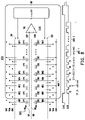
- FIG. 7 is a schematic diagram of capacitor calibration according to an embodiment of the disclosure.
- FIG. 8 is a schematic diagram of capacitor calibration according to an embodiment of the disclosure.
- FIG. 9A is a schematic diagram of a variation of a circuit block according to an embodiment of the disclosure.
- FIG. 9B is a schematic diagram of a variation of a circuit block according to an embodiment of the disclosure.
- FIG. 10A and FIG. 10B are schematic diagrams of clock signal reduction according to an embodiment of the disclosure.
- FIG. 11 is a flowchart of a calibration method of an SAR ADC according to the disclosure.
- FIG. 12 is a flowchart of a calibration method of an SAR ADC according to an embodiment of the disclosure.
- FIG. 13 is a flowchart of a calibration method of an SAR ADC according to an embodiment of the disclosure.
- An embodiment of the disclosure provides a calibration technology of a successive approximation register analog-to-digital converter (SAR ADC) based on a window switching architecture, which can effectively reduce the element size of a digital-to-analog converter (DAC) for the process limitations and the requirement to achieve higher linearity performance, and can also further reduce the dynamic power consumed due to the switching of the analog-to-digital converter (ADC).
- SAR ADC successive approximation register analog-to-digital converter
- ADC analog-to-digital converter
- the technology combines the advantages of window switching without adding other circuits to the signal path to obtain calibrated comparator offset and flicker noise information which may influence the calibration, and may also improve the capacitor weight deviation accumulated due to calibration, so as to further improve the integral nonlinearity (INL) of the ADC.
- FIG. 1 is a circuit block diagram of an SAR ADC 100 according to an embodiment of the disclosure.
- the SAR ADC 100 is configured to convert a first analog input signal VIP to a digital output signal SDO.
- the SAR ADC 100 may include a first capacitor digital-to-analog converter (CDAC) 120 , a comparator 140 , and a controller 160 .
- the first CDAC 120 may include a sampling switch 121 and switching capacitor sets SCP 1 to SCP 10 , which are respectively controlled by first control signals SP 1 to SP 10 .
- the first CDAC 120 may receive and sample the first analog input signal VIP through the sampling switch 121 at a time point to generate a first voltage VP 0 .
- the sampling switch 121 may be, for example, a bootstrapped switch controlled by a sampling clock signal CLKS.
- the first CDAC 120 is controlled by multiple first control signals SP 1 to SP 10 to respectively control the switching operation of the switching capacitor sets SCP 1 to SCP 10 .
- First terminals of capacitors CP 1 to CP 10 are coupled to a non-inverting input terminal of the comparator 140 , and second terminals of the capacitors CP 1 to CP 10 are switched between a reference voltage Vref and a ground voltage GND respectively through corresponding switches WP 1 to WP 10 .
- the switches WP 1 to WP 10 are respectively controlled by the first control signals SP 1 to SP 10 .
- Capacitance values of the capacitor CP 1 to the capacitor CP 8 are respectively twice capacitance values of the capacitor CP 2 to the capacitor CP 9 , and the capacitance value of the capacitor CP 9 is equal to the capacitance value of the capacitor CP 10 .
- “coupling” may be a direct connection or an indirect connection.
- the indirect connection is, for example, a connection through another element. For example, if it is stated that an element A is coupled to an element B, the element A may be directly connected to the element B, or the element A may be connected to the element B through an element C. For example, the element A is directly connected to the element C, and the element C is then directly connected to the element B.
- the comparator 140 receives the first voltage VP 0 from the first CDAC 120 and is controlled by a comparator clock signal CLKC to compare the first voltage VP 0 with a comparison reference voltage Vr, so as to generate a first comparison result CQ 1 .
- the comparison reference voltage Vr may be, for example, the reference voltage Vref.
- the controller 160 is coupled to the comparator 140 and the first CDAC 120 . In particular, the controller 160 may generate the first control signals SP 1 to SP 10 based on the first comparison result CQ 1 to respectively control the switching operation of the switching capacitor sets SCP 1 to SCP 10 .
- the controller 160 has binary window function.
- the controller 160 may determine the switching operation of at least one of the switching capacitor sets SCP 1 to SCP 10 based on the output of the comparator 140 , so as to approximate the output of the first CDAC 120 to the binary window.
- the binary window is an M-bit window, where M is a positive integer less than or equal to N.
- the controller 160 may switch (for example, switch from a first state to a second state) the k-th switching capacitor set SCPk among the switching capacitor sets SCP 1 to SCP 10 , so that the first CDAC 120 generates a corresponding second voltage VPk.
- the comparator 140 may compare the second voltage VPk of the k-th iteration operation with the comparison reference voltage Vr to generate a corresponding second comparison result CQ 2 _ k .
- the controller 160 may define (or determine) a window region WINk based on the first comparison result CQ 1 and the second comparison result CQ 2 _ k .
- the controller 160 may determine whether to switch the k-th switching capacitor set SCPk back to the first state or maintain the second state based on the first comparison result CQ 1 and the second comparison result CQ 2 _ k.
- the controller 160 maintains the k-th switching capacitor set in the second state (that is, the state after switching).
- the controller 160 maintains the k-th switching capacitor set in the second state (that is, the state after switching).
- the controller 160 switches the k-th switching capacitor set back to the first state (that is, the state before switching).
- FIG. 2 is a schematic diagram of a switching mechanism of a single-ended input SAR ADC when performing the binary window function according to an embodiment of the disclosure.
- the horizontal axis is the time and the vertical axis is the output voltage of the first CDAC 120 .
- M 4.
- the first CDAC 120 receives and samples the first analog input signal VIP through the sampling switch 121 to generate the first voltage VP 0 .
- the amplitude of the first analog input signal VIP is, for example, equal to the reference voltage Vref
- the common mode voltage of the first analog input signal VIP is, for example, equal to the reference voltage Vref.
- the comparator 140 may judge whether the first voltage VP 0 is greater than the comparison reference voltage Vr, thereby generating the first comparison result CQ 1 . Then, in the first iteration operation (i.e.
- the controller 160 may generate a first control signal SP 1 based on the first comparison result CQ 1 to control the switching operation of the switching capacitor set SCP 1 .
- the comparator 140 outputs the second comparison result CQ 2 _ 2 , for example, logic 0. If the second voltage VP 2 is less than the reference voltage Vr, it indicates that the second voltage VP 1 is less than 1.25Vref and is located within the window region WIN 2 .
- the comparator 140 outputs the second comparison result CQ 2 _ 2 , for example, logic 0. If the second voltage VP 2 is less than the reference voltage Vr, it indicates that the second voltage VP 1 is less than 0.75Vref and is located outside the window region WIN 2 .
- FIG. 3 is a circuit block diagram of an SAR ADC 200 according to another embodiment of the disclosure.
- the SAR ADC 200 is a differential input ADC.
- the SAR ADC 200 is configured to convert a differential pair signal (including the first analog input signal VIP and a second analog input signal VIN) to a digital output signal SDO.
- the SAR ADC 200 may include a first CDAC 220 , a second CDAC 280 , a comparator 240 , and a controller 260 .
- the architectures of the first CDAC 220 , the comparator 240 , and the controller 260 are respectively similar to the first CDAC 120 , the comparator 140 , and the controller 160 of FIG. 1 , which may be analogized by referring to the relevant descriptions of FIG. 1 , so there will be no reiteration here.
- the second CDAC 280 may include a sampling switch 281 and switching capacitor sets SCN 1 to SCN 10 .
- the second CDAC 280 may receive and sample the second analog input signal VIN through the sampling switch 281 at a time point to generate a third voltage VN 0 .
- the sampling switch 281 may be, for example, a bootstrapped switch controlled by a sampling clock signal CLKS.
- the second CDAC 280 is controlled by multiple second control signals SN 1 to SN 10 to respectively control the switching operation of the switching capacitor sets SCN 1 to SCN 10 .
- a switching capacitor set SCNi may include a capacitor CNi and a switch WNi, where i is an integer from 1 to 10.
- First terminals of the capacitors CN 1 to CN 10 are coupled to an inverting input terminal of the comparator 240 , and second terminals of the capacitors CN 1 to CN 10 are switched between the reference voltage Vref and the ground voltage GND through the switches WN 1 to WN 10 respectively.
- the switches WN 1 to WN 10 are respectively controlled by the second control signals SN 1 to SN 10 .
- Capacitance values of the capacitor CN 1 to the capacitor CN 8 are respectively twice capacitance values of the capacitor CN 2 to the capacitor CN 9 , and the capacitance value of the capacitor CN 9 is equal to the capacitance value of the capacitor CN 10 .
- the comparator 240 receives the first voltage VP 0 from the first CDAC 220 and the third voltage VN 0 from the second CDAC 280 .
- the comparator 240 may be controlled by the comparator clock signal CLKC to compare the difference between the first voltage VP 0 and the third voltage VN 0 with a zero crossing point, so as to generate the first comparison result CQ 1 .
- the controller 260 may generate the first control signals SP 1 to SP 10 and the second control signals SN 1 to SN 10 based on the first comparison result CQ 1 to respectively control the switching operation of the switching capacitor sets SCP 1 to SCP 10 and SCN 1 to SCN 10 .
- the controller 260 has binary window function.
- the controller 260 may, based on the output (that is, the first comparison result CQ 1 ) of the comparator 240 , determine the switching operation of at least one of the switching capacitor sets SCP 1 to SCP 10 and at least one of the switching capacitor sets SCN 1 to SCN 10 to approximate the output of the first CDAC 220 and the output of the second CDAC 280 to the binary window.
- the binary window is an M-bit window, where M is a positive integer less than or equal to N.
- the controller 260 may switch (for example, switch from the first state to the second state) the k-th switching capacitor set SCPk among the switching capacitor sets SCP 1 to SCP 10 , so that the first CDAC 220 generates the corresponding second voltage VPk.
- the controller 260 may switch (for example, switch from the first state to the second state) the k-th switching capacitor set SCNk among the switching capacitor sets SCN 1 to SCN 10 , so that the second CDAC 280 generates a corresponding fourth voltage VNk.
- the comparator 240 may compare the difference between the second voltage VPk and the fourth voltage VNk of the k-th iteration operation with the zero crossing point (for example, 0 volt) to generate a corresponding second comparison result CQ 2 _ k .
- the controller 260 may define (or determine) the window region WINk based on the first comparison result CQ 1 and the second comparison result CQ 2 _ k .
- controller 260 may, based on the first comparison result CQ 1 and the second comparison result CQ 2 _ k , determine whether to switch the k-th switching capacitor set of the first CDAC 220 and the k-th switching capacitor set of the second CDAC 280 back to the first state (that is, the state before switching) or maintain the second state.
- FIG. 4 is a schematic diagram of a switching mechanism of a differential input SAR ADC when performing the binary window function according to an embodiment of the disclosure.
- the horizontal axis is the time and the vertical axis is the voltage difference between the output voltage of the first CDAC 220 and the output voltage of the second CDAC 280 (that is, the differential input voltage of the comparator 240 ).
- M is other positive integers may be analogized based on the following descriptions.
- the first CDAC 220 controls a sampling switch 221 to receive and sample the first analog input signal VIP through the sampling clock signal CLKS, so as to generate the first voltage VP 0 .
- the second CDAC 280 controls a sampling switch 281 to receive and sample the second analog input signal VIN through the clock signal CLKS, so as to generate the third voltage VN 0 .
- the amplitudes of the first analog input signal VIP and the second analog input signal VIN are, for example, both equal to the reference voltage Vref, and the common mode voltages of the first analog input signal VIP and the second analog input signal VIN are, for example, equal.
- the phase difference between the first analog input signal VIP and the second analog input signal VIN is, for example, 180 degrees.
- the comparator 240 is controlled by the comparator clock signal CLKC to judge whether the difference between the first voltage VP 0 and the third voltage VN 0 is greater than the zero crossing point, thereby generating the first comparison result CQ 1 .
- the controller 260 may generate the first control signal SP 1 and a second control signal SN 1 based on the first comparison result CQ 1 to control the switching operations of the switching capacitor sets SCP 1 and SCN 1 .
- the following is illustrated with the difference between the first voltage VP 0 and the third voltage VN 0 greater than the zero crossing point (i.e. VP 0 ⁇ VN 0 >0).
- the controller 260 maintains the switch WP 1 of the switching capacitor set SCP 1 and the switch WN 1 of the switching capacitor set SCN 1 in the state after switching.
- the comparator 240 may compare the second voltage VP 2 with the fourth voltage VN 2 of the second iteration operation (i.e.
- the comparator 240 outputs the second comparison result CQ 2 _ 2 , for example, logic 1. If the difference between the second voltage VP 2 and the fourth voltage VN 2 is greater than the zero crossing point, it indicates that the difference between the second voltage VP 1 and the fourth voltage VN 1 is greater than 0.5Vref and is located outside the window region WIN 2 .
- the comparator 240 outputs the second comparison result CQ 2 _ 2 , for example, logic 0.
- the controller controls the switching operations of the first CDAC 220 and the second CDAC 280 based on the first comparison result CQ 1 and the second comparison result CQ 2 _ k .
- the controller 260 controls the switching operations of the first CDAC 220 and the second CDAC 280 based on the first comparison result CQ 1 and the second comparison result CQ 2 _ k .
- the detailed operations may be analogized by referring to the above descriptions, so there will be no reiteration.
- the ADC performs normal operation of analog-to-digital conversion in the operation mode and performs calibration in the calibration mode.
- the calibration mode before the operation mode is performed, the calibration mode may be performed first.
- the calibration mode may be performed after performing the operation mode for a period of time.
- the calibration mode may be (periodically) performed each time after performing the operation mode for a period of time.
- Capacitors CP 1 to CP 5 and CN 1 to CN 5 are capacitors to be calibrated, and capacitors CP 6 to CP 11 and CN 6 to CN 11 are accurate capacitors.
- each capacitor may include a group of capacitors.
- the capacitors CP 1 and CN 1 may each include 8 smaller capacitors, and the capacitors CP 2 and CN 2 may each include 4 smaller capacitors, which are not limited by the disclosure.
- the required accuracy may be achieved through required process parameters.
- the accurate capacitors are used as references to calibrate the less accurate capacitors.
- the accurate capacitors CP 6 to CP 11 and CN 6 to CN 11 are used to calibrate the less accurate capacitors CP 1 to CP 5 and CN 1 to CN 5 .
- FIG. 5 is a timing diagram of calibration according to an embodiment of the disclosure.
- the calibration process may be performed multiple times, and the calibration value becomes more accurate due to the multiple calibrations of the flicker noise and the comparator offset and the average value of the capacitors C 1 to C 5 .
- the calibration sequence in each calibration cycle is to first calibrate the flicker noise and the comparator offset (i.e. O & F in the drawing, which are both referred to as noise), and then calibrate the capacitors CP 5 to CP 1 and CN 5 to CN 1 .
- the flicker noise and the comparator offset are calibrated in the first cycle of a sampling clock CLKS, and the capacitors CP 5 to CP 1 and CN 5 to CN 1 are respectively calibrated in the second cycle to the sixth cycle of the sampling clock CLKS.
- Information Do[x] of the comparator offset and the flicker noise are obtained in the first cycle of the sampling clock CLKS, and the capacitors CP 5 to CP 1 and CN 5 to CN 1 are then calibrated in sequence at each sampling clock CLKS to respectively obtain calibration information Do[x+1] to Do[x+5].
- Do[x] is a binary digital code output by the ADC, where x represents each calibration cycle and is a positive integer, and y represents the number of repetitions of a calibration procedure and is a natural number. Similarly, the calibration procedure is continuously repeated. For example, calibration information Do[x+6] to Do[x+11] of the comparator offset and the flicker noise and the capacitors CP 5 to CP 1 and CN 5 to CN 1 may be obtained in the seventh to the twelfth cycle of the sampling clock CLKS. By analogy, the overall calibration procedure will continue for several cycles for averaging.
- the calibration method is explained together with the circuit structure.
- the calibration of the flicker noise and the comparator offset, the capacitors CP 5 and CN 5 , and the capacitors CP 1 and CN 1 will be used for explanation.
- the calibration method of the capacitors CP 4 and CN 4 to the capacitors CP 2 and CN 2 is similar to the calibration method of the capacitors CP 5 and CP 1 and the capacitors CN 5 and CN 1 .
- FIG. 6 to FIG. 8 illustrate the capacitor calibration method according to embodiments of the disclosure.
- FIG. 6 is a schematic diagram of calibration of flicker noise and offset of a comparator 340 according to an embodiment of the disclosure.
- an SAR ADC converter 300 may include a first CDAC 310 , a second CDAC 320 , the comparator 340 , and a controller 360 .
- Outputs VCP and VCN of the first CDAC 310 and the second CDAC 320 are respectively connected to two input terminals of the comparator 340 .
- Capacitors CP 1 and CN 1 correspond to the MSB, and the following are capacitors CP 2 and CN 2 , capacitors CP 3 and CN 4 , . . . in sequence, but the disclosure is not limited thereto.
- the comparison result output by the comparator 340 is then sent to the controller 360 .
- the controller 360 performs the control of the analog-to-digital conversion described in FIG. 1 to FIG. 4 , and/or performs the control such as capacitor calibration and quantization of the flicker noise and the offset of the comparator 360 .
- the flicker noise and the offset of the comparator 340 are calibrated.
- the sampling clock CLKS is at high voltage
- connect switches SW TOP1 and SW TOP2 of first terminals (or top plate) of the capacitors CP 1 to CP 11 and CN 1 to CN 11 are connected.
- the first terminals of the capacitors CP 1 to CP 11 of the first CDAC 310 are all connected to the first input voltage VIP via the switch SW TOP1
- the first terminals of the capacitors CN 1 to CN 11 of the second CDAC 320 are all connected to the second input voltage VIN via the switch SW TOP2 .
- the voltages of the first input voltage VIP and the second input voltage VIN are arbitrary voltage values, and the arbitrary voltage values are determined based on an input common mode voltage Vicm of the comparator.
- the voltage values of the first input voltage VIP and the second input voltage VIN are the input common mode voltage Vicm, and second terminals (or bottom plate) of the capacitors CP 1 to CP 11 and CN 1 to CN 11 are respectively switched to a first reference voltage Vcm by the switches WP 1 to WP 11 and WN 1 to WN 11 , so as to reset all the capacitors CP 1 to CP 11 and CN 1 to CN 11 .
- the voltage of the first input voltage VIP and the second input voltage VIN is Vcm
- the second terminals of the capacitors CP 1 to CP 11 and the capacitors CN 1 to CN 11 are switched to the input common mode voltage Vicm or other voltages by the switches WP 1 to WP 11 and the switches WN 1 to WN 11 , so as to reset all the capacitors CP 1 to CP 11 and CN 1 to CN 11 .
- the input common mode voltage Vicm of the operation mode is (VIP+VIN)/2.
- the first reference voltage Vcm may be the input common mode voltage Vicm.
- the voltages of the first terminals and the second terminals of the capacitors CP 1 to CP 11 and the capacitors CN 1 to CN 11 may be the same.
- the controller 360 disconnects the switches SW TOP1 and SW TOP2 , so that the first terminals of the capacitors CP 1 to CP 11 and the capacitors CN 1 to CN 11 are disconnected from the first input voltage VIP and the second input voltage VIN, and all the second terminals of the capacitors CP 1 to CP 5 and the capacitors CN 1 to CN 5 (that is, the capacitors to be calibrated) are maintained at the first reference voltage Vcm respectively by the switches WP 1 to WP 5 and the switches WN 1 to WN 5 .
- the calibration procedure is performed. In a cycle T 0 of the comparator clock CLKC, calibration of offset and flicker noise begin.
- the switches WP 1 to WP 5 of the capacitors CP 1 to CP 5 and the switches WN 1 to WN 5 of the capacitors CN 1 to CN 5 are not switched.
- the accurate capacitors CP 6 to CP 11 of the first CDAC 310 and the accurate capacitors CN 6 to CN 11 of the second CDAC 320 perform the digital-to-analog conversion of the SAR ADC 300 .
- zADC is a corresponding ADC including the accurate capacitors and/or calibrated capacitors. The switching of the corresponding capacitor is determined by the result of each bit of the zADC 5 , that is, performing the binary search method of the SAR ADC 300 .
- the capacitor of the VCP side of the bit is switched from the Vcm to the GND by the switch of the second terminal, and the capacitor of the VCN side is switched from the first reference voltage Vcm to the second reference voltage Vref by the switch of the second terminal.
- the result of the comparator 340 of the one bit is 0, it represents that the capacitor of the VCP side of the bit is switched from the first reference voltage Vcm to the second reference voltage Vref by the switch of the second terminal, and the capacitor of the VCN side is switched from the first reference voltage Vcm to the third reference voltage GND by the switch of the second terminal. In this way, after switching, the next bit is compared until all bits are converted.
- the binary output of seven digital bits obtained by the zADC 5 is the information of the flicker noise and the offset of the comparator 340 .
- all accurate capacitors are used to measure the information of the flicker noise and the offset of the comparator 340 , but the disclosure is not limited thereto.
- some of the accurate capacitors may be used to measure the information of the flicker noise and the offset of the comparator 340 .
- the information of the flicker noise and the offset of the comparator 340 may be measured using the corresponding ADC of several capacitors of lower bits including the LSB.
- CP 7 to CP 11 and CN 7 to CN 11 may be used for measurement, and the measurement method is similar to the above.
- the calibration procedure is performed.
- the cycle T 0 of the comparator clock CLKC the calibration of the offset and the flicker noise begin.
- the switches WP 1 to WP 6 of the capacitors CP 1 to CP 6 and the switches WN 1 to WN 6 of the capacitors CN 1 to CN 6 are not switched.
- the accurate capacitors CP 7 to CP 11 of the first CDAC 310 and the accurate capacitors CN 7 to CN 11 of the second CDAC 320 performs the digital-to-analog conversion of the SAR ADC 300 .
- the second terminals of the capacitors CP 7 to CP 11 and the capacitors CN 7 to CN 11 do not need to be connected to the first reference voltage Vcm and may be connected to the second reference voltage Vref or the third reference voltage GND based on the operation of the SAR ADC 300 .
- the obtained binary output of six digital bits is the information of the flicker noise and the offset of the comparator 340 .
- the high voltage and the low voltages in this embodiment are for illustration only.
- the capacitor reset may also be performed when the sampling clock CLKS is at low voltage, and the calibration may be performed when the sampling clock CLKS is at high voltage, which are not limited by the disclosure.
- the calibration procedure of the capacitors CP 1 to CP 5 and the capacitors CN 1 to CN 5 of the first CDAC 310 and the second CDAC 320 is performed.
- the capacitor calibration begins from the capacitor with the smallest bit among the capacitors to be calibrated.
- the capacitor calibration begins from the capacitor CP 5 and the capacitor CN 5 , that is, the capacitors whose bit ordering is closest to the accurate capacitors CP 6 to CP 11 and capacitors CN 6 to CN 11 .
- FIG. 7 is a schematic diagram of capacitor calibration according to an embodiment of the disclosure.
- the following embodiment illustrates the calibration of the capacitors CP 5 and CN 5 .
- the sampling clock CLKS is at the high voltage
- the first terminals of the capacitors CP 1 to CP 11 of the first CDAC 310 are all connected to the first input voltage VIP via the switch SW TOP1
- the first terminals of the capacitors CN 1 to CN 11 of the second CDAC 320 are all connected to the second input voltage VIN via the switch SW TOP2 .
- the voltages of the first input voltage VIP and the second input voltage VIN are the input common mode voltage Vicm, and the second terminals of the capacitors CP 1 to CP 11 and the capacitors CN 1 to CN 11 are switched to the Vcm by the switches WP 1 to WP 11 and WN 1 to WN 11 , so as to reset all the capacitors CP 1 to CP 11 and CN 1 to CN 11 .
- the corresponding second terminals of the capacitors CP 1 to CP 4 and the capacitors CN 1 to CN 4 of the first CDAC 310 and the second CDAC 320 are all maintained at the first reference voltage Vcm respectively via the switches WP 1 to WP 4 and the switches WN 1 to WN 4 , and the SW TOP1 and SW TOP2 are disconnected respectively from corresponding to the first CDAC 310 and the second CDAC 320 .
- the comparator 340 may perform the comparison, but does not switch the voltages of the second terminals of the capacitors.
- the switching control signal generated by the controller 360 may be blocked through the logic circuits inside the controller 360 , so that the switches WP 1 to WP 4 of the capacitors CP 1 to CP 4 and the switches WN 1 to WN 4 of the capacitors CN 1 to CN 4 are not switched during the period T 1 to T 4 .
- the calibration of the capacitors CP 5 and CN 5 begins.
- the second terminal of the capacitor CP 5 of the first CDAC 310 is connected to the second reference voltage Vref (reference voltage) through the switch WP 5
- the second terminal of the capacitor CN 5 of the second CDAC 320 is connected to the third reference voltage GND (ground voltage) through the switch WN 5 .
- the zADC 5 corresponding to the capacitors CP 6 to CP 11 and CN 6 to CN 11 performs the analog-to-digital conversion.
- the capacitors CP 6 to CP 11 of the first CDAC 310 and the capacitors CN 6 to CN 11 of the second CDAC 320 may be accurately manufactured through requesting process parameters. Therefore, an accurate result may be obtained by the zADC 5 corresponding to the CP 6 to CP 11 and the CN 6 to CN 11 performing the analog-to-digital conversion to calibrate the capacitors CP 5 and CN 5 .
- the result obtained by the analog-to-digital conversion performed by the zADC 5 contains the flicker noise and the offset of the comparator 340 .
- the result obtained by the analog-to-digital conversion performed by the zADC 5 is deducted by the flicker noise and the offset of the comparator 340 (for example, the flicker noise and the offset of the comparator 340 obtained above) to obtain a capacitor weight W C5 of the capacitor CP 5 and/or the capacitor CN 5 .
- the capacitor weight W C5 is the weight of the bit corresponding to the capacitor CP 5 and the capacitor CN 5 .
- the capacitor weight W C5 is the weight of the bits corresponding to the capacitor CP 5 .
- the capacitor weight W C5 is the weight of the bits corresponding to the capacitor CN 5 .
- Capacitor weights W C1 to W C4 are similar to the capacitor weight W C5 and may be analogized.
- FIG. 8 is a schematic diagram of capacitor calibration according to an embodiment of the disclosure.
- the following embodiment illustrates the calibration of the capacitors CP 1 and CN 1 .
- the sampling clock CLKS is at the high voltage
- the first terminals of the capacitors CP 1 to CP 11 of the first CDAC 310 are all connected to the first input voltage VIP via the switch SW TOP1
- the first terminals of the capacitors CN 1 to CN 11 of the second CDAC 320 are all connected to the second input voltage VIN via the switch SW TOP2 .
- the voltages of the first input voltage VIP and the second input voltage VIN are the input common mode voltage Vicm, and the second terminals of the capacitors CP 1 to CP 11 and the capacitors CN 1 to CN 11 are switched to the Vcm respectively by the switches WP 1 to WP 11 and the switches WN 1 to WN 11 , so as to reset all the capacitors CP 1 to CP 11 and CN 1 to CN 11 .
- the comparator 340 may perform the comparison, but does not switch the voltages of the second terminals of the capacitors.
- the calibration of the capacitors CP 1 and CN 1 is performed.
- the second terminal of the capacitor CP 1 of the first CDAC 310 is connected to the second reference voltage Vref (reference voltage) through the switch WP 1
- the second terminal of the capacitor CN 1 of the second CDAC 320 is connected to the third reference voltage GND (ground voltage) through the switch WN 1 .
- the analog-to-digital conversion is performed using a zADC 1 (including the SAR ADC corresponding to the calibrated capacitors CP 2 to CP 5 and CN 2 to CN 5 and the accurate capacitors CP 6 to CP 11 and CN 6 to CP 11 ).
- the voltage of the second terminal of the capacitor corresponding to each bit is switched according to the comparison result of each bit of the zADC 1 .
- the obtained binary output of eleven digital bits is the weights of the capacitors CP 1 and CN 1 .
- the result obtained by the zADC 1 performing the analog-to-digital conversion contains the flicker noise and the offset of the comparator 340 .
- the weights of the capacitors CP 1 and CN 1 obtained by the zADC 1 performing the analog-to-digital conversion is deducted by the flicker noise and the offset of the comparator 340 (for example, the flicker noise and the offset of the comparator 340 obtained above) to obtain the capacitor weight W C1 of the capacitors CP 1 and CN 1 .
- the capacitors CP 6 to CP 11 of the first CDAC 310 and the capacitors CN 6 to CN 11 of the second CDAC 320 are accurate capacitors, and the capacitors CP 2 to CP 5 and CN 2 to CN 5 have also been calibrated.
- the capacitors CP 2 to CP 11 and CN 2 to CN 11 of the zADC 1 perform general successive approximation analog-to-digital conversion, the capacitors CP 1 and CN 1 may be calibrated.
- the weight of the capacitors CP 1 and CN 1 obtained contains the flicker noise and the offset of the comparator 340 , so the flicker noise and the offset of the comparator 340 may be deducted to obtain the capacitor weight W C1 of the capacitors CP 1 and CN 1 .
- the capacitor weights of the capacitors CP 2 to CP 4 of the first CDAC 310 and the capacitors CN 2 to CN 4 of the second CDAC 320 may be calibrated. Taking the calibration of the capacitors CP 4 and CN 4 as an example, when the sampling clock CLKS is at the high voltage, the capacitors CP 1 to CP 11 and CN 1 to CN 11 are reset. When the sampling clock CLKS is at the low voltage and during the cycles T 0 to T 3 of the comparator clock CLKC, the SW TOP1 and SW TOP2 are disconnected.
- the second terminals of the capacitors CP 1 to CP 3 and CN 1 to CN 3 are maintained at the first reference voltage Vcm, the second terminal of the capacitor CP 4 of the first CDAC 310 is switched to the second reference voltage Vref through the switch WP 4 , and the second terminal of the capacitor CN 4 of the second CDAC 320 is switched to the third reference voltage GND through the switch WN 4 .
- the capacitors CP 4 and CN 4 begin to be calibrated.
- the general successive approximation analog-to-digital conversion is performed using a zADC 4 (containing the SAR ADC corresponding to the calibrated capacitors CP 5 and CN 5 and the accurate capacitors CP 6 to CP 11 and CN 6 to CN 11 ).
- the flicker noise and the offset of the comparator 340 are then deducted to obtain the capacitor weight W C4 of the capacitors CP 4 and CN 4 .
- the calibration method of the capacitors CP 2 and CN 2 , and CP 3 and CN 3 is similar to the above and may be analogized.
- the timing of the calibration procedure of the SAR ADC 300 in the calibration mode is the same as or similar to the timing in the operation mode, so there is no need to add or change the circuit to achieve the calibration of capacitors and the measurements of the flicker noise and the offset of the comparator 340 .
- the capacitor weights may be used to correct the digital codes output by the first CDAC 310 and/or the second CDAC 320 , so as to obtain the accurate digital codes.
- the digital codes output by the first CDAC 310 and/or the second CDAC 320 may deviate from the correct digital codes.
- a redundant circuit (not shown) may be used to correct the deviation, so as to obtain the correct digital codes.
- the flicker noise and the offset of the comparator 340 may be quantified.
- another embodiment is used to illustrate the calculation manner of the capacitor weights W C1 to W C5 of the capacitors CP 1 to CP 5 and the capacitors CN 1 to CN 5 .
- one of the calibration procedures is to use 6 cycles of the sampling clock CLKS.
- the calibration of the flicker noise, the comparator offset, and the capacitors CP 5 to CP 1 and the capacitors CN 5 to CN 1 is respectively performed during the six cycles.
- the calibration procedure may be executed multiple times, and the calibration values obtained each time are averaged to obtain more accurate capacitor calibration values. As shown in FIG.
- average weights W C1avg to W C5avg of the capacitors CP 5 to CP 1 and CN 5 to CN 1 may be obtained by calculating Equation (1).
- W C1avg is the average weight of the capacitors CP 1 and CN 1
- D 0 [x+6y] is the flicker noise and the offset of the comparator 340 obtained at the (y+1)-th time, where x represents each calibration cycle and is a positive integer, and y represents the number of repetitions of a calibration procedure and is a natural number.
- D0[(x+1)+6y] to D0[(x+5)+6y], D0[x+6y], etc. are the binary digital codes obtained by the operation of the SAR ADC 300 in each calibration cycle.
- FIG. 9A is a schematic diagram of a variation of a circuit block according to an embodiment of the disclosure.
- the SAR ADC 300 may further include an encoder 380 , coupled to the controller 360 and configured to receive the output of the controller 360 ; and a calibration processor 400 , coupled to the encoder 380 .
- the SAR ADC 300 outputs a binary digital result to the encoder 380 , the encoder 380 encodes the binary digital result to generate a decimal encoding result, and the encoding result is then sent to the calibration processor 400 .
- the calibration processor 400 may use a loop to average the calibration procedures performed y times.
- the calculation of Equation (1) may be performed by the calibration processor 400 .
- the averaged capacitor weights W C1avg to W C5avg may be used to correct the digital codes output by the first CDAC 310 and/or the second CDAC 320 .
- the analog-to-digital conversion is performed in the operation mode to obtain an accurate result of the analog-to-digital conversion.
- by averaging data obtained from multiple calibrations the influence of white noise may be eliminated.
- an unaveraged single capacitor weight W C1 to W C5 may be used to correct the digital codes output by the first CDAC 310 and/or the second CDAC 320 .
- FIG. 9B is a schematic diagram of a variation of a circuit block according to an embodiment of the disclosure.
- the SAR ADC 300 may further include a clock reduction circuit 345 , which may be configured to generate a reduced comparator clock RCLKC.
- the clock reduction circuit 345 may reduce the comparator clock CLKC to generate the reduced comparator clock RCLKC.
- the reduced comparator clock RCLKC may be used to further reduce the calibration time.
- the calibration begins with the capacitor to be calibrated closest to the LSB and ends with the capacitor to be calibrated closest to the MSB.
- the calibration of the capacitors CP 1 to CP 5 and CN 1 to CN 5 begins with the capacitors CP 5 and CN 5 , and the capacitors CP 1 and CN 1 are then calibrated in sequence.
- the first calibrated capacitors CP 5 and CN 5 are the capacitors to be calibrated closest to the LSB, and the capacitors CP 6 to CP 11 and CN 6 to CN 11 as the basis of the calibration are all accurate capacitors.
- the capacitors CP 5 to CP 11 and CN 5 to CN 11 are used to calibrate the next capacitors CP 4 and CN 4 to be calibrated that are closest to the LSB.
- the capacitor to be calibrated closest to the LSB is calibrated each time, and the capacitors used to calibrate the capacitor to be calibrated includes the previously calibrated capacitors and the accurate capacitors.
- the disclosure is not limited thereto.
- the calibration after measuring the noise, the calibration begins with the capacitor to be calibrated closest to the MSB and ends with the capacitor to be calibrated closest to the LSB.
- the descriptions of the calibration from the MSB side to the LSB side are as follows.
- the capacitors CP 2 to CP 11 and CN 2 to CN 11 are used to calibrate the capacitors CP 1 and CN 1 .
- the capacitors CP 6 to CP 11 and CN 6 to CN 11 in the zADC 1 are accurate, but the capacitors CP 2 to CP 5 and CN 2 to CN 5 have not been calibrated. Therefore, when weights W C1 ′ of the capacitors CP 1 and CN 1 are obtained using the above manner, the W C1 ′ may contain the errors of the capacitors CP 2 to CP 5 and CN 2 to CN 5 .
- weights W C2 ′ of the capacitors CP 2 and CN 2 may contain the errors of the capacitors CP 3 to CP 5 and CN 3 to CN 5
- a weight W C3 ′ of the capacitor CP 3 may contain the errors of the capacitors CP 4 to CP 5 and CN 4 to CN 5
- weights W C4 ′ of the capacitors CP 4 and CN 4 may contain the errors of the capacitors CP 5 and CN 5 .
- the capacitor weight W C5 of the capacitors CP 5 and CN 5 are used to calculate the correct capacitor weight W C4 of the capacitors CP 4 and CN 4
- the weights W C5 and W C4 of the capacitors CP 5 and CN 5 and the capacitors CP 4 and CN 4 are used to calculate the correct capacitor weight W C3 of the capacitors CP 3 and CN 3
- the weights W C5 to W C2 are finally used to calculate the correct capacitor weights W C1 of the capacitors CP 1 and CN 1 .
- the calculation manner of the average capacitor weights of the capacitors CP 1 to CP 5 and CN 1 to CN 5 may be obtained by calculating Equation (1).
- the calibration timing uses the clock timing of the SAR ADC in the operation mode. Therefore, it is possible to achieve the capacitor calibration and the measurements of the flicker noise and the offset of the comparator 340 without adding or changing the hardware structure of the circuit.
- the calibration time may be further reduced. For example, as shown in FIG. 7 , when the capacitors CP 5 and CN 5 are calibrated, the timing of the original operation mode is used. During the cycles T 0 to T 4 of the comparator clock CLKC, the capacitor is not switched. Therefore, the cycles T 0 to T 4 may be reduced to reduce the calibration time.
- FIG. 10A and FIG. 10B are schematic diagrams of clock signal reduction according to an embodiment of the disclosure.
- the cycle T 0 is the cycle of the sample-and-hold operation
- the cycles T 1 to T 5 are the corresponding analog-to-digital conversion cycles of the capacitors CP 1 to CP 5 and CN 1 to CN 5 .
- the capacitors CP 1 to CP 5 and CN 1 to CN 5 are not switched during the cycles T 1 to T 5 , and the analog-to-digital conversion of the zADC 5 is performed until the next cycle of the comparator clock CLKC.
- the cycles T 1 to T 5 are omitted in the calibration mode. That is, the operation of the zADC 5 is performed in the next cycle of the cycle T 0 , and the timing thereof is shown as the waveform of the reduced comparator clock RCLKC.
- the cycle T 0 is the cycle of the sample-and-hold operation
- the cycles T 1 to T 5 are the corresponding analog-to-digital conversion cycles of the capacitors CP 1 to CP 5 and CN 1 to CN 5 .
- the capacitors CP 1 to CP 4 and CN 1 to CP 4 are not switched during the cycles T 1 to T 4 .
- the voltages of the second terminals of the capacitors CP 5 and CN 5 are switched in the cycle T 5 , and the analog-to-digital conversion of the zADC 5 is then performed.
- the cycles T 0 to T 4 are omitted in the calibration mode.
- the first cycle of the comparator clock CLKC may be the cycle T 5 .
- the calibration procedures of the capacitors CP 5 and CN 5 are performed, and the timing thereof is shown as the waveform of the reduced comparator clock RCLKC.
- there is no need to wait for the cycles T 0 to T 4 so that the calibration time is faster.
- the waiting cycle of the cycles T 0 to T 3 may be omitted.
- the waiting cycle of the cycles T 0 to T 2 may be omitted.
- the waiting cycle of the cycles T 0 to T 1 may be omitted.
- the waiting cycle of the cycle T 0 may be omitted. In this way, the overall calibration time may be further shortened.
- the CDAC has Nd bits, where Nd is a positive integer.
- the reduced comparator clock RCLKC omits the waiting cycle of the (Nd ⁇ 1)-bit to the (i+1)-th bit capacitors in the operation mode timing (the comparator clock CLKC), where i is an integer less than Nd.
- the clock reduction circuit 345 may be added to the SAR ADC 300 and is configured to perform clock reduction, that is, to reduce the comparator clock CLKC of the operation mode to the reduced comparator clock RCLKC, which omits the waiting cycle.
- the voltage of the second terminal of the capacitor to be calibrated of the first CDAC 310 is switched to be connected to the second reference voltage Vref, and the second terminal of the capacitor to be calibrated of the second CDAC 320 is switched to be connected to the third reference voltage GND, but the disclosure is not limited thereto.
- the voltage of the second terminal of the capacitor to be calibrated of the first CDAC 310 is switched to be connected to the third reference voltage GND, and the second terminal of the capacitor to be calibrated of the second CDAC 320 is switched to be connected to the second reference voltage Vref.
- the voltage of the second terminal of the capacitor to be calibrated of the first CDAC 310 may be connected to the second reference voltage Vref or the third reference voltage GND, that is, may be switched to different reference voltages, and may also be switched to other voltages in another embodiment.
- the voltage of the second terminal of the capacitor to be calibrated of the second CDAC 320 may be connected to the second reference voltage Vref or the third reference voltage GND, that is, may be switched to different reference voltages, and may also be switched to other voltages in another embodiment.
- the second reference voltage may be one of the Vref or the GND
- the third reference voltage may be the other one of the Vref or the GND.
- the second reference voltage may be the GND
- the third reference voltage may be the Vref.
- a differential circuit (such as the circuit shown in FIG. 3 ) is used to illustrate the capacitor calibration procedure, but a single-ended circuit (such as the circuit shown in FIG. 1 ) may also be applied to the capacitor calibration method of the disclosure. That is, the input terminal of the comparator 340 being connected to only one CDAC may also be applied to the capacitor calibration method of the disclosure.
- the capacitor calibration method under the single-ended circuit architecture is the same or similar to the calibration method of the differential circuit, and the description thereof is omitted here.
- FIG. 11 is a flowchart of a calibration method of an SAR ADC according to the disclosure.
- the SAR ADC includes at least one Nd-bit CDAC.
- the capacitors of the CDAC correspond to the 0-th bit to the (Nd ⁇ 1)-th bit.
- the capacitor of the 0-th bit to the capacitor of the (i ⁇ 1)-th bit are, for example, the accurate capacitors (such as the capacitors CP 11 to CP 6 and CN 11 to CN 6 ), and the capacitor of the i-th bit to the capacitor of the (Nd ⁇ 1)-th bit are, for example, the capacitors to be calibrated (such as the capacitors CP 5 to CP 1 and CN 5 to CN 1 ), where i is an integer less than Nd.
- the digital code converted by the Nd-bit CDAC is converted by the SAR ADC to obtain digital codes of (Nd+1) bits.
- the SAR ADC does not need capacitor operation, and compares the difference between the VIP and the VIN to obtain the digital code of 1 more bit.
- the capacitors of the i-th bit to the (Nd ⁇ 1)-th bit are coupled to the first reference voltage, and a first digital code is generated based on the operation of the capacitors of the (i ⁇ 1)-th bit to the 0-th bit, where i is an integer less than Nd.
- the noise may be obtained in Step S 100 .
- the noise may include the flicker noise and the comparator offset.
- the first terminals of the capacitors of the (Nd ⁇ 1)-th bit to the 0-th bit are connected to the input voltage (such as the VIP and the VIN), and the second terminals of capacitors are connected to the first reference voltage (such as the Vcm).
- the first terminals of the capacitors of the (Nd ⁇ 1)-th bit to the 0-th bit are disconnected from the input voltage, and the first digital code is generated using the SAR ADC corresponding to the capacitors of the (i ⁇ 1)-th bit to the 0-th bit to measure the noise.
- Step S 102 is executed.
- the capacitors of the (i+1)-th bit to the (Nd ⁇ 1)-th bit are coupled to the first reference voltage
- the capacitor of the i-th bit is coupled to the second reference voltage
- a second digital code is generated based on the operation of the capacitors of the (i ⁇ 1)-th bit to the 0-th bit.
- the capacitor of the i-th bit is calibrated based on the operation of the capacitors of the (i ⁇ 1)-th bit to the 0-th bit
- the second digital code is generated by the comparator
- the second digital code is deducted by the first digital code to generate a weight of the capacitor of the i-th bit.
- the capacitor of the i-th bit is coupled to the second reference voltage or the third reference voltage, and the capacitors of the (Nd ⁇ 1)-th bit to the (i+1)-th bit are coupled to the first reference voltage.
- the second digital code is generated using the SAR ADC corresponding to the capacitors of the (i ⁇ 1)-th bit to the 0-th bit, and a weight of the capacitor of the i-th bit is generated based on the second digital code and the first digital code.
- the first terminals of the capacitors (such as the CP 1 to CP 11 and CN 1 to CN 11 ) of the (Nd ⁇ 1)-th bit to the 0-th bit are connected to the input voltage (such as the VIP and VIN), and the second terminals of capacitors are connected to the first reference voltage (such as the Vcm).
- the first terminals of the capacitors of the (Nd ⁇ 1)-th bit to the 0-th bit are disconnected from the input voltage.
- the second terminal of the capacitor of the i-th bit is coupled to the second reference voltage (such as the Vref) or the third reference voltage (such as the GND).
- the second digital code is generated using the SAR ADC corresponding to the capacitors of the (i ⁇ 1)-th bit to the 0-th bit, and the capacitor weight of the capacitor of the i-th bit is generated based on the second digital code and the first digital code.
- a step may be added between Steps S 102 and S 106 to generate the capacitor weight of the capacitor of the i-th bit based on the first digital code and the second digital code.
- the capacitor weight of the capacitor of each bit may be generated based on each second digital code obtained by performing Step S 102 each time. After obtaining the capacitor weight of each bit or the capacitor weights of all the bits, the corresponding SAR ADC may be corrected based on the obtained capacitor weight.
- FIG. 12 is a flowchart of a calibration method of an SAR ADC according to an embodiment of the disclosure.
- the SAR ADC includes at least one CDAC and a controller.
- the at least one CDAC includes Nd capacitors corresponding to Nd bits, where Nd is a positive integer.
- Nd is a positive integer.
- Step S 1202 the capacitors of the z-th bit to the (Nd ⁇ 1)-th bit are coupled to a first reference voltage, and a first digital code is generated based on the operation of the capacitors of the (z ⁇ 1)-th bit to the 0-th bit, where z is an integer less than Nd.
- the CDAC of the 0-th to the 5-th bits have accurate capacitors.
- Nd is, for example, 11 and z is, for example, 5.
- the capacitors of the 5-th bit to the 10-th bit are coupled to the first reference voltage, and the first digital code is generated based on the operation of the capacitors of the 4-th bit to the 0-th bit.
- the first digital code includes the flicker noise and the comparator offset.
- Step S 1204 the capacitors of the (i+1)-th bit to the (Nd ⁇ 1)-th bit are coupled to the first reference voltage, the capacitor of the i-th bit is coupled to a second reference voltage, and a second digital code is generated based on the operation of the capacitors of the (i ⁇ 1)-th bit to the 0-th bit, where i is an integer less than Nd, and z is less than i.
- i is, for example, 6.
- the capacitors of the 7-th bit to the 10-th bit are coupled to the first reference voltage, the capacitor of the 6-th bit is coupled to the second reference voltage, and the second digital code is generated based on the operation of the capacitors of the 5-th bit to the 0-th bit.
- Step S 1206 the capacitor weight of the capacitor of the i-th bit is generated based on the first digital code and the second digital code.
- the capacitor weight of the capacitor of the 6-th bit is generated using the first digital code generated by the operation of the capacitors of the 4-th bit to the 0-th bit and using the second digital code generated by the capacitors of the 5-th bit to the 0-th bit.
- the SAR ADC is calibrated based on the capacitor weight of the capacitor of the i-th bit.
- FIG. 13 is a flowchart of a calibration method of an SAR ADC according to an embodiment of the disclosure.
- the SAR ADC includes at least one CDAC and a controller.
- the at least one CDAC includes Nd capacitors corresponding to Nd bits, where Nd is a positive integer. As shown in FIG. 13 .
- Step S 1302 the capacitors of the i-th bit to the (Nd ⁇ 1)-th bit are coupled to a first reference voltage, and a first digital code is generated based on the operation of the capacitors of the (i ⁇ 1)-th bit to the 0-th bit, where i is an integer less than Nd.
- Nd is, for example, 11 and i is, for example, 6.
- the capacitors of the 6-th bit to the 10-th bit are coupled to the first reference voltage, and the first digital code is generated based on the operation of the capacitors of the 5-th bit to the 0-th bit.
- the first digital code includes the flicker noise and the comparator offset.
- Step S 1304 the capacitors of the (i+1)-th bit to the (Nd ⁇ 1)-th bit are coupled to the first reference voltage, the capacitor of the i-th bit is coupled to a second reference voltage, and a second digital code is generated based on the operation of the capacitors of the (i ⁇ 1)-th bit to the 0-th bit.
- i is, for example, 6.
- the capacitors of the 7-th bit to the 10-th bit are coupled to the first reference voltage, the capacitor of the 6-th bit is coupled to the second reference voltage, and the second digital code is generated based on the operation of the capacitors of the 5-th bit to the 0-th bit.
- the capacitor weight of the capacitor of the i-th bit is generated based on the first digital code and the second digital code.
- the capacitor weight of the capacitor of the 6-th bit is generated using the first digital code generated by the operation of the capacitors of the 5-th bit to the 0-th bit and using the second digital code generated by the capacitors of the 5-th bit to the 0-th bit.
- the SAR ADC is calibrated based on the capacitor weight of the capacitor of the i-th bit.
- the capacitor calibration method does not need to add an additional circuit architecture, and may be performed under the operation architecture of the original SAR ADC.
- the comparator clock CLKC that drives the SAR ADC for analog-to-digital conversion is used as the calibration clock.
- the capacitors CP 1 to CP 5 and CN 1 to CN 5 may be driven to perform the analog-to-digital conversion in the operation mode.
- the calibrated capacitors may be connected to the second reference voltage Vref or the third reference voltage GND, and the other uncalibrated capacitors are connected to the first reference voltage Vcm. Therefore, in an embodiment, the control sequence inside the controller 360 may be changed to adapt to the operation mode and the calibration mode without drastically changing the overall circuit architecture and also without increasing the capacitor area, so the size of the overall circuit will not become larger.
- the time required for calibration may be reduced to (NumC+1) cycles, which is about twice as fast as the 2NumC cycles required for traditional calibration. If the calibration process is repeated several times successively, the calibration process may also be used to eliminate the white noise generated by the circuit, so that the calibration is more accurate.
- the information of the flicker noise and the comparator offset may be obtained without adding a circuit to the signal path.
- an embodiment of the disclosure may improve the capacitor weight deviation accumulated due to calibration, so as to further improve the integral nonlinearity of the CDAC.
- a calibration method of an SAR ADC includes at least one CDAC and a controller.
- the CDAC includes Nd capacitors corresponding to Nd bits, where Nd is a positive integer.
- the capacitor calibration method of the SAR ADC includes the following steps. The capacitors of the z-th bit to the (Nd ⁇ 1)-th bit are coupled to a first reference voltage, and a first digital code is generated based on the operation of the capacitors of the (z ⁇ 1)-th bit to the 0-th bit, where z is an integer less than Nd.
- the capacitors of the (i+1)-th bit to the (Nd ⁇ 1)-th bit are coupled to the first reference voltage, the capacitor of the i-th bit is coupled to a second reference voltage, and a second digital code is generated based on the operation of the capacitors of the (i ⁇ 1)-th bit to the 0-th bit, where i is an integer less than Nd, and z is less than i.
- the capacitor weight of the capacitor of the i-th bit is generated based on the first digital code and the second digital code.
- the SAR ADC is calibrated based on the capacitor weight of the capacitor of the i-th bit.
- the step of coupling the capacitors of the z-th bit to the (Nd ⁇ 1)-th bit to the first reference voltage, and generating the first digital code based on the operation of the capacitors of the (z ⁇ 1)-th bit to the 0-th bit includes the following steps.
- the first terminals of the capacitors of the (Nd ⁇ 1)-th bit to the 0-th bit are coupled to an input voltage, and the second terminals of the capacitors of the (Nd ⁇ 1)-th bit to the 0-th bit are coupled to a first reference voltage.
- the first terminals of the capacitors of the (Nd ⁇ 1)-th bit to the 0-th bit are disconnected from the input voltage.
- the first digital code is generated using the SAR ADC corresponding to the capacitors of the (z ⁇ 1)-th bit to the 0-th bit.
- a calibration method of an SAR ADC includes at least one CDAC and a controller.
- the at least one CDAC includes Nd capacitors corresponding to Nd bits, where Nd is a positive integer.
- the capacitor calibration method of the SAR ADC includes the following steps. The capacitors of the i-th bit to the (Nd ⁇ 1)-th bit are coupled to a first reference voltage, and a first digital code is generated based on the operation of the capacitors of the (i ⁇ 1)-th bit to the 0-th bit, where i is an integer less than Nd.
- the capacitors of the (i+1)-th bit to the (Nd ⁇ 1)-th bit are coupled to the first reference voltage, the capacitor of the i-th bit is coupled to a second reference voltage, and a second digital code is generated based on the operation of the capacitors of the (i ⁇ 1)-th bit to the 0-th bit.
- the capacitor weight of the capacitor of the i-th bit is generated based on the first digital code and the second digital code.
- the SAR ADC is calibrated based on the capacitor weight of the capacitor of the i-th bit.
- the capacitor calibration method of the SAR ADC further includes the following step.
- the capacitor calibration method is performed multiple times to obtain the average value of the capacitor weights of the i-th bit.
- the step of coupling the capacitors of the i-th bit to the (Nd ⁇ 1)-th bit to the first reference voltage, and generating the first digital code based on the operation of the capacitors of the (i ⁇ 1)-th bit to the 0-th bit includes the following steps.
- the first terminals of the capacitors of the (Nd ⁇ 1)-th bit to the 0-th bit are coupled to an input voltage, and the second terminals of the capacitors of the (Nd ⁇ 1)-th bit to the 0-th bit are coupled to a first reference voltage.
- the first terminals of the capacitors of the (Nd ⁇ 1)-th bit to the 0-th bit are disconnected from the input voltage.
- the first digital code is generated using the SAR ADC corresponding to the capacitors of the (i ⁇ 1)-th bit to the 0-th bit.
- the step of coupling the capacitors of the (i+1)-th bit to the (Nd ⁇ 1)-th bit to the first reference voltage, coupling the capacitor of the i-th bit to the second reference voltage, and generating the second digital code based on the operation of the capacitors of the (i ⁇ 1)-th bit to the 0-th bit includes the following steps.
- the second terminals of the capacitors of the (i+1)-th bit the (Nd ⁇ 1)-th bit are coupled to the first reference voltage, and the second terminal of the capacitor of the i-th bit is coupled to the second reference voltage.
- the second digital code is generated using the SAR ADC corresponding to the capacitors of the (i ⁇ 1)-th bit to the 0-th bit.
- the at least one CDAC includes a first CDAC and a second CDAC.
- the step of coupling the second terminal of the capacitor of the i-th bit to the second reference voltage includes the following steps.
- the second terminal of the capacitor of the i-th bit of the first CDAC is coupled to the second reference voltage.
- the second terminal of the capacitor of the i-th bit of the second CDAC is coupled a third reference voltage.
- the SAR ADC further includes a comparator.
- the input voltage is determined by the input common mode voltage of the comparator.
- the capacitor calibration method of the SAR ADC further includes the following steps. After generating the second digital code, the capacitors of the (i+2)-th bit to the (Nd ⁇ 1)-th bit of are coupled to the first reference voltage, the capacitor of the (i+1)-th bit is coupled to the second reference voltage, and a third digital code is generated based on the operation of the capacitors of the i-th bit to the 0-th bit. The capacitor weight of the capacitor of the i-th bit is generated based on the first digital code and the third digital code. In an embodiment, i is repeatedly and progressively increased upward to generate the capacitor weight of each capacitor until the capacitor weight of the (Nd ⁇ 1)-th bit is generated.
- the capacitor calibration method of the SAR ADC further includes the following steps. After generating the second digital code, the capacitors of the i-th bit to the (Nd ⁇ 1)-th bit are coupled to the first reference voltage, the capacitor of the (i ⁇ 1)-th bit is coupled to the second reference voltage, and the third digital code is generated based on the operation of the capacitors of the (i ⁇ 2)-th bit to the 0-th bit. The capacitor weight of the capacitor of the (i ⁇ 1)-th bit is generated based on the first digital code and the third digital code. In an embodiment, i is repeatedly and progressively decreased downward to generate the capacitor weight of each capacitor until the capacitor weight of the (a+1)-th bit is generated.
- the capacitor calibration method of the SAR ADC further includes the following step.
- the capacitor weight of the capacitor of the j-th bit is obtained based on the capacitor weights of the capacitors of the (j ⁇ 1)-th bit to the i-th bit, where Nd>j>i.
- the calibration timing of the capacitor calibration method is the same as the operation mode timing of the SAR ADC.
- the calibration timing of the capacitor calibration method omits the waiting cycle of the capacitors of the (Nd ⁇ 1)-th bit to the (i+1)-th bit in the operation mode timing.
- the SAR ADC further includes a comparator, and the first digital code includes the information of the flicker noise and the comparator offset.
- the step of generating the capacitor weight of the capacitor of the i-th bit based on the first digital code and the second digital code includes the following step.
- the first digital code is deducted by the second digital code to generate the capacitor weight of the capacitor of the i-th bit.
- an SAR ADC with calibration function which includes at least one CDAC, controlled by multiple control signals to respectively control the switching operations of Nd switching capacitors of the at least one CDAC, where Nd is a positive integer; a comparator, coupled to the at least one CDAC and configured to compare the output of the at least one CDAC with a comparison voltage; and a controller, coupled to the comparator and the at least one CDAC, and configured to generate the control signal and a digital output signal based on the output of the comparator.
- the controller is in the calibration mode, the capacitor weight of the i-th bit of the at least one CDAC is obtained by the result of (Nd+1) operations of the comparator, where i is an integer less than Nd.
- the SAR ADC with calibration function when the controller is in the operation mode, the output of the at least one CDAC is approximated to the Nd-bit window based on the output of the comparator.
- An operation of approximating the output of the CDAC to the Nd-bit window is completed by the result of (Nd+1) comparison operations of the comparator.
- an SAR ADC with calibration function which includes at least one Nd-bit CDAC, having Nd capacitors, where Nd is a positive integer; and a controller, coupled to the at least one CDAC.
- the controller is configured to perform the following capacitor calibration procedure.
- the capacitors of the z-th bit to the (Nd ⁇ 1)-th bit are coupled to the first reference voltage, and a first digital code is generated based on the operation of the capacitors of the (z ⁇ 1)-th bit to the 0-th bit, where z is an integer less than Nd.
- the capacitors of the (i+1)-th bit to the (Nd ⁇ 1)-th bit are coupled to the first reference voltage, and the capacitor of the i-th bit is coupled to the second reference voltage, a and a second digital code is generated based on the operation of the capacitors of the (i ⁇ 1)-th bit to the 0-th bit, where i is an integer less than Nd, and z is less than i.
- the capacitor weight of the capacitor of the i-th bit is generated based on the first digital code and the second digital code.
- the SAR ADC is calibrated based on the capacitor weight of the capacitor of the i-th bit.
- an SAR ADC with calibration function which includes at least one Nd-bit CDAC, having Nd capacitors, where Nd is a positive integer; and a controller, coupled to the at least one CDAC.
- the controller is configured to perform the following capacitor calibration procedure.
- the capacitors of the i-th bit to the (Nd ⁇ 1)-th bit are coupled to a first reference voltage, a first digital code is generated based on the operation of the capacitors of the (i ⁇ 1)-th bit to the 0-th bit, where i is an integer less than Nd.
- the capacitors of the (i+1)-th bit to the (Nd ⁇ 1)-th bit are coupled to the first reference voltage, the capacitor of the i-th bit is coupled to a second reference voltage, and a second digital code is generated based on the operation of the capacitors of the (i ⁇ 1)-th bit to the 0-th bit.
- the capacitor weight of the capacitor of the i-th bit is generated based on the first digital code and the second digital code.
- the SAR ADC is calibrated based on the capacitor weight of the capacitor of the i-th bit.
- the controller further performs the calibration procedure more times to obtain the average value of the capacitor weight of the i-th bit.
- the controller when the controller performs the step of coupling the capacitors of the i-th bit to the (Nd ⁇ 1)-th bit to the first reference voltage, and generating the first digital code based on the operation of the capacitors of the (i ⁇ 1)-th bit to the 0-th bit, the first terminals of the capacitors of the (Nd ⁇ 1)-th bit to the 0-th bit are coupled to an input voltage, and the second terminals of the capacitors of the (Nd ⁇ 1)-th bit to the 0-th bit are coupled to the first reference voltage. The first terminals of the capacitors of the (Nd ⁇ 1)-th bit to the 0-th bit are disconnected from the input voltage.
- the first digital code is generated using the SAR ADC corresponding to the capacitors of the (i ⁇ 1)-th bit to the 0-th bit.
- the controller when the controller performs the step of coupling the capacitors of the (i+1)-th bit to the (Nd ⁇ 1)-th bit to the first reference voltage, coupling the capacitor of the i-th bit to the second reference voltage, and generating the second digital code based on the operation of the capacitors of the (i ⁇ 1)-th bit to the 0-th bit, the second terminals of the capacitors of the (i+1)-th bit to the (Nd ⁇ 1)-th bit are coupled to the first reference voltage, and the second terminal of the capacitor of the i-th bit is coupled to the second reference voltage.
- the second digital code is generated using the SAR ADC corresponding to the capacitors of the (i ⁇ 1)-th bit to the 0-th bit.
- the at least one CDAC includes a first CDAC and a second CDAC.
- the controller performs the step of coupling of the second terminal of the capacitor of the i-th bit to the second reference voltage
- the second terminal of the capacitor of the i-th bit of the first CDAC is coupled to the second reference voltage.
- the second terminal of the capacitor of the i-th bit of the second CDAC is coupled to a third reference voltage.
- the SAR ADC further includes a comparator.
- the input voltage is determined by the input common mode voltage of the comparator.
- the controller is further configured to perform the following steps. After generating the second digital code, the capacitors of the (i+2)-th bit to the (Nd ⁇ 1)-th bit are coupled to the first reference voltage, the capacitor of the (i+1)-th bit is coupled to the second reference voltage, and a third digital code is generated based on the operation of the capacitors of the i-th bit to the 0-th bit. The capacitor weight of the capacitor of the (i+1)-th bit is generated based on the first digital code and the third digital code.
- the controller further performs the following steps. After generating the second digital code, the capacitors of the i-th bit to the (Nd ⁇ 1)-th bit are coupled to the first reference voltage, the capacitor of the (i ⁇ 1)-th bit is coupled to the second reference voltage, and a third digital code is generated based on the operation of the capacitors of the (i ⁇ 2)-th bit to the 0-th bit. The capacitor weight of the capacitor of the (i ⁇ 1)-th bit is generated based on the first digital code and the third digital code.
- the controller is further configured to perform the following step.
- the capacitor weight of the capacitor of the j-th bit is obtained based on the capacitor weights of the capacitors of the (j ⁇ 1)-th bit to the i-th bit, where Nd>j>i.
- the calibration timing of the capacitor calibration procedure of the controller is the same as the operation mode timing of the SAR ADC.
- the SAR ADC with calibration function further includes a clock reduction circuit, coupled between the controller and the comparator, and configured to omit the waiting cycle of the capacitors of the (Nd ⁇ 1)-th bit to the (i+1)-th bit in the operation mode timing from the calibration timing of the capacitor calibration procedure when calibrating the capacitor of the i-th bit.
- the SAR ADC further includes a comparator, and the first digital code includes the information of the flicker noise and the comparator offset.
- the controller deducts the first digital code by the second digital code to generate the capacitor weight of the capacitor of the i-th bit.
- one embodiment of the disclosure has the advantage of window switching without adding other circuits to the signal path, which affects the calibrated comparator offset and flicker noise information.
- one embodiment of the disclosure may also improve the capacitor weight deviation accumulated due to calibration, so as to further improve the integral nonlinearity of the CDAC.
Landscapes
- Engineering & Computer Science (AREA)
- Theoretical Computer Science (AREA)
- Power Engineering (AREA)
- Analogue/Digital Conversion (AREA)
Applications Claiming Priority (2)
| Application Number | Priority Date | Filing Date | Title |
|---|---|---|---|
| TW108148524A TWI717958B (zh) | 2019-12-31 | 2019-12-31 | 具有校正功能之連續近似暫存器類比至數位轉換器及其校正方法 |
| TW108148524 | 2019-12-31 |
Publications (2)
| Publication Number | Publication Date |
|---|---|
| US20210203349A1 US20210203349A1 (en) | 2021-07-01 |
| US11424757B2 true US11424757B2 (en) | 2022-08-23 |
Family
ID=75745698
Family Applications (1)
| Application Number | Title | Priority Date | Filing Date |
|---|---|---|---|
| US17/134,150 Active US11424757B2 (en) | 2019-12-31 | 2020-12-24 | Successive approximation register analog-to-digital converter with calibration function and calibration method thereof |
Country Status (2)
| Country | Link |
|---|---|
| US (1) | US11424757B2 (zh) |
| TW (1) | TWI717958B (zh) |
Cited By (1)
| Publication number | Priority date | Publication date | Assignee | Title |
|---|---|---|---|---|
| US20230361780A1 (en) * | 2022-05-04 | 2023-11-09 | Nxp B.V. | Analog-to-digital converter (adc) having calibration |
Families Citing this family (4)
| Publication number | Priority date | Publication date | Assignee | Title |
|---|---|---|---|---|
| CN113839673B (zh) * | 2021-09-14 | 2023-08-01 | 无锡英迪芯微电子科技股份有限公司 | 一种新型数字域自校准逐次逼近模数转换器 |
| CN115967403A (zh) * | 2021-10-13 | 2023-04-14 | 瑞昱半导体股份有限公司 | 逐渐逼近寄存器式模拟数字转换装置与信号转换方法 |
| CN114584148B (zh) * | 2022-02-07 | 2024-06-25 | 灵矽微电子(深圳)有限责任公司 | 模数转换器及电子设备 |
| US12015419B2 (en) * | 2022-05-31 | 2024-06-18 | Xilinx, Inc. | Switched capacitor circuitry for mitigating pole-zero doublet errors in an analog circuit |
Citations (20)
| Publication number | Priority date | Publication date | Assignee | Title |
|---|---|---|---|---|
| US20070075884A1 (en) | 2005-09-30 | 2007-04-05 | Melanson John L | Calibration of a redundant number system successive approximation analog-to-digital converter |
| US20090121907A1 (en) * | 2007-11-08 | 2009-05-14 | Advantest Corporation | D-a convert apparatus and a-d convert apparatus |
| US20110122006A1 (en) * | 2009-11-26 | 2011-05-26 | Chieh-Wei Liao | Calibration method and related calibration apparatus for capacitor array |
| US20120075128A1 (en) * | 2010-09-29 | 2012-03-29 | Fujitsu Semiconductor Limited | Successive approximation a/d converter |
| TW201310918A (zh) | 2011-08-18 | 2013-03-01 | Himax Tech Ltd | 校正電容不匹配的逐漸逼近類比至數位轉換器及其方法 |
| TW201322641A (zh) | 2011-11-23 | 2013-06-01 | Ind Tech Res Inst | 逐次逼近暫存器類比數位轉換器及其線性度校正的方法 |
| US20130162454A1 (en) * | 2011-12-21 | 2013-06-27 | Realtek Semiconductor Corp. | High-speed successive-approximation-register analog-to-digital converter and method thereof |
| US20150263756A1 (en) * | 2014-03-14 | 2015-09-17 | Mediatek Inc. | Calibration and noise reduction of analog to digital converters |
| TWI501562B (zh) | 2012-10-05 | 2015-09-21 | Univ Nat Chiao Tung | 估測逐次漸近類比數位轉換器中電容權重誤差之方法與其應用於校正該逐次漸進類比數位轉換器 |
| US20160079995A1 (en) * | 2014-09-16 | 2016-03-17 | Qualcomm Technologies International, Ltd. | Error Measurement and Calibration of Analog to Digital Converters |
| TWI568192B (zh) | 2015-05-13 | 2017-01-21 | 矽創電子股份有限公司 | 類比至數位轉換裝置及相關的校正方法與校正模組 |
| US9553599B1 (en) * | 2016-02-08 | 2017-01-24 | Analog Devices, Inc. | Techniques for reducing offsets in an analog to digital converter |
| US9559716B1 (en) | 2015-08-28 | 2017-01-31 | Renesas Electronics Corporation | AD converter, AD convert apparatus, and AD convert method |
| CN106953638A (zh) | 2017-03-22 | 2017-07-14 | 电子科技大学 | 一种比较器输入寄生电容的校正电路 |
| US9893739B2 (en) | 2016-05-31 | 2018-02-13 | Nxp Usa, Inc. | Analogue to digital converter |
| US10243577B1 (en) * | 2018-04-02 | 2019-03-26 | Nxp Usa, Inc. | Analog-to-digital converter (ADC) having calibration |
| TW201918034A (zh) | 2017-10-24 | 2019-05-01 | 財團法人工業技術研究院 | 連續近似暫存器類比至數位轉換器及其運作方法 |
| US10447289B1 (en) | 2018-06-15 | 2019-10-15 | Analog Devices, Inc. | Analog-to-digital converter noise reduction techniques |
| US10523228B1 (en) * | 2018-12-18 | 2019-12-31 | Ipgreat Incorporated | Method of capacitive DAC calibration for SAR ADC |
| US10637493B1 (en) * | 2019-03-22 | 2020-04-28 | Avago Technologies International Sales Pte. Limited | Digital calibration of capacitive mismatches in analog-to-digital converters |
-
2019
- 2019-12-31 TW TW108148524A patent/TWI717958B/zh active
-
2020
- 2020-12-24 US US17/134,150 patent/US11424757B2/en active Active
Patent Citations (22)
| Publication number | Priority date | Publication date | Assignee | Title |
|---|---|---|---|---|
| US20070075884A1 (en) | 2005-09-30 | 2007-04-05 | Melanson John L | Calibration of a redundant number system successive approximation analog-to-digital converter |
| US20090121907A1 (en) * | 2007-11-08 | 2009-05-14 | Advantest Corporation | D-a convert apparatus and a-d convert apparatus |
| US20110122006A1 (en) * | 2009-11-26 | 2011-05-26 | Chieh-Wei Liao | Calibration method and related calibration apparatus for capacitor array |
| US20120075128A1 (en) * | 2010-09-29 | 2012-03-29 | Fujitsu Semiconductor Limited | Successive approximation a/d converter |
| TW201310918A (zh) | 2011-08-18 | 2013-03-01 | Himax Tech Ltd | 校正電容不匹配的逐漸逼近類比至數位轉換器及其方法 |
| TW201322641A (zh) | 2011-11-23 | 2013-06-01 | Ind Tech Res Inst | 逐次逼近暫存器類比數位轉換器及其線性度校正的方法 |
| US20130162454A1 (en) * | 2011-12-21 | 2013-06-27 | Realtek Semiconductor Corp. | High-speed successive-approximation-register analog-to-digital converter and method thereof |
| TW201328197A (zh) | 2011-12-21 | 2013-07-01 | Realtek Semiconductor Corp | 連續近似暫存式類比數位轉換器及其方法 |
| TWI501562B (zh) | 2012-10-05 | 2015-09-21 | Univ Nat Chiao Tung | 估測逐次漸近類比數位轉換器中電容權重誤差之方法與其應用於校正該逐次漸進類比數位轉換器 |
| US9154152B1 (en) | 2014-03-14 | 2015-10-06 | Mediatek Inc. | Calibration and noise reduction of analog to digital converters |
| US20150263756A1 (en) * | 2014-03-14 | 2015-09-17 | Mediatek Inc. | Calibration and noise reduction of analog to digital converters |
| US20160079995A1 (en) * | 2014-09-16 | 2016-03-17 | Qualcomm Technologies International, Ltd. | Error Measurement and Calibration of Analog to Digital Converters |
| TWI568192B (zh) | 2015-05-13 | 2017-01-21 | 矽創電子股份有限公司 | 類比至數位轉換裝置及相關的校正方法與校正模組 |
| US9559716B1 (en) | 2015-08-28 | 2017-01-31 | Renesas Electronics Corporation | AD converter, AD convert apparatus, and AD convert method |
| US9553599B1 (en) * | 2016-02-08 | 2017-01-24 | Analog Devices, Inc. | Techniques for reducing offsets in an analog to digital converter |
| US9893739B2 (en) | 2016-05-31 | 2018-02-13 | Nxp Usa, Inc. | Analogue to digital converter |
| CN106953638A (zh) | 2017-03-22 | 2017-07-14 | 电子科技大学 | 一种比较器输入寄生电容的校正电路 |
| TW201918034A (zh) | 2017-10-24 | 2019-05-01 | 財團法人工業技術研究院 | 連續近似暫存器類比至數位轉換器及其運作方法 |
| US10243577B1 (en) * | 2018-04-02 | 2019-03-26 | Nxp Usa, Inc. | Analog-to-digital converter (ADC) having calibration |
| US10447289B1 (en) | 2018-06-15 | 2019-10-15 | Analog Devices, Inc. | Analog-to-digital converter noise reduction techniques |
| US10523228B1 (en) * | 2018-12-18 | 2019-12-31 | Ipgreat Incorporated | Method of capacitive DAC calibration for SAR ADC |
| US10637493B1 (en) * | 2019-03-22 | 2020-04-28 | Avago Technologies International Sales Pte. Limited | Digital calibration of capacitive mismatches in analog-to-digital converters |
Non-Patent Citations (7)
| Title |
|---|
| "Office Action of Taiwan Counterpart Application", dated Jun. 18, 2020, p. 1-p. 5. |
| Chun C. Lee et al., "A 12b 70MS/s SAR ADC with digital startup calibration in 14nm CMOS," 2015 Symposium on VLSI Circuits (VLSI Circuits), Kyoto, Jun. 17-19, 2015, pp. C62-C63. |
| Ruoyu Xu et al., "Digitally Calibrated 768-kS/s 10-b Minimum-Size SAR ADC Array With Dithering," IEEE Journal of Solid-State Circuits, vol. 47, Issue 9, Sep. 2012, pp. 2129-2140. |
| Wei-Hsin Tseng et al., "A 12-bit 104 MS/s SAR ADC in 28 nm CMOS for Digitally-Assisted Wireless Transmitters," IEEE Journal of Solid-State Circuits, vol. 51, Issue 10, Oct. 2016, pp. 2222-2231. |
| Wenbo Liu et al., "A 12-bit, 45-MS/s, 3-mW Redundant Successive-Approximation-Register Analog-to-Digital Converter With Digital Calibration," IEEE Journal of Solid-State Circuits, vol. 46, Issue 11, Nov. 2011, pp. 2661-2672. |
| Yan Zhu et al., "A 10.4-ENOB 120MS/s SAR ADC with DAC linearity calibration in 90nm CMOS," 2013 IEEE Asian Solid-State Circuits Conference (A-SSCC), Singapore, Nov. 11-13, 2013, pp. 69-72. |
| Yuan Zhou et al., "A 12 bit 160 MS/s Two-Step SAR ADC With Background Bit-Weight Calibration Using a Time-Domain Proximity Detector," IEEE Journal of Solid-State Circuits, vol. 50, Issue 4, Apr. 2015, pp. 920-931. |
Cited By (2)
| Publication number | Priority date | Publication date | Assignee | Title |
|---|---|---|---|---|
| US20230361780A1 (en) * | 2022-05-04 | 2023-11-09 | Nxp B.V. | Analog-to-digital converter (adc) having calibration |
| US11984904B2 (en) * | 2022-05-04 | 2024-05-14 | Nxp B.V. | Analog-to-digital converter (ADC) having calibration |
Also Published As
| Publication number | Publication date |
|---|---|
| US20210203349A1 (en) | 2021-07-01 |
| TWI717958B (zh) | 2021-02-01 |
| TW202127803A (zh) | 2021-07-16 |
Similar Documents
| Publication | Publication Date | Title |
|---|---|---|
| US11424757B2 (en) | Successive approximation register analog-to-digital converter with calibration function and calibration method thereof | |
| TWI509997B (zh) | 資料轉換電路及其方法 | |
| US7609184B2 (en) | D-A convert apparatus and A-D convert apparatus | |
| JP4160629B2 (ja) | Ad変換器、ad変換方法、ad変換プログラムおよび制御装置 | |
| US8842027B2 (en) | Analog to digital converter and method for evaluating capacitor weighting of digital-to-analog converter thereof | |
| US8587464B2 (en) | Off-line gain calibration in a time-interleaved analog-to-digital converter | |
| US7705765B1 (en) | Systems and methods for characterizing component ratios and generating a digital representation of same | |
| US10069506B2 (en) | Calibration circuit and calibration method for DAC | |
| US9362938B2 (en) | Error measurement and calibration of analog to digital converters | |
| JP5440758B2 (ja) | A/d変換回路、電子機器及びa/d変換方法 | |
| US10581443B2 (en) | Method and apparatus for offset correction in SAR ADC with reduced capacitor array DAC | |
| CN112202448B (zh) | 逐次逼近型模数转换器及其校准方法、电子设备 | |
| US7659845B2 (en) | Analog-to-digital converter with capacitor array | |
| US20100123611A1 (en) | Successive approximation register analog-digital converter and method of driving the same | |
| US6417794B1 (en) | System and apparatus for digitally calibrating capacitors in an analog-to-digital converter using successive approximation | |
| JP2012151561A (ja) | A/d変換回路、集積回路装置及び電子機器 | |
| US20230198535A1 (en) | Calibration method of capacitor array type successive approximation register analog-to-digital converter | |
| US7098840B2 (en) | Domino asynchronous successive approximation ADC | |
| CN113765518B (zh) | 一种模数转换器及其校准方法 | |
| CN113131933A (zh) | 具校正功能连续近似缓存器模拟至数字转换器及校正方法 | |
| JPH03206728A (ja) | 自己校正方式adコンバータおよびそのテスト方法 | |
| JPH02288616A (ja) | 自己較正型da変換器およびこれを用いる自己較正型ad変換器 | |
| WO2023115634A1 (zh) | 一种逐次逼近型模数转换器及比较方法 | |
| WO2021120037A1 (zh) | 一种逐次逼近模数转换器及失配电压检测的方法 | |
| CN117674852A (zh) | 逐次逼近型模数转换器及控制方法 |
Legal Events
| Date | Code | Title | Description |
|---|---|---|---|
| AS | Assignment |
Owner name: INDUSTRIAL TECHNOLOGY RESEARCH INSTITUTE, TAIWAN Free format text: ASSIGNMENT OF ASSIGNORS INTEREST;ASSIGNORS:CHUNG, YUNG-HUI;ZENG, QI-FENG;REEL/FRAME:054748/0544 Effective date: 20201216 |
|
| FEPP | Fee payment procedure |
Free format text: ENTITY STATUS SET TO UNDISCOUNTED (ORIGINAL EVENT CODE: BIG.); ENTITY STATUS OF PATENT OWNER: LARGE ENTITY |
|
| STPP | Information on status: patent application and granting procedure in general |
Free format text: DOCKETED NEW CASE - READY FOR EXAMINATION |
|
| STPP | Information on status: patent application and granting procedure in general |
Free format text: NON FINAL ACTION MAILED |
|
| STPP | Information on status: patent application and granting procedure in general |
Free format text: RESPONSE TO NON-FINAL OFFICE ACTION ENTERED AND FORWARDED TO EXAMINER |
|
| STPP | Information on status: patent application and granting procedure in general |
Free format text: NOTICE OF ALLOWANCE MAILED -- APPLICATION RECEIVED IN OFFICE OF PUBLICATIONS |
|
| STPP | Information on status: patent application and granting procedure in general |
Free format text: PUBLICATIONS -- ISSUE FEE PAYMENT VERIFIED |
|
| STCF | Information on status: patent grant |
Free format text: PATENTED CASE |