US11414290B2 - Apparatus and method for stacking card-like data carriers - Google Patents
Apparatus and method for stacking card-like data carriers Download PDFInfo
- Publication number
- US11414290B2 US11414290B2 US16/617,166 US201816617166A US11414290B2 US 11414290 B2 US11414290 B2 US 11414290B2 US 201816617166 A US201816617166 A US 201816617166A US 11414290 B2 US11414290 B2 US 11414290B2
- Authority
- US
- United States
- Prior art keywords
- card
- stacking
- data carriers
- card magazine
- magazine
- Prior art date
- Legal status (The legal status is an assumption and is not a legal conclusion. Google has not performed a legal analysis and makes no representation as to the accuracy of the status listed.)
- Active, expires
Links
Images


Classifications
-
- B—PERFORMING OPERATIONS; TRANSPORTING
- B65—CONVEYING; PACKING; STORING; HANDLING THIN OR FILAMENTARY MATERIAL
- B65H—HANDLING THIN OR FILAMENTARY MATERIAL, e.g. SHEETS, WEBS, CABLES
- B65H29/00—Delivering or advancing articles from machines; Advancing articles to or into piles
- B65H29/26—Delivering or advancing articles from machines; Advancing articles to or into piles by dropping the articles
- B65H29/32—Delivering or advancing articles from machines; Advancing articles to or into piles by dropping the articles from pneumatic, e.g. suction, carriers
-
- B—PERFORMING OPERATIONS; TRANSPORTING
- B65—CONVEYING; PACKING; STORING; HANDLING THIN OR FILAMENTARY MATERIAL
- B65G—TRANSPORT OR STORAGE DEVICES, e.g. CONVEYORS FOR LOADING OR TIPPING, SHOP CONVEYOR SYSTEMS OR PNEUMATIC TUBE CONVEYORS
- B65G57/00—Stacking of articles
- B65G57/02—Stacking of articles by adding to the top of the stack
- B65G57/03—Stacking of articles by adding to the top of the stack from above
- B65G57/04—Stacking of articles by adding to the top of the stack from above by suction or magnetic devices
-
- B—PERFORMING OPERATIONS; TRANSPORTING
- B65—CONVEYING; PACKING; STORING; HANDLING THIN OR FILAMENTARY MATERIAL
- B65H—HANDLING THIN OR FILAMENTARY MATERIAL, e.g. SHEETS, WEBS, CABLES
- B65H29/00—Delivering or advancing articles from machines; Advancing articles to or into piles
- B65H29/24—Delivering or advancing articles from machines; Advancing articles to or into piles by air blast or suction apparatus
- B65H29/241—Suction devices
- B65H29/242—Suction bands or belts
-
- B—PERFORMING OPERATIONS; TRANSPORTING
- B65—CONVEYING; PACKING; STORING; HANDLING THIN OR FILAMENTARY MATERIAL
- B65H—HANDLING THIN OR FILAMENTARY MATERIAL, e.g. SHEETS, WEBS, CABLES
- B65H29/00—Delivering or advancing articles from machines; Advancing articles to or into piles
- B65H29/24—Delivering or advancing articles from machines; Advancing articles to or into piles by air blast or suction apparatus
- B65H29/245—Air blast devices
-
- B—PERFORMING OPERATIONS; TRANSPORTING
- B65—CONVEYING; PACKING; STORING; HANDLING THIN OR FILAMENTARY MATERIAL
- B65H—HANDLING THIN OR FILAMENTARY MATERIAL, e.g. SHEETS, WEBS, CABLES
- B65H29/00—Delivering or advancing articles from machines; Advancing articles to or into piles
- B65H29/58—Article switches or diverters
- B65H29/62—Article switches or diverters diverting faulty articles from the main streams
-
- B—PERFORMING OPERATIONS; TRANSPORTING
- B65—CONVEYING; PACKING; STORING; HANDLING THIN OR FILAMENTARY MATERIAL
- B65H—HANDLING THIN OR FILAMENTARY MATERIAL, e.g. SHEETS, WEBS, CABLES
- B65H31/00—Pile receivers
- B65H31/04—Pile receivers with movable end support arranged to recede as pile accumulates
- B65H31/08—Pile receivers with movable end support arranged to recede as pile accumulates the articles being piled one above another
- B65H31/10—Pile receivers with movable end support arranged to recede as pile accumulates the articles being piled one above another and applied at the top of the pile
-
- B—PERFORMING OPERATIONS; TRANSPORTING
- B65—CONVEYING; PACKING; STORING; HANDLING THIN OR FILAMENTARY MATERIAL
- B65H—HANDLING THIN OR FILAMENTARY MATERIAL, e.g. SHEETS, WEBS, CABLES
- B65H31/00—Pile receivers
- B65H31/34—Apparatus for squaring-up piled articles
-
- B—PERFORMING OPERATIONS; TRANSPORTING
- B65—CONVEYING; PACKING; STORING; HANDLING THIN OR FILAMENTARY MATERIAL
- B65H—HANDLING THIN OR FILAMENTARY MATERIAL, e.g. SHEETS, WEBS, CABLES
- B65H31/00—Pile receivers
- B65H31/34—Apparatus for squaring-up piled articles
- B65H31/38—Apparatus for vibrating or knocking the pile during piling
-
- B—PERFORMING OPERATIONS; TRANSPORTING
- B65—CONVEYING; PACKING; STORING; HANDLING THIN OR FILAMENTARY MATERIAL
- B65H—HANDLING THIN OR FILAMENTARY MATERIAL, e.g. SHEETS, WEBS, CABLES
- B65H39/00—Associating, collating, or gathering articles or webs
- B65H39/10—Associating articles from a single source, to form, e.g. a writing-pad
- B65H39/115—Associating articles from a single source, to form, e.g. a writing-pad in juxtaposed carriers
-
- B—PERFORMING OPERATIONS; TRANSPORTING
- B65—CONVEYING; PACKING; STORING; HANDLING THIN OR FILAMENTARY MATERIAL
- B65H—HANDLING THIN OR FILAMENTARY MATERIAL, e.g. SHEETS, WEBS, CABLES
- B65H43/00—Use of control, checking, or safety devices, e.g. automatic devices comprising an element for sensing a variable
- B65H43/04—Use of control, checking, or safety devices, e.g. automatic devices comprising an element for sensing a variable detecting, or responding to, presence of faulty articles
-
- B—PERFORMING OPERATIONS; TRANSPORTING
- B65—CONVEYING; PACKING; STORING; HANDLING THIN OR FILAMENTARY MATERIAL
- B65H—HANDLING THIN OR FILAMENTARY MATERIAL, e.g. SHEETS, WEBS, CABLES
- B65H43/00—Use of control, checking, or safety devices, e.g. automatic devices comprising an element for sensing a variable
- B65H43/06—Use of control, checking, or safety devices, e.g. automatic devices comprising an element for sensing a variable detecting, or responding to, completion of pile
-
- G—PHYSICS
- G06—COMPUTING; CALCULATING OR COUNTING
- G06K—GRAPHICAL DATA READING; PRESENTATION OF DATA; RECORD CARRIERS; HANDLING RECORD CARRIERS
- G06K13/00—Conveying record carriers from one station to another, e.g. from stack to punching mechanism
- G06K13/02—Conveying record carriers from one station to another, e.g. from stack to punching mechanism the record carrier having longitudinal dimension comparable with transverse dimension, e.g. punched card
- G06K13/08—Feeding or discharging cards
- G06K13/12—Feeding or discharging cards from conveying arrangement to magazine
-
- G—PHYSICS
- G06—COMPUTING; CALCULATING OR COUNTING
- G06K—GRAPHICAL DATA READING; PRESENTATION OF DATA; RECORD CARRIERS; HANDLING RECORD CARRIERS
- G06K13/00—Conveying record carriers from one station to another, e.g. from stack to punching mechanism
- G06K13/02—Conveying record carriers from one station to another, e.g. from stack to punching mechanism the record carrier having longitudinal dimension comparable with transverse dimension, e.g. punched card
- G06K13/08—Feeding or discharging cards
- G06K13/14—Card magazines, e.g. pocket, hopper
-
- B—PERFORMING OPERATIONS; TRANSPORTING
- B65—CONVEYING; PACKING; STORING; HANDLING THIN OR FILAMENTARY MATERIAL
- B65H—HANDLING THIN OR FILAMENTARY MATERIAL, e.g. SHEETS, WEBS, CABLES
- B65H2301/00—Handling processes for sheets or webs
- B65H2301/40—Type of handling process
- B65H2301/44—Moving, forwarding, guiding material
- B65H2301/447—Moving, forwarding, guiding material transferring material between transport devices
- B65H2301/4473—Belts, endless moving elements on which the material is in surface contact
- B65H2301/44734—Belts, endless moving elements on which the material is in surface contact overhead, i.e. hanging material ba attraction forces, e.g. suction, magnetic forces
-
- B—PERFORMING OPERATIONS; TRANSPORTING
- B65—CONVEYING; PACKING; STORING; HANDLING THIN OR FILAMENTARY MATERIAL
- B65H—HANDLING THIN OR FILAMENTARY MATERIAL, e.g. SHEETS, WEBS, CABLES
- B65H2301/00—Handling processes for sheets or webs
- B65H2301/40—Type of handling process
- B65H2301/44—Moving, forwarding, guiding material
- B65H2301/447—Moving, forwarding, guiding material transferring material between transport devices
- B65H2301/4473—Belts, endless moving elements on which the material is in surface contact
- B65H2301/44735—Belts, endless moving elements on which the material is in surface contact suction belt
-
- B—PERFORMING OPERATIONS; TRANSPORTING
- B65—CONVEYING; PACKING; STORING; HANDLING THIN OR FILAMENTARY MATERIAL
- B65H—HANDLING THIN OR FILAMENTARY MATERIAL, e.g. SHEETS, WEBS, CABLES
- B65H2301/00—Handling processes for sheets or webs
- B65H2301/50—Auxiliary process performed during handling process
- B65H2301/51—Modifying a characteristic of handled material
- B65H2301/513—Modifying electric properties
- B65H2301/5133—Removing electrostatic charge
-
- B—PERFORMING OPERATIONS; TRANSPORTING
- B65—CONVEYING; PACKING; STORING; HANDLING THIN OR FILAMENTARY MATERIAL
- B65H—HANDLING THIN OR FILAMENTARY MATERIAL, e.g. SHEETS, WEBS, CABLES
- B65H2404/00—Parts for transporting or guiding the handled material
- B65H2404/60—Other elements in face contact with handled material
- B65H2404/63—Oscillating, pivoting around an axis parallel to face of material, e.g. diverting means
- B65H2404/633—Sword member, i.e. member contacting the surface of material with an edge portion
-
- B—PERFORMING OPERATIONS; TRANSPORTING
- B65—CONVEYING; PACKING; STORING; HANDLING THIN OR FILAMENTARY MATERIAL
- B65H—HANDLING THIN OR FILAMENTARY MATERIAL, e.g. SHEETS, WEBS, CABLES
- B65H2404/00—Parts for transporting or guiding the handled material
- B65H2404/60—Other elements in face contact with handled material
- B65H2404/64—Other elements in face contact with handled material reciprocating perpendicularly to face of material, e.g. pushing means
-
- B—PERFORMING OPERATIONS; TRANSPORTING
- B65—CONVEYING; PACKING; STORING; HANDLING THIN OR FILAMENTARY MATERIAL
- B65H—HANDLING THIN OR FILAMENTARY MATERIAL, e.g. SHEETS, WEBS, CABLES
- B65H2404/00—Parts for transporting or guiding the handled material
- B65H2404/60—Other elements in face contact with handled material
- B65H2404/69—Other means designated for special purpose
- B65H2404/692—Chute, e.g. inclined surface on which material slides by gravity
- B65H2404/6922—Shaft-like element channel
-
- B—PERFORMING OPERATIONS; TRANSPORTING
- B65—CONVEYING; PACKING; STORING; HANDLING THIN OR FILAMENTARY MATERIAL
- B65H—HANDLING THIN OR FILAMENTARY MATERIAL, e.g. SHEETS, WEBS, CABLES
- B65H2406/00—Means using fluid
- B65H2406/30—Suction means
- B65H2406/32—Suction belts
- B65H2406/323—Overhead suction belt, i.e. holding material against gravity
-
- B—PERFORMING OPERATIONS; TRANSPORTING
- B65—CONVEYING; PACKING; STORING; HANDLING THIN OR FILAMENTARY MATERIAL
- B65H—HANDLING THIN OR FILAMENTARY MATERIAL, e.g. SHEETS, WEBS, CABLES
- B65H2701/00—Handled material; Storage means
- B65H2701/10—Handled articles or webs
- B65H2701/19—Specific article or web
- B65H2701/1914—Cards, e.g. telephone, credit and identity cards
Definitions
- the present invention relates to a device and a method for stacking card-like data carriers, in particular chip cards or smart cards, in a card magazine.
- card-like data carriers in particular chip cards or smartcards, as they are referred to, it is often necessary to personalize the individual data carriers. This can be done, for example, by individual printing or other processing or by providing the data carrier with particular features (for example by applying embossing or holograms).
- personal data can also be stored in semiconductor chips which are embedded in the data carriers. This generates a need for individual processing and, if necessary, a subsequent inspection or testing of the data carriers so that these must be present individually and not, for example, stacked.
- card magazines are often used for combining data carriers of similar shape or size, which card magazines are receptacles in which a defined number of the data carriers can be stacked on top of each other and can then be handled together, in particular transported, by the card magazine.
- the data carriers are always transported individually through the device and must then be removed, counted and packaged manually. If the packaging or the onward transport of the data carriers is to take place by a card magazine, a manual stacking of the data carriers in the card magazine is also necessary.
- one embodiment of this invention includes a device or a method for stacking card-like data carriers as described herein, in particular also by using the device to carry out the method.
- Various embodiments and further developments of the invention are also described herein.
- a first embodiment of the invention relates to a device for stacking card-like data carriers.
- the device comprises (i) a conveying device for transporting individual card-like data carriers downstream along a conveying path and (ii) a stacking unit for selectively transferring and stacking card-like data carriers conveyed along the conveying path.
- the conveying device is arranged to convey the card-like data carriers in such a way that they are fixed to it in a hanging mode of transport.
- the stacking unit is arranged to selectively release certain ones of the card-like data carriers conveyed along the conveying device from the latter in order to transfer them directly—i. e. in particular without intermediate processing, intermediate transport or intermediate storage—into a card magazine and to stack them therein when the card magazine is arranged in a stacking area at a stacking position which, in relation to the direction of gravity, is situated below the conveying path.
- a “card-like data carrier” is intended to be understood to refer to an object which is configured to carry data or information and which comprises a card-like substrate, i. e. a substantially flat substrate, on or in which data or information is applied or incorporated.
- a card-like data carriers can, for example, be in the form of ID documents, debit or credit cards, driver's licenses and the like.
- chip cards or smartcards are card-like data carriers.
- a chip card often also referred to as a smartcard or integrated circuit card (ICC), is a particular plastic card with a built-in integrated circuit (chip) which contains hardware logic, a memory or a microprocessor.
- the ISO/IEC 7810 standard is an international standard that specifies several different formats for identity documents, to which belongs, inter alia, the “ID 1” format, which is used, for example, for bank cards, credit cards, debit cards, driver's licenses and, in particular, the electronic identity card which was introduced in Germany on 1 Nov. 2010, implemented as a chip card.
- downstream and upstream are intended to be understood, in the sense of the invention, in such a way that they refer to the transit path of the data carriers through the device in accordance with the invention. Accordingly, a data carrier reaches a point situated upstream in relation to a specific location along the transit path through the device before it reaches a point situated downstream of the same location.
- absolute directions in relation to the earth's surface
- the terms “downstream” and “upstream” are also used in the same way to describe the movement of card magazines through the device in accordance with the invention.
- a “hanging mode of transport” of a data carrier is intended to be understood, in the sense of the invention, to refer in particular to a mode of transport for the data carriers in which the respective data carrier is fixed at its—in relation to the direction of gravity—upper end (as is typically also the case with a pendulum, for example), and/or in which the fixation or attachment of the data carrier takes place above its center of gravity.
- a free movement of the data carrier while at the same time being fixed is however not necessary.
- a card-like data carrier finds itself in a suspended mode of transport if it is fixed by a first one of its two main faces, for example by suction applied to a surface, so that the other, opposite main face comes to rest—in the direction of gravity—below the first main face.
- An orientation which is perpendicular with respect to the direction of gravity, i. e. a “horizontal” orientation of the data carrier, is possible and preferred, but not absolutely necessary.
- a “lying mode of transport” of a data carrier is intended to be understood, in the sense of the invention, in particular as a mode of transport for the data carriers, in which the respective data carrier is supported at its—in relation to the direction of gravity—lower end in a manner acting against the same, optionally also fixed (as is typically also the case with an object supported on a table, for example).
- a card-like data carrier finds itself in a lying mode of transport if it is supported on a second one of its two main faces, for example by flat or partial contact on another object, so that the opposite, first main face comes to rest—in the direction of gravity—above the second main face.
- An orientation which is perpendicular with respect to the direction of gravity i. e. a horizontal orientation of the data carrier, is possible and preferred, but not absolutely necessary.
- the term “selective release and transfer” of a particular one of the card-like data carriers conveyed by the conveying device is intended to be understood, in the sense of the invention, in such a way that the stacking unit is—at least also—set up, or the stacking takes place in such a way that a decision is taken individually for the data carrier whether or where it is to be released from the conveying device and, in a corresponding manner, where it is to be transferred to after release.
- certain data carriers can be released from the conveying device in a targeted manner in order to transfer them to the stacking area, or instead to an elimination area, instead of doing this for all of the data carriers in an indiscriminate manner, independently of a particular data carrier.
- a “stacking area” is intended to be understood to refer to a defined limited spatial area which may be part of the device in accordance with the invention or which may be located in its vicinity and which has one or more stacking positions each of which is arranged to receive a card magazine in such a way that certain data carriers which have selectively been released from the conveying device by the stacking unit can be transferred to this card magazine.
- the stacking area may in particular have suitable physical features, such as holders or positioning means for the card magazines.
- the aforementioned device for stacking card-like data carriers With the aid of the aforementioned device for stacking card-like data carriers, it is possible to selectively transfer individual data carriers transported by the conveying device and without further intermediate steps into a card magazine and to stack them therein. This can significantly shorten the process chain.
- the data carriers to be stacked can be collected in any number within the capacity of the card magazine and can, if necessary, immediately be fed to a further process step.
- a manual removal of the individual data carriers from the device and a subsequent counting can thus completely be dispensed with, which in particular also leads to an increase in process speed.
- very high throughput rates for example in the range of 36,000 data carriers per hour or even higher, can be achieved in principle, which can enable corresponding productivity gains to be achieved.
- the stacking area comprises a first stacking position and at least one further stacking position, each of which is located—in relation to the direction of gravity—below the conveying path, wherein each stacking position is configured to receive a respective card magazine.
- the stacking unit is arranged to selectively release certain card-like data carriers conveyed along the conveying device from the latter in order to transfer them directly to, and stack them in, a card magazine located at the first or at one of the other stacking positions.
- the stacking unit is arranged to selectively release certain ones of the card-like data carriers conveyed along the conveying device from the latter in order to transfer them in an alternating manner, in accordance with a predetermined distribution scheme, either into a card magazine arranged at the first stacking position or into at least one further card magazine respectively arranged at one of the further stacking positions and to stack them therein.
- alternating manner may be understood in particular in the sense of “alternating”, in particular also in such a way that, in accordance with the distribution scheme, a predetermined first number of data carriers is thus first transferred into a first one of the card magazines before a second, in particular identical, predetermined number of data carriers is transferred into a further one of the card magazines.
- the distribution scheme may provide—at least in sections—that initially a first one of the card magazines located at the various stacking positions is filled to a defined filling level, in particular completely up to its capacity, before a further one of the card magazines is alternately filled at a different one of the stacking positions.
- the card magazine which has previously been filled can be removed from the device and can be replaced at the same stacking position by a new empty card magazine or a card magazine which still has spare capacity, in order to be subsequently used again as a stacking destination if the further card magazine currently being used for stacking is also completely filled, and so on. In this way, an uninterrupted operation can be made possible.
- the device for stacking card-like data carriers further comprises a feeding device for feeding the data carriers to the conveying device, as well as a transfer section.
- the transfer section is arranged to remove the data carriers transported by the feeding device from the latter and to transfer them to the conveying device in such a way that the data carriers are transferred from the feeding device to the hanging mode of transport on the conveying device in an area of the conveying path which is located upstream of the stacking unit.
- the feeding device is arranged to transport the data carriers to the conveying device in such a way that the data carriers, at least in the transfer section, are moved in the lying mode of transport.
- the conveying device is arranged to convey the data carriers in such a way that they are fixed to the conveying device in the hanging mode of transport by suction.
- This type of fixing is a preferred solution in particular for the card-like data carriers in question here as objects to be transported, because on the one hand no mechanical gripping or fixing mechanisms beyond a suction device are required to hold the data carriers to the conveying device and to transport them whilst they are hanging thereon.
- no electrical devices, such as magnetic devices or devices which act through electrostatics, are required, which could themselves interact with the data carriers in a disadvantageous manner, such as for example with their electrical components, in particular conductive tracks, antennas or semiconductor chips.
- this type of fixation by suction is particularly advantageous in view of the subsequent releasing and stacking of the data carriers since this can be achieved merely by reducing or terminating the suction so that the data carrier to be released detaches itself from the conveying device due to gravity.
- the releasing of the data carriers is therefore in particular advantageously possible using the same fixing device which also serves for the conveying beforehand, without there being a need on the one hand for separate means for fixing and transporting the data carriers and on the other hand for their release from the conveying device for the purpose of stacking, although such a separate solution is also possible.
- the stacking unit is arranged to transmit a mechanical impulse to a particular data carrier which is conveyed along the conveying device in order to selectively release it.
- a mechanical impulse to a particular data carrier which is conveyed along the conveying device in order to selectively release it.
- the conveying device is arranged to transmit the impulse to the data carrier by blowing the data carrier away from the conveying device, i. e. by generating an air stream directed against the data carrier initially suspended from the conveying device, which air stream exerts an effect on the data carrier which repels it from the conveying device.
- This can in particular offer the advantage that again the same device can be used for suction and for blowing away, and the further advantage that the direction and the speed of the air flow used for the blowing away action can easily be influenced and controlled, e. g. by appropriate alignment or adjustment of the geometry, in particular the aperture size, of compressed air devices which may optionally be provided on the conveying device, such as air nozzles, for blowing away the data carriers and/or for applying suction to them.
- the device for stacking card-like data carriers further comprises at least one discharge element, in particular one or more antistatic brushes.
- the discharge element is configured to at least partially discharge the data carriers electrically before or immediately after their release from the conveying device.
- electrical effects in particular electrostatic effects, which lead to an impairment of the stacking process, for example in the form of undesirable forces acting during the transfer of the data carriers from the conveying device into the card magazine, or in the arrangement of the data carriers, in particular also in their arrangement relative to other data carriers within the card magazine, can be minimized or even completely avoided.
- Such a discharge element can be arranged on the conveying device and/or on the feeding device—if present—in order to discharge the data carriers conveyed thereby.
- both main faces of the data carriers can be discharged electrically in a particularly effective manner.
- the device for stacking card-like data carriers further comprises a centering device which is arranged to align, with respect to a receiving opening of the card magazine, the data carriers selectively released from the conveying device by the stacking unit during their transfer to a card magazine located at an associated stacking position of the stacking area.
- a centering device which is arranged to align, with respect to a receiving opening of the card magazine, the data carriers selectively released from the conveying device by the stacking unit during their transfer to a card magazine located at an associated stacking position of the stacking area.
- the device for stacking card-like data carriers further comprises a card magazine feeding device for automatically feeding card magazines to a stacking position of the stacking area.
- the card magazine feeding device comprises a transfer area for automatically transferring a card magazine fed to it to an associated stacking position of the stacking area, wherein the transfer area comprises at least one of the following elements, preferably all of the following elements: (i) a (first) sensor arrangement which is configured to detect the presence and/or absence of a card magazine at at least one location of the card magazine feeding device; (ii) a (first) stop member for blocking a feeding of one or more further card magazines when the transfer area is still occupied by a preceding card magazine; (iii) a (first) driver member which is configured to temporarily stop a card magazine transferred into the transfer area prior to its transfer to the stacking position and to release it for onward transfer only when an automated check reveals that one or more predetermined checking criteria for checking whether the stacking position is ready to receive a card magazine are satisfied; (i) a sensor arrangement which
- the (first) sensor device may comprise one or preferably several sensors, in particular one or preferably several sensors arranged at different points of the card magazine feeding device. It can detect the presence or absence of a card magazine, preferably in particular in the transfer area and/or, if applicable, at a point located at, or upstream of, the stop member and/or at the first stacking area in a sensor-based manner. In this way, the position of one or more card magazines can be detected in a sensor-based manner at the card magazine feeding device and used for optimized process control of the card magazine feeding device, in particular with regard to the automatic transfer of a card magazine from the card magazine feeding device to a stacking position in the stacking area.
- the (first) stop member provides for the ability to prevent a collision of a first card magazine already positioned in the transfer area with one or more card magazines succeeding at the card magazine feeding device. This has in particular the advantage that the position and/or orientation of this first card magazine is not affected—in particular not in an unpredictable way—and thus that the transfer process is not disturbed, which could otherwise lead to errors or reduced process times, process efficiency and/or process qualities.
- the (first) driver member in particular provides for the possibility of making the forwarding of a card magazine which is already located in the transfer area dependent on a check as to whether the next area of the device located downstream, i. e. the stacking area or a stacking position provided therein for receiving the card magazine, is already ready for receiving the card magazine or whether it needs to be put into a corresponding state of readiness or whether it first needs to be serviced, repaired, readjusted or the like.
- the checking criteria serve to define an appropriate check.
- the (first) transfer member finally opens up the possibility of transporting the transfer of a card magazine which is already located in the transfer area to the stacking position in the stacking area in a controlled manner in accordance with a defined process—and not only under the influence of gravity, for example.
- process speed and the process reliability i. e. also the process efficiency and process availability as well as the process quality which can be achieved can be increased or ensured.
- the predetermined test criterion or criteria is/are based on one or more, preferably all, of the following criteria or a combination thereof, which must be satisfied so that during the test it can be determined that the stacking position is ready for receiving a card magazine: (i) there is no card magazine at the stacking position; (ii) if a (first) stop member is provided, this is activated so that a feeding of one or more further card magazines into the transfer area is blocked; (iii) if a transfer member is provided, this is in a position from which it can transport the card magazine located in the transfer area to the stacking position; (iv) if a driver member is provided, the transport path of the card magazine from the transfer area to the stacking position is blocked only by the driver member and, if applicable, one or more further members movable in dependence thereon, so that the transport path becomes free after a subsequent movement of the driver member into a position where it is no longer blocking.
- these criteria have
- the device for stacking card-like data carriers further comprises a lifting device which is set up and arranged: (i) to position and support, at a stacking position of the stacking area associated with the lifting device, a card magazine for receiving data carriers released by the stacking unit for transfer into the card magazine; and (ii) to move the card magazine itself or a movable stack carrier element of the card magazine along a displacement direction in dependence on the degree of filling of the card magazine, in particular in accordance with a corresponding control or feedback control, in such a way that the positioning level, at which a respective new one of the data carriers comes to lie in the card magazine during its stacking process, is kept at least substantially constant for successive data carriers.
- a lifting device which is set up and arranged: (i) to position and support, at a stacking position of the stacking area associated with the lifting device, a card magazine for receiving data carriers released by the stacking unit for transfer into the card magazine; and (ii) to move the card magazine itself or a movable stack carrier element of the
- the card magazine or its movable stack carrier element can, at the beginning of the stacking process when the card magazine is still empty, be brought into a position in which the said transfer distance corresponds to the minimum transfer distance that can be set.
- this or its stack carrier element can be moved in such a way that the transfer distance for the immediately following data carrier again corresponds at least approximately to the transfer distance of the preceding first data carrier.
- a corresponding step-like movement of the card magazine or its stack carrier element is advantageous.
- the lifting device for moving the card magazine or its movable stack carrier element comprises a drive with a telescopically extendable force transmission element, in particular a pressure cylinder.
- a drive can have a smaller geometry, in particular a smaller maximum dimension, than the maximum travel distance of the card magazine or its movable stack carrier element. Since typical lengths of such card magazines and consequently corresponding travel distances can be in the range of several decimeters or even more, the dimensions of the device for stacking data carriers can nevertheless be kept small in this way.
- the stacking position on the lifting device can be provided at a low height above a base on which the device is placed, which can bring operating advantages, in particular in the monitoring, repair or maintenance of the device by operating or maintenance personnel.
- the device for stacking card-like data carriers further comprises an alignment device which is arranged to act directly, or indirectly via the card magazine, on data carriers already stacked in a card magazine in such a way that these are uniformly aligned in a predetermined position or orientation within the card magazine.
- the alignment device may in particular comprise pressure elements, such as for example one or more pressure cylinders, which can exert a force directly on the data carriers stacked in the card magazine through one or more corresponding recesses in the card magazine in order to effect the desired alignment, in particular relative to one or more inner walls of the card magazine.
- the refinement of the alignment of the individual data carriers which can be achieved in this way, relative to the card magazine, as well as with one another, can be advantageous in particular with regard to any subsequent process steps in which the data carriers are to be removed again from the card magazine, since the positioning accuracy of the data carriers is increased in this way.
- potential stacking errors within the card magazine e. g. by tilting of individual data carriers, can be minimized or eliminated.
- the device for stacking card-like data carriers further comprises a card magazine output device which is arranged to automatically accept a card magazine filled with data carriers from the stacking area and to automatically feed it to an output position at the card magazine output device.
- the card magazine output device has a buffer area for temporarily receiving a card magazine taken from a stacking position of the stacking area, and the buffer area comprises at least one of the following elements, preferably all of the following elements: (i) a (second) sensor arrangement which is configured to detect the presence and/or the absence of a card magazine at at least one location located downstream of the buffer area, in particular at the output position, of the card magazine output device; (ii) a (second) stop member which is configured to block a further transport path of a card magazine located in the buffer area, which further transport path proceeds downstream towards the output position, when it is determined—by the sensor arrangement—that a portion of the card magazine output device which is located downstream of the buffer area, in particular the output position, is still occupied by a preceding card
- the designation “second” in brackets serves solely as a way of providing a distinction from corresponding elements or components of the card magazine feeding device and is not to be understood in the sense that the card magazine output device necessarily also has a corresponding first element. The same applies the other way round to the designation “first” introduced above in connection with the card magazine feeding device.
- the (second) sensor device may have one or preferably several sensors arranged, in particular, at different points of the card magazine output device. It can detect the presence or absence of a card magazine in a sensor-based manner, in particular in the buffer area and/or at a point located downstream therefrom. In this way, the position of one or more card magazines at the card magazine output device can be detected in a sensor-based manner and can be used in order to optimize the sequence control of the card magazine output device, in particular with regard to the automatic transfer of a card magazine from a stacking position in the stacking area into the buffer area, and/or from this further downstream.
- the (second) stop member provides for the ability to prevent a collision of a first card magazine already positioned in the buffer area with one or more preceding card magazines which are still located downstream at the card magazine output device. This has in particular the advantage that through this the position and/or orientation of the card magazines is not affected—in particular not in an unpredictable way—by collisions and that thus the transport process for the card magazines is not disturbed, which could otherwise lead to errors or reduced process times, process efficiency and/or process qualities.
- the (second) transfer member opens up the possibility of effecting the automatic transfer of a card magazine located at an associated stacking position in the stacking area to the buffer area of the card magazine output device in a controlled manner in accordance with a defined process and not only under the influence of gravity, for example.
- process speed and process reliability i. e. also the process efficiency and process availability, as well as the achievable process quality can be increased or ensured.
- the device for stacking card-like data carriers further comprises a counting device which is configured to count the data carriers transferred into a card magazine located at a stacking position of the stacking area and to output a corresponding filling signal, at least when, according to the count, the card magazine has reached a predetermined filling level, in particular when the card magazine is completely filled.
- the filling signal can be used, for example, to optimize the control of the device and in particular its efficiency and throughput time. In particular, this can advantageously be used in connection with a card magazine feeding device, so that, with the aid of the filling signal, the card magazine feeding device can be given notice in good time to prepare a further card magazine, in particular a card magazine which is still empty, for transfer to the stacking area.
- a card magazine output device whereby the latter can recognize in good time by the filling signal whether or when a card magazine that has just been filled is to be transferred into the card magazine output device, so that in good time, in particular without extending the throughput time of a card magazine through the entire device, the card magazine output device can be put into a corresponding starting position where it is ready for the receipt of a card magazine.
- the current counter reading or the filling signal dependent thereon can also be used for checking the device and for quality assurance of the stacking process running on it, in that within the framework of monitoring, for example deviations of the counter reading or time delays of the filling signal with respect to the respective expected values are detected and signaled, for example in the form of warning signals or displays on a monitoring or control unit of the device or the like.
- the device for stacking card-like data carriers further comprises an inspection device which is arranged upstream of the stacking unit. This is set up to subject, to an inspection, the card-like data carriers to be fed to the stacking unit by the conveying device.
- the stacking unit is configured to effect the selective release of data carriers from the conveying device in dependence on the results of the inspection previously carried out by the inspection device, so that a sorting of the data carriers in dependence on these results is achieved.
- the sorting can in particular be achieved in such a way that only those data carriers which successfully pass the inspection are selectively released from the conveying device at a point of the conveying device from which they can be transferred into a card magazine which is provided for this purpose and which is ready at a stacking position of the stacking area, while other data carriers which do not pass the test are either transferred into a further card magazine which is ready at a further stacking position of the stacking area, or are released from the conveying device and are deposited at a different point in the device.
- the device for stacking card-like data carriers further comprises an elimination area which is also located below the conveying path in relation to the direction of gravity and which is different from the stacking area.
- the stacking unit is set up to selectively release, in dependence on the results of the inspection previously carried out by the inspection device, certain ones of the card-like data carriers conveyed along the conveying device from the latter, in order to transfer them to the elimination area.
- the elimination area may in particular comprise a further conveying path, such as a conveyor belt, in order to remove the eliminated data carriers from the device.
- the device for stacking card-like data carriers further comprises a return loop which is configured to return data carriers that have been transferred to the elimination area back to the inspection device, at least once, in order for them to undergo the inspection again.
- the return loop may also be provided only for a subset of one or more of the data carrier receiving devices. In this way, for example those data carriers which have only just failed the inspection or which have failed only a predetermined subset of the test criteria used in the inspection may be transferred to a data carrier receiving device with a return loop, while others of the eliminated data carriers are transferred to a data carrier receiving device without a return loop.
- a second embodiment of the invention relates to a method for stacking card-like data carriers comprising the following steps: (a) transporting individual card-like data carriers by a conveying device downstream along a conveying path; (b) selectively transferring and stacking card-like data carriers conveyed along the conveying path.
- the card-like data carriers are conveyed at the conveying device in such a way that they are fixed to the conveying device in a hanging mode of transport.
- certain ones of the card-like data carriers conveyed along the conveying device are released from it in order to transfer them directly into a card magazine and to stack them therein when the card magazine is arranged at a stacking position which, in relation to the direction of gravity, is situated below the conveying path.
- a third embodiment of the invention relates to the use of a device in accordance with the first embodiment of the invention, in particular in accordance with one or more of its embodiments and variants described herein, for performing the method in accordance with the second embodiment of the invention.
- FIG. 1 is a schematic side view of a device for stacking card-like data carriers in accordance with one embodiment of the invention.
- FIG. 2 is a schematic top view of the device of FIG. 1 .
- FIG. 3 is a top perspective view of a portion of a card magazine feeding device of the device of FIG. 1 .
- FIG. 4 is another perspective view of the card magazine feeding device of FIG. 3 , together with a card magazine carried by the card magazine.
- FIG. 5 is a top perspective view of a portion of a lifting device of the device of FIG. 1 .
- FIG. 6 is a side view of the lifting device of FIG. 5 , together with a card magazine carried by the lifting device.
- FIG. 7 is a perspective view of a portion of a card magazine output device of the device of FIG. 1 , including a buffer area.
- FIG. 8 is a perspective view of a further portion of a card magazine output device of the device of FIG. 1 , including an output position.
- FIG. 9 is a flowchart illustrating a preferred embodiment of a method in accordance one embodiment of the invention.
- the device 1 shown there for stacking card-like data carriers 5 comprises a stacking unit 2 , as well as an inspection device 3 , which can optionally also be constructed as a personalization device for the data carriers 5 .
- the inspection device 3 is arranged in an inspection area A which is located upstream of the stacking unit 2 .
- a combination of a feeding device 6 which may in particular be constructed as a conveyor belt or a vacuum belt, as well as a conveying device 4 joining onto this, is provided.
- the feeding device 6 serves, on the one hand, to transport the data carriers 5 within the inspection device 3 and, on the other hand, subsequently to feed the data carriers 5 to the conveying device 4 .
- the device 1 has a transfer section B, in which the conveying device 4 is arranged above the feeding device 6 in such a way that data carriers 5 transported on the feeding device 6 in a lying mode of transport can be transferred to the conveying device 4 located above it, in order subsequently to be transported by this in a hanging mode of transport to the stacking unit 2 .
- the conveying device 4 is constructed as a vacuum conveyor belt (vacuum belt), i. e. as a conveyor belt which is equipped to fix the data carriers on its underside by suction.
- the feeding device 6 can also optionally be constructed as a vacuum conveyor belt, whereby there, in contrast to the conveying device 4 , the data carriers are fixed in a lying mode of transport.
- a data carrier 5 is to be transferred from the feeding device 6 to the conveying device 4 , this can be done in particular by the feeding device 6 releasing the data carrier 5 from it by applying compressed air to its main face which faces the feeding device 6 and thus effecting a pulse transfer in the direction of the conveying device 4 , while at the same time the conveying device 4 applies suction to the data carrier 5 and, in the end, also fixes it for further transport by the application of suction.
- the feeding device 6 comprises one or more additional components which are constructed in such a way that they transmit a mechanical impulse, directed towards the conveying device 4 , onto the data carrier 5 when the data carrier 5 is to be released from the feeding device 6 and is to be transferred to the conveying device 4 .
- a data carrier 5 can be transferred from the feeding device 6 to the conveying device 4 in particular by the additional component or components applying an impact on the main face of the data carrier 5 facing towards the feeding device 6 , thereby releasing it from the feeding device 6 and imparting it with a mechanical impulse in the direction of the conveying device 4 , while at the same time the conveying device 4 applies suction to the data carrier 5 and finally also fixes the latter to itself by suction, for onward transport.
- the additional components contain one or more pins which can be moved in the direction of the main face of the data carrier 5 facing towards the feeding device 6 .
- a discharge element 7 such as an earthed brush made of electrically conductive material
- one or more (in the present example two) stacking positions are provided within a stacking area C below the conveying device 4 and at the same time below the stacking unit 2 which is located still above it.
- FIG. 1 there is a respective card magazine 8 a or 8 b at each of the two stacking positions shown, which is configured for receiving a stack of data carriers 5 .
- the data carriers 5 which have been transported by the conveying device 4 into the stacking area C in the hanging mode of transport, can be transferred selectively, in particular depending on the result of their inspection previously having taken place at the inspection device 3 , by release from the conveying device 4 into one of the card magazines arranged at corresponding stacking positions in the stacking area C (shown in FIG. 1 by an arrow pointing diagonally upwards).
- compressed air units 2 a or 2 b are provided at the stacking unit 2 , which are configured, when activated accordingly, to apply compressed air to the main face of a selected data carrier 5 which faces towards the conveying device 4 (shown in FIG.
- the conveyor belt of the conveying device 4 can include openings through which a compressed air blast can be directed by the correspondingly selected compressed air unit 2 a or 2 b onto the main face of the data carrier 5 to be detached facing the conveyor belt and to be stacked in the card magazine 8 a or 8 b located underneath.
- one or more additional components are provided on the conveying device 4 and/or the stacking unit 2 , which, when activated accordingly, transmit a mechanical impulse to the data carrier selected by the inspection device 3 , which mechanical impulse is directed in the direction of the corresponding card magazine located underneath.
- the additional components transmit an impact on the main face of the data carrier 5 facing towards the conveying device 4 , so that the data carrier 5 is released from the conveying device 4 and is transferred into the corresponding card magazine located underneath.
- the additional components contain one or more pins which are movable in the direction of the main face of the data carrier 5 facing towards the conveying device 4 .
- the conveyor belt of the conveying device of the further embodiment has openings through which the additional components (for example pins) transmit the mechanical impulse to the main face of the data carrier 5 facing towards the conveying device 4 .
- a counting device is provided which records the number of data carriers 5 which have been blown off by the respective compressed air units 2 a or 2 b respectively.
- a centering device 27 a or 27 b in the form of a funnel or constructed as a guide plate, can be provided between the conveying device 4 and the respective card magazine in order to reliably guide the released data carrier 5 to a receiving opening of the corresponding card magazine 8 a , 8 b.
- a drive 10 a or 10 b with a telescopically extendable force transmission element, in particular a telescopically extendable pressure cylinder, is provided at each of the stacking positions, which can be run, through a gap in the base of the respective card magazine 8 a , 8 b , into the latter in order to move a stack carrier element 8 s which is movable in the card magazine 8 a , 8 b along the longitudinal axis of the card magazine 8 a , 8 b , or to hold it in a desired position.
- the respective stack carrier element 8 s serves as a base and support for the stack of the data carriers 5 to be stacked in the card magazine.
- a telescopically extendable force transmission element makes it possible to significantly reduce the required installation space, for example when compared with a drive with a rigid push rod of a length comparable to, or even greater than, the length of the card magazine, so that more compact and thus space-saving implementations of the device 1 are made possible.
- an alignment device 9 a or 9 b is provided at each stacking position, which is configured to spatially align the data carriers 5 already stacked in the corresponding card magazine 8 a or 8 b , either indirectly via a movement (e. g. shaking) of the respective card magazine 8 a , 8 b or directly by engaging into a lateral gap of the respective card magazine 8 a , 8 b at at least one edge of the card magazine or an alignment edge additionally provided therein.
- This can result in a largely congruent stack, in particular for data carriers 5 with the same form factor.
- an elimination area D may be provided, which serves to collect data carriers 5 which have not been transferred to one of the card magazines 8 a , 8 b beforehand, in particular because they have been recognized, at least provisionally, as defective or potentially defective on the basis of a result of their inspection check which has taken place beforehand.
- one or more compressed air units 2 c or 2 d may be provided in the stacking unit 2 in order to selectively release the data carriers 5 which are intended for the elimination area D from the conveying device 4 at corresponding locations and to transfer them to corresponding collecting devices, which may in particular be constructed as conveyor belts 11 a or 11 b .
- the conveyor belt 11 a is intended to receive and to collect such data carriers 5 for which a new inspection is to be carried out by the inspection device 3 , i. e. for example data carriers which are impaired in such a way that they are repairable or for which the personalization can be corrected or carried out again.
- the conveyor belt 11 b is intended to collect the data carriers 5 that have definitively been identified as faulty, i. e. for example data carriers that are irreparably damaged, for example because they contain defective chips or carry incorrect printing thereon.
- FIG. 2 shows the same device 1 again schematically, this time in a plan view, whereby a number of components of the device 1 which have been explained in connection with FIG. 1 are not shown here for the purpose of a better illustration.
- FIG. 2 illustrates in particular the handling of the card magazines.
- two card magazine feeding devices 13 a and 13 b which are arranged parallel to each other, are provided, by which empty card magazines or card magazines which have spare capacity can automatically be fed to the stacking unit 2 in order to be filled with data carriers 5 . Details of these card magazine feeding devices are explained below in connection with the FIGS. 3 and 4 .
- the card magazines can automatically be transferred from the card magazine feeding devices 13 a and 13 b to a respective associated stacking position, which is arranged on a respective vertically movable lifting table of a lifting device 14 a and 14 b.
- the data carrier 5 a is thus transferred into a first card magazine 8 a and stacked there, which first card magazine 8 a was automatically supplied via the card magazine feeding device 13 a , while in the same way a further data carrier 5 b is transferred into a further card magazine 8 b and stacked there, which further card magazine 8 b is located on the second lifting device 14 b , which is automatically fed with card magazines via the card magazine feeding devices 13 b .
- the card magazines 8 a , 8 b are completely filled with data carriers 5 stacked therein, which can for example be detected by a counter and a comparison of the counter reading with a target number of data carriers, these are automatically transferred from the stacking position at the respective lifting device 14 a or 14 b into a card magazine output device 15 a or 15 b , which is connected downstream of the respective lifting device 14 a or 14 b .
- the further data carriers 5 c and 5 d which are intended for the elimination area D, are transferred to an associated conveyor belt 11 a or 11 b , as has already been described above.
- the data carrier 5 c is then fed back to the inspection device 3 via the return loop 12 , while the data carrier 5 d , which has been identified as definitively defective, is fed by the conveyor belt 11 b to a collection container 16 for defective data carriers.
- a sorting of the data carriers 5 on the basis of the results of their preceding inspections can be carried out by the compressed air devices 2 a to 2 d.
- FIG. 3 shows a perspective view of a portion of a card magazine feeding device 13 (or 13 a or 13 b ) of the device 1 in accordance with a preferred embodiment of the invention.
- the card magazine feeding device 13 is constructed as a running rail, on the upper side of which a running groove is provided which, as regards its cross-section, is constructed in a U-shaped manner.
- a respective plurality of rollers 17 are provided, which are arranged in a series along the course of the running groove.
- FIG. 4 shows how a card magazine 8 is positioned in an upright position on the rollers 17 for automatic transport along the card magazine feeding device 13 , and how it can be transported along the running groove while being supported by the rollers 17 .
- the rollers 17 may either be driven and/or the running groove may be slightly tilted with respect to the horizontal and thus form an inclined plane, so that the card magazine 8 , (also) driven by gravity, is transported along the running groove to a stacking position of the stacking area, which is represented in FIG. 4 by a lifting table 23 of a corresponding lifting device 14 a, b .
- a stop member 18 which can in particular be constructed as a pressure cylinder and which can be driven into the running groove of the card magazine feeding device 13 , serves to define a transfer area of the card magazine feeding device 13 which transfer area is located downstream from there in relation to the direction of movement of the card magazines 8 .
- it has the function of stopping succeeding further card magazines 8 before their respective entry into the transfer area into the running groove, and of releasing the further path by retracting out of the running groove only if one or more predetermined criteria are satisfied, in particular if the transfer area is not (or no longer) occupied by a preceding card magazine 8 .
- a plurality of (first) sensors 21 which together form a (first) sensor arrangement, are provided at different locations of the card magazine feeding device 13 . Their signals can be evaluated by a control device (not explicitly represented) and corresponding control signals for the individual functional elements of the card magazine feeding device 13 can be derived therefrom, in particular control signals for the stop member 18 .
- the control device can for example be (i) a global control device for the entire device 1 or (ii) a control device only for the transport and the handling of the card magazines by the device 1 or (iii) a control device specifically of the card magazine feeding device 13 only.
- the card magazine feeding device 13 comprises a (first) driver member 19 in its transfer area, which driver member 19 can be multifunctional in particular.
- This is essentially a pin or the like which can be run into the running groove from an underside of the card magazine feeding device 13 and which is arranged, in the run-in state, to prevent a card magazine 8 , which is located in the transfer area, from continuing its path to the subsequent stacking position in the stacking area C as long as the stacking position is not yet free or is not yet ready for the processing of a further card magazine 8 . If, and in particular as soon as, this is the case, however, the driver member 19 is moved out of the running groove or retracted in order to clear the way for the card magazine 8 in the direction of the stacking position.
- the card magazine feeding device 13 has a (first) transfer member 20 , which can in particular be a pushing element which is translatorially movable along the running groove and is driven. Its function is as follows: When a card magazine 8 to be transferred to the subsequent stacking position has arrived in the transfer area, which is detected by at least one of the sensors 21 , it is, as has already been described above, initially prevented from continuing its path by the extended driver member 19 , which for this purpose is preferably brought into a first position at or near the downstream end of the running groove.
- a gap 25 is provided in the running groove, through which the driver element is guided.
- the driver member 19 is then moved out of the running groove accordingly in order to clear the way for the card magazine 8 to continue its path to the stacking position, the card magazine 8 continues by rolling on the rollers 17 in the direction of the stacking position.
- the driver member 19 is then moved along the longitudinal axis of the card magazine feeding device 13 through the gap 25 to a second position located upstream, in order for it to be positioned upstream of the card magazine 8 and then to fully extend again into the running groove.
- the movement along the longitudinal axis of the card magazine feeding device 13 is effected by a corresponding drive of a transfer member 20 coupled to the driver member 19 .
- tilt protection rails 22 which serve to laterally support the card magazines 8 which are transported along the running groove during their transport, and to secure them against tipping or twisting or to guide them.
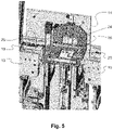
- FIG. 5 shows a perspective view of a portion of a lifting device 14 (or 14 a and 14 b ) of the device, in accordance with a preferred embodiment.
- the lifting device 14 is arranged between a card magazine feeding device 13 arranged upstream thereof and a card magazine output device 15 arranged downstream thereof in such a way that the lifting table 23 of the lifting device 14 is positioned between the two.
- a stacking position 24 is defined on the lifting table 23 , which serves to receive and support an upright card magazine 8 (see FIG. 6 ).
- An extendable stop formation 26 is also provided on the lifting table 23 , which extendable stop formation 26 can in particular be constructed as a stop cylinder.
- FIG. 6 shows a side view of the lifting device 14 .
- the lifting table 23 can be moved perpendicular to its table surface by an appropriate drive 28 , which is constructed as a belt drive or a chain drive, and for this purpose is supported, for example, by rails running along the direction of displacement.
- an appropriate drive 28 which is constructed as a belt drive or a chain drive, and for this purpose is supported, for example, by rails running along the direction of displacement.
- a card magazine 8 can be received, coming from the card magazine feeding device 13 , in an upright position at the stacking position 24 of the lifting table 23 .
- the lifting table 23 is moved upwards in the direction of a centering device 27 (or 27 a , 27 b ), which serves to, and is arranged to, fix the card magazine 8 at its upper end and, at the same time, to provide the centering function which has already been described in the context of FIG. 1 for the transfer of data carriers 5 from the conveying device 4 into the corresponding card magazine 8 .
- a centering device 27 or 27 a , 27 b
- the lifting device 14 also has a drive 10 with a telescopically extendable force transmission element which is arranged underneath the lifting table 23 and which can move into the card magazine through a corresponding gap at the lower end of the card magazine.
- a drive 10 with a telescopically extendable force transmission element which is arranged underneath the lifting table 23 and which can move into the card magazine through a corresponding gap at the lower end of the card magazine.
- it serves to couple to a stack carrier element 8 s of the card magazine 8 and to move the stack carrier element 8 s , and thus a stack of data carriers 5 which may already be stacked on it, along the longitudinal axis of the card magazine 8 in dependence upon its degree of filling (or the number of data carriers 5 already inserted therein).
- This serves in particular to keep the transfer path for the data carriers 5 from the conveying device 4 to the upper end of the stack of data carriers 5 at least substantially constant for successive data carriers 5 .
- FIG. 7 shows a perspective view of a portion of a card magazine output device 15 (or 15 a , 15 b ) of the device 1 , in accordance with a preferred embodiment of the invention. Its structure largely corresponds to that of the card magazine feeding device 13 .
- the portion of the card magazine output device 15 shown in FIG. 7 in particular represents a portion of a buffer area of the card magazine output device 15 , which is defined as the portion which extends between the upstream end of the card magazine feeding device 13 (adjacent to the lifting table 23 ) and a (second) stop member 33 which is shown in FIG. 8 and which is located further downstream.
- the buffer area comprises a (second) driver member 30 , which is constructed similar to the (first) driver member 19 of the card magazine feeding device 13 .
- the (second) driver member 30 serves to move through corresponding gaps in the card magazine output device 15 and the lifting table 23 (see FIG. 5 ) under the card magazine and to engage in a recess or opening on the bottom side of the card magazine 8 and then to pull it by this into the buffer area.
- a (second) transfer member 31 is provided in the buffer area for this purpose, which is or can be coupled to the driver member 30 and is configured to move this and, in particular after its coupling to the card magazine 8 , to pull it in the downstream direction, in order to automatically transfer the card magazine 8 into the buffer area.
- at least one sensor 32 is provided in the buffer area, which, together with further sensors shown in FIG. 8 , forms a (second) sensor unit which serves to detect the position of card magazines 8 at the card magazine output device 15 .
- FIG. 8 shows a perspective view of the downstream portion of the card magazine output device 15 .
- the card magazine output device 15 has an output position 34 with an optional stop bar 35 at which card magazines 8 can be removed whose processing by the device 1 has been completed.
- At least one of the sensors 32 is arranged in such a way that it can be used to detect whether a card magazine 8 is at the output position 34 . If this is the case, the (second) stop member 33 moves into the running groove of the card magazine output device 15 in order to temporarily block the advancement of further card magazines 8 into the output position 34 until this is free again.
- FIG. 9 finally shows a flowchart in order to illustrate a preferred embodiment of the method in accordance with the invention. The method is explained below with reference to the corresponding use of a device 1 —as has been described above with reference to FIGS. 1 to 8 .
- a personalization of a data carrier 5 is carried out in a step S 1 , followed by an inspection of the data carrier 5 .
- the inspection may relate in particular to the mechanical and/or electrical integrity of the data carrier and/or to a check of its personalization carried out beforehand, such as by inscription or printing of data.
- the data carrier 5 is conveyed to the transfer section B of the device 1 as an individual data carrier and in the lying mode of transport by the feeding device 6 .
- a transfer of the data carrier 5 to the conveying device 4 takes place, for onward transport of the data carrier 5 along a conveying path, in the hanging mode of transport.
- the data carrier 5 is brought into contact with the discharge element 7 in a step S 4 , in order to discharge any excess charge which may be present on the data carrier and thereby to discharge the data carrier 5 .
- step S 6 it is selectively released from the conveying device 4 by a mechanical impulse (which is transmitted by blowing driven by compressed air or by an impact of, for example, a pin onto the main face of the data carrier facing towards the conveyor device), centered by the centering device 27 in relation to a receiving opening of a card magazine 8 located at a corresponding stacking position 24 on the lifting table 23 , and transferred into the latter and stacked therein.
- a mechanical impulse which is transmitted by blowing driven by compressed air or by an impact of, for example, a pin onto the main face of the data carrier facing towards the conveyor device
- a distribution scheme is used to automatically decide at which point the selective release of the data carrier 5 from the conveying device 4 is to take place and, accordingly, into which of the card magazines 8 a , 8 b the data carrier 5 is transferred.
- the distribution scheme is defined in such a way that initially all data carriers 5 are stacked in the same card magazine 8 a until the latter is completely filled, after which the transferring and stacking of the subsequent further data carriers 5 into the further card magazine 8 b is carried out until in turn the latter is completely filled, after which, in turn, the stacking into a further card magazine takes place, which in the meantime has moved up to take the place of the first card magazine 8 a.
- step S 7 an alignment process by the corresponding alignment device 9 a , 9 b , as has been described in detail above with reference to FIG. 1 , follows in a further step S 7 , which can either be carried out individually for each of the stacked data carriers 5 , or together for several data carriers 5 .
- the data carriers 5 transferred to a card magazine 8 a , 8 b are counted by a counter.
- step S 8 If, by the stacking of the data carrier 5 , a target counter reading of the counter is reached which corresponds to a complete filling of the card magazine 8 (step S 8 —yes), then in a further step S 9 the card magazine 8 a , 8 b filled with the data carriers 5 is automatically transferred into the card magazine output device 15 a or 15 b and can eventually be removed (ejected) there at the output position 34 of the latter. If this is not the case (S 8 —no), the next data carrier 5 is processed, which, if it has also passed the inspection (S 6 —yes), is then stacked in the same way in the card magazine 8 a or 8 b that is currently to be filled and still has spare capacity.
- step S 5 If, however, a data carrier 5 has not passed the inspection (S 5 —no), the method instead does not move from step S 5 to step S 6 , but to step S 10 , in which the data carrier is selectively released from the conveying device 4 at another location thereof, in particular is blown off in the same way, and is transferred to an elimination area D of the device 1 .
- the data carrier is, in dependence on its corresponding allocation within the classification in step S 11 , either fed again to the personalization and inspection device 3 via the return loop 12 for a further run (S 11 —yes; for example, if only the personalization data were recognized, during the inspection, as incomplete or in other ways inadequate, but the data carrier was otherwise intact), or is finally ejected in a further step S 12 as a faulty data carrier.
- Step S 11 can in particular also be combined with step S 10 in such a way that a separate conveyor belt 11 a is provided for those data carriers 5 or 5 c (see FIG.
- stop cylinder 26 stop formation, in particular stop cylinder
Landscapes
- Engineering & Computer Science (AREA)
- Mechanical Engineering (AREA)
- Physics & Mathematics (AREA)
- General Physics & Mathematics (AREA)
- Theoretical Computer Science (AREA)
- Sheets, Magazines, And Separation Thereof (AREA)
- Feeding Of Articles By Means Other Than Belts Or Rollers (AREA)
Applications Claiming Priority (3)
| Application Number | Priority Date | Filing Date | Title |
|---|---|---|---|
| DE102017111909.4A DE102017111909A1 (de) | 2017-05-31 | 2017-05-31 | Vorrichtung und Verfahren zum Abstapeln von kartenförmigen Datenträgern |
| DE102017111909.4 | 2017-05-31 | ||
| PCT/EP2018/063903 WO2018219852A1 (de) | 2017-05-31 | 2018-05-28 | Vorrichtung und verfahren zum abstapeln von kartenförmigen datenträgern |
Publications (2)
| Publication Number | Publication Date |
|---|---|
| US20210163249A1 US20210163249A1 (en) | 2021-06-03 |
| US11414290B2 true US11414290B2 (en) | 2022-08-16 |
Family
ID=62245330
Family Applications (1)
| Application Number | Title | Priority Date | Filing Date |
|---|---|---|---|
| US16/617,166 Active 2039-04-01 US11414290B2 (en) | 2017-05-31 | 2018-05-28 | Apparatus and method for stacking card-like data carriers |
Country Status (5)
| Country | Link |
|---|---|
| US (1) | US11414290B2 (de) |
| EP (1) | EP3630662B1 (de) |
| CN (1) | CN110891888A (de) |
| DE (1) | DE102017111909A1 (de) |
| WO (1) | WO2018219852A1 (de) |
Families Citing this family (8)
| Publication number | Priority date | Publication date | Assignee | Title |
|---|---|---|---|---|
| CN108231651B (zh) * | 2017-12-26 | 2020-02-21 | 厦门市三安光电科技有限公司 | 微元件转移装置和转移方法 |
| CN112005356A (zh) * | 2018-05-03 | 2020-11-27 | 应用材料公司 | 高速旋转分类器中的基板倾斜控制 |
| TWI809352B (zh) | 2020-02-13 | 2023-07-21 | 瑞士商愛爾康公司 | 用於將眼科鏡片之泡罩條運送到高壓滅菌盒中之方法 |
| DE102021207346A1 (de) * | 2021-07-12 | 2023-01-12 | Körber Technologies Gmbh | Vorrichtung zum Entnehmen oder Abzweigen von Produktsegmenten aus einem Produktstrom der Energiezellen produzierenden Industrie |
| US11945660B2 (en) * | 2021-08-09 | 2024-04-02 | Applied Materials, Inc. | Linear sorter using vacuum belt |
| EP4201495A1 (de) * | 2021-12-27 | 2023-06-28 | Cartamundi Services NV | Vorrichtung zum bereitstellen von kartensätzen |
| EP4201494A1 (de) * | 2021-12-27 | 2023-06-28 | Cartamundi Services NV | Kartenbewegungssystem |
| CN114355170B (zh) * | 2022-01-18 | 2022-11-04 | 深圳市百泰实业股份有限公司 | 一种pcba测试治具自动叠板方法及自动叠板装置 |
Citations (10)
| Publication number | Priority date | Publication date | Assignee | Title |
|---|---|---|---|---|
| DE1923441A1 (de) | 1969-05-08 | 1971-01-21 | Hwm Weh Maschf Hermann | Arbeitsverfahren und Einrichtung zum kontinuierlichen Foerdern,Stapeln und Entstapeln von tafelfoermigem Foerdergut |
| JPS4943971U (de) | 1972-07-20 | 1974-04-17 | ||
| US4236639A (en) * | 1977-07-01 | 1980-12-02 | G.A.O. Gesellschaft Fur Automation Und Organisation Mbh | Method of automatically sorting thin sheet articles |
| EP0095576A2 (de) | 1982-05-27 | 1983-12-07 | Rockwell International Corporation | Apparat zum Beladen eines Behälters für Zeitungen |
| JPS59124650A (ja) | 1982-12-30 | 1984-07-18 | Kawasaki Steel Corp | 板材のバキユ−ム式パイリング装置における多孔ベルト保持装置 |
| GB2183222A (en) | 1985-11-25 | 1987-06-03 | Cubic Western Data | Ticket stacker module |
| US4905843A (en) | 1988-04-07 | 1990-03-06 | U.S. Natural Resources, Inc. | Veneer stacking system |
| DE10202646A1 (de) * | 2002-01-23 | 2003-07-31 | Orga Kartensysteme Gmbh | Transportvorrichtung für Datenträgerkarten |
| DE10202641A1 (de) | 2002-01-23 | 2003-07-31 | Orga Kartensysteme Gmbh | Förder-und Abnahmevorrichtung für Datenträgerkarten |
| US20130062263A1 (en) | 2010-03-26 | 2013-03-14 | Uni-Charm Corporation | Defective-workpiece discharging device |
Family Cites Families (5)
| Publication number | Priority date | Publication date | Assignee | Title |
|---|---|---|---|---|
| DE1282556B (de) * | 1966-12-01 | 1968-11-07 | Ungerer Irma | Fuer verschiedene Blechgroessen geeignete Anlage zum selektiven Foerdern und Stapeln von aufeinanderfolgend zugefuehrten Blechtafeln |
| US3941370A (en) * | 1975-02-24 | 1976-03-02 | Fabricacion De Maquinas | Sheet glass - conveying, classifying and stacking apparatus |
| US4627608A (en) * | 1985-05-01 | 1986-12-09 | Gill Studios, Inc. | Vacuum take-off conveyor |
| EP1061020A1 (de) * | 1999-06-15 | 2000-12-20 | Systraplan Gesellschaft für Planung und Bau von materialflusstechnischen Anlagen mbH u. Co. KG | Grubenlose Einrichtung zum Beschicken und Entsorgen von Bearbeitungsstrassen für flächige Werkstücke |
| US7600751B2 (en) * | 2005-12-01 | 2009-10-13 | Pitney Bowes Inc. | Apparatus for handling mailpieces |
-
2017
- 2017-05-31 DE DE102017111909.4A patent/DE102017111909A1/de active Pending
-
2018
- 2018-05-28 US US16/617,166 patent/US11414290B2/en active Active
- 2018-05-28 CN CN201880036682.8A patent/CN110891888A/zh active Pending
- 2018-05-28 WO PCT/EP2018/063903 patent/WO2018219852A1/de active Application Filing
- 2018-05-28 EP EP18727299.2A patent/EP3630662B1/de active Active
Patent Citations (10)
| Publication number | Priority date | Publication date | Assignee | Title |
|---|---|---|---|---|
| DE1923441A1 (de) | 1969-05-08 | 1971-01-21 | Hwm Weh Maschf Hermann | Arbeitsverfahren und Einrichtung zum kontinuierlichen Foerdern,Stapeln und Entstapeln von tafelfoermigem Foerdergut |
| JPS4943971U (de) | 1972-07-20 | 1974-04-17 | ||
| US4236639A (en) * | 1977-07-01 | 1980-12-02 | G.A.O. Gesellschaft Fur Automation Und Organisation Mbh | Method of automatically sorting thin sheet articles |
| EP0095576A2 (de) | 1982-05-27 | 1983-12-07 | Rockwell International Corporation | Apparat zum Beladen eines Behälters für Zeitungen |
| JPS59124650A (ja) | 1982-12-30 | 1984-07-18 | Kawasaki Steel Corp | 板材のバキユ−ム式パイリング装置における多孔ベルト保持装置 |
| GB2183222A (en) | 1985-11-25 | 1987-06-03 | Cubic Western Data | Ticket stacker module |
| US4905843A (en) | 1988-04-07 | 1990-03-06 | U.S. Natural Resources, Inc. | Veneer stacking system |
| DE10202646A1 (de) * | 2002-01-23 | 2003-07-31 | Orga Kartensysteme Gmbh | Transportvorrichtung für Datenträgerkarten |
| DE10202641A1 (de) | 2002-01-23 | 2003-07-31 | Orga Kartensysteme Gmbh | Förder-und Abnahmevorrichtung für Datenträgerkarten |
| US20130062263A1 (en) | 2010-03-26 | 2013-03-14 | Uni-Charm Corporation | Defective-workpiece discharging device |
Non-Patent Citations (5)
| Title |
|---|
| Chinese Patent Office, 2nd Office Action issued in CN Application No. 201880036682.8, dated May 18, 2021, 12 pages (no English translation available). |
| Chinese Patent Office, Office Action issued in CN Application No. 201880036682.8, dated Sep. 24, 2020, 12 page (art citations provided English-readable on p. 1). |
| German Patent Office, Office Action issued in 10 2017 111 909.4 dated Apr. 14, 2018 (10 pages). |
| Hesse, Stefan, "Grundlagen der Handhabungstechnik" Carl Hanser Verlag GmbH Co KG, 2016, Seiten 142-145, 252-255, 370-376 (17 pages). |
| International Searching Authority, Search Report and Written Opinion issued in PCT/EP2018/063903 dated Sep. 3, 2018 (14 pages). |
Also Published As
| Publication number | Publication date |
|---|---|
| US20210163249A1 (en) | 2021-06-03 |
| EP3630662B1 (de) | 2023-10-04 |
| DE102017111909A1 (de) | 2018-12-06 |
| CN110891888A (zh) | 2020-03-17 |
| EP3630662A1 (de) | 2020-04-08 |
| WO2018219852A1 (de) | 2018-12-06 |
Similar Documents
| Publication | Publication Date | Title |
|---|---|---|
| US11414290B2 (en) | Apparatus and method for stacking card-like data carriers | |
| US5547063A (en) | Apparatus and method of sorting objects | |
| US4468165A (en) | Apparatus for transporting sorted stacked matter | |
| US7397010B2 (en) | Sorting device for flat mail items | |
| US7527261B2 (en) | Mailpiece container for stacking mixed mail and method for stacking mail therein | |
| US7683285B2 (en) | Method of sorting flat mail items | |
| US8983648B2 (en) | Method and device for sorting two types of objects in multiple sorting passes | |
| US20100286815A1 (en) | Method and apparatus for sorting different kinds of articles | |
| US7607649B2 (en) | Apparatuses and methods for staging and processing documents for sheet processing | |
| US20040153208A1 (en) | Method for sorting flat mail items in delivery sequence order | |
| US20090060698A1 (en) | Pile Transfer Device and Method | |
| CN110899126A (zh) | 用于对物体分类的分类设施及方法 | |
| US11311913B2 (en) | Installation for sorting articles such as parcels or packets with a system for monitoring the positioning of the articles by outline detection | |
| US20130248324A1 (en) | Transport device and transport method which rotate a plurality of transported holding devices | |
| KR101908765B1 (ko) | 카드 자동 포장 시스템 | |
| US20120097584A1 (en) | Route enhanced dispatch module | |
| CN113369175B (zh) | 一种用于电感器的自动测包系统及测包方法 | |
| US10008066B2 (en) | Method and apparatus for handling value documents | |
| CN112640075A (zh) | 元件分类装置 | |
| US11158135B2 (en) | Dispensing apparatus for dispensing card-shaped data carriers | |
| CA3042269C (en) | Dispensing apparatus for dispensing card-shaped data carriers | |
| US6915909B2 (en) | Device for receiving multi-format envelopes | |
| KR20040100071A (ko) | 카드 분류장치 및 그 제어방법 | |
| WO2009139728A1 (en) | Method and apparatus for integrated circuit inspection | |
| KR101281526B1 (ko) | 우편물 분류를 위한 스태커 모듈 |
Legal Events
| Date | Code | Title | Description |
|---|---|---|---|
| FEPP | Fee payment procedure |
Free format text: ENTITY STATUS SET TO UNDISCOUNTED (ORIGINAL EVENT CODE: BIG.); ENTITY STATUS OF PATENT OWNER: LARGE ENTITY |
|
| AS | Assignment |
Owner name: MUHLBAUER GMBH & CO. KG, GERMANY Free format text: ASSIGNMENT OF ASSIGNORS INTEREST;ASSIGNORS:KRAPF, BENJAMIN;STREHLE, MARKUS;SIGNING DATES FROM 20191219 TO 20200326;REEL/FRAME:052293/0568 |
|
| STPP | Information on status: patent application and granting procedure in general |
Free format text: DOCKETED NEW CASE - READY FOR EXAMINATION |
|
| STPP | Information on status: patent application and granting procedure in general |
Free format text: NON FINAL ACTION MAILED |
|
| STPP | Information on status: patent application and granting procedure in general |
Free format text: FINAL REJECTION MAILED |
|
| STPP | Information on status: patent application and granting procedure in general |
Free format text: RESPONSE AFTER FINAL ACTION FORWARDED TO EXAMINER |
|
| STPP | Information on status: patent application and granting procedure in general |
Free format text: NOTICE OF ALLOWANCE MAILED -- APPLICATION RECEIVED IN OFFICE OF PUBLICATIONS |
|
| STPP | Information on status: patent application and granting procedure in general |
Free format text: PUBLICATIONS -- ISSUE FEE PAYMENT VERIFIED |
|
| STCF | Information on status: patent grant |
Free format text: PATENTED CASE |
|
| AS | Assignment |
Owner name: MB AUTOMATION GMBH & CO. KG, GERMANY Free format text: CHANGE OF NAME;ASSIGNOR:MUHLBAUER GMBH & CO. KG;REEL/FRAME:065193/0114 Effective date: 20230523 |